TRACK TRAIN DYNAMICS
Track Train Dynamics
• VEHICLE DYNAMICS
– LATERAL STABILITY
– VERTICAL STABILITY
– CURVING BEHAVIOUR
• TRAIN DYNAMICS
– LONGITUDINAL TRAIN DYNAMICS
– COLLISION BEHAVIOUR
– YARD IMPACTS
Track Train Dynamics
• Field Trials – Expensive and time consuming
• With fast digital computers available, studies
now done using computer simulation models
• Some simulation programs –
– NUCARS
– ADAMS
– AGEM
– MEDYNA
Track Train Dynamics
• VERTICAL DYNAMICS
Wheel follows the vertical rail profile – hence
behaviour in vertical mode can be simulated and
predicted
• LATERAL DYNAMICS
Wheel is not bound to follow the lateral rail
profile – hence behaviour is rather random in
nature and cannot be easily predicted
Track Train Dynamics
LATERAL DYNAMICS
Hunting – refers to oscillations of a vehicle in
lateral mode
Tread Taper – causes sustained lateral oscillations
– Axle/bogie may translate laterally
– Axle may rotate about vertical axis passing through
centre of axle
– Bogie may rotate about vertical axis through centre
pivot
Track Train Dynamics
Hunting
– In extreme case, may cause flutter
– Some restraint provided by couplers
– Maximum oscillations on free end of last vehicle
(Hence during oscillation trials, the free end of last
vehicle is normally instrumented)
– Centre Pivot and side bearers provide damping to
rotation
Track Train Dynamics
VERTICAL DYNAMICS
Undamped System
• Free Vibrations
• Forced Vibrations
Damped System
• Free Vibrations
• Forced Vibrations

Track Train Dynamics
Vertical Dynamics Undamped System – Free Vibrations
Track Train Dynamics
Vertical Dynamics Undamped System – Free Vibrations
The Solution :
y = -h cos ωt displacement of mass m
a = h(k/m) cos ωt acceleration of mass m
f = ω/2π frequency of mass m
This is SIMPLE HARMONIC MOTION
Max. Accln of ‘m’ depends on k/m. Hence for this effect to
be less, ‘k’ should be small i.e. spring should be soft

Track Train Dynamics
Vertical Dynamics Undamped System – Forced Vibrations
Forcing frequency :
tyy tsinmax
Track Train Dynamics
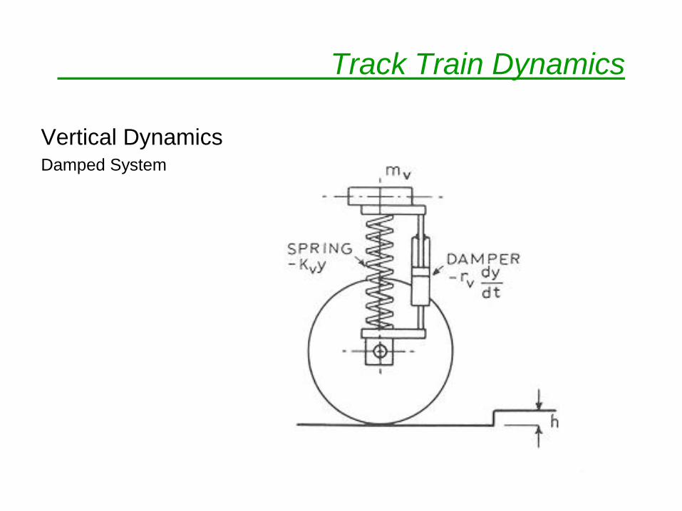
Vertical Dynamics Damped System
Track Train Dynamics
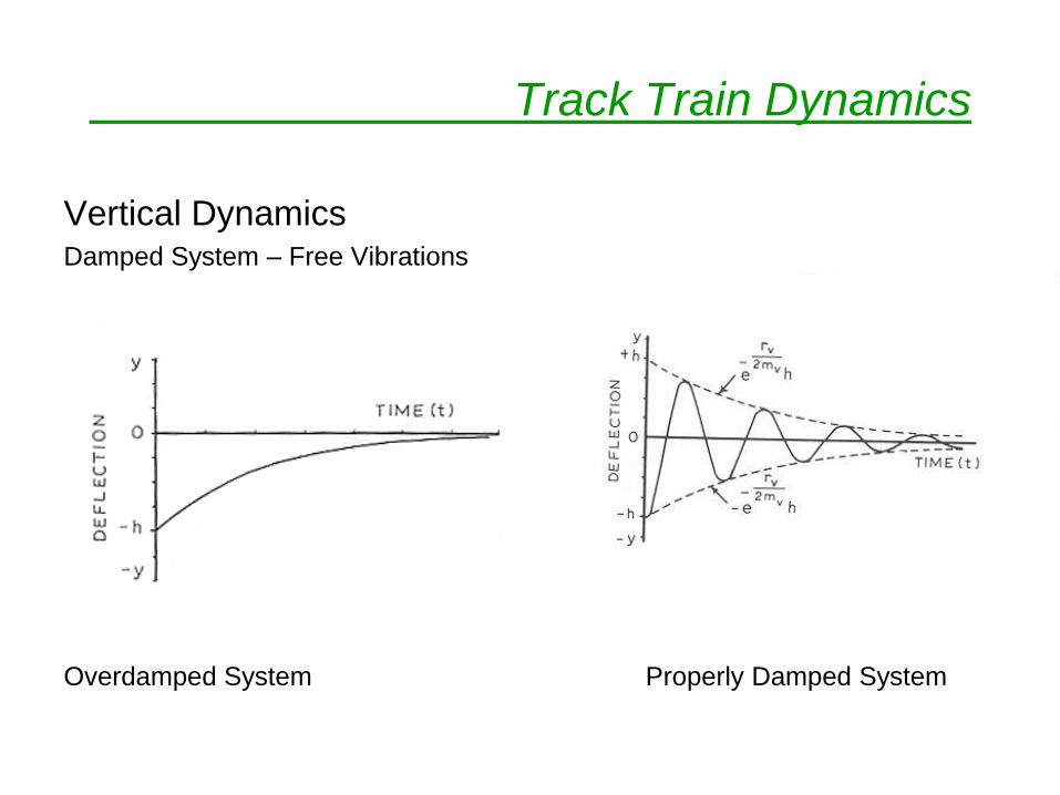
Vertical Dynamics Damped System – Free Vibrations
Overdamped System Properly Damped System
Track Train Dynamics
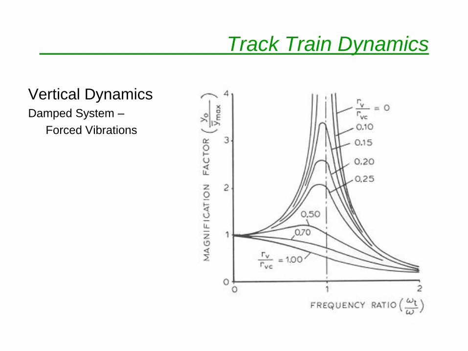
Vertical Dynamics Damped System –
Forced Vibrations
Track Train Dynamics
LONGITUDINAL TRAIN DYNAMICS
– Study of development of longitudinal coupler forces
– Longitudinal forces develop from operation of
vehicles coupled by spring assemblage (draft gear,
cushioning device etc.)
Problems due to longitudinal forces –
– Coupler breakage
– Bunching

Track Train Dynamics
Factors affecting longitudinal forces –
• Physical
– Available tractive effort
– Weight of locomotive(s) and other stock
– Grades, curves in section
– Characteristics of Braking System
– Type of draft gears and cushioning units
Track Train Dynamics
Factors affecting longitudinal forces –
• Operational
– Train make-up - No. of locomotives, cars and their
positions
– Train Handling - Types of throttle and brake
manipulations used by drivers
Track Train Dynamics
Train Make-Up
• Deals with positioning of locomotives and
cars in the train
• Weakest draftgear component – knuckle :
intentionally so designed for ease of
replacement

Track Train Dynamics
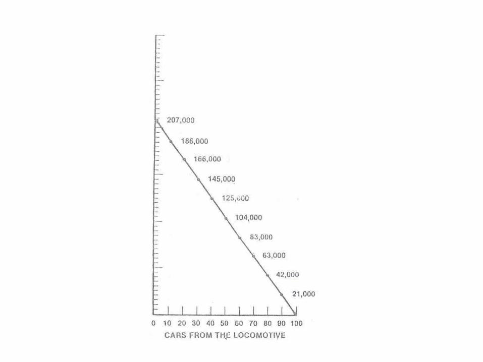
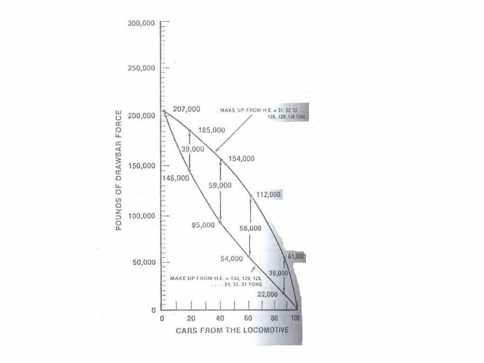
Draw Bar Forces
• Max in the 1st car
• Decrease in magnitude upto last car
• Under steady state, DB forces decrease
uniformly for equally loaded cars
Track Train Dynamics
Draw Bar Forces
• Cars not loaded uniformly – how should they be
positioned ?
• In general – heaviest car in the front followed by
successively lighter cars towards the end
Track Train Dynamics
Reasons for heavy cars in the front –
(From DB Forces point of view)
• Except for the first car, drawbar forces will be
lower
• Highest drawbar forces transmitted through
fewer cars – thus lessening the probability of
train separation
Track Train Dynamics
Reasons for heavy cars in the front – (From Dynamic Stability Point of View)
• Under full brake power, front portion will decelerate at a lower rate compared to rear, keeping the train a little stretched – a desirable condition
• Due to brake application time lag, front cars start braking early but their higher weight somewhat compensates for difference in deceleration rate from rear, reducing effects of bunching
• Due to lighter cars at rear, bunching will be with lesser force

Track Train Dynamics
There is nothing inherently unsafe in
handling trains with mixed distribution of
heavy & light cars or with heavier loads at
the rear, so long as proper train handling
procedures are followed and draw bar
forces are within limits.
How to determine draw bar forces ?
Track Train Dynamics
Methods of determining draw bar forces - Field Trials :
Couplers are removed from vehicles, strain gauged, calibrated and re-fitted
Limitations –
• Only a few couplers can be instrumented
• Expensive
• Very time consuming
• Generally only the lead coupler is instrumented - this is also used to verify tractive effort of locomotive

Track Train Dynamics
Computer Simulation Models
Generally two types of models:
a. Complete data is fed into the computer
including braking data – computer
outputs coupler forces for the particular
set of data
Track Train Dynamics
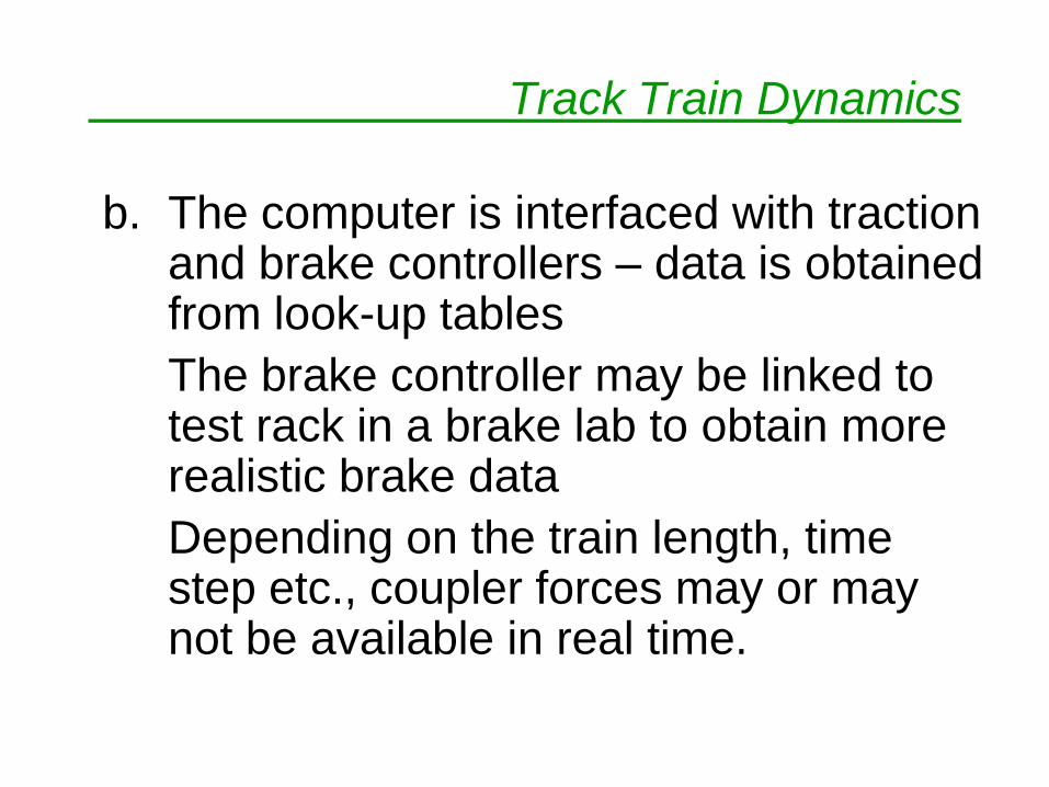
b. The computer is interfaced with traction and brake controllers – data is obtained from look-up tables
The brake controller may be linked to test rack in a brake lab to obtain more realistic brake data
Depending on the train length, time step etc., coupler forces may or may not be available in real time.

Track Train Dynamics
Advanced Version : Loco Simulator
In IR, computer software for calculation of
coupler forces not available.
Software available only for vehicle dynamics
– ADAMS
Track Train Dynamics
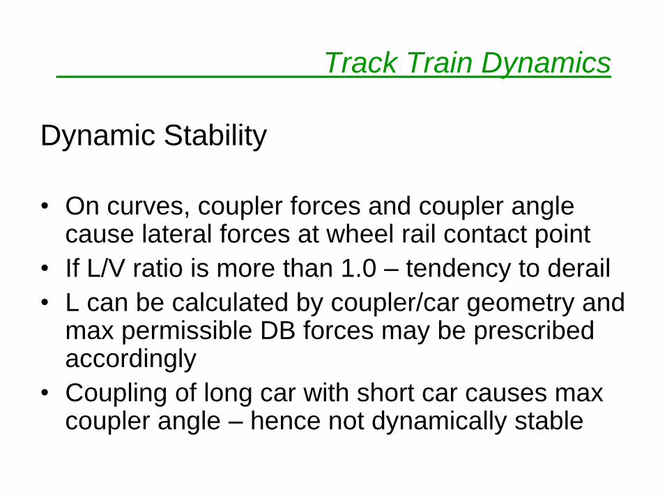
Dynamic Stability
• On curves, coupler forces and coupler angle cause lateral forces at wheel rail contact point
• If L/V ratio is more than 1.0 – tendency to derail
• L can be calculated by coupler/car geometry and max permissible DB forces may be prescribed accordingly
• Coupling of long car with short car causes max coupler angle – hence not dynamically stable
Track Train Dynamics
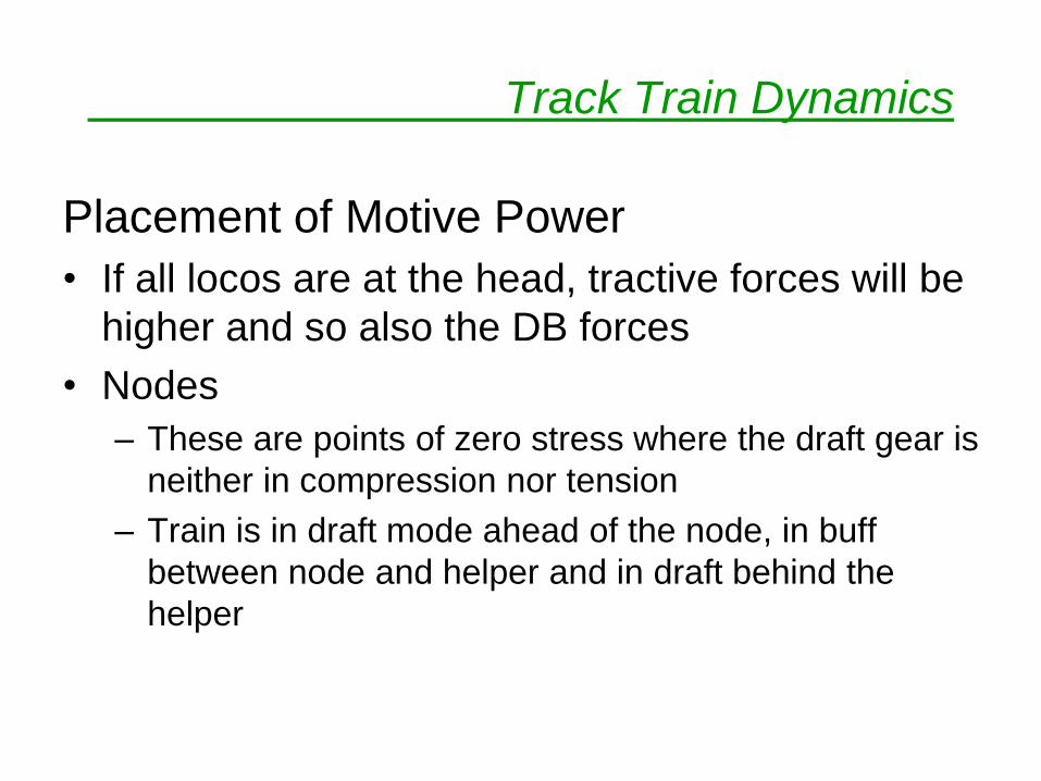
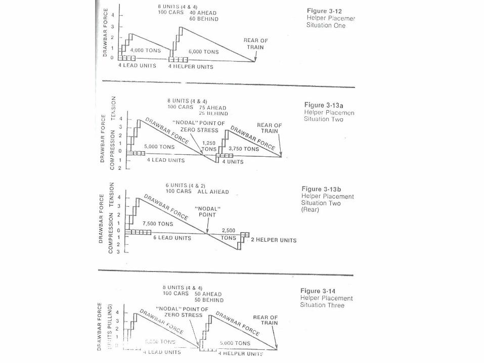
Placement of Motive Power
• If all locos are at the head, tractive forces will be
higher and so also the DB forces
• Nodes
– These are points of zero stress where the draft gear is
neither in compression nor tension
– Train is in draft mode ahead of the node, in buff
between node and helper and in draft behind the
helper
Track Train Dynamics
Operational Considerations
– In a fully graded section, locomotives may be
suitably placed at the time of train formation
itself.
– In a section with part grade, helper can be
attached only at the rear or front
Track Train Dynamics
There are no hard and fast rules about
positioning of locomotives in a train except that :
– The draft and buff forces should be within prescribed
limits
– The DB forces may also be limited by the max
curvatures in the section
In general, optimum location of loco may be
determined for the particular territory of
operation by using computer simulation models
Track Train Dynamics
Train Handling : Some Considerations
– At start, loco brakes may be used to restrict
the train speed upto about 1.5 km/h until the
entire train has started moving – particularly
important if heavier loads are at the rear
– All changes (notching up or braking) should
be made slowly to prevent shuttling due to
slack
Track Train Dynamics
Train handling – Slowing & Stopping
Two Methods :
– Slack Stretched Method
Minimum train brakes should be applied while working power – throttle should be reduced after brakes become effective throughout the train
– Slack Bunched Method
By the use of dynamic brakes and train brakes
Track Train Dynamics
Train handling – Slowing & Stopping
– If heavier loads are at the rear, slack stretched
method may cause problems at low speeds – heavier
cars may run-into lighter cars – in such cases, slack
bunched method may be used with care
– The optimum manipulations of throttle, dynamic
brakes, loco brakes and train brakes may be
determined for a particular type of territory by using
simulation models and drivers may be trained
accordingly

Thank You !


