
Describes how to handle the product.
Describes setup and installation of the product and peripherals.
Describes how to control the printer and necessary information when you develop applications.
Describes general specifications and character code tables.
Describes features for the product.
Technical Reference GuideSeriesSeries /
M00079105
Rev. F
Product Overview
Setup
Handling
Application Development Information
Appendix
2
Cautions• No part of this document may be reproduced, stored in a retrieval system, or transmitted in any form or
by any means, electronic, mechanical, photocopying, recording, or otherwise, without the prior written
permission of Seiko Epson Corporation.
• The contents of this document are subject to change without notice. Please contact us for the latest
information.
• While every precaution has been taken in the preparation of this document, Seiko Epson Corporation
assumes no responsibility for errors or omissions.
• Neither is any liability assumed for damages resulting from the use of the information contained herein.
• Neither Seiko Epson Corporation nor its affiliates shall be liable to the purchaser of this product or third
parties for damages, losses, costs, or expenses incurred by the purchaser or third parties as a result of:
accident, misuse, or abuse of this product or unauthorized modifications, repairs, or alterations to this
product, or (excluding the U.S.) failure to strictly comply with Seiko Epson Corporation’s operating and
maintenance instructions.
• Seiko Epson Corporation shall not be liable against any damages or problems arising from the use of any
options or any consumable products other than those designated as Original EPSON Products or EPSON
Approved Products by Seiko Epson Corporation.
TrademarksEPSON is a registered trademark of Seiko Epson Corporation.
Exceed Your Vision and ESC/Label are registered trademarks or trademarks of Seiko Epson Corporation.
Microsoft®, Windows®, Windows Vista®, and Windows Server® are either registered trademarks or trade-
marks of Microsoft Corporation in the United States and other countries.
Zebra Technologies Corporation and ZPL II are the registered trademarks or trademarks of Zebra Technolo-
gies Corporation.
Intel®, Celeron®, and Pentium® are trademarks of Intel Corporation in the U.S. and/or other countries.
AMD® and AMD AthlonTM are a trademark or registered trademark of Advanced Micro Devices, Inc.
BarTender® is registered trademark of Seagull Scientific, Inc. in the United States and other countries.
Seagull Scientific is trademark of Seagull Scientific, Inc. in the United States and other countries.
NiceLabel® is trademarks or registered trademarks of Euro Plus d.o.o.
CODESOFT is registered trademarks or trademarks of TEKLYNX International.
All other trademarks are the property of their respective owners and used for identification purpose only.
© Seiko Epson Corporation 2014-2015. All rights reserved.

3
For SafetyThis document explains the functions of and how to operate this product and the software, the setup from installation until printing, information regarding maintenance, and solutions to various kinds of trouble. Be sure to read this document thoroughly before use and to use this product properly.
You can easily setup this product using Install Navi.
Key to Symbols
The symbols in this manual are identified by their level of importance, as defined below. Read the following carefully before handling the product.
Cautions on Installation
WARNING
Handling the product improperly by ignoring this symbol can lead to death or seri-
ous injury.
CAUTION
Handling the product improperly by ignoring this symbol can lead to injury and property
damage.
Indicates supplementary notes and other useful information.
WARNING
Do not block the air vents of this product. Doing so can result in heat accumulated
in the product causing a fire. ("Rear Side" on page 21)
Do not cover the product with a cloth or install it in a poorly-ventilated location.
Make sure to allow installation space as specified in this manual. ("Location
Appropriate for Installation" on page 39)
CAUTION
Do not install/store the product in an unstable location or in a location subject to vibration
from other devices. Equipment may fall or collapse, causing breakage and possible
injury.
Do not install the product in a location exposed to oily smoke or dust, or in a humid
location. Doing so may cause electric shock or fire.
Use a natural posture when lifting this product. Lifting the product in an inappropriate
posture may cause injury.
Do not carry this product alone. Two or more people are required while unpacking or
moving the product. The weight of this product is approximately 37 kg {81.57 lb}.
("Installing the Printer" on page 38)
Hold the parts of the product specified in this manual when lifting up this product.
Otherwise, the product may fall or your finger may be caught when you lower the
product, resulting in injury. ("Installing the Printer" on page 38)
While installing the printer, make sure that no cords or foreign objects are tucked under
the printer.
4
Cautions on Power Supply
WARNING
Do not allow dust or foreign materials to adhere to the power plug. Accumulated
dust or foreign material may cause electric shock or fire.
Insert the power plug securely into the socket. Failure to insert the plug securely
may cause electric shock or fire.
Use only the power cable supplied with this product. In addition, use the supplied
power cable only for this product. Other use may cause electric shock or fire.
Do not use a damaged power cable. Doing so may cause electric shock or fire.Contact a Seiko Epson service center for advice if the power cable is damaged.
Observe the following points so as not to damage the power cable:
Do not modify the power cable.
Do not place heavy objects on the power cable.
Do not forcibly bend, twist or pull the power cable.
Do not locate the power plug near a heating device.
Do not hold the power plug with a wet hand. Doing so may cause electric shock.
Do not connect too many power cables to one outlet. Doing so may cause fire.
Disconnect the power plug from the outlet on a periodical basis, and clean the
areas around and between the blades. Leaving the power plug connected to the
outlet for a long period of time may cause dust to accumulate on the blade root,
resulting in a short-circuit or fire.
Hold the plug and do not pull the cable when disconnecting the power plug from
the outlet. Pulling the cable may damage the cable or deform the plug, causing
electric shock or fire.
CAUTION
To ensure safety, unplug this product before leaving it unused for an extended period.

5
Cautions on Handling
WARNING
Do not use this product in a location with volatile substances such as alcohol or
paint thinner, or near fire. Doing so may cause electric shock or fire.
Shut down the product immediately if it produces smoke, a strange odor, or
unusual noise. Continued use may cause electric shock or fire. Immediately
unplug the product when a fault or other problem occurs, and contact your dealer
or a Seiko Epson service center for advice.
Shut down the product immediately if water or other liquid spills into this product.
Continued use may cause electric shock or fire. Immediately unplug the product
and contact your dealer or a Seiko Epson service center for advice.
Never disassemble or repair this product. Tampering with this product may result
in injury or fire.
Do not use this product in an environment where inflammable gas or explosive
gas may exist. Do not use aerosol sprayers containing flammable gas inside or
around this product. Doing so may cause fire.
Do not connect cables in ways other than those mentioned in this manual. Doing
so may cause fire. It may also damage other devices.
Do not touch the areas inside the product other than those mentioned in this
manual. Doing so may cause electric shock or burns.
Do not insert metal or flammable materials, or allow them to fall into the product.
Doing so may cause electric shock or fire.
Use a power cable that has acquired a safety standard certification and has a
power supply system (PE) terminal. Make sure you earth the terminal; otherwise it
may cause electric shock.
CAUTION
Do not allow anyone to stand or place heavy objects on top of this product. Equipment
may fall or collapse, causing breakage and possible injury.
Install the cables and optional products in the proper direction according to the proper
procedures. Failure to install correctly may cause fire or injury. Follow the instructions in
this manual to install them properly.
Before moving the product, shut down and unplug the product, and make sure that all
the cables are disconnected. Failure to do so may damage a cable, causing electric
shock or fire.
Do not store or transport the product in a tilted, standing or upside-down position. Doing
so may cause the ink to leak.
Using in the presence of silicon gas (silicon adhesive, silicon oil, silicon powder, etc.)
including siloxane and of malignant gas (nitric acid, hydrosulfuric, ammonia, chlorine,
etc.) may cause contact failure at contact points in a mechanical switch and a DC motor
etc. in a short time because of adhesion or oxidization of the insulation film.
If the printer is out of use for a prolonged period, it could develop problems due to dust
building up on the external supply paper or entering through it, etc. Therefore, protect
the printer with a cover or similar, or remove the paper and store it in a dust-free place.
Do not allow a solvent that is based on benzene, thinner, toluene, or ketones to adhere
to the printer surface as they may deteriorate or damage plastic.
6
Cautions on the Ink Cartridge / Maintenance box
CAUTION
Do not touch IC chips on the ink cartridges or Maintenance box. Doing so may cause
operating/printing malfunction.
This product uses ink cartridges equipped with an IC chip that monitors the amount of
ink used by each cartridge. Cartridges are usable even if they are removed and
reinstalled. However, if an ink cartridge in which little amount of ink remains is removed
and reinstalled, it may not be usable. Some ink is consumed each time cartridges are
installed because the product automatically checks their reliability.
Install all ink cartridges. Printing is not possible even if only one ink cartridge is missing.
Since ink cartridges are designed to stop the operation before ink runs out completely to
maintain the quality of the print head, some ink remains in the used ink cartridge.
All the ink colors are consumed also for the maintenance operations when an ink
cartridge is replaced and for print head cleaning.
Flashing (Power) LED indicates that head cleaning, ink charging, or printing is in
progress. Do not open or close the Roll paper cover, Ink cartridge cover, or Maintenance
box cover, or turn off the power.
Do not turn off the product or open the ink cartridge cover while charging ink ( (Power)
LED is flashing). Opening the cover may cause the ink to be recharged, resulting in more
ink being consumed. Also, it may cause printing malfunction.
Even for monochrome printing (printing of monochrome image), all the ink colors are
used in an operation designed to maintain the printing and print head quality.
Do not disassemble the ink cartridges or Maintenance box, or supply or replace ink. If
you disassemble them, ink may get into your eyes or adhere to your skin. It may also
prevent you from printing correctly. Ink may leak and damage the printer.
Do not remodel the ink cartridge. Doing so may cause printing malfunction.
Use of an old ink cartridge may result in reduced print quality. Use it up within six months
after opening the package. The usage period for ink cartridges is printed on the
packaging of individual ink cartridges.
Do not reuse a maintenance box which has removed and detached a long period.
Store the ink cartridges or Maintenance box out of the reach of children. Do not drink ink.
If ink contacts your skin, eyes, or mouth, take the following actions.
When it gets onto your skin, immediately wash the area with soap and water.
When ink gets into your eyes, immediately flush them with water. Leaving the ink as is
may result in bloodshot eyes or mild inflammation. If something is wrong, immediately
consult with a doctor.
When ink gets into your mouth, immediately spit it and consult with a doctor.
Be careful when handling the ink cartridges or Maintenance box as if ink leaks and
adheres to clothes, it may not come off even after washing it.
There may be some ink around the ink supply port on the removed ink cartridge. Take
care so that it does not stain the desk or other surface.
Do not remove the ink cartridge or maintenance box, except when you replace it.
Do not open the ink cartridge package until you are ready to install it in the product.
Do not shake the ink cartridges or Maintenance box strongly. If you shake or swing them
strongly, or push the sides strongly, ink may leak from the cartridges or Maintenance
box.
Do not push the supply port of the ink cartridges or Maintenance box as ink may leak.
7
CAUTION
Do not allow foreign objects to fall into the cartridge installation section. Doing so may
cause printing malfunction. Remove any object that might have fallen into the installation
section, taking care not to damage the section.
Inside the ink cartridge holder that is in the printer where ink cartridges are stored has a
needle for supplying ink to the printer. Do not insert your fingers and so on as it may
stain.
When ink is charged for the first time (right after purchase), ink is consumed for filling the
print head nozzle (ink discharge holes) to get ready for printing. That is why the number
of the printable sheets may be fewer than for the cartridges to be installed later.
When using the printer for the first time, the replacement interval for the maintenance
box is shorter than usual as ink charging consumes the ink.
If you turn the power off the product using the power button, the print head is
automatically capped, which prevents the ink from drying. After installing the ink
cartridges, be sure to turn the power off using the power button when you are not using
the product. Do not pull out the power plug or trip the breaker while the power is on.
Printing on water-repellent paper such as art paper, which is slow-drying, may cause
print stains. Also, printing on glossy paper may cause finger prints on the paper or ink
may adhere to your fingers when you touch it. Select paper not to case print stains
before use.
If you transport the printer without ink cartridges installed, ink may leak. Make sure the
Ink cartridges are installed when transporting the printer.
If you use a non-genuine Maintenance box that does not support this printer, it may
affect the printer or deteriorate the print quality and cause a non-returnable error,
preventing the printer's optimum performance. We recommend using a genuine
Maintenance box.
Do not allow a solvent that is based on benzene, thinner, toluene, or ketones to adhere
to the ink cartridges or Maintenance box as it may deteriorate or damage plastic.
When disposing of the ink cartridges or Maintenance box, follow the laws, legislations,
and regulations of your country or community.
8
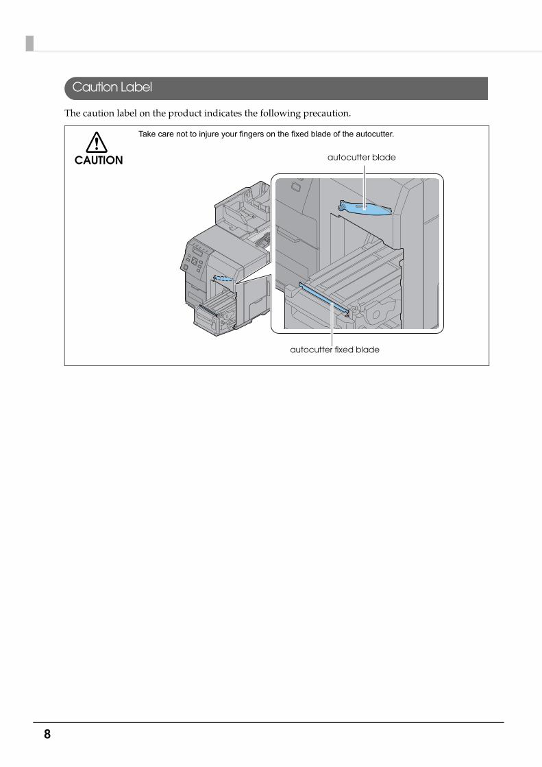
Caution Label
The caution label on the product indicates the following precaution.
CAUTION
Take care not to injure your fingers on the fixed blade of the autocutter.
autocutter blade
autocutter fixed blade

9
Restriction of UseWhen this product is used for applications requiring high reliability/safety, such as transportation devices related to aviation, rail, marine, automotive, etc.; disaster prevention devices; various safety devices, etc.; or functional/precision devices, etc., you should use this product only after giving consideration to including fail-safes and redundancies into your design to maintain safety and total system reliability. Because this product was not intended for use in applications requiring extremely high reliability/safety, such as aerospace equipment, main communication equipment, nuclear power control equipment, or medical equipment related to direct medical care, etc., please make your own judgment on this product's suitability after a full evaluation.
About this Manual
Aim of the Manual
This manual was created to provide information on development, design, and installation of systems and development and design of printer applications for developers.
Manual Content
The manual is made up of the following sections:
Chapter 1 Product Overview
Chapter 2 Setup
Chapter 3 Handling
Chapter 4 Application Development Information
Appendix Product Specifications

10
Contents■ For Safety .............................................................................................................................. 3
Key to Symbols ........................................................................................................................................3Cautions on Installation .........................................................................................................................3Cautions on Power Supply.....................................................................................................................4Cautions on Handling ............................................................................................................................5Cautions on the Ink Cartridge / Maintenance box ...........................................................................6Caution Label .........................................................................................................................................8
■ Restriction of Use .................................................................................................................. 9
■ About this Manual ................................................................................................................ 9
Aim of the Manual .................................................................................................................................9Manual Content .....................................................................................................................................9
■ Contents.............................................................................................................................. 10
Product Overview........................................................................15
■ Features............................................................................................................................... 15
Printing ...................................................................................................................................................15Operability.............................................................................................................................................16Reliability................................................................................................................................................16Easy setup..............................................................................................................................................16How to Print ...........................................................................................................................................16Other Features ......................................................................................................................................17
■ Part Names and Functions ................................................................................................ 18
Front Side ...............................................................................................................................................18Operation Panel ...................................................................................................................................19Rear Side ...............................................................................................................................................21
■ Nozzle Verification Technology ........................................................................................ 22
Setting the Nozzle Verification Technology .......................................................................................22Dot substitution .....................................................................................................................................24
■ Periodic auto cleaning ...................................................................................................... 25
■ Status/Error Indications ...................................................................................................... 26
Ink Cartridge and Maintenance Box Status......................................................................................31Beeper ...................................................................................................................................................32

11
Setup.............................................................................................33
■ Install Navi .......................................................................................................................... 34
■ Work flow to set up this product without using the Install Navi ...................................... 36
■ Checking the Items Included in the Package ................................................................ 37
■ Installing the Printer............................................................................................................ 38
Location Appropriate for Installation .................................................................................................39
■ Connecting the Power Cable ........................................................................................... 40
■ Connecting the Interface Cable ...................................................................................... 41
■ Turning On/Off .................................................................................................................... 42
Turning On .............................................................................................................................................42Turning Off .............................................................................................................................................42
■ Installing the Ink Cartridge................................................................................................ 43
■ Installing the Maintenance box........................................................................................ 47
■ REWINDER............................................................................................................................ 50
How to install the REWINDER ...............................................................................................................50Removing the rewinder .......................................................................................................................51Attaching the paper leading edge to the rewinder .......................................................................52
■ Setting the Paper................................................................................................................ 54
Setting the Roll Paper...........................................................................................................................54Setting the Fanfold Paper....................................................................................................................62How to eject paper for paper replacement ....................................................................................63Ejection Angle of Printed Paper .........................................................................................................64
■ Printer settings..................................................................................................................... 65
Language Setting.................................................................................................................................65Time Setting...........................................................................................................................................66Network settings ...................................................................................................................................67
■ Paper settings ..................................................................................................................... 69
Set using a printer driver ......................................................................................................................69Setting using the PrinterSetting ...........................................................................................................72Setting with the operation panel........................................................................................................75
■ Test printing......................................................................................................................... 76
Test Printing............................................................................................................................................77
■ How to Display the Printer Driver....................................................................................... 78
12
Handling .......................................................................................79
■ List of printer setting items ................................................................................................. 79
■ Setting panel switch........................................................................................................... 82
Printing the status sheet (Network settings).......................................................................................86Favorite ..................................................................................................................................................87
■ PrinterSetting....................................................................................................................... 89
Starting the PrinterSetting ....................................................................................................................90Apply settings........................................................................................................................................92Media settings.......................................................................................................................................93Layout settings ......................................................................................................................................94Position adjustment ..............................................................................................................................96Print results adjustment ........................................................................................................................98Store data in the printer.......................................................................................................................99Background image settings ..............................................................................................................100Print head maintenance ...................................................................................................................102Printer settings .....................................................................................................................................103Panel settings ......................................................................................................................................104Nozzle check settings.........................................................................................................................105Advanced settings .............................................................................................................................106Initialize printer ....................................................................................................................................110Printer information ..............................................................................................................................111Settings save and restore ..................................................................................................................113Option..................................................................................................................................................114
■ Setting the Printer Driver .................................................................................................. 115
Favorite Setting ...................................................................................................................................115User Defined Information ...................................................................................................................118Exporting/ Importing Printer Driver Settings .....................................................................................118Barcode Printing .................................................................................................................................1212D symbol Printing ..............................................................................................................................131Barcode and 2D Symbol Font Printing on .NET Environment.........................................................138Banding Reduction ............................................................................................................................140Start the PrinterSetting from the printer driver. ................................................................................141Setting EPSON Status Monitor 3.........................................................................................................142Restricted items of printer drivers......................................................................................................148
■ USB Printer Class Device Replacement Service............................................................ 149
Uninstallation of USB Printer Class Device Replacement Service .................................................149Restrictions in USB Printer Class Device Replacement Service .....................................................150
■ Reprint ............................................................................................................................... 151
■ Setting the Dip Switches .................................................................................................. 152
Setting Procedure...............................................................................................................................152
■ Cleaning ........................................................................................................................... 153
Cleaning the autocutter ...................................................................................................................153
13
■ How to Clean the Case ................................................................................................... 153
■ Long-term Storage of the Product After Ink Charging ................................................. 154
Storing the product............................................................................................................................ 154Restart the printer after long-term storage..................................................................................... 155
■ Precautions when transporting ....................................................................................... 156
■ Troubleshooting ................................................................................................................ 157
Error Processing .................................................................................................................................. 157Warning Processing............................................................................................................................ 162Printer Driver........................................................................................................................................ 163Poor print quality ................................................................................................................................ 164Unclean media .................................................................................................................................. 167Printable area .................................................................................................................................... 167Detection failure ................................................................................................................................ 168External supply ................................................................................................................................... 168Paper is jammed................................................................................................................................ 169
Application Development Information....................................173
■ How to Control the Printer................................................................................................ 173
Using label printing application ....................................................................................................... 173Using the Epson Inkjet Label Printer SDK.......................................................................................... 174Using the ESC/Label commands...................................................................................................... 174Changing Printer Settings and Replacing the Printer.................................................................... 175
■ Software and Manuals ..................................................................................................... 180
■ Installing software ............................................................................................................ 182
Software installation procedures...................................................................................................... 182
14
Appendix....................................................................................185
■ Product Specifications..................................................................................................... 185
Operating Environment .....................................................................................................................187Printing Specifications ........................................................................................................................188Paper Specifications ..........................................................................................................................189Paper detection method ..................................................................................................................196Print Area and Cutting Position.........................................................................................................197Electrical Characteristics ...................................................................................................................205Reliability..............................................................................................................................................206Environmental Conditions..................................................................................................................207External Dimensions............................................................................................................................208
■ Consumable Product Specifications.............................................................................. 211
Ink Cartridge .......................................................................................................................................211Maintenance Box...............................................................................................................................211
■ Option Specifications ...................................................................................................... 212
Rewinder (TU-RC7508)........................................................................................................................212
■ LCD Display Specifications for the Number of Printed Copies..................................... 213
Display While Printing .........................................................................................................................213Error Display While Printing.................................................................................................................213Display When the Number of Printed Copies is Carried Up to 8 digits.........................................213
■ Downloading Drivers, Utilities, and Manuals ................................................................. 214
■ Media detector and paper path settings when using label printing applications215
Changing the media detector settings in BarTender ....................................................................216Changing the paper path settings in BarTender ............................................................................218Changing the media detector settings in NiceLabel ....................................................................219Changing the paper path settings in NiceLabel............................................................................221Changing the media detector settings in CODESOFT ...................................................................222Changing the paper path settings in CODESOFT ..........................................................................223
■ For Inquiries....................................................................................................................... 224
15
Chapter 1 Product Overview
1
Product OverviewThis chapter describes features of the product.
FeaturesTM-C7500/TM-C7500G is a 4-color inkjet label printer that offers high processing speed, operability and reliability required for on-demand label printing.
Printing
High speed printing• Actualizes 300 mm/s high speed printing. (600 dpi x 1200 dpi line inkjet printing)
• A large capacity ink tank was adopted to reduce time lost from ink replacement.
• Able to rewind roll paper after printing with the optional rewinder (Model No.: TU-RP7508).
Color Printing• 4-color ink printing (Black, Cyan, Magenta, Yellow)
• Resolution 600 dpi x 1200 dpidpi: dots per 25.4 mm (dots per inch)
Supporting diverse media types• Supports 8-inch diameter roll paper and fanfold paper
• Supports full-page labels with black mark and die-cut labels
• Supports the gap between labels and blackmark position detection
• TM-C7500 Series: Supports plain labels, matte labels and synthetic labels
• TM-C7500G Series: Supports the plain labels, matte labels, synthetic labels, and the glossy labels
Printing speed varies depending on the data transfer speed.
Printing speed varies depending on such operations as a print head maintenance and auto-
cutting operations, start/end processing for printing jobs, and periodic flushing.
TM-C7500G Series is designed for the glossy label printing. If using paper other than the glossy
label, printing can be done although the printing color is light.
16
Operability
• The functions of this product can be set with the operation panel and LCD display. Direct network setup (IP address, etc.) is possible without connecting to a computer.
• The status or error contents of this product are displayed on LCD. The status of this product can be checked quickly with a beep sound or flashing of various LED.
Reliability
• Uses pigment ink with superior resistance to light and water.
• High reliability system equipped with the Nozzle Verification Technology makes printing with dropout nozzles unlikely to occur.See "Nozzle Verification Technology" on page 22
Easy setup
• Using the CD-Rom that comes with the product, you can easily setup a printer driver, install software, or perform media settings and settings of this product.
How to Print
• A Windows printer driver that can be used with Windows applications is available.
• For the label printing applications listed below, we provide dedicated drivers for the TM-C7500/TM-C7500G series. By installing these drivers, you can easily use all of the functions of the TM-C7500/TM-C7500G in these label printing applications.
BarTender
NiceLabel
CODESOFT
• The printer driver has a built-in barcode font and can print high quality barcodes with superior readability. Can be used from a .NET environment application.
• Epson Inkjet Label Printer SDK (a Windows printer driver is used) that supports the customer's printing application development is available.
• The product can be directly controlled with commands (ESC/Label) from customer's application.

17
Chapter 1 Product Overview
1
Other Features
• You can save settings such as the media type, the media size, the media source, media detection and the preset image in [Favorite setting] and register it to the device to easily apply them by selecting them on the operation panel. These settings can be applied when using applications developed by users or applications that support the ZPL II command.
• USB interface and Ethernet interface are standard. Can be used as a local printer of a computer or network printer.
• The auto-cutter is equipped by default. Paper can be cut by a command from applications or panel switch operations.
• A beeper is equipped by default. Notifications are available for no media or low ink, error, end of printing, etc.
• In case of a USB printer, because new print cues are generated when the damaged printer is replaced with other printer, the settings of an application or printer driver become necessary.This product provides the function (USB Printer Class Device Replacement Service) to replace a printer without changing the settings of a computer or printer driver.
18
Part Names and Functions
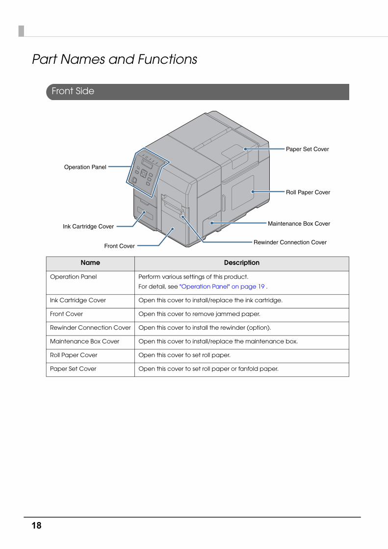
Front Side
Name Description
Operation Panel Perform various settings of this product.
For detail, see "Operation Panel" on page 19 .
Ink Cartridge Cover Open this cover to install/replace the ink cartridge.
Front Cover Open this cover to remove jammed paper.
Rewinder Connection Cover Open this cover to install the rewinder (option).
Maintenance Box Cover Open this cover to install/replace the maintenance box.
Roll Paper Cover Open this cover to set roll paper.
Paper Set Cover Open this cover to set roll paper or fanfold paper.
Ink Cartridge Cover
Operation Panel
Front CoverRewinder Connection Cover
Maintenance Box Cover
Roll Paper Cover
Paper Set Cover

19
Chapter 1 Product Overview
1
Operation Panel
Name Description
(Power) LED Lights when the printer is powered on.
Flashes during printing or ink charging.
Pause LED Lights/Flashes while the printer is paused.
Status LED Lights/Flashes in blue when the printer is operating properly.
Lights/Flashes in amber when the printer has an error.
Paper LED Lights when the printer has no paper or jammed paper, or when the Paper Set Cover, the Roll Paper Cover, or the Front Cover is open.
Ink LED Flashes in the following conditions:
Ink is low.
The maintenance box is nearly full.
Lights in the following conditions:
The ink cartridge cover/maintenance box cover is open.
No ink cartridge/maintenance box is set.
It is time to replace the ink cartridge/maintenance box.
LCD Displays the menus and messages.
See "Ink Cartridge and Maintenance Box Status" on page 31
Pause Button Press this button during printing to pause printing after one page of data is printed.
Press this button while the printer is paused (while the Pause LED is on) to resume printer operation and have the printer return to the print standby status.
Status Pause
Pause
Cancel
Menu
OK
Paper Ink
K C YM M/B
Back Feed
Feed
Cut
Back Feed Button
Ink LED
Paper LED
Feed Button
Cut Button
Selection/Setting Button
Cancel Button
Pause Button
LCD
Status LED
(Power) Button
Pause LED
(Power) LED
20
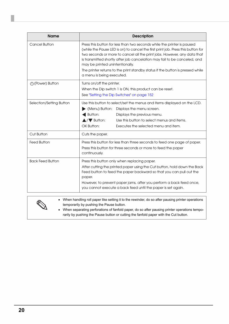
Cancel Button Press this button for less than two seconds while the printer is paused (while the Pause LED is on) to cancel the first print job. Press this button for two seconds or more to cancel all the print jobs. However, any data that is transmitted shortly after job cancelation may fail to be canceled, and may be printed unintentionally.
The printer returns to the print standby status if the button is pressed while a menu is being executed.
(Power) Button Turns on/off the printer.
When the Dip switch 1 is ON, this product can be reset.
See "Setting the Dip Switches" on page 152
Selection/Setting Button Use this button to select/set the menus and items displayed on the LCD.
(Menu) Button: Displays the menu screen.
Button: Displays the previous menu.
/ Button: Use this button to select menus and items.
OK Button: Executes the selected menu and item.
Cut Button Cuts the paper.
Feed Button Press this button for less than three seconds to feed one page of paper.
Press this button for three seconds or more to feed the paper continuously.
Back Feed Button Press this button only when replacing paper.
After cutting the printed paper using the Cut button, hold down the Back Feed button to feed the paper backward so that you can pull out the paper.
However, to prevent paper jams, after you perform a back feed once, you cannot execute a back feed until the paper is set again.
When handling roll paper like setting it to the rewinder, do so after pausing printer operations
temporarily by pushing the Pause button.
When separating perforations of fanfold paper, do so after pausing printer operations tempo-
rarily by pushing the Pause button or cutting the fanfold paper with the Cut button.
Name Description

21
Chapter 1 Product Overview
1
Rear Side
Name Description
USB Connector For connecting a USB cable.
Ethernet Connector For connecting a LAN cable.
Wire Saddle Pass the USB cable through this saddle to prevent disconnection of the USB cable.
AC Inlet For connecting a power cable.
Air Vent Exhausts heat generated in the product to prevent an internal temperature rise. Allow a clearance of 10 cm {3.94”} or more from the air vent to ensure ventilation when installing the product.
Dip Switch Cover mounting screw
Remove the screw to open the Dip Switch Cover.
Dip Switch Used when changing the function of the Power button.
Dip Switch Cover When operating the Dip Switch, remove the Dip Switch Cover Mounting Screw and open the cover.
When setting the Power button operation to "Power switch disabled (Reset operation)", make
sure the printer is not operating when turning the power OFF.
USB Connector
Ethernet Connector
Wire Saddle
AC Inlet
Air Vent
Dip Switch Cover
Dip Switch
Dip Switch Cover mounting screw

22
Nozzle Verification TechnologyThis product has an "Nozzle Verification Technology” that detects missing dots. You can select the “Nozzle Verification Technology Enable / Disable”, “Nozzle check interval” and/or “Threshold of clogged nozzles”, depending on level of requirement for missing dots.
And when unrecoverable clogging occurs, this printer is able to carry out supplemental printing using a nearby nozzle.
If you set “Enable” for the nozzle clog auto supplement system, it will be possible to remedy a marked fall in print quality and barcode quality due to an irrecoverably clogged nozzle.
Setting the Nozzle Verification Technology
If you set “Enable” for the Nozzle Verification Technology, in the cases described below or every time the number of printed copies in "Setting Nozzle check interval" has been reached, an auto nozzle check will be performed.
• Starting a printing job or per printed sheets specified in the interval of Nozzle check interval
• Power is turned ON
• The maintenance box cover is closed
• The roll paper cover or paper set cover is closed after a paper jam.
If the number of nozzle dropouts that is detected exceeds the “Threshold of clogged nozzles” that you have set, auto head cleaning will be executed to eliminate dot dropout.
Perform a nozzle check even after auto cleaning, and if the number of dropouts does not fall below the set “Threshold of clogged nozzles“, perform auto cleaning again.
CAUTION
This Nozzle Verification Technology cannot detect 100% of dot missing cases. It cannot detect
100% of missing dots and ink droplet curvature.
Print head maintenance is executed for all heads simultaneously. It is not executed only for
the heads and ink in which nozzle clogging was detected.
The Nozzle Verification Technology uses a small amount of ink.
After detecting a missing dot, cleaning is performed automatically and ink is also used in the
cleaning.

23
Chapter 1 Product Overview
1
Setting the Nozzle Verification Technology Enable / DisableEnable / Disable of Nozzle Verification Technology is set.
The factory setting is “Enable”.
Settings
It can be set from the setting menu of the product and PrinterSetting.
See "Setting panel switch" on page 82 or "PrinterSetting" on page 89
Setting Nozzle check intervalEvery time the number of printed copies has been reached, the printing operation will be stopped temporarily and the device will perform an auto nozzle check.
Settings
It can be set from the setting menu of the product and PrinterSetting.
Able to set in the unit of pages from 1 to 500
See "Setting panel switch" on page 82 or "PrinterSetting" on page 89
Setting Threshold of clogged nozzlesSet the allowable number of nozzle dropouts when executing a Nozzle Verification Technology. When the number of nozzle dropouts exceeds the value, a head cleaning is executed.
If the number of clogged nozzles does not reach this value, the dot substitution function is activated instead of performing head cleaning.
Settings
It can be set from the setting menu of the product and PrinterSetting.
Can be set between 0 to 10 nozzles
See "Setting panel switch" on page 82 or "PrinterSetting" on page 89
The allowable number of nozzle dropouts is the total for the nozzles for all four colors (CMYK).
The value initially set for the allowable number of nozzle dropouts is "6".
24
Dot substitution
The dot substitution is a function that performs complementary printing using the nearby nozzles when nozzles are clogged.
The maximum number of clogged nozzles that can be automatically supplemented is 16. However, supplementation cannot be performed adequately in the case of clogging of an adjacent nozzle.
Note that in the case of more than 16 clogged nozzles, supplementation for 16 nozzles will be implemented. After that, printing can continue.
This function does not become enabled even when setting the dot substitution to enable if the Nozzle Verification Technology is disabled.
Settings
It can be set from the setting menu of this product and PrinterSetting.
The factory setting is "On".
See "Setting panel switch" on page 82 or "PrinterSetting" on page 89
This function does not completely remedy falls in print quality, barcode quality and so forth.
This system carries out supplementation according to nozzle dropout information known at
the start of printing, and therefore is not able to supplement nozzle dropout that occurs
during printing.

25
Chapter 1 Product Overview
1
Periodic auto cleaningA periodic auto cleaning can be executed to maintain the printer heads in good condition.
A periodic auto cleaning takes 2 to 30 minutes. No printing can be performed during the cleaning.
You can set the time for implementation of periodic auto cleaning.
If periodic auto cleaning implementation time setting is disabled, periodic auto cleaning will be implemented at a time that the printer judges necessary, for example when a fixed time has elapsed since the previous periodic auto cleaning.
If the power is off at the time you set, the periodic auto cleaning will be implemented the next
time the power is turned on.
Periodic auto cleaning may sometimes be implemented when the power is turned on after
having been off for an extended period.
26
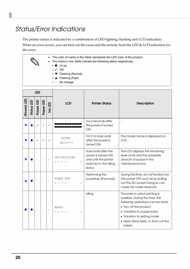
Status/Error IndicationsThe printer status is indicated by a combination of LED lighting/flashing and LCD indication.
When an error occurs, you can find out the cause and the remedy from the LED & LCD indication for the error.
The color of marks in the Table represents the LED color of the product.
The marks in the Table indicate the following status respectively.
●: Lit up
✓: Off
▼: Flashing (Normal)
▲: Flashing (Fast)
- : No change
LED
LCD Printer Status Description
(Pow
er)
LED
Sta
tus
LED
Paus
e L
ED
Pap
er L
ED
Ink
LED
▼ ● ✓ ✓ ✓■■■■■■■■■■■■■■■■
■■■■■■■■■■■■■■■■
For 2 seconds after the power is turned ON
-
▼ ● ✓ ✓ ✓ EPSON
TM-C****
For 2 to 4 seconds after the power is turned ON
The model name is displayed on LCD.
▼ ● - - -INITIALIZING
* * * * *
4 seconds after the power is turned ON and until the printer switches to the idling status
The LCD displays the remaining level of ink and the available amount of space in the maintenance box.
▲ ● - - -POWER OFF
* * * * *
Performing the powering off process
During this time, do not forcibly turn the power OFF, such as by pulling out the AC power Doing so can cause ink nozzle dropouts.
● ● - - -READY
* * * * *
Idling The state in which printing is possible. During the time, the following operations can be done.
Turn off the product
Transition to pause status
Transition to setting mode
Feed, Back feed, or Auto cut the paper

27
Chapter 1 Product Overview
1
● ● - - -POWER SAVING
* * * * *
Idling (with power saving)
If the product does not operate for 30 minutes or more while the power is ON, it moves to the power saving mode.
▼ ● - - -PRINTING
* * * * *
Printing A beep sounds when printing is done.
▼ ● - - -WORKING
* * * * *
After printing is done, the printer moves to idling
● - ● - -PAUSE
* * * * *
Pause When the Pause button is pushed during printing, the printer becomes this status.
It is possible to go to the setting mode from this state.
● ✓ - - -MENU
* * * * *
Menu When the Menu button is pushed, the printer becomes this status.
● - ● - -CANCELING JOB
* * * * *
Canceling the jobs When the Cancel button is pushed during printing, print jobs are canceled, printing is interrupted and print data inside the printer are deleted.
● ● - - -
PRINTING-NOZZLE
CHECK DISABLED
* * * * *
Nozzle Verification Technology is disable(*)
When dot dropouts cannot be detected due to low environmental temperature, the LCD display shows a message. Printing continues.
● ● - - -NOZZLE CLOGGED
* * * * *
Unrecoverable nozzle dropouts happen (*)
This display is shown when unrecoverable nozzle dropouts happen. Printing continues.
● ● ● - -
NOZZLE CLOGGED
CHECK THE PRINT
PRESS PAUSE
TO CONTINUE
Nozzle clogged (*) Printing is paused temporarily, since nozzle dropouts happened during printing. Printing restarts when the Pause button is pushed. When canceling printing, push and hold the CANCEL button for two seconds or more before pushing the Pause button.
button and button switch the LCD display.
LED
LCD Printer Status Description
(Pow
er)
LED
Sta
tus
LED
Paus
e L
ED
Pap
er L
ED
Ink
LED

28
● ▼ ● - -ROLL COVER OPEN
* * * * *
Roll paper cover open error (*)
The Roll paper cover is open.
● ▼ ● - -FRONT COVER OPEN
* * * * *
Front cover open error (*)
The Front cover is open.
● ▼ ● - -PAPER COVER OPEN
* * * * *
Paper cover open error (*)
The Paper set cover is open.
● ▼ ● - ●M/B COVER OPEN
* * * * *
Maintenance box cover open error (*)
The Maintenance box cover is open.
● ▼ ● - ●
INK CARTRIDGE
COVER OPEN
* * * * *
Ink cartridge cover open error (*)
The Ink cartridge cover is open.
● ▼ ● ● -
MEDIA DETECTION
ERROR
* * * * *
Media detection error (*)
The printer media detector's setting and the media in the printer are different.
button can be used to move to the setting mode and set the media detector.
● ▼ ● ● -MEDIA FORM ERROR
* * * * *
Media form error (*) The media type settings of the printer and the media in the printer are different.
button can be used to move to the setting mode and set the media type.
● - - ● -NO PAPER
* * * * *
No paper (*) No paper is available.
● ▼ ● ● -MEDIA SIZE ERROR
* * * * ## *
Media size error (*) The media size settings of the printer and the size of the media in the printer are different.
● ▼ ● ● -NO PAPER ERROR
* * * * *
No paper error (*) No paper is available.
● ▼ ● ● -PAPER JAM ERROR
* * * * ## *
Paper jam error (*) The paper is jammed.
● ▼ ● ● -
PAPER REMOVAL
ERROR
* * * * *
Paper removal error (*)
Printing ended when the last edge is removed from the core during printing.
Jobs still printing end and then the paper removal error occurs.
LED
LCD Printer Status Description
(Pow
er)
LED
Sta
tus
LED
Paus
e L
ED
Pap
er L
ED
Ink
LED

29
Chapter 1 Product Overview
1
● - - - -CUT UNAVAILABLE
* * * * *
In cutter unavailable state (*)
Autocutting is being performed 2 or more times with the paper in the same position.
● ▼ ● - ●NO INK CARTRIDGE
* * * * *
No ink cartridge (*) An ink cartridge is not equipped.
▼ ● - - -INK CHARGING
* * * * *
Ink charging Performing ink charging (initial charge).
Caution: Do not turn this product's power OFF until it is finished.
▼ ● - - -HEAD MAINTENANCE
* * * * *
Executing ink sequence
Printer head maintenance is being executed.
Caution: Do not turn this product's power OFF until it is finished.
● - - - ▼
INK CARTRIDGE
NEAR EMPTY
* * * * *
Ink level low (*) The level of ink indicated in the LCD display is low and ink cartridges need to be changed soon. Printing is possible.
● ▼ ● - ●
INK CARTRIDGE
EMPTY
* * * * *
Ink cartridge needs to be replaced (*)
The ink cartridges indicated in the LCD display need to be changed. Check the target ink on the LCD screen.
● ▼ ● - ●
INK CARTRIDGE
READ ERROR
* * * * *
Ink cartridge CSIC error (*)
The ink cartridge information could not be read.
● - - - ●
NON-GENUINE
CARTRIDGE MAY
NOT PERFORM AT
OPTIMUM LEVEL
CONTINUE?
YES
CONTINUE?
NO
PLEASE USE
GENUINE EPSON
INK CARTRIDGE
* * * * *
Non-genuine cartridge (*)
Non-genuine ink cartridge is used.
● ▼ ● - ●NO M/B
* * * * *
Maintenance box not loaded (*)
The maintenance box is not loaded
LED
LCD Printer Status Description
(Pow
er)
LED
Sta
tus
LED
Paus
e L
ED
Pap
er L
ED
Ink
LED
30
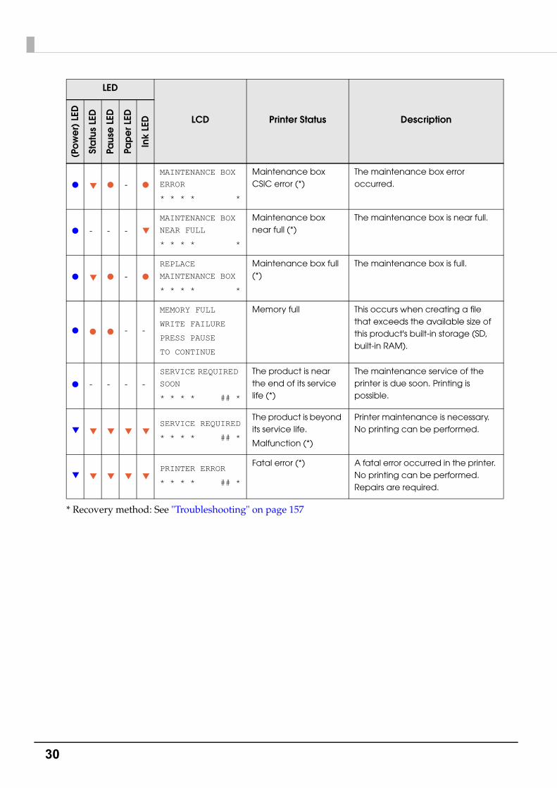
* Recovery method: See "Troubleshooting" on page 157
● ▼ ● - ●
MAINTENANCE BOX
ERROR
* * * * *
Maintenance box CSIC error (*)
The maintenance box error occurred.
● - - - ▼
MAINTENANCE BOX
NEAR FULL
* * * * *
Maintenance box near full (*)
The maintenance box is near full.
● ▼ ● - ●
REPLACE
MAINTENANCE BOX
* * * * *
Maintenance box full (*)
The maintenance box is full.
● ● ● - -
MEMORY FULL
WRITE FAILURE
PRESS PAUSE
TO CONTINUE
Memory full This occurs when creating a file that exceeds the available size of this product's built-in storage (SD, built-in RAM).
● - - - -
SERVICE REQUIRED
SOON
* * * * ## *
The product is near the end of its service life (*)
The maintenance service of the printer is due soon. Printing is possible.
▼ ▼ ▼ ▼ ▼SERVICE REQUIRED
* * * * ## *
The product is beyond its service life.
Malfunction (*)
Printer maintenance is necessary. No printing can be performed.
▼ ▼ ▼ ▼ ▼PRINTER ERROR
* * * * ## *
Fatal error (*) A fatal error occurred in the printer. No printing can be performed. Repairs are required.
LED
LCD Printer Status Description
(Pow
er)
LED
Sta
tus
LED
Paus
e L
ED
Pap
er L
ED
Ink
LED

31
Chapter 1 Product Overview
1
Ink Cartridge and Maintenance Box Status
You can check the status of the printer, the ink cartridges of each color, and the maintenance box from the LCD.
Display of the ink cartridge, maintenance box statusDisplays the status of ink cartridges and maintenance box with icons.
Icon Status
Display of amount remaining for the ink cartridge
Display of amount used for the maintenance box
Display for "Ink cartridge low"
Display for "Maintenance box near full"
Display for "Replace ink cartridge"
Display for "Replace maintenance box"
Display for "No ink cartridge"
Display for "Ink cartridge read error"
Display for "No maintenance box"
Display for "Maintenance box read area"
Amount used for the maintenance boxAmount remaining for the ink cartridge(black ink, cyan ink, magenta ink, yellow ink)
displays the status of the ink cartridges and maintenance box
Row 2:
displays the printer’s status
Row 1:

32
Beeper
The pattern of beeper sound is shown in the below table. The beeper continues to beep until all the causes of error are removed.
• Frequency: Fixed to approximately 2.5 kHz
• Volume control: 5 levels on the software (you can turn the sound off)
Sounding period
Silent period
Number of the
pattern repeated
Overall time
Number of times
repeatedPrinter event
500 ms 200 ms 5 6 secondsUntil the error
factor is removed.
Service required
Printer error
Replace ink cartridge
Replace maintenance box
Media form error
Media size error
Paper jam error
Paper removal error
Paper out error
100 ms 100 ms 5 1 second 1
Ink cartridge cover open
Maintenance box cover open
Paper set cover open
Roll paper cover open
Front cover open
Auto loading failure
Storage capacity over
No ink cartridge
No maintenance box
Ink cartridge read error
Maintenance box read error
1 second - None - 1 Printing finished
100 ms - None - 1
Operation panel sound vol-ume change
Auto loading successes

33
Chapter 2 Setup
2
SetupThis chapter describes the installation and setup of the product and peripherals necessary before using this product.
This product can be set up using the following methods.
• Perform setup following the Install Navi on the included CD-ROM. (page 34)Use the computer to start the Install Navi on the included CD-ROM and follow the procedure to set up this product.
• Setup this product without using the Install Navi. (page 36)

34
Install NaviBy using the Install Navi, this product can be set following the steps shown on the screen.
Unpacking and Installing the this product in advance. See the following for details.
• Checking the Items Included in the Package (page 37)
• Installing the Printer (page 38)
The setup procedure is as follows.
1 Turn on the computer.
2 Check that the product's power is OFF.
3 Insert the CD-ROM in your computer and the Launcher automatically starts.Click [Printer Setup] to start the Install Navi.
4 When the Install Navi is executed, the following screen is displayed. Agree to the SOFTWARE LICENSE AGREEMENT and click [Next]. Follow the instructions on the screen from here on to setup this product.
One of the setup steps of Install Navi is "Software installation" in which printer drivers, PrinterSetting and other software can be installed.
The product can be setup without installation. Also, the software can be installed later.
Make sure the printer's power is OFF.

35
Chapter 2 Setup
2
See the following if you are installing the rewinder.
• How to install the REWINDER (page 50)
• Attaching the paper leading edge to the rewinder (page 52)
This completes the setup of the product.

36
Work flow to set up this product without using the Install Navi
This chapter explains the installation and settings for this product and the peripherals necessary before using this product.
Please check the printing result depending on the environment after setup, you want to use.
3. Connecting the Power Cable (page 40)
2. Installing the Printer (page 38)
1. Checking the Items Included in the Package (page 37)
4. Connecting the Interface Cable (page 41)
5. Installing the Ink Cartridge (page 43)
8. Attaching the paper leading edge to the rewinder (page 52)
7. Setting the Paper (page 54)
9. Printer settings (page 65)
10. Paper settings (page 69)
11. Test printing (page 76)
Completing Setup
6. How to install the REWINDER (page 50)

37
Chapter 2 Setup
2
Checking the Items Included in the PackageWhen using the printer for the first time, check the items included in the package.
The items included in the package are as follows:
*1 It can be used for initial ink charging.
*2 This is required when re-shipping the product. Keep it in a safe place.
A TM-C7500 Series B Ink cartridge(C, M, Y, K)*1 C CD-ROM
D USB cable E Roll paper F AC cable
G Cushioning material *2
A B C D
E F
G

38
Installing the PrinterSecure sufficient space in a location appropriate for installation.
CAUTION
Two people are required to lift up this product.
The weight of this product is approximately 37 kg {81.57 lb}. When lifting up this product,
place the product between two people as shown in the figure below and hold the recessed
areas on both sides of the product. Carrying the product by holding other areas may
damage the product. When placing the product on the floor, be careful not to get your
fingers caught between the product and the installation surface.
Lift up this product in a natural posture, for example, bending your knees a sufficient
amount. Lifting the product in an inappropriate posture may cause injury to the worker or
damage to the product.
Do not tilt the product more than 10 degrees in any direction while carrying it. Doing so may
cause an accident.
When transporting this printer, do not put it upside down or topple over sideways.
Do not place anything that weighs more than 10 kg on top of the printer. The printer may be
damaged if an excessive force is applied.
Do not install the printer at a high location where it may fall during operations.
Do not install the printer at a location that is subject to vibration or impact. Make sure that
the printer is installed at a location that is not subject to vibration or impact during
operations. If vibration or impact was applied to the printer during operations, nozzle
verification may be performed repeatedly to avoid malfunction of the Nozzle Verification
Technology. When nozzle verification is performed repeatedly, it may take longer to process
the operations and throughput may decline.
While installing the printer, make sure that no cords or foreign objects are tucked under the
printer.
Be careful not to apply a strong impact to the printer during operations or processing as it
may affect printing.
39
Chapter 2 Setup
2
Location Appropriate for Installation
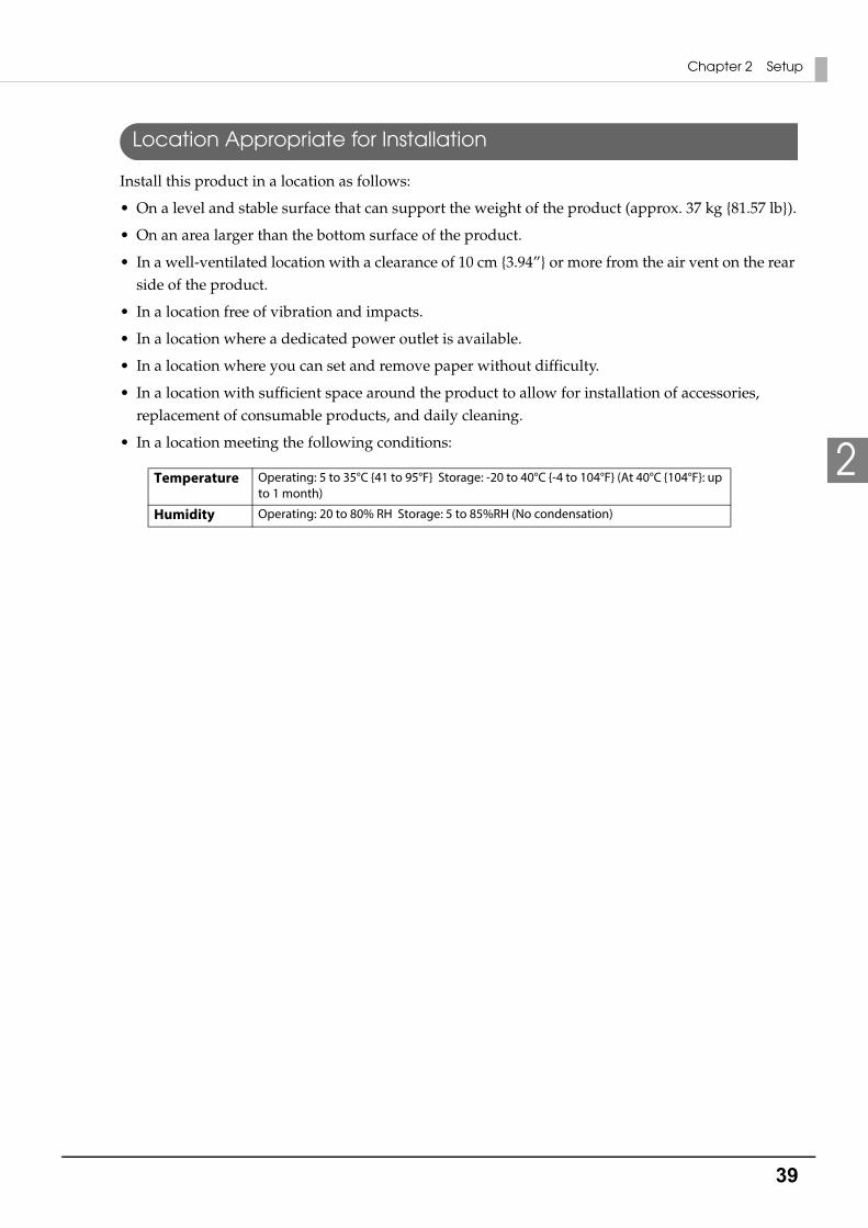
Install this product in a location as follows:
• On a level and stable surface that can support the weight of the product (approx. 37 kg {81.57 lb}).
• On an area larger than the bottom surface of the product.
• In a well-ventilated location with a clearance of 10 cm {3.94”} or more from the air vent on the rear side of the product.
• In a location free of vibration and impacts.
• In a location where a dedicated power outlet is available.
• In a location where you can set and remove paper without difficulty.
• In a location with sufficient space around the product to allow for installation of accessories, replacement of consumable products, and daily cleaning.
• In a location meeting the following conditions:
Temperature Operating: 5 to 35°C {41 to 95°F} Storage: -20 to 40°C {-4 to 104°F} (At 40°C {104°F}: up to 1 month)
Humidity Operating: 20 to 80% RH Storage: 5 to 85%RH (No condensation)
40
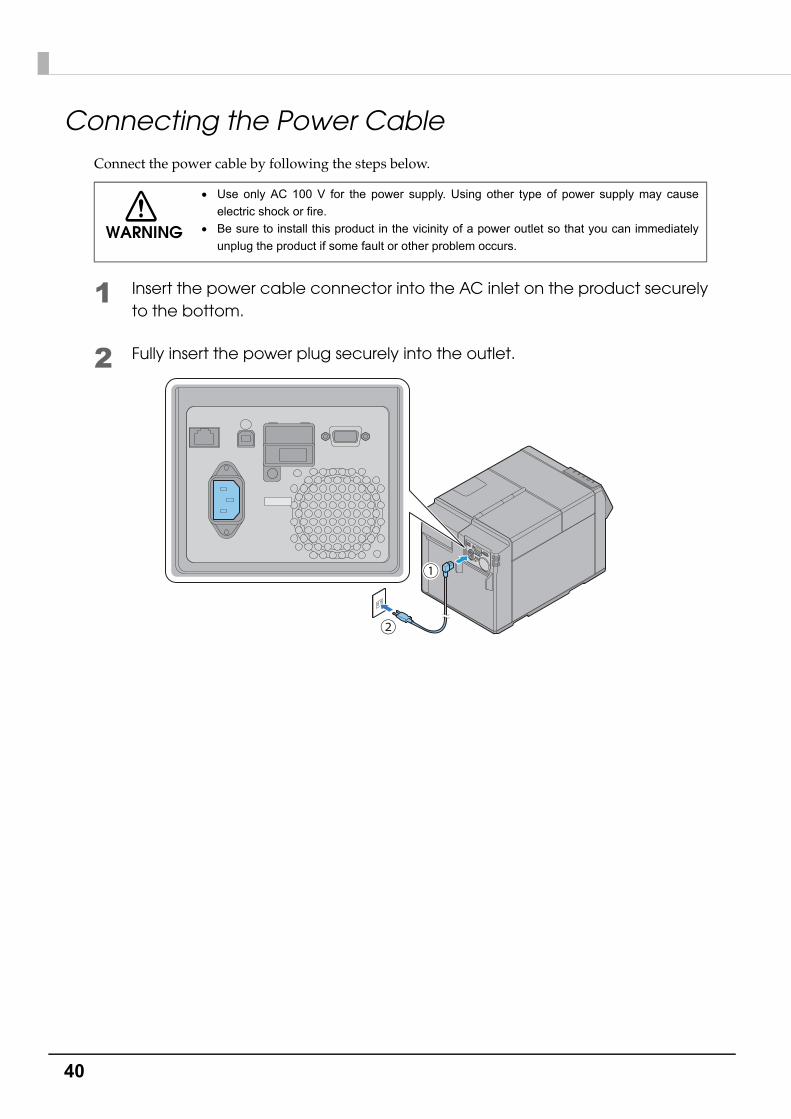
Connecting the Power CableConnect the power cable by following the steps below.
1 Insert the power cable connector into the AC inlet on the product securely to the bottom.
2 Fully insert the power plug securely into the outlet.
WARNING
Use only AC 100 V for the power supply. Using other type of power supply may cause
electric shock or fire.
Be sure to install this product in the vicinity of a power outlet so that you can immediately
unplug the product if some fault or other problem occurs.
41
Chapter 2 Setup
2
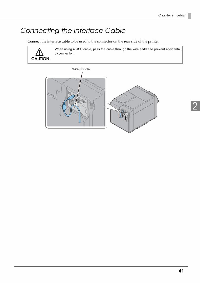
Connecting the Interface CableConnect the interface cable to be used to the connector on the rear side of the printer.
CAUTION
When using a USB cable, pass the cable through the wire saddle to prevent accidental
disconnection.
Wire Saddle

42
Turning On/OffThis section describes how to turn on/off the product.
Turning On
1 Press (Power) button.
2 (Power) LED lights up and the power turns on.
Turning Off
1 Hold down (Power) button for one second or more.
2 (Power) LED turns off and the power turns off.
43
Chapter 2 Setup
2
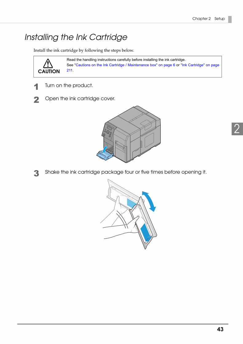
Installing the Ink CartridgeInstall the ink cartridge by following the steps below.
1 Turn on the product.
2 Open the ink cartridge cover.
3 Shake the ink cartridge package four or five times before opening it.
CAUTION
Read the handling instructions carefully before installing the ink cartridge.
See "Cautions on the Ink Cartridge / Maintenance box" on page 6 or "Ink Cartridge" on page
211.
44
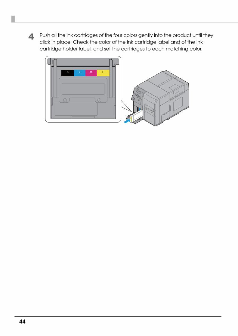
4 Push all the ink cartridges of the four colors gently into the product until they click in place. Check the color of the ink cartridge label and of the ink cartridge holder label, and set the cartridges to each matching color.

45
Chapter 2 Setup
2
5 Close the ink cartridge cover.
6 Press the Pause button.Ink charging starts. The (Power) LED flashes during ink charging.
7 When ink charging completes, the (Power) LED changes from flashing to on.
CAUTION
Never open any cover on the product or turn off the product during ink charging (while the
(Power) LED is flashing). Doing so during ink charging will consume a large amount of ink,
which may require replacement of the ink cartridge before completion of charging.
The ink cartridge included in the product package is used for initial charging. The printer uses
ink to prepare for printing when the ink cartridge is installed for the first time.
It takes at least 10 minutes to charge ink. The ink charging time varies depending on the
conditions.

46
Replacing the ink cartridgeAs the product is being used, the status of the ink cartridge changes as shown below.
• INK LOW
• REPLACE INK
INK LOW
When the ink level in the ink cartridge becomes low, the Ink LED flashes and [INK LOW] is displayed on LCD.
When "INK LOW" is displayed, prepare to replace the ink cartridge.
The number of printable papers that can be printed before the status changes from "INK LOW" to "REPLACE INK" depends on usage conditions.
REPLACE INK
When there is no ink in the ink cartridge, the Ink LED is lit, [REPLACE INK] is displayed on LCD and the product changes to offline.
Change to an ink cartridge with enough ink level using the following steps.
1 Check that the Ink LED is ON. Also, check the ink cartridge to be replaced with the LCD display.
2 Open the ink cartridge cover.
3 Push the ink cartridge to be replaced slowly. After making sure that its lock is unlocked, pull the ink cartridge out toward you.
4 Shake the ink cartridge package four or five times before opening it.
5 Push the ink cartridge into the product slowly until you hear the click sound.
6 Close the ink cartridge cover.
7 When replacement of the ink cartridge is complete, the Ink LED becomes OFF.
8 The product switches to the pause state. Push the Pause button to release it, and the product returns to the idle state.
When [INK LOW LED] is set to not be displayed, the Ink LED does not flash.
47
Chapter 2 Setup
2
Installing the Maintenance boxThe Maintenance box is already installed when the product is shipped.
Replacing Maintenance BoxWhile using the product, waste ink is collected in the Maintenance box. The status of the Maintenance box is shown as follows.
• MB NEAR FULL
• REPLACE MB
MB NEAR FULL
When the ink level in the ink cartridge becomes low, Ink LED flashes and [MB NEAR FULL] is displayed on the LCD.
When "MB NEAR FULL" is displayed, prepare to replace the maintenance box.
The number of papers that can be printed before status changes from "MB NEAR FULL" to "REPLACE MB" depends on usage conditions.
CAUTION
Read the handling instructions carefully before installing the Maintenance box.
See "Cautions on the Ink Cartridge / Maintenance box" on page 6.
When [INK LOW LED] is set to not be displayed, the Ink LED does not flash.

48
REPLACE MB
When there is almost no space that can be used in the Maintenance box, the Ink LED is lit, [REPLACE MB] is displayed on LCD and the product changes to offline.
Change to a Maintenance box with enough space using the following steps.
1 Check that the INK LED on the printer is lit up, and check that the maintenance box displays "REPLACE MAINT B" on the LCD.
2 Open the maintenance box cover towards you.
3 Pull out the used maintenance box towards you.
49
Chapter 2 Setup
2
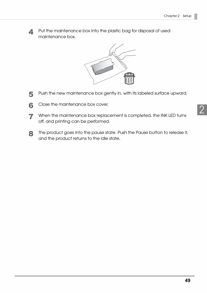
4 Put the maintenance box into the plastic bag for disposal of used maintenance box.
5 Push the new maintenance box gently in, with its labeled surface upward.
6 Close the maintenance box cover.
7 When the maintenance box replacement is completed, the INK LED turns off, and printing can be performed.
8 The product goes into the pause state. Push the Pause button to release it, and the product returns to the idle state.
50
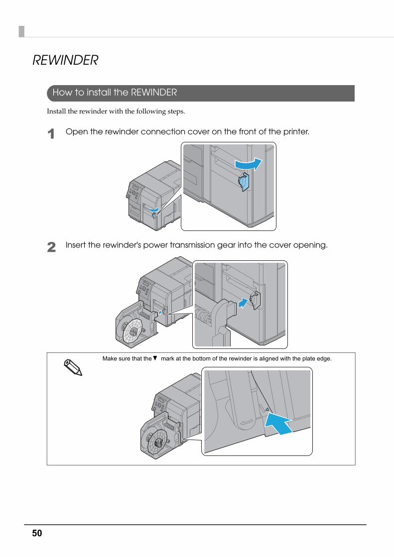
REWINDER
How to install the REWINDER
Install the rewinder with the following steps.
1 Open the rewinder connection cover on the front of the printer.
2 Insert the rewinder's power transmission gear into the cover opening.
Make sure that the mark at the bottom of the rewinder is aligned with the plate edge.

51
Chapter 2 Setup
2
Removing the rewinder
Pull the rewinder's lever in the direction of the arrow below, and remove the rewinder from the printer.

52
Attaching the paper leading edge to the rewinder
Attach the paper to the rewinder with the following steps.
1 Remove the rewinder's flange.
2 Press the Feed button and bring out approx. 800 mm {31.50"} of paper from this product.
3 Pass the paper under the roller and onto the rewinder, as in the figure below.
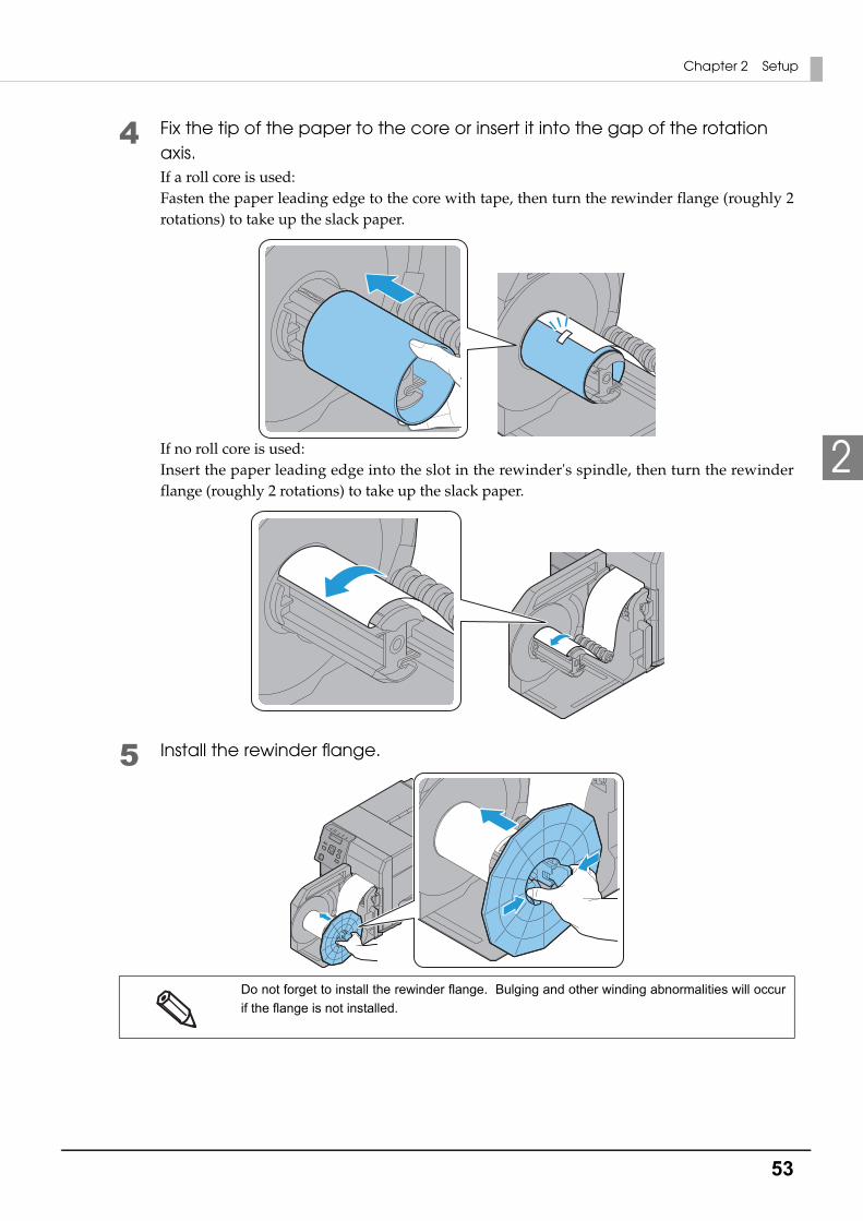
53
Chapter 2 Setup
2
4 Fix the tip of the paper to the core or insert it into the gap of the rotation axis.If a roll core is used:Fasten the paper leading edge to the core with tape, then turn the rewinder flange (roughly 2 rotations) to take up the slack paper.
If no roll core is used:Insert the paper leading edge into the slot in the rewinder's spindle, then turn the rewinder flange (roughly 2 rotations) to take up the slack paper.
5 Install the rewinder flange.
Do not forget to install the rewinder flange. Bulging and other winding abnormalities will occur
if the flange is not installed.

54
Setting the Paper
Setting the Roll Paper
Set the roll paper by following the steps below.
1 Turn on the product.
2 Open the paper set cover.
3 Open the roll paper cover.
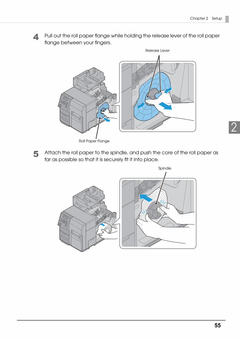
55
Chapter 2 Setup
2
4 Pull out the roll paper flange while holding the release lever of the roll paper flange between your fingers.
5 Attach the roll paper to the spindle, and push the core of the roll paper as far as possible so that it is securely fit it into place.
Roll Paper Flange
Release Lever
Spindle
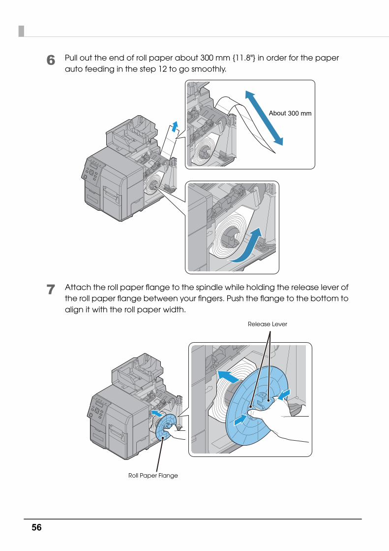
56
6 Pull out the end of roll paper about 300 mm {11.8"} in order for the paper auto feeding in the step 12 to go smoothly.
7 Attach the roll paper flange to the spindle while holding the release lever of the roll paper flange between your fingers. Push the flange to the bottom to align it with the roll paper width.
300 mmAbout
Roll Paper Flange
Release Lever
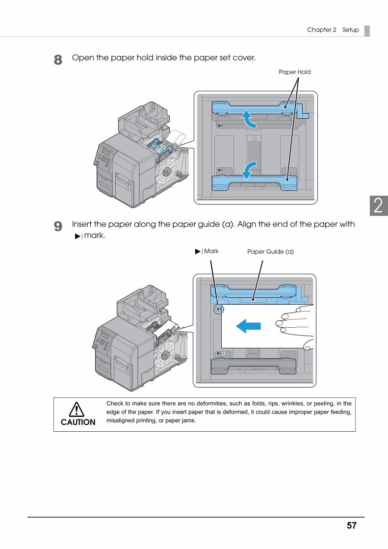
57
Chapter 2 Setup
2
8 Open the paper hold inside the paper set cover.
9 Insert the paper along the paper guide (a). Align the end of the paper with mark.
CAUTION
Check to make sure there are no deformities, such as folds, rips, wrinkles, or peeling, in the
edge of the paper. If you insert paper that is deformed, it could cause improper paper feeding,
misaligned printing, or paper jams.
Paper Hold
Paper Guide (a)Mark

58
10Hold down the paper so it does not move around. Move the paper guide (b) to align it with the paper width while pushing the paper guide (b) lever.
11Adjust the guide panel of the paper guide (b) so that it aligns perfectly with the edge of the paper.
Lever Paper Guide (b)
Guide panelPaper Guide (b)
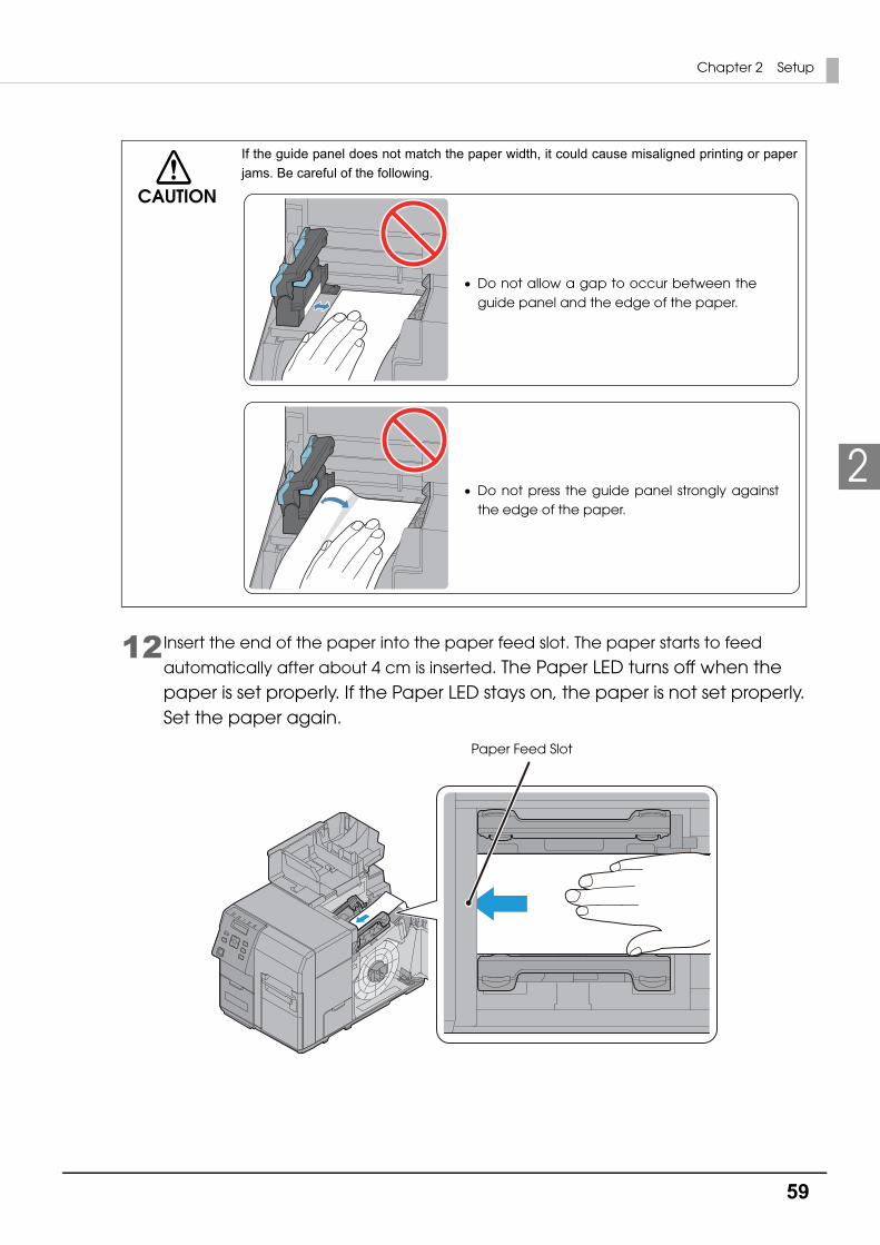
59
Chapter 2 Setup
2
12Insert the end of the paper into the paper feed slot. The paper starts to feed
automatically after about 4 cm is inserted. The Paper LED turns off when the paper is set properly. If the Paper LED stays on, the paper is not set properly. Set the paper again.
CAUTION
If the guide panel does not match the paper width, it could cause misaligned printing or paper
jams. Be careful of the following.
Do not allow a gap to occur between the guide panel and the edge of the paper.
Do not press the guide panel strongly against the edge of the paper.
Paper Feed Slot
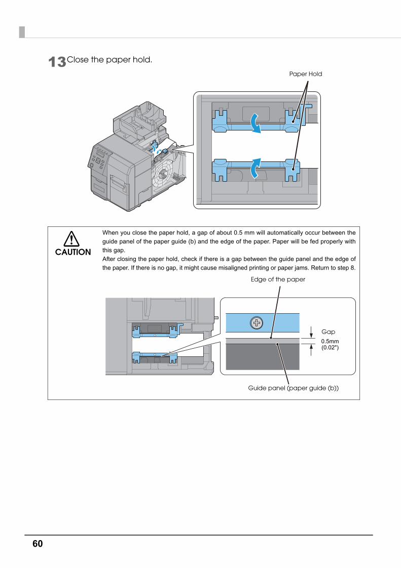
60
13Close the paper hold.
CAUTION
When you close the paper hold, a gap of about 0.5 mm will automatically occur between the
guide panel of the paper guide (b) and the edge of the paper. Paper will be fed properly with
this gap.
After closing the paper hold, check if there is a gap between the guide panel and the edge of
the paper. If there is no gap, it might cause misaligned printing or paper jams. Return to step 8.
Paper Hold
(0.02")0.5mm
Edge of the paper
Guide panel (paper guide (b))
Gap
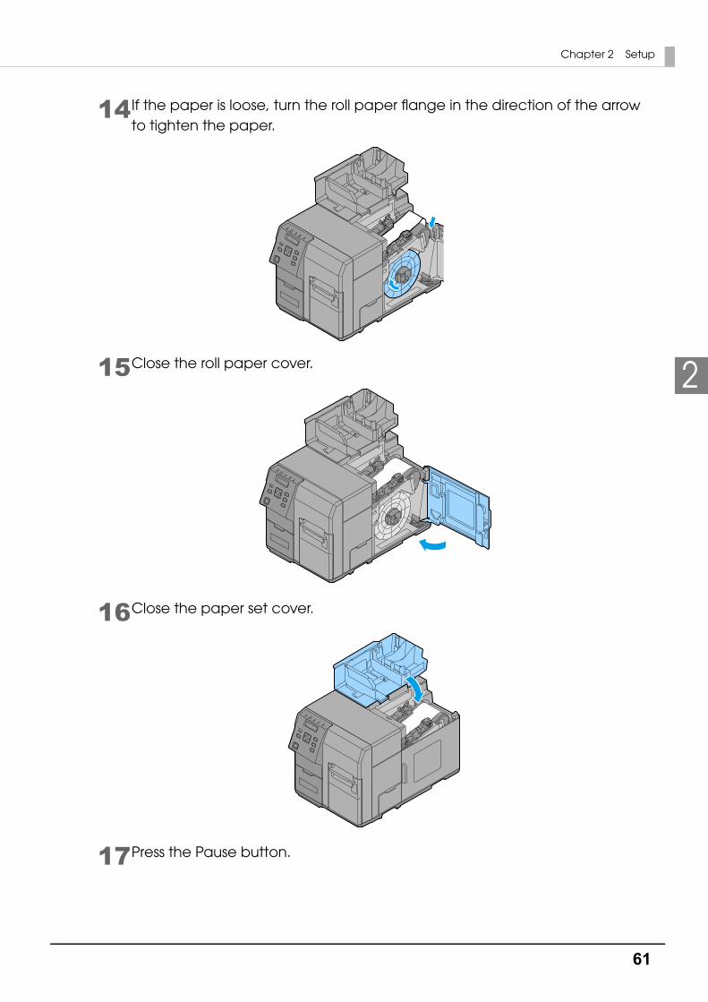
61
Chapter 2 Setup
2
14If the paper is loose, turn the roll paper flange in the direction of the arrow to tighten the paper.
15Close the roll paper cover.
16Close the paper set cover.
17Press the Pause button.

62
Setting the Fanfold Paper
Set the fanfold paper by following the steps below.
1 Turn on the product.
2 Open the paper set cover.
3 Set the fanfold paper referring to Step 8 to 12 in " Setting the Roll Paper".
4 Close the paper set cover.
5 Place the fanfold paper straight 15 mm or more away from the rear side of the product. Also, for the paper width direction, match it to the standard marking on the rear side of the product.
6 Press the Pause button.
15 mm { }0.59”
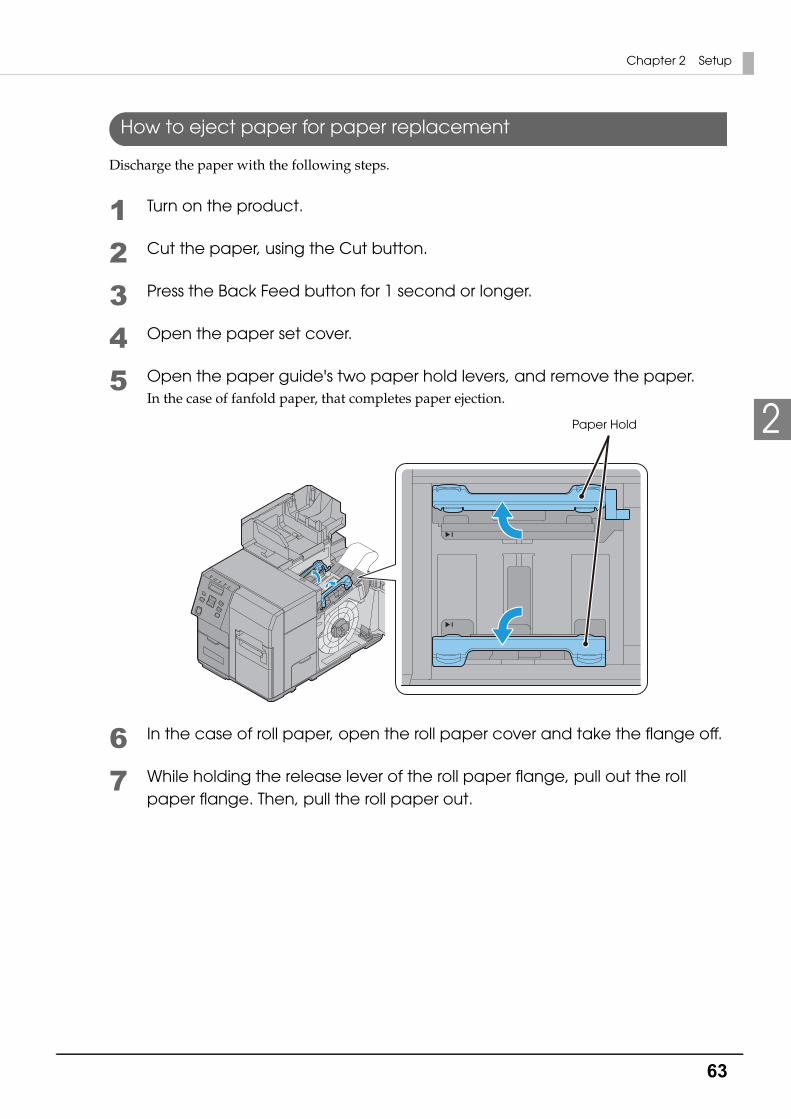
63
Chapter 2 Setup
2
How to eject paper for paper replacement
Discharge the paper with the following steps.
1 Turn on the product.
2 Cut the paper, using the Cut button.
3 Press the Back Feed button for 1 second or longer.
4 Open the paper set cover.
5 Open the paper guide's two paper hold levers, and remove the paper.In the case of fanfold paper, that completes paper ejection.
6 In the case of roll paper, open the roll paper cover and take the flange off.
7 While holding the release lever of the roll paper flange, pull out the roll paper flange. Then, pull the roll paper out.
Paper Hold
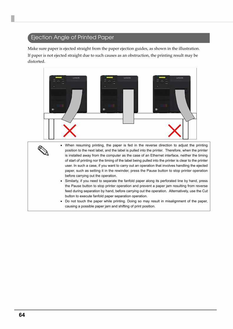
64
Ejection Angle of Printed Paper
Make sure paper is ejected straight from the paper ejection guides, as shown in the illustration.
If paper is not ejected straight due to such causes as an obstruction, the printing result may be distorted.
When resuming printing, the paper is fed in the reverse direction to adjust the printing
position to the next label, and the label is pulled into the printer. Therefore, when the printer
is installed away from the computer as the case of an Ethernet interface, neither the timing
of start of printing nor the timing of the label being pulled into the printer is clear to the printer
user. In such a case, if you want to carry out an operation that involves handling the ejected
paper, such as setting it in the rewinder, press the Pause button to stop printer operation
before carrying out the operation.
Similarly, if you need to separate the fanfold paper along its perforated line by hand, press
the Pause button to stop printer operation and prevent a paper jam resulting from reverse
feed during separation by hand, before carrying out the operation. Alternatively, use the Cut
button to execute fanfold paper separation operation.
Do not touch the paper while printing. Doing so may result in misalignment of the paper,
causing a possible paper jam and shifting of print position.

65
Chapter 2 Setup
2
Printer settingsVarious settings of the product can be done from the menu screen. This section explains basic setting procedures.
Language Setting
Set the language used for the messages displayed on the LCD by following the steps below.
1 Turn on the product.
2 Press the (Menu) button to display the menu.
3 Select [PRINTER SETUP3] and press the OK button.
4 Select [LANGUAGE] and press the OK button.
5 Select the language to be used. The following languages are available:
Japanese
English
French
German
Dutch
Italian
Spanish
Portuguese
6 Press the OK button. This completes language setting.
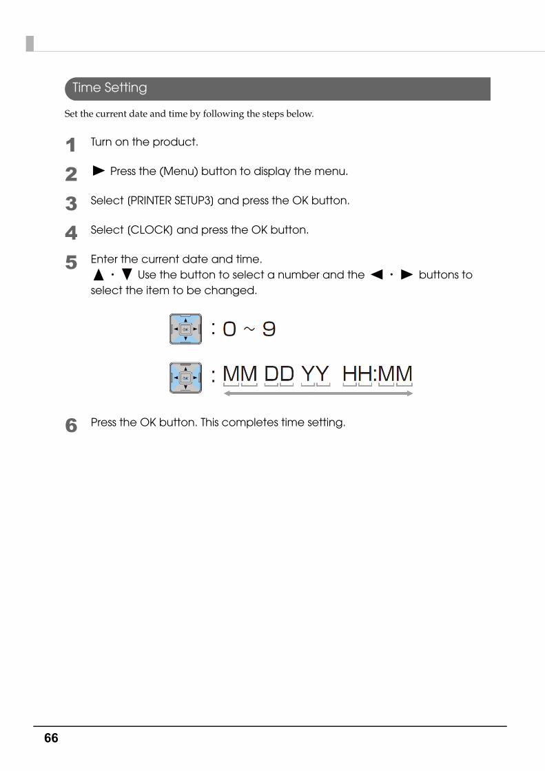
66
Time Setting
Set the current date and time by following the steps below.
1 Turn on the product.
2 Press the (Menu) button to display the menu.
3 Select [PRINTER SETUP3] and press the OK button.
4 Select [CLOCK] and press the OK button.
5 Enter the current date and time. Use the button to select a number and the buttons to
select the item to be changed.
6 Press the OK button. This completes time setting.

67
Chapter 2 Setup
2
Network settings
Set the IP address of the product following the steps below.
1 Turn on the product.
2 Press the (Menu) button to display the menu.
3 Select [I/F SETUP] and press the OK button.
4 Select [NETWORK SETUP] and press the OK button.
5 Select [IP ADDRESS] and press the OK button.
6 Select [AUTO] or [MANUAL].When [AUTO] is selected, the network settings are complete.When [MANUAL] is selected, go to Step 7 and set IP address, etc.
7 Select [IP ADDRESS] and press the OK button.
8 Enter the IP address. Use the button to select a number and the buttons to
select the digit to be changed.
When using the product with an Ethernet connection, it is necessary to setup the network.
When using with a USB connection, network settings are not necessary.
When performing network settings, obtain the necessary information from a network
administrator.
The network setting can be checked by printing the status sheet.See "Printing the status sheet (Network settings)" on page 86.

68
9 Press the OK button.
10Select [SUBNET MASK] and press the OK button.
11Enter the Subnet mask.For the input method, refer to the input of the IP address in Step 8.
12Press the OK button.
13Select [DEFAULT GATEWAY] and press the OK button.
14Enter the Default gateway.For the input method, refer to the input of the IP address in Step 8.
15Press the OK button.

69
Chapter 2 Setup
2
Paper settingsThe media source, media type, media form and media detection are set.
• When using a Windows driver:See "Set using a printer driver" on page 69
• When not using a Windows driver:See "Setting using the PrinterSetting" on page 72
• When setting up in an environment not connected to a computer:See "Setting with the operation panel" on page 75
Set using a printer driver
1 Turn on the product.
2 Display the printer driver window.See "How to Display the Printer Driver" on page 78
3 Click [Media Detection].

70
4 The "Media Detection Settings" screen is displayed. Select the Media source and Media Detection, and click [OK].
5 Click [User Defined].
6 The "User Defined Media Layout" screen is displayed.
7 Enter Media Layout Name.If there is an existing defined media layout, you can create a new layout based on the defined media layout.
8 Select [Media Form].

71
Chapter 2 Setup
2
9 Enter the size of the paper (unit: mm).
10Click [Add]. User Defied Media will be registered and displayed on the list of [Defined Media Layout].
11Click [Close].
12From [Media Layout], select the newly created media layout.
13Select [Media Coating Type].
14Click [OK].
This completes the settings of media source, media coating type, media form and media detection.
When enlarging the print area, put a checkmark in [Borderless Printing] to eliminate margins.When the margins are zero, the print may extend outside of the media/label. Use it accordingly.
When [Borderless Printing] is checked, [Feather Edges] can be checked.When [Feather Edges] is checked, gradation processing is performed on the margin areas.
For TM-C7500, glossy paper is not displayed

72
Setting using the PrinterSetting
1 Turn on the product.
2 Start PrinterSetting.See "Starting the PrinterSetting" on page 90
3 The "Media settings" screen is displayed.
4 Set the Media source/Media detection/Media coating type. Click [Apply settings].

73
Chapter 2 Setup
2
5 From the items on the left, select [Layout settings]. Click [Edit layout...].
6 The "User Defined Media Layout" screen is displayed.
7 Enter Media Layout Name.If there is an existing defined media layout, you can create a new layout based on the defined media layout.
8 Select [Media Form].

74
9 Enter the size of the paper (unit: mm).
10Click [Add]. User Defied Media will be registered and displayed on the list of [Defined Media Layout].
11Click [Close].
12From [Media Layout], select the newly created media layout.
13Click [Apply Settings].
This completes the settings of media source, media coating type, media form and media detection.
When enlarging the print area, put a checkmark in [Borderless Printing] to eliminate margins.When the margins are zero, the print may extend outside of the media/label. Use it accordingly.
When [Borderless Printing] is checked, [Feather Edges] can be checked.When [Feather Edges] is checked, gradation processing is performed on the margin areas.
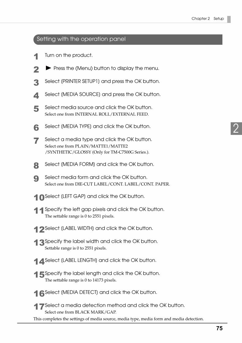
75
Chapter 2 Setup
2
Setting with the operation panel
1 Turn on the product.
2 Press the (Menu) button to display the menu.
3 Select [PRINTER SETUP1] and press the OK button.
4 Select [MEDIA SOURCE] and press the OK button.
5 Select media source and click the OK button.Select one from INTERNAL ROLL/EXTERNAL FEED.
6 Select [MEDIA TYPE] and click the OK button.
7 Select a media type and click the OK button.Select one from PLAIN/MATTE1/MATTE2/SYNTHETIC/GLOSSY (Only for TM-C7500G Series.).
8 Select [MEDIA FORM] and click the OK button.
9 Select media form and click the OK button.Select one from DIE-CUT LABEL/CONT. LABEL/CONT. PAPER.
10Select [LEFT GAP] and click the OK button.
11Specify the left gap pixels and click the OK button.The settable range is 0 to 2551 pixels.
12Select [LABEL WIDTH] and click the OK button.
13Specify the label width and click the OK button.Settable range is 0 to 2551 pixels.
14Select [LABEL LENGTH] and click the OK button.
15Specify the label length and click the OK button.The settable range is 0 to 14173 pixels.
16Select [MEDIA DETECT] and click the OK button.
17Select a media detection method and click the OK button.Select one from BLACK MARK/GAP.
This completes the settings of media source, media type, media form and media detection.
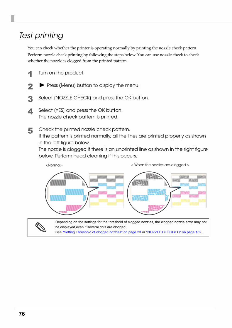
76
Test printingYou can check whether the printer is operating normally by printing the nozzle check pattern.
Perform nozzle check printing by following the steps below. You can use nozzle check to check whether the nozzle is clogged from the printed pattern.
1 Turn on the product.
2 Press (Menu) button to display the menu.
3 Select [NOZZLE CHECK] and press the OK button.
4 Select [YES] and press the OK button. The nozzle check pattern is printed.
5 Check the printed nozzle check pattern.If the pattern is printed normally, all the lines are printed properly as shown in the left figure below.The nozzle is clogged if there is an unprinted line as shown in the right figure below. Perform head cleaning if this occurs.
Depending on the settings for the threshold of clogged nozzles, the clogged nozzle error may not
be displayed even if several dots are clogged.
See "Setting Threshold of clogged nozzles" on page 23 or "NOZZLE CLOGGED" on page 162.
<Normal> < When the nozzles are clogged >

77
Chapter 2 Setup
2
Test Printing
If the printer driver has been installed already, a test printing can be performed.
Perform a test printing with the following steps.
1 Open the [Devices and Printers].
For Windows 8:Select [Control Panel] of Sidebar [Settings] on [Desktop], and click [Hardware and Sound], then [Devices and Printers].
For Windows 7:Click [View devices and printers] of [Control Panel] on [Start] menu.
For Windows Vista:Click [Printers] of [Control Panel] on [Start] menu.
For Windows XP Professional:Click [Printers and Faxes] on [Start] menu.
For Windows XP Home Edition:Click [Control Panel] on [Start] menu, and click [Printers and Faxes].
For Windows Server 2003 R2:Click [Printers and Faxes] on [Start] menu.
2 Right-click [EPSON TM-C7500], and click [Printer properties].
3 The Properties screen is displayed. Click [Print Test Page].
Registered name of this product to display in the case of the [EPSON TM-C7500].

78
How to Display the Printer Driver
1 Open the [Devices and Printers].
For Windows 8:Select [Control Panel] of Sidebar [Settings] on [Desktop], and click [Hardware and Sound], then [Devices and Printers].
For Windows 7:Click [View devices and printers] of [Control Panel] on [Start] menu.
For Windows Vista:Click [Printers] of [Control Panel] on [Start] menu.
For Windows XP Professional:Click [Printers and Faxes] on [Start] menu.
For Windows XP Home Edition:Click [Control Panel] on [Start] menu, and click [Printers and Faxes].
For Windows Server 2003 R2:Click [Printers and Faxes] on [Start] menu.
2 Right-click [EPSON TM-C7500], and click [Printing References].The printer driver screen is displayed.
Registered name of this product to display in the case of the [EPSON TM-C7500].
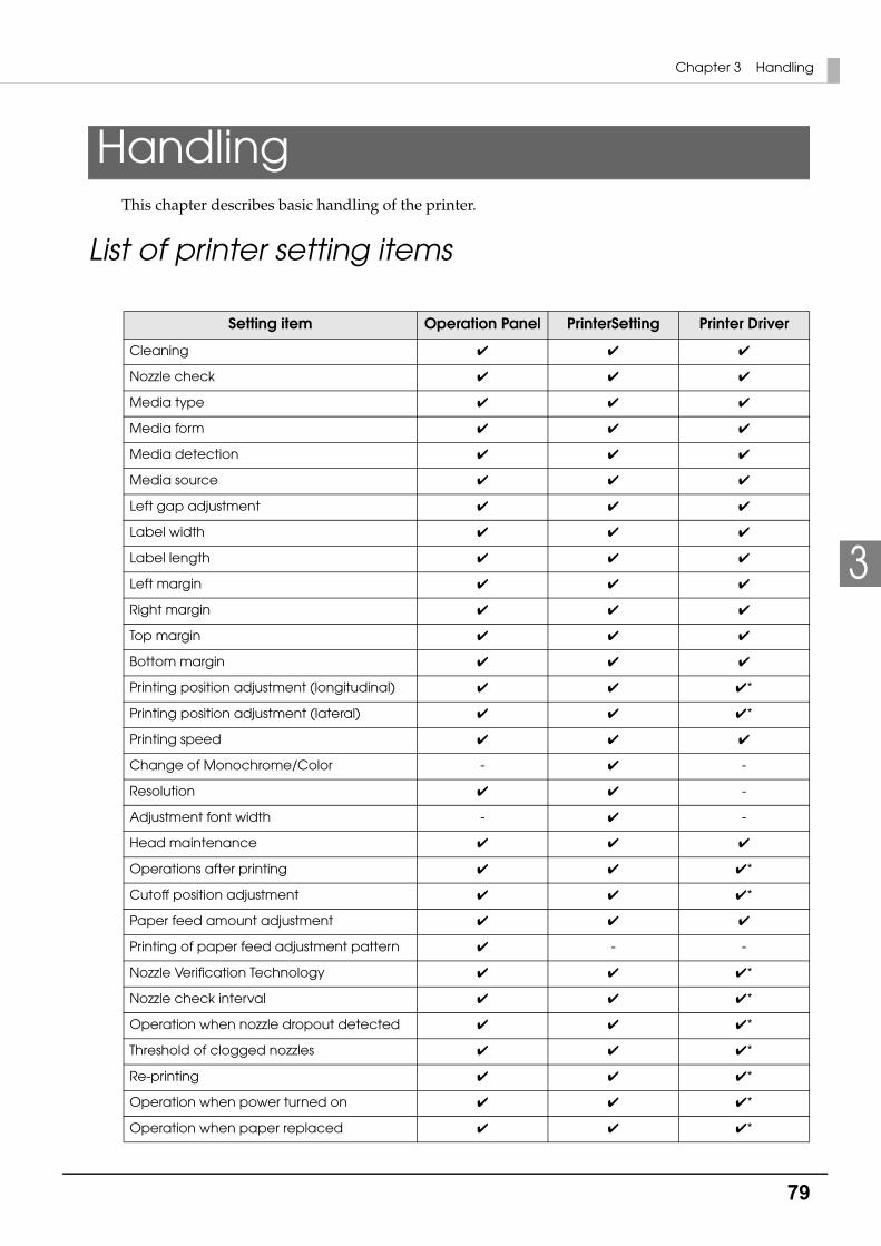
79
Chapter 3 Handling
3
HandlingThis chapter describes basic handling of the printer.
List of printer setting items
Setting item Operation Panel PrinterSetting Printer Driver
Cleaning ✔ ✔ ✔
Nozzle check ✔ ✔ ✔
Media type ✔ ✔ ✔
Media form ✔ ✔ ✔
Media detection ✔ ✔ ✔
Media source ✔ ✔ ✔
Left gap adjustment ✔ ✔ ✔
Label width ✔ ✔ ✔
Label length ✔ ✔ ✔
Left margin ✔ ✔ ✔
Right margin ✔ ✔ ✔
Top margin ✔ ✔ ✔
Bottom margin ✔ ✔ ✔
Printing position adjustment (longitudinal) ✔ ✔ ✔*
Printing position adjustment (lateral) ✔ ✔ ✔*
Printing speed ✔ ✔ ✔
Change of Monochrome/Color - ✔ -
Resolution ✔ ✔ -
Adjustment font width - ✔ -
Head maintenance ✔ ✔ ✔
Operations after printing ✔ ✔ ✔*
Cutoff position adjustment ✔ ✔ ✔*
Paper feed amount adjustment ✔ ✔ ✔
Printing of paper feed adjustment pattern ✔ - -
Nozzle Verification Technology ✔ ✔ ✔*
Nozzle check interval ✔ ✔ ✔*
Operation when nozzle dropout detected ✔ ✔ ✔*
Threshold of clogged nozzles ✔ ✔ ✔*
Re-printing ✔ ✔ ✔*
Operation when power turned on ✔ ✔ ✔*
Operation when paper replaced ✔ ✔ ✔*

80
Operation cancellation via panel ✔ - -
Specified-time cleaning ✔ ✔ ✔*
Time for specified-time TCL ✔ ✔ ✔*
LCD brightness ✔ ✔ ✔*
LCD contrast ✔ ✔ ✔*
Beeper volume ✔ ✔ ✔*
Ink low LED alert ✔ ✔ ✔*
Language settings ✔ ✔ ✔*
Date/Time ✔ ✔ ✔*
Control prefix characters ✔ ✔ -
Format prefix characters ✔ ✔ -
Delimiter characters ✔ ✔ -
Factory reset ✔ ✔ ✔*
Erase memory ✔ ✔ ✔*
Initialize I/F ✔ - -
Initialize media detection sensor ✔ - -
Color correction method ✔ ✔ ✔
Ink profile ✔ ✔ ✔
Ratio of black to composite ✔ ✔ ✔
Edge shading ✔ ✔ ✔
Nozzle dropout supplementation ✔ ✔ ✔*
Banding reduction ✔ ✔ ✔
Calibration ✔ ✔ ✔*
Ink recharging *1 ✔ - -
Printer data printing ✔ - -
Printing distance (non-resettable) display ✔ - -
Printer distance (resettable counter 1) display
✔ - -
Printer distance (resettable counter 2) display
✔ - -
Labels printed count (resettable counter 1) display
✔ - -
Labels printed count (resettable counter 2) display
✔ - -
Cumulative carriage motion count display ✔ - -
Auto cutter operation count display ✔ ✔ -
Firmware version display ✔ - -
IP setting ✔ - -
IP address ✔ - -
Setting item Operation Panel PrinterSetting Printer Driver
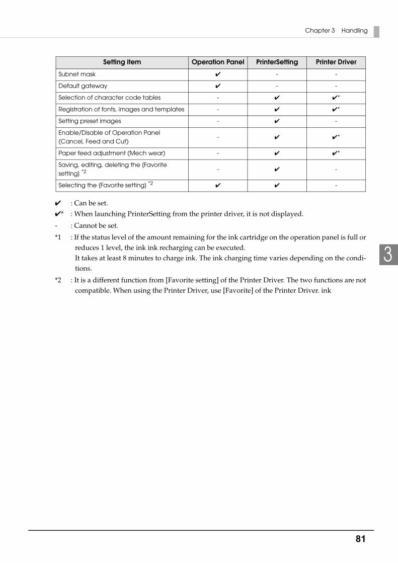
81
Chapter 3 Handling
3
✔ : Can be set.
✔* : When launching PrinterSetting from the printer driver, it is not displayed.
- : Cannot be set.
*1 : If the status level of the amount remaining for the ink cartridge on the operation panel is full or reduces 1 level, the ink ink recharging can be executed.It takes at least 8 minutes to charge ink. The ink charging time varies depending on the condi-tions.
*2 : It is a different function from [Favorite setting] of the Printer Driver. The two functions are not compatible. When using the Printer Driver, use [Favorite] of the Printer Driver. ink
Subnet mask ✔ - -
Default gateway ✔ - -
Selection of character code tables - ✔ ✔*
Registration of fonts, images and templates - ✔ ✔*
Setting preset images - ✔ -
Enable/Disable of Operation Panel (Cancel, Feed and Cut)
- ✔ ✔*
Paper feed adjustment (Mech wear) - ✔ ✔*
Saving, editing, deleting the [Favorite setting] *2 - ✔ -
Selecting the [Favorite setting] *2 ✔ ✔ -
Setting item Operation Panel PrinterSetting Printer Driver

82
Setting panel switch
Settings menu item Available settings Default setting
CLEANING YES
NO
-
NOZZLE CHECK YES
NO
-
PRINTER SETUP1 MEDIA TYPE PLAIN
MATTE1
MATTE2
SYNTHETIC
GLOSSY
MATTE2
MEDIA FORM DIE-CUT LABEL
CONT. LABEL
CONT. PAPER
DIE-CUT LABEL
MEDIA DETECT BLACK MARK
GAP
GAP
MEDIA SOURCE INTERNAL ROLL
EXTERNAL FEED
INTERNAL ROLL
LEFT GAP 0 to 2,551 [pixel] 47
LABEL WIDTH 0 to 2,551 [pixel] 2,551
LABEL LENGTH 0 to 14,173 [pixel] 3,600
LEFT MARGIN 0 to 35 [pixel] 35
RIGHT MARGIN 0 to 35 [pixel] 35
TOP MARGIN 0 to 35 [pixel] 35
BOTTOM MARGIN 0 to 35 [pixel] 35
V. POSITION 48 to -48 [pixel] 0
H. POSITION -24 to +24 [pixel] 0
PRINTING SPEED 150[mm/s]
300[mm/s]
150[mm/s]
RESOLUTION 600[dpi]
300[dpi]
200[dpi]
600[dpi]
HEAD MAINTENANCE PAUSE FOR MAINTENANCE
CONTINUOUS PRINTING
PAUSE FOR MAINTENANCE
PAPER HANDLING AFTER PRINT NO CUT
CUT
NO CUT

83
Chapter 3 Handling
3
PRINTER SETUP1 CUT POSITION -35 to +35 [pixel] 0
PAPER FEED ADJUSTMENT -99 to +99 0
PRINT PAPER FEED ADJ. PATTERN YES
NO
-
PRINTER SETUP2 NOZZLE VERIFICATION TECHNOLOGY ENABLE
DISABLE
ENABLE
NOZZLE CHECK INTERVAL 0 to 500 [sheets] 0 sheets
OPERATION AT CLOGGED NOZZLE CONTINUE
NOTIFY
CONTINUE
THRESHOLD OF CLOGGED NOZZLES 0 to 10 [nozzles] 6
REPRINT ENABLE
DISABLE
ENABLE
POWER ON ACTION FEED
CALIBRATION
NO FEED
FEED
PAPER CHANGE ACTION FEED
CALIBRATION
NO FEED
FEED
CANCEL ACTION JOB ONLY
JOB/RAM DRIVE
JOB ONLY
SCHEDULED CLEAN ENABLE
DISABLE
DISABLE
CLEANING TIME HH:MM (24-hour clock)
00:00
Settings menu item Available settings Default setting

84
PRINTER SETUP3 LCD BRIGHTNESS OFF
LEVEL1
LEVEL2
LEVEL3
LEVEL2
LCD CONTRAST 0 to 10 5
BEEPER VOLUME OFF
LOW
MEDIUM
HIGH
MAX
MEDIUM
INK LOW LED DISPLAY
NO DISPLAY
DISPLAY
LANGUAGE JAPANESE
ENGLISH
FRENCH
GERMAN
ITALIAN
SPANISH
PORTUGUESE
DUTCH
According to market destination
CLOCK MM/DD/YY HH:MM -
CONTROL PREFIX 0x00 to FF 0x7E
FORMAT PREFIX 0x00 to FF 0x5E
DELIMITER CHAR 0x00 to FF 0x2C
FACTORY RESET YES
NO
-
ERASE MEMORY YES
NO
-
INITIALIZE I/F YES
NO
-
INITIALIZE MEDIA DETECTION SENSOR YES
NO
-
Settings menu item Available settings Default setting
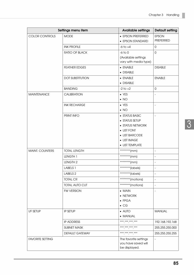
85
Chapter 3 Handling
3
COLOR CONTROLS MODE EPSON PREFERRED
EPSON STANDARD
EPSON PREFERRED
INK PROFILE -6 to +4 0
RATIO OF BLACK -6 to 0
(Available settings vary with media type)
0
FEATHER EDGES ENABLE
DISABLE
DISABLE
DOT SUBSTITUTION ENABLE
DISABLE
ENABLE
BANDING -2 to +2 0
MAINTENANCE CALIBRATION YES
NO
-
INK RECHARGE YES
NO
-
PRINT INFO STATUS BASIC
STATUS SETUP
STATUS NETWORK
LIST FONT
LIST BARCODE
LIST IMAGE
LIST TEMPLATE
-
MAINT. COUNTERS TOTAL LENGTH ********[mm] -
LENGTH 1 ********[mm] -
LENGTH 2 ********[mm] -
LABELS 1 ********[labels] -
LABELS 2 ********[labels] -
TOTAL CR ********[motions] -
TOTAL AUTO CUT ********[motions] -
FW VERSION MAIN
NETWORK
FPGA
CG
-
I/F SETUP IP SETUP AUTO
MANUAL
MANUAL
IP ADDRESS ***.***.***.*** 192.168.192.168
SUBNET MASK ***.***.***.*** 255.255.255.000
DEFAULT GATEWAY ***.***.***.*** 255.255.255.255
FAVORITE SETTING The favorite settings you have saved will be displayed.
-
Settings menu item Available settings Default setting
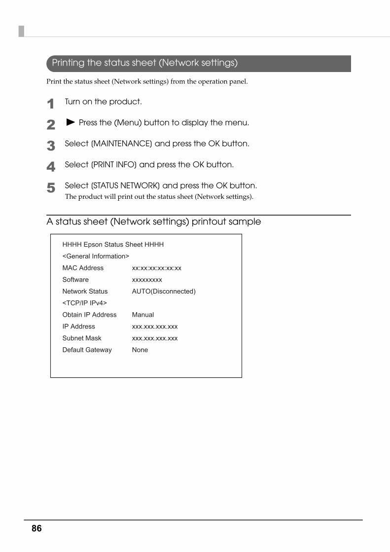
86
Printing the status sheet (Network settings)
Print the status sheet (Network settings) from the operation panel.
1 Turn on the product.
2 Press the (Menu) button to display the menu.
3 Select [MAINTENANCE] and press the OK button.
4 Select [PRINT INFO] and press the OK button.
5 Select [STATUS NETWORK] and press the OK button.The product will print out the status sheet (Network settings).
A status sheet (Network settings) printout sample
HHHH Epson Status Sheet HHHH
<General Information>
MAC Address
Software
Network Status
<TCP/IP IPv4>
Obtain IP Address
IP Address
Subnet Mask
Default Gateway
xx:xx:xx:xx:xx:xx
xxxxxxxxx
AUTO(Disconnected)
Manual
xxx.xxx.xxx.xxx
xxx.xxx.xxx.xxx
None
87
Chapter 3 Handling
3
Favorite
You can save settings such as the media type, the media size, the media source, media detection and the preset image in [Favorite setting] and register it to the product to easily apply them by selecting them on the operation panel.
You can save up to 100 items in [Favorite setting].
Operating environment• The settings in [Favorite setting] are only valid in the following cases:
when using printer drivers with ZPL II command to print from applications that support the ZPL II command
when printing through the direct command execution from applications developed by users
• This function is disabled when printing with TM-C7500/TM-C7500G Series printer drivers.
• You can use this function with the product firmware Ver.WAI30000 or later or with PrinterSetting Ver.1.2.0.0 or later.
Instructions for use
1 In PrinterSetting, save the [Favorite setting] settings to the product.See "Saving favorite settings" on page 108.
2 Make sure that the printer is not in the middle of the cleaning operation or printing operation, or that data is not being sent to the product.
3 In the [FAVORITE SETTING] menu on the LCD screen, select [Favorite setting] you have saved and click the OK button.See "FAVORITE SETTING" on page 85.The [Favorite setting] save names on the [Favorite setting] list appear in the ascending order.
4 After you have changed the settings, the message "CHANGE SUCCEEDED" will appear on the LCD screen for approximately 3 seconds.

88
Important points• If the [Media Detection] or [Media source] settings in [Favorite setting] are different from the
printer settings, a media detection error or a paper path error will occur. If that happens, refer to the "Troubleshooting" section, remove the error and configure [Favorite setting] again.
• You can select [Favorite setting] on the operation panel or in PrinterSetting.
• If the settings could not be configured, [PRINTER IS BUSY CHANGE FAILED] will appear for 3 seconds. Check the printer status again and reconfigure the settings.
• The application settings will be given priority over the settings in [Favorite setting] of the printer.
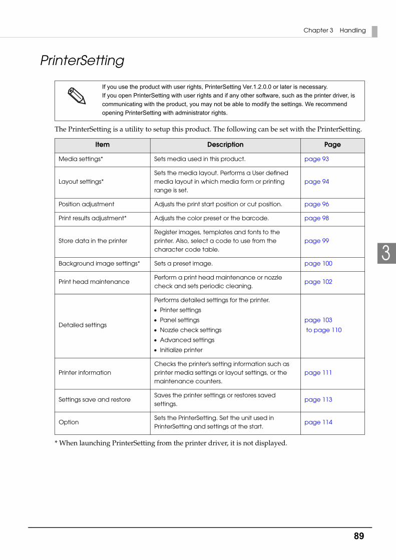
89
Chapter 3 Handling
3
PrinterSetting
The PrinterSetting is a utility to setup this product. The following can be set with the PrinterSetting.
* When launching PrinterSetting from the printer driver, it is not displayed.
If you use the product with user rights, PrinterSetting Ver.1.2.0.0 or later is necessary.
If you open PrinterSetting with user rights and if any other software, such as the printer driver, is
communicating with the product, you may not be able to modify the settings. We recommend
opening PrinterSetting with administrator rights.
Item Description Page
Media settings* Sets media used in this product. page 93
Layout settings*Sets the media layout. Performs a User defined media layout in which media form or printing range is set.
page 94
Position adjustment Adjusts the print start position or cut position. page 96
Print results adjustment* Adjusts the color preset or the barcode. page 98
Store data in the printerRegister images, templates and fonts to the printer. Also, select a code to use from the character code table.
page 99
Background image settings* Sets a preset image. page 100
Print head maintenancePerform a print head maintenance or nozzle check and sets periodic cleaning.
page 102
Detailed settings
Performs detailed settings for the printer.
Printer settings
Panel settings
Nozzle check settings
Advanced settings
Initialize printer
page 103
to page 110
Printer informationChecks the printer's setting information such as printer media settings or layout settings, or the maintenance counters.
page 111
Settings save and restoreSaves the printer settings or restores saved settings.
page 113
OptionSets the PrinterSetting. Set the unit used in PrinterSetting and settings at the start.
page 114

90
Starting the PrinterSetting
Start the PrinterSetting with the following methods.
1 Turn on the product.
2 Select [Start] - [All Programs] - [Epson] - [TM-C7500 Series] - [PrinterSetting].
3 The [Select printer] screen is displayed. Select a search target and click [Search].
4 This product is displayed in the list. Select a printer to set and click [OK].
For an Ethernet connection, the product may not be displayed when a search is executed.
In that case, enter IP address.

91
Chapter 3 Handling
3
5 Start the PrinterSetting.
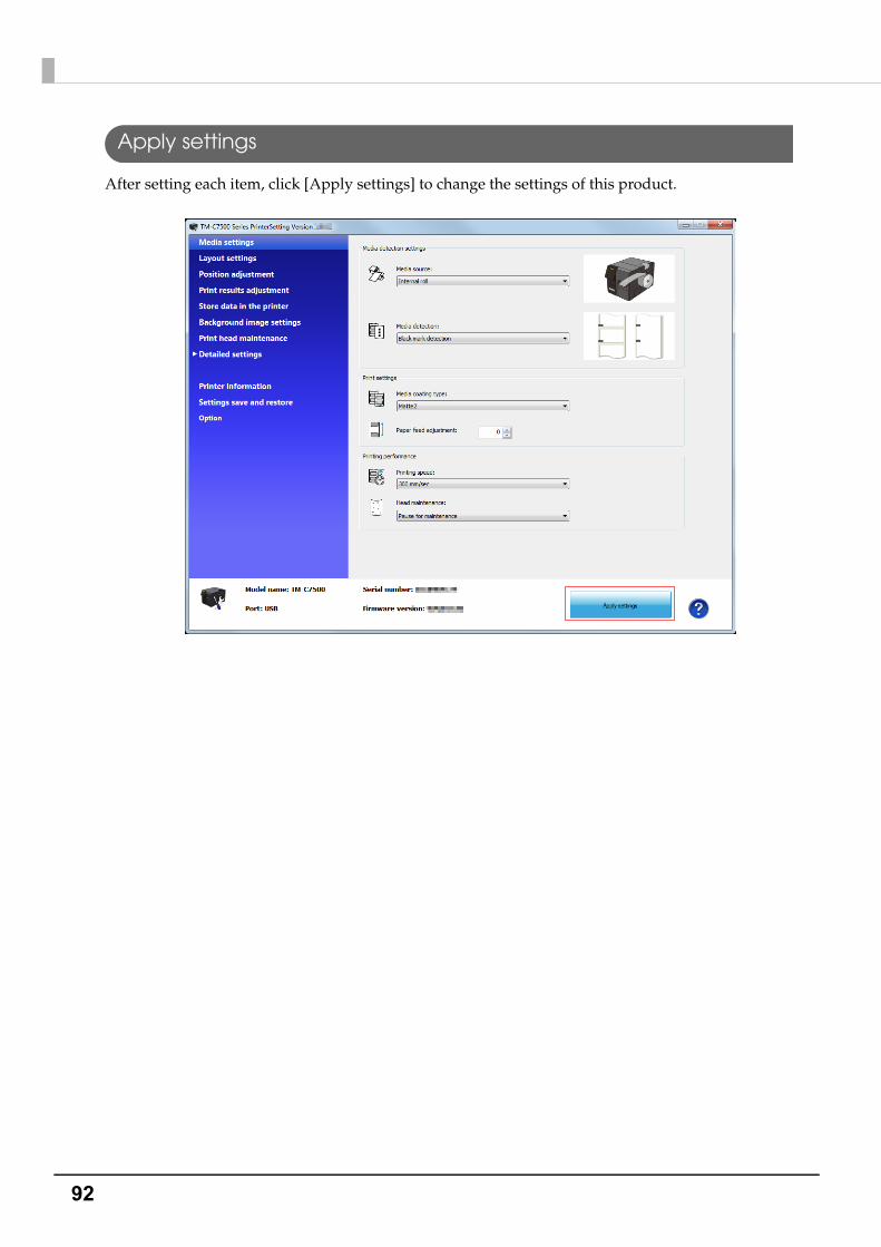
92
Apply settings
After setting each item, click [Apply settings] to change the settings of this product.
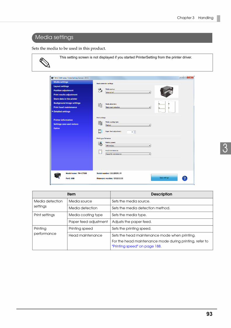
93
Chapter 3 Handling
3
Media settings
Sets the media to be used in this product.
This setting screen is not displayed if you started PrinterSetting from the printer driver.
Item Description
Media detection settings
Media source Sets the media source.
Media detection Sets the media detection method.
Print settings Media coating type Sets the media type.
Paper feed adjustment Adjusts the paper feed.
Printing performance
Printing speed Sets the printing speed.
Head maintenance Sets the head maintenance mode when printing.
For the head maintenance mode during printing, refer to "Printing speed" on page 188.

94
Layout settings
Sets the media layout or creates a new User defined media layout.
This setting screen is not displayed if you started PrinterSetting from the printer driver.
Item Description
Layout settings Media layout Sets the media layout.
Edit layout Creates a new user defined media layout. When clicked, the "Layout settings" screen is displayed.
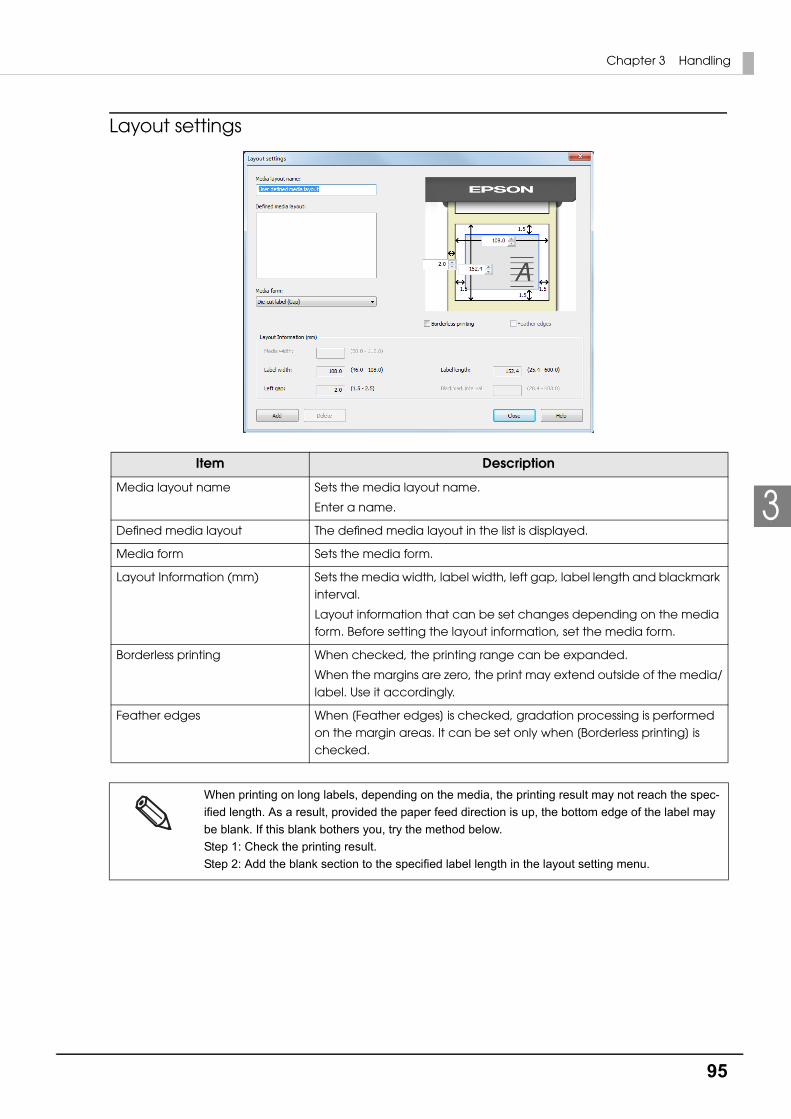
95
Chapter 3 Handling
3
Layout settings
Item Description
Media layout name Sets the media layout name.
Enter a name.
Defined media layout The defined media layout in the list is displayed.
Media form Sets the media form.
Layout Information (mm) Sets the media width, label width, left gap, label length and blackmark interval.
Layout information that can be set changes depending on the media form. Before setting the layout information, set the media form.
Borderless printing When checked, the printing range can be expanded.
When the margins are zero, the print may extend outside of the media/label. Use it accordingly.
Feather edges When [Feather edges] is checked, gradation processing is performed on the margin areas. It can be set only when [Borderless printing] is checked.
When printing on long labels, depending on the media, the printing result may not reach the spec-
ified length. As a result, provided the paper feed direction is up, the bottom edge of the label may
be blank. If this blank bothers you, try the method below.
Step 1: Check the printing result.
Step 2: Add the blank section to the specified label length in the layout setting menu.
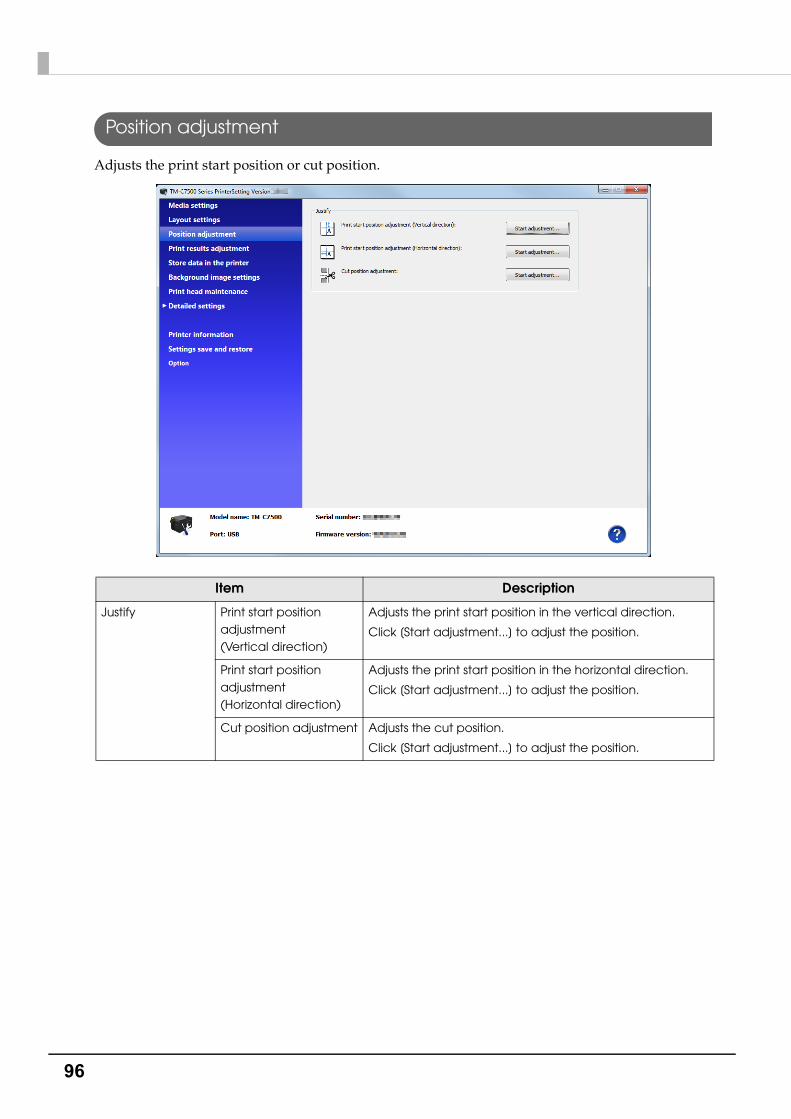
96
Position adjustment
Adjusts the print start position or cut position.
Item Description
Justify Print start position adjustment (Vertical direction)
Adjusts the print start position in the vertical direction.
Click [Start adjustment...] to adjust the position.
Print start position adjustment (Horizontal direction)
Adjusts the print start position in the horizontal direction.
Click [Start adjustment...] to adjust the position.
Cut position adjustment Adjusts the cut position.
Click [Start adjustment...] to adjust the position.

97
Chapter 3 Handling
3
Apply settings
1 Click [Start adjustment...] and the following screen is displayed.(Explained using the print start position adjustment (vertical direction) as an example.)
2 Enter the adjustment value and click [Apply settings].
3 The confirmation screen is displayed. Click [Yes] to execute the adjustment.
4 The results are displayed. Click [OK].
5 After executing the adjustment, perform printing and check the adjusted position.
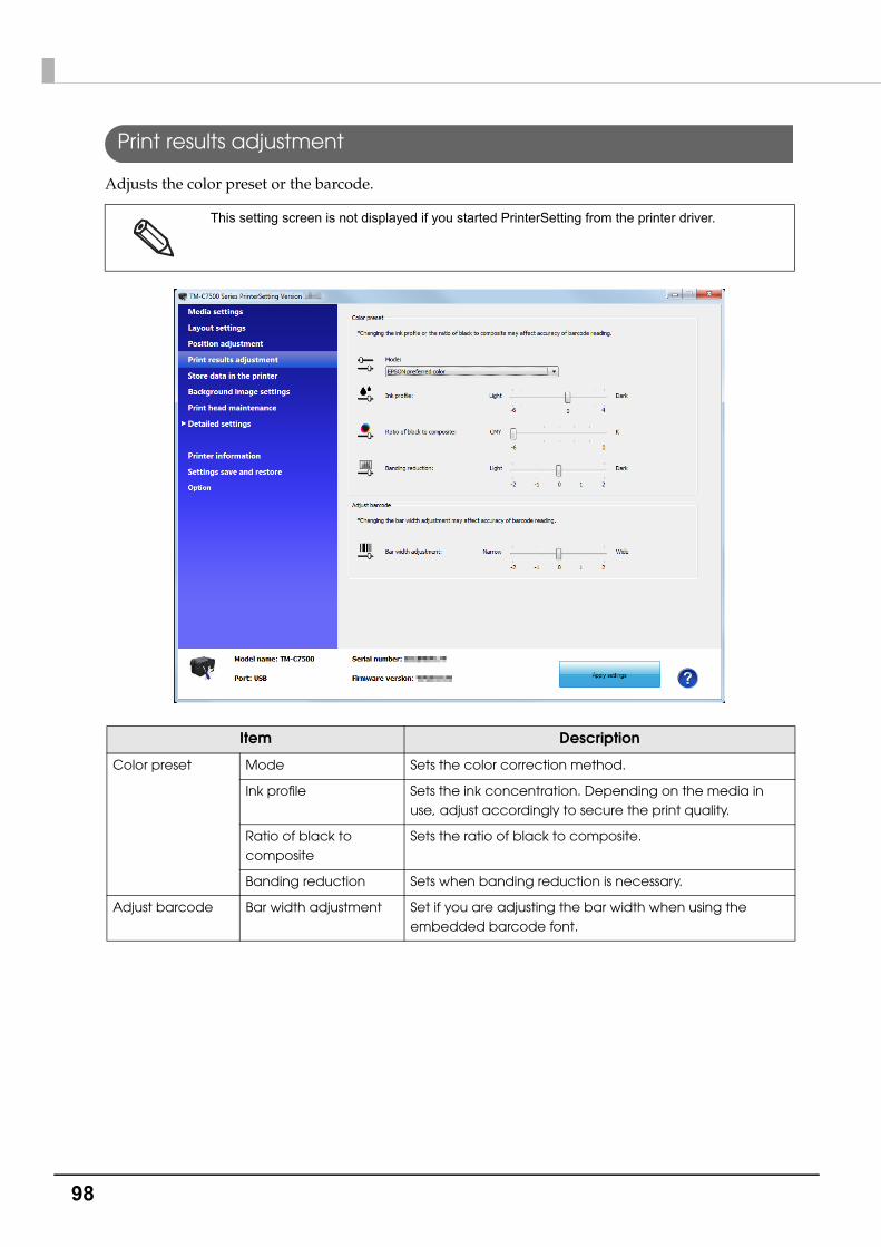
98
Print results adjustment
Adjusts the color preset or the barcode.
This setting screen is not displayed if you started PrinterSetting from the printer driver.
Item Description
Color preset Mode Sets the color correction method.
Ink profile Sets the ink concentration. Depending on the media in use, adjust accordingly to secure the print quality.
Ratio of black to composite
Sets the ratio of black to composite.
Banding reduction Sets when banding reduction is necessary.
Adjust barcode Bar width adjustment Set if you are adjusting the bar width when using the embedded barcode font.

99
Chapter 3 Handling
3
Store data in the printer
Registers images, templates, fonts, and character code tables to the printer.
Item Description
Image (Only .png) Registers an image used for preprinting or templates.
Template Registers a template.
Font (Only .ttf and .tte) Registers a font to apply to print data.
Character code table Changes the character code used for printing.

100
Background image settings
Sets a preset image.
Register a preset image in the following cases.
When using the Windows driver from Zebra Technologies Corporation.
When using the commercially available label printing application that supports this product.
When using an application that directly controls ZPL II or ESC/Label commands.
This setting screen is not displayed if you started PrinterSetting from the printer driver.
Item Description
Set background image
Do not use background image
The preset image is not printed.
Use shared background image
In case of regular printing, print the specified image as a preset image.
When printing using a template, the preset image is not printed.
Use different background images for each template
When printing using a template, the preset image is printed according to the specified combination.
When a template is not used, the preset image is not printed.
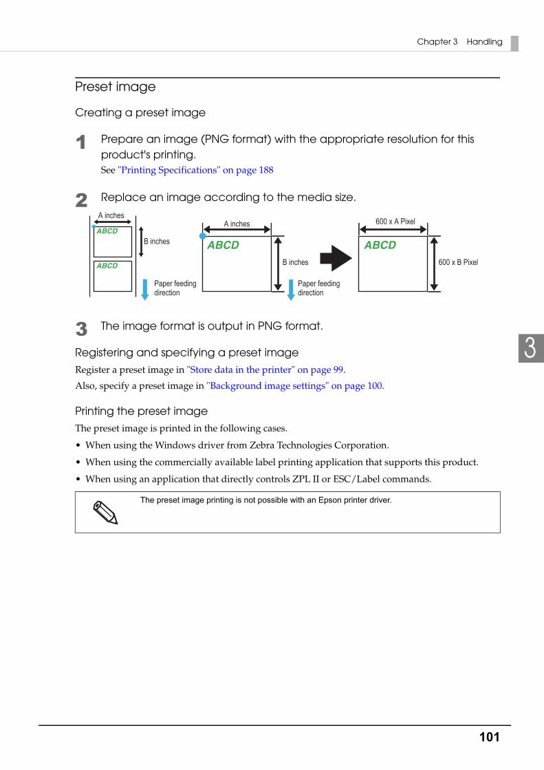
101
Chapter 3 Handling
3
Preset image
Creating a preset image
1 Prepare an image (PNG format) with the appropriate resolution for this product's printing.See "Printing Specifications" on page 188
2 Replace an image according to the media size.
3 The image format is output in PNG format.
Registering and specifying a preset image
Register a preset image in "Store data in the printer" on page 99.
Also, specify a preset image in "Background image settings" on page 100.
Printing the preset image
The preset image is printed in the following cases.
• When using the Windows driver from Zebra Technologies Corporation.
• When using the commercially available label printing application that supports this product.
• When using an application that directly controls ZPL II or ESC/Label commands.
The preset image printing is not possible with an Epson printer driver.
600 x A Pixel
600 x B Pixel
A inches
B inches
A inches
B inches
Paper feeding direction
Paper feeding direction
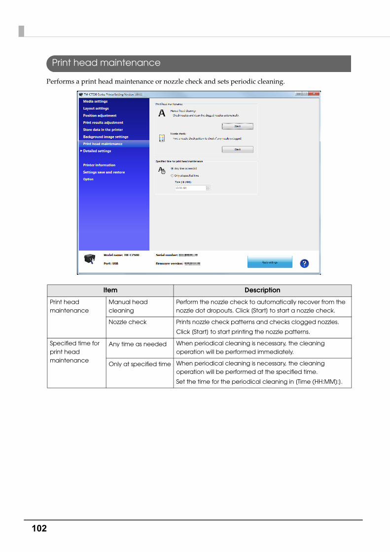
102
Print head maintenance
Performs a print head maintenance or nozzle check and sets periodic cleaning.
Item Description
Print head maintenance
Manual head cleaning
Perform the nozzle check to automatically recover from the nozzle dot dropouts. Click [Start] to start a nozzle check.
Nozzle check Prints nozzle check patterns and checks clogged nozzles.
Click [Start] to start printing the nozzle patterns.
Specified time for print head maintenance
Any time as needed When periodical cleaning is necessary, the cleaning operation will be performed immediately.
Only at specified time When periodical cleaning is necessary, the cleaning operation will be performed at the specified time.
Set the time for the periodical cleaning in [Time (HH:MM):].

103
Chapter 3 Handling
3
Printer settings
Sets the printer.
Item Description
Preferences Power on action Sets the action when the power is turned on.
Paper replacement action
Sets the action when the paper is replaced.
Operations after printing
Sets if the media should be cut after printing.
Notification settings
Beeper volume Sets the beeper volume.
Ink low LED Sets the action when the ink level becomes low.
Error settings Sets the reprint action when an error occurs.
Set time Sets the date and time of the product.

104
Panel settings
Display settings for the Operation Panel.
Item Description
Panel button settings
Cancel button Enables/disables the Cancel button.
Feed button Enables/disables the Feed button.
Cut button Enables/disables the Cut button.
LCD settings LCD brightness Sets the LCD brightness.
LCD contrast Sets the LCD contrast.
Language Sets the language of the LCD display.

105
Chapter 3 Handling
3
Nozzle check settings
Sets the nozzle check.
Item Description
Nozzle check settings
Nozzle Verification Technology
Enables/disables the auto nozzle check.
Threshold of clogged nozzles
Sets the threshold of clogged nozzles.
The standard setting is '0'.
Additional auto nozzle check during printing
Sets the additional auto nozzle check during printing.
Nozzle check interval
Sets the nozzle check interval for when executing the additional auto nozzle check during printing.
Operations when clogged nozzle detected
Dot substitution Enables/disables the dot substitution.
Operation at clogged nozzle
Sets the operation during nozzle clogging.
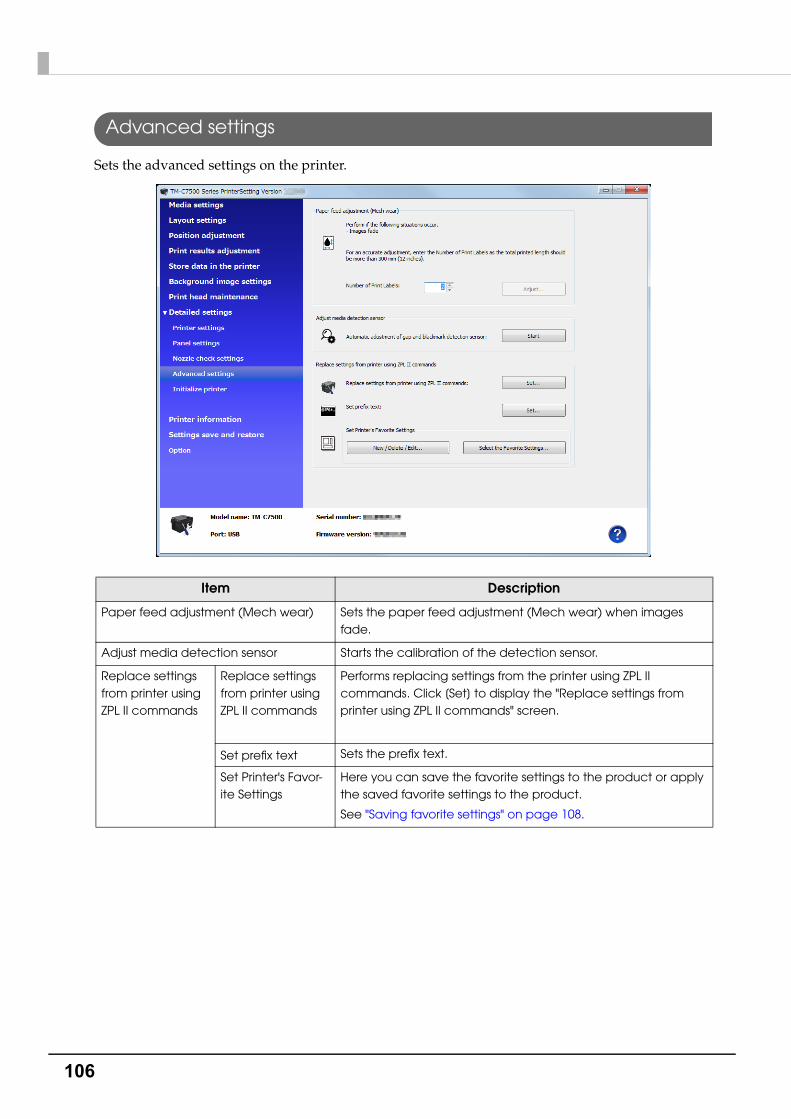
106
Advanced settings
Sets the advanced settings on the printer.
Item Description
Paper feed adjustment (Mech wear) Sets the paper feed adjustment (Mech wear) when images fade.
Adjust media detection sensor Starts the calibration of the detection sensor.
Replace settings from printer using ZPL II commands
Replace settings from printer using ZPL II commands
Performs replacing settings from the printer using ZPL II commands. Click [Set] to display the "Replace settings from printer using ZPL II commands" screen.
Set prefix text Sets the prefix text.
Set Printer's Favor-ite Settings
Here you can save the favorite settings to the product or apply the saved favorite settings to the product.
See "Saving favorite settings" on page 108.

107
Chapter 3 Handling
3
Replace settings from printer using ZPL II commands
1 Click [Set] for [Replace settings from printer using ZPL II commands] to dis-play the "Replace settings from printer using ZPL II commands" window.
2 Select the same resolution as the printer using ZPL II commands, and then set [Use in Monochrome Print Mode] to ON. Click [Apply settings].
3 The confirmation window is displayed. Click [Yes] to reflect the settings.
4 The result is displayed. Click [OK].
When you click [Default settings], the entered value returns to the printer's default value. When
you click [Apply settings], the settings return to the printer's default settings.
Adjust the font width while actually printing.
Regarding printer replacement, see "Changing Printer Settings and Replacing the Printer"
on page 175.
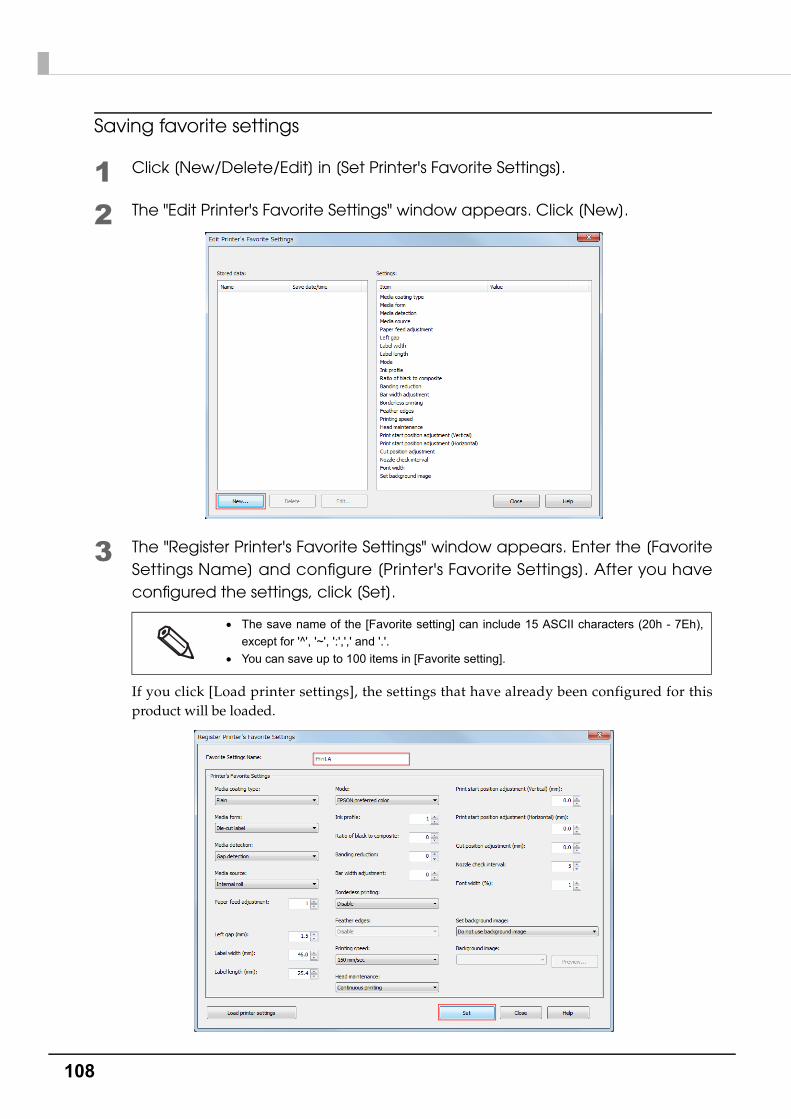
108
Saving favorite settings
1 Click [New/Delete/Edit] in [Set Printer's Favorite Settings].
2 The "Edit Printer's Favorite Settings" window appears. Click [New].
3 The "Register Printer's Favorite Settings" window appears. Enter the [Favorite Settings Name] and configure [Printer's Favorite Settings]. After you have configured the settings, click [Set].
If you click [Load printer settings], the settings that have already been configured for this product will be loaded.
The save name of the [Favorite setting] can include 15 ASCII characters (20h - 7Eh),
except for '^', '~', ':',',' and '.'.
You can save up to 100 items in [Favorite setting].
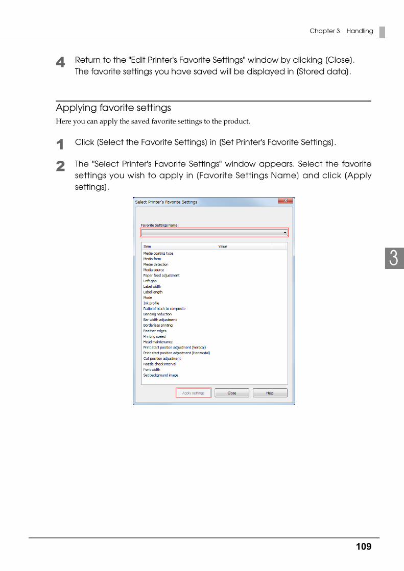
109
Chapter 3 Handling
3
4 Return to the "Edit Printer's Favorite Settings" window by clicking [Close]. The favorite settings you have saved will be displayed in [Stored data].
Applying favorite settingsHere you can apply the saved favorite settings to the product.
1 Click [Select the Favorite Settings] in [Set Printer's Favorite Settings].
2 The "Select Printer's Favorite Settings" window appears. Select the favorite settings you wish to apply in [Favorite Settings Name] and click [Apply settings].
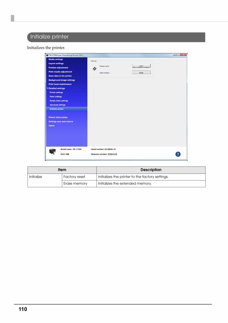
110
Initialize printer
Initializes the printer.
Item Description
Initialize Factory reset Initializes the printer to the factory settings.
Erase memory Initializes the extended memory.

111
Chapter 3 Handling
3
Printer information
Displays the printer information.
Item Description
Printer information Printer settings list When [View...] is clicked, the settings information of the current printer is displayed. Refer to "Printer settings list" on page 112.
Maintenance counters The maintenance counters can be checked.

112
Printer settings listWhen [View...] of the printer settings list is clicked, the "Printer settings list" screen is displayed. Click [Output to file...] to save the current settings to a text file.
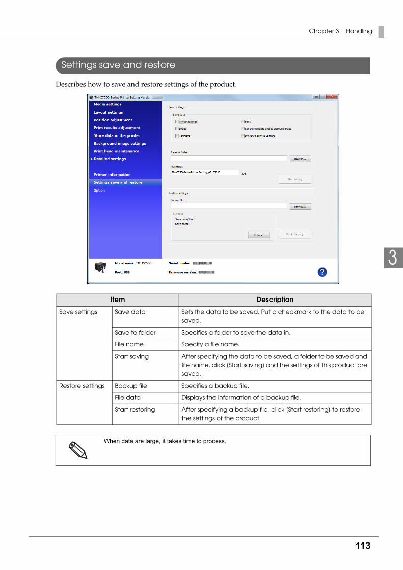
113
Chapter 3 Handling
3
Settings save and restore
Describes how to save and restore settings of the product.
Item Description
Save settings Save data Sets the data to be saved. Put a checkmark to the data to be saved.
Save to folder Specifies a folder to save the data in.
File name Specify a file name.
Start saving After specifying the data to be saved, a folder to be saved and file name, click [Start saving] and the settings of this product are saved.
Restore settings Backup file Specifies a backup file.
File data Displays the information of a backup file.
Start restoring After specifying a backup file, click [Start restoring] to restore the settings of the product.
When data are large, it takes time to process.

114
Option
Set the unit used in PrinterSetting and settings at the start.
Item Description
Display settings Units Sets the units.
Startup Settings Display a welcome screen at startup.
Initializes the expanded memory.
Unit settings are only for PrinterSetting. They are not reflected on the operation panel or the printer
driver.

115
Chapter 3 Handling
3
Setting the Printer Driver
Favorite Setting
[Favorite Setting] is the function to administer print setting of the printer driver into one.
The setting from [General] and [Options] tab such as Media Coating Type, Media Layout (including User Defined Media) are included.
[Favorite setting] of the printer driver is different from [Favorite setting] of the product. The two
functions are not compatible. It cannot be combined with [Favorite setting] of the product.
[General] tab
[Options] tab
Favorite Setting

116
Features• When printing from application, the print setting registered on [Favorite Setting] can be selected
as default setting.It is recommended to register the setting in favorite setting after executing print setting by clicking [Save as Favorite Setting].
• A number of setting can be registered on [Favorite Setting]. For example, if the print setting is registered on [Favorite Setting] for each document, the print setting can be completed by changing [Favorite Setting] when the document is changed. This prevents an error of setting change when changing the paper. (It is necessary to change Media position detection of the printer when the document is changed.)

117
Chapter 3 Handling
3
Registering print setting on [Favorite Setting]
1 Set the printer driver depending on paper to print.Set settings on [General] and [Options] tab. Select Media Layout in the [General] when using User Defined Media.
2 Click [Save As Favorite Setting] to display [Save/Delete Favorite Setting].The current setting will be displayed on the List of the right side.
3 Enter print name.
4 Click [Save].The print setting will be registered in [Favorite Setting], the [Save/Delete Favorite Setting] screen will close, and you will return to the original screen.
[Favorite Setting] includes the following setting.
• Default Settings: The default setting when installing the printer driver.
• Current Settings: The contents set on [General] and [Option] tab. These contents are displayed in the current settings on [Current Settings] and [Save/Delete Favorite Setting] window.
• User Defined Setting: The print setting defined by the user.
User Defined Media
(1) (2)
(3)
Current Settings
(4)Registered to Favorite Setting
118
User Defined Information
The user definition includes the following.
• User Defined Media
• Registering barcode font
• Replacing font on .NET environment
The user definition is set on each client computer. When a number of printer drivers are installed in one computer, these are used mutually.
Exporting/ Importing Printer Driver Settings
You can export the printing references, favorite setting, user-defined information (media layout, barcode) and printer driver operation settings into a BSF file (extension of ".BSF"). You can also import the settings from a BSF file to set up the printer driver.
Export SettingsFollow the steps below to export the settings.
1 Check that the print setting has been registered in [Favorite Setting]. If multi-ple print settings are registered, the print setting located first on the Favorite Setting will be reflected when importing the settings.
[Favorite setting] of the printer driver is different from [Favorite setting] of the product. [Favorite
setting] of the product cannot be included in the settings file of the printer driver.
To edit the order of the Favorite Setting, open the [Save/Delete Favorite Setting] screen,
select a print setting registered in the List, and click [Up] or [Down].
If nothing is registered in your favorites, the printer driver's initial settings are reflected.
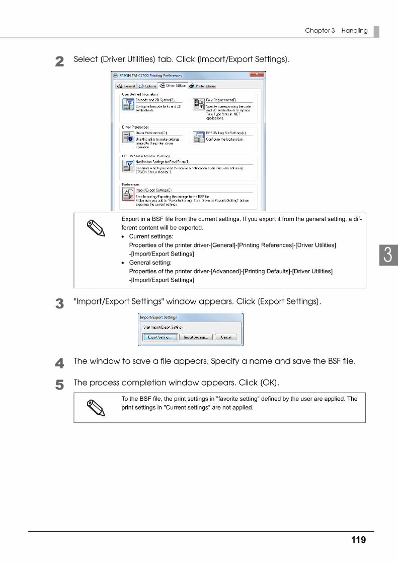
119
Chapter 3 Handling
3
2 Select [Driver Utilities] tab. Click [Import/Export Settings].
3 "Import/Export Settings" window appears. Click [Export Settings].
4 The window to save a file appears. Specify a name and save the BSF file.
5 The process completion window appears. Click [OK].
Export in a BSF file from the current settings. If you export it from the general setting, a dif-
ferent content will be exported.
Current settings:Properties of the printer driver-[General]-[Printing References]-[Driver Utilities]-[Import/Export Settings]
General setting:Properties of the printer driver-[Advanced]-[Printing Defaults]-[Driver Utilities]-[Import/Export Settings]
To the BSF file, the print settings in "favorite setting" defined by the user are applied. The
print settings in "Current settings" are not applied.
120
Import Settings
Follow the steps below to import the settings.
1 Select [Driver Utilities] tab. Click [Import/Export Settings].
2 "Import/Export Settings" window appears. Click [Import Settings].
3 The confirmation window appears. Click [OK].
4 The window to open a file appears. Select the file to be imported.
5 The process completion window appears. Click [OK].
When the settings are imported from a BSF file, the printer driver settings are overwritten. There-
fore, to retain the existing settings for the items listed below, create a BSF including the existing
settings.
Favorite List
User Defined Media List
Barcode Font List
Barcode Font Replacement List
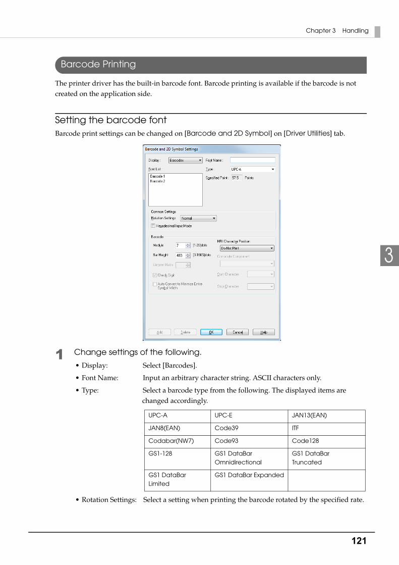
121
Chapter 3 Handling
3
Barcode Printing
The printer driver has the built-in barcode font. Barcode printing is available if the barcode is not created on the application side.
Setting the barcode fontBarcode print settings can be changed on [Barcode and 2D Symbol] on [Driver Utilities] tab.
1 Change settings of the following.
• Display: Select [Barcodes].
• Font Name: Input an arbitrary character string. ASCII characters only.
• Type: Select a barcode type from the following. The displayed items are changed accordingly.
• Rotation Settings: Select a setting when printing the barcode rotated by the specified rate.
UPC-A UPC-E JAN13(EAN)
JAN8(EAN) Code39 ITF
Codabar(NW7) Code93 Code128
GS1-128 GS1 DataBar Omnidirectional
GS1 DataBar Truncated
GS1 DataBar Limited
GS1 DataBar Expanded
122
• Hexadecimal Input Mode:Turn on the check box when the data for barcode is specified on Hexadecimal Input Mode.
• Module: Sets the thin element width in dots.(For details, see "Recommended value of the module" on page 123.)
• Bar Height: Sets the element height with dots. Specified dots indicate the actual print size.
• HRI Character Position:Select the position of the HRI characters. Select [Do Not Print] when not printing.
• Composite Component:Select the composite component.
• Element Ratio: Sets the thick element width by the ratio to the thin element width.The recommended minimum element ratio is 2.5.
• Check Digit: Values or marks appended to prevent sequential number errors or fabrication.
• Auto Convert to Minimize Entire Symbol Width::Selectable when CODE128 is specified. This function minimizes the number of symbol characters required to express the given data string.
• Start Character: Sets a start character.
• End Character: Sets an end character.
2 Click [Add].The selected barcode font is saved and the font name is added to the font list.
The printing position is limited for some types.
The barcode font can be registered up to 30.
The barcode font setting can be overwritten by clicking [Save] after selecting the font
name from the font list and changing the setting.
The barcode font setting can be deleted by clicking [Delete] after selecting the font name
from the font list.

123
Chapter 3 Handling
3
Recommended value of the moduleThe printing direction of the barcode is as follows. In addition, the recommended value of the module is different depending on the media type, barcode type and printing direction.
• Plain label
Barcode typePrinting
direction
Minimum Module [by 600 dpi]
ANSI Grade C or higher ANSI Grade B or higher
Code39Fence 5 7
Ladder 6 8
Codabar(NW7)Fence 5 6
Ladder 6 8
Code93Fence 5 7
Ladder 6 8
Code128
GS1-128
Fence 5 6
Ladder 6 7
ITFFence 6 8
Ladder 6 7
GS1 DataBar Omnidirectional
GS1 DataBar Truncated
Fence 6 6
GS1 DataBar Limited
GS1 DataBar ExpandedLadder 6 8
UPC-A
UPC-EFence 7 7
JAN13(EAN)
JAN8(EAN)Ladder 7 7

124
• Synthetic label
The recognition rate for the barcode varies depending on the media type, barcode
reader's performance and so on. The barcode rank may decline due to missing dots or
curving on the ink drops, making the barcode unreadable by the barcode reader. Thus,
we recommend that you try printing HRI characters and so on.
Ink may penetrate the paper due to its characteristics, and bars of printed barcodes
tend to become thicker. This tendency is more prominent with some papers. To
maintain the barcode recognition rate, use methods such as reducing the data in a bar
by 2 pixels and increasing the blank space by 2 pixels (Bar width adjustment).
Barcode typePrinting
direction
Minimum Module [by 600 dpi]
ANSI Grade C or higher ANSI Grade B or higher
Code39Fence 5 6
Ladder 5 6
Codabar(NW7)Fence 5 6
Ladder 5 6
Code93Fence 5 6
Ladder 5 6
Code128
GS1-128
Fence 5 6
Ladder 5 6
ITFFence 6 6
Ladder 6 6
GS1 DataBar Omnidirectional
GS1 DataBar Truncated
Fence 6 6
GS1 DataBar Limited
GS1 DataBar ExpandedLadder 6 6
UPC-A
UPC-EFence 7 7
JAN13(EAN)
JAN8(EAN)Ladder 7 7
The recognition rate for the barcode varies depending on the media type, barcode
reader's performance and so on. The barcode rank may decline due to missing dots or
curving on the ink drops, making the barcode unreadable by the barcode reader. Thus,
we recommend that you try printing HRI characters and so on.
Ink may penetrate the paper due to its characteristics, and bars of printed barcodes tend
to become thicker. This tendency is more prominent with some papers. To maintain the
barcode recognition rate, use methods such as reducing the data in a bar by 2 pixels and
increasing the blank space by 2 pixels (Bar width adjustment).
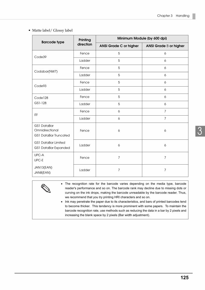
125
Chapter 3 Handling
3
• Matte label/ Glossy label
Barcode typePrinting
direction
Minimum Module [by 600 dpi]
ANSI Grade C or higher ANSI Grade B or higher
Code39Fence 5 6
Ladder 5 6
Codabar(NW7)Fence 5 6
Ladder 5 6
Code93Fence 5 6
Ladder 5 6
Code128
GS1-128
Fence 5 6
Ladder 5 6
ITFFence 6 7
Ladder 6 7
GS1 DataBar Omnidirectional
GS1 DataBar Truncated
Fence 6 6
GS1 DataBar Limited
GS1 DataBar ExpandedLadder 6 6
UPC-A
UPC-EFence 7 7
JAN13(EAN)
JAN8(EAN)Ladder 7 7
The recognition rate for the barcode varies depending on the media type, barcode
reader's performance and so on. The barcode rank may decline due to missing dots or
curving on the ink drops, making the barcode unreadable by the barcode reader. Thus,
we recommend that you try printing HRI characters and so on.
Ink may penetrate the paper due to its characteristics, and bars of printed barcodes tend
to become thicker. This tendency is more prominent with some papers. To maintain the
barcode recognition rate, use methods such as reducing the data in a bar by 2 pixels and
increasing the blank space by 2 pixels (Bar width adjustment).

126
Specifying the barcode dataSpecify the barcode data by referring to the following descriptions.
About the composite symbol:
The switch between CC-A to CC-B can be automatically performed, but the customer needs to select explicitly for CC-C.(In case of GS1-128, the type of composite component can be selected from "None", "CC-A/CC-B" or "CC-C".)
About the HRI character:
When the total width of the HRI character is larger than that of the barcode, the HRI character width is set as the barcode width.
UPC-A
• Specify data in 11 digits. The check digit is automatically added.
UPC-E
• Specify data in 10 digits. 5 digits are a manufacturer code and the rest 5 digits are an item code.
JAN13(EAN)
• Specify data in 12 digits. The check digit is automatically added.
JAN8(EAN)
• Specify data in 7 digits. The check digit is automatically added.
Code39
• When both or either one of start/stop code (‘*’) is not specified, it is automatically added.
ITF
• When data of odd digit number is specified, “0” is automatically added to the head.
Codabar(NW7)
• Do not include the start code and stop code into data. The start code and stop code specified in the printer driver screen are added.
Composite Component Type Encodable Digit Number
CC-A 1 ~ 56 digits
CC-B 1 ~ 338 digits
CC-C 1 ~ 2361 digits

127
Chapter 3 Handling
3
Code93
• A start code, 2 check digits, stop code is automatically added.
• A character () that indicates a start code is printed for the head of the HRI character.
• A character () that indicates a stop code is printed for the end of the HRI character.
• HRI characters of the control characters (00h ~ 1Fh, 7Fh) are printed combining ‘■’ and an alphabetical character.
Code128
• Only when the automatic conversion is OFF, the start code is added on 2 digits at the front. When "Auto Convert to Minimize Entire Symbol Width" is enabled, a code selection character is selected automatically so that the entire width of the symbol becomes at minimum. Therefore, it is not necessary to specify a code selection character from an application. While the code selection character CODE A is selected, if {A is specified to select CODE A, an error
occurs. While the code selection character CODE B is selected, if {B is specified to select CODE B, an error
occurs. While the code selection character CODE C is selected, if one of the following is specified, an error
occurs.
ControlCharacter HRI
Character
ControlCharacter HRI
Character
ControlCharacter HRI
CharacterASCII
Hexa-decimal
ASCIIHexa-
decimalASCII
Hexa-decimal
NULL 00 ■U VT 0B ■K SYN 16 ■V
COH 01 ■A FF 0C ■L ETB 17 ■W
STX 02 ■B CR 0D ■M CAN 18 ■X
ETX 03 ■C SO 0E ■N EM 19 ■Y
EOT 04 ■D SI 0F ■O SUB 1A ■Z
ENQ 05 ■E DLE 10 ■P ESC 1B ■A
ACK 06 ■F DC1 11 ■Q FS 1C ■B
BEL 07 ■G DC2 12 ■R GS 1D ■C
BS 08 ■H DC3 13 ■S RS 1E ■D
HT 09 ■I DC4 14 ■T US 1F ■E
LF 0A ■J NAK 15 ■U DEL 7F ■F
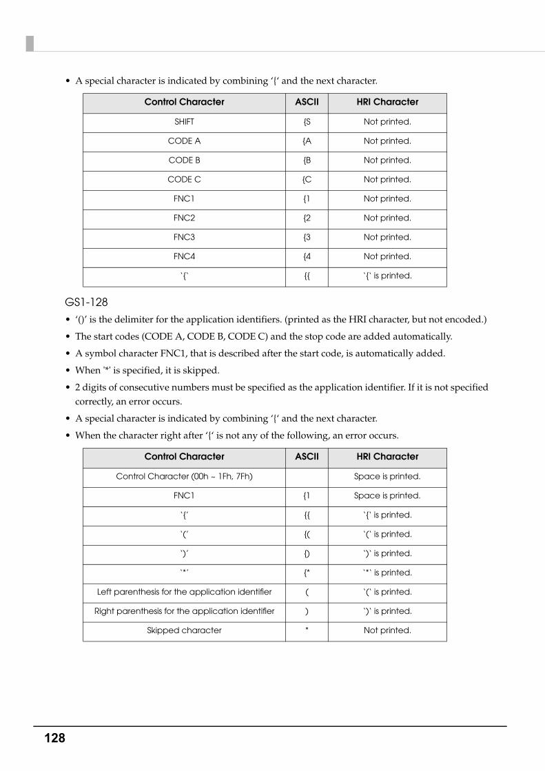
128
• A special character is indicated by combining ‘{‘ and the next character.
GS1-128
• ‘()’ is the delimiter for the application identifiers. (printed as the HRI character, but not encoded.)
• The start codes (CODE A, CODE B, CODE C) and the stop code are added automatically.
• A symbol character FNC1, that is described after the start code, is automatically added.
• When '*' is specified, it is skipped.
• 2 digits of consecutive numbers must be specified as the application identifier. If it is not specified correctly, an error occurs.
• A special character is indicated by combining ‘{‘ and the next character.
• When the character right after ‘{‘ is not any of the following, an error occurs.
Control Character ASCII HRI Character
SHIFT {S Not printed.
CODE A {A Not printed.
CODE B {B Not printed.
CODE C {C Not printed.
FNC1 {1 Not printed.
FNC2 {2 Not printed.
FNC3 {3 Not printed.
FNC4 {4 Not printed.
‘{‘ {{ ‘{‘ is printed.
Control Character ASCII HRI Character
Control Character (00h ~ 1Fh, 7Fh) Space is printed.
FNC1 {1 Space is printed.
‘{’ {{ ‘{‘ is printed.
‘(’ {( ‘(‘ is printed.
‘)’ {) ‘)‘ is printed.
‘*’ {* ‘*‘ is printed.
Left parenthesis for the application identifier ( ‘(‘ is printed.
Right parenthesis for the application identifier ) ‘)‘ is printed.
Skipped character * Not printed.
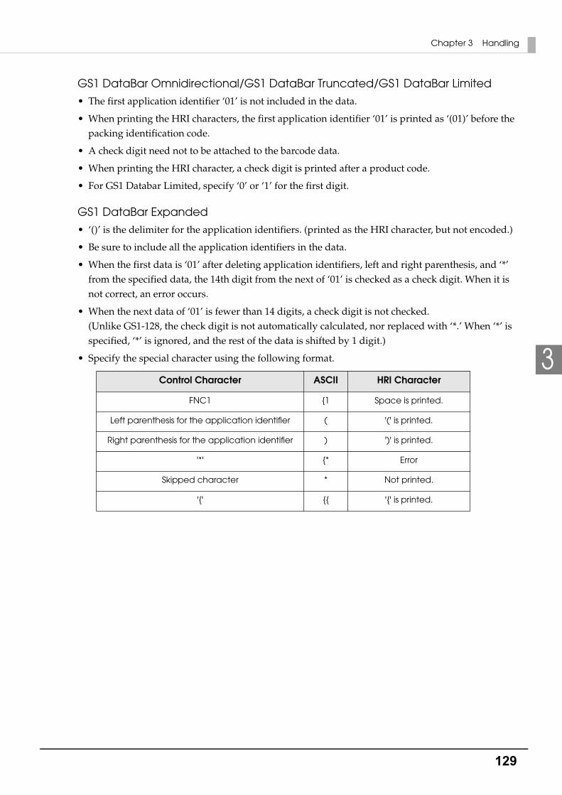
129
Chapter 3 Handling
3
GS1 DataBar Omnidirectional/GS1 DataBar Truncated/GS1 DataBar Limited
• The first application identifier ‘01’ is not included in the data.
• When printing the HRI characters, the first application identifier ‘01’ is printed as ‘(01)’ before the packing identification code.
• A check digit need not to be attached to the barcode data.
• When printing the HRI character, a check digit is printed after a product code.
• For GS1 Databar Limited, specify ‘0’ or ‘1’ for the first digit.
GS1 DataBar Expanded
• ‘()’ is the delimiter for the application identifiers. (printed as the HRI character, but not encoded.)
• Be sure to include all the application identifiers in the data.
• When the first data is ‘01’ after deleting application identifiers, left and right parenthesis, and ‘*’ from the specified data, the 14th digit from the next of ‘01’ is checked as a check digit. When it is not correct, an error occurs.
• When the next data of ‘01’ is fewer than 14 digits, a check digit is not checked. (Unlike GS1-128, the check digit is not automatically calculated, nor replaced with ‘*.’ When ‘*’ is specified, ‘*’ is ignored, and the rest of the data is shifted by 1 digit.)
• Specify the special character using the following format.
Control Character ASCII HRI Character
FNC1 {1 Space is printed.
Left parenthesis for the application identifier ( '(' is printed.
Right parenthesis for the application identifier ) ')' is printed.
'*' {* Error
Skipped character * Not printed.
'{' {{ '{' is printed.

130
Printing methodSpecify the selected barcode font, specified point and language to the printing data, and then print it.
The font size of the barcode can not be changed by [Specified Point] value. The barcode is not
printed when other values are selected.
Some applications, such as the .NET application, may not be able to display or select a
barcode font registered by the printer driver. In that case, if you use the font replacement
function to replace the True Type font with the barcode font, you can print barcodes. See
"Barcode and 2D Symbol Font Printing on .NET Environment" on page 138.

131
Chapter 3 Handling
3
2D symbol Printing
The printer driver has the built-in 2D symbol font. 2D symbol printing is available if the 2D symbol is not created on the application side.
Setting the 2D Symbol font2D symbol print settings can be changed on [Barcode and 2D Symbol Settings] on [Driver Utilities] tab.
1 Change settings of the following.
• Display: Select [2D Symbols].
• Font Name: Input an arbitrary character string. ASCII characters only.
• Type: Select a 2D symbol type. The displayed items are changed accordingly.
• Rotation Settings: Select a setting when printing the 2D symbol rotated by the specified rate.
• Hexadecimal Input Mode: Turn on the check box when the data for 2D symbol is specified on Hexadecimal Input Mode.
132
2 Make settings of the following items according to the selected [Type].
• PDF417 Module Width: Makes settings of the module width for PDF417.
"Recommended value of the module" on page 134 for the recommended value.
Module Height: Makes settings of the module height for PDF417 by the ratio to the mod-ule width. "Recommended value of the module" on page 134 for the rec-ommended value.
Column: Input the number of columns for PDF417. Step: Enter the number of steps for PDF417. Truncation Symbol: Turn on this check box when making a symbol without the stop code. Error Correction Level:
Select an error correction level for PDF417. The data can be read even if the part of the symbol is broken, and restoration ratio becomes higher for bigger numbers.
• MicroPDF417 Module Width: Makes settings of the module width for MicroPDF417.
"Recommended value of the module" on page 134 for the recommended value.
Module Height: Makes settings of the module height for MicroPDF417 by the ratio to the module width. "Recommended value of the module" on page 134 for the recommended value.
Column: Input the number of columns for MicroPDF417. Step: Enter the number of steps for MicroPDF417.
• QRCode
Model: Select a QRCode model. Module: Select the width of cell (module) for QRCode.
"Recommended value of the module" on page 134 for the recommended value.
Error Correction Level:Select an error correction level for QRCode. The data can be read if the part of the symbol is broken and restoration ratio becomes higher in the order of level L, M, Q, H.
Character Mode Specify a character string mode to encode to QRCode.
• MicroQRCode
Version: Specify the version for MicroQRCode. Module: Select the width of cell (module) for MicroQRCode.
"Recommended value of the module" on page 134 for the recommended value.
Error Correction Level:Select an error correction level for MicroQRCode. The data can be read if the part of the symbol is broken and restoration ratio becomes higher in the order of level L, M.
• MaxiCode Mode: Select a MaxiCode mode.
133
Chapter 3 Handling
3
• GS1 DataBar Module: Sets the module width for GS1 DataBar.
"Recommended value of the module" on page 134 for the recommended value.
Number of Characters:Sets the maximum width for GS1 DataBar.Set when GS1 DataBar Expanded Stacked is selected for the 2D symbol.
• AztecCode Type: Select a mode for AztecCode. Cell Size: Select the width of cell (module) for AztecCode.
"Recommended value of the module" on page 134 for the recommended value.
Number of Layers: Select the number of layers for AztecCode.[Minimize]: Optimize the minimum number of layers automatically.[Specify the Size]: Change the number of layers specified by the value in the input box.
Error Correction Area:Specify the error correction area of AztecCode using of either the follow-ing. The data can be read even if the part of the symbol is broken, and res-toration ratio becomes higher for bigger numbers.[Auto]:Default value is 23%+3 code words.[Specify a Percentage]: Specify the error correction area with a percentage value in the input box.
• DataMatrix Symbol Shape: Set when "Rectangle" is selected for the sample shape of DataMatrix. Error Correction Level:
Select an error correction level for DataMatrix. Cell Size: Select the width of cell (module) for DataMatrix.
"Recommended value of the module" on page 134 for the recommended value.
Number of Vertical Cells:Specify the number of cells for DataMatrix in the vertical direction.Set when "Rectangle" is selected for the sample shape of DataMatrix.
Number of Horizontal Cells:Specify the number of cells for DataMatrix in the horizontal direction. Set when "Rectangle" is selected for the sample shape of DataMatrix.[Minimize]: Optimize the minimum number of cells automatically.[Specify the Size]: Change settings to the selected size.
3 Click [Add].The selected 2D symbol font is saved and the font name is added to the font list.
The 2D symbol font can be registered up to 30.
The 2D symbol font setting can be overwritten by clicking [Save] after selecting the font
name from the font list and changing the setting.
The 2D symbol font setting can be deleted by clicking [Delete] after selecting the font name
from the font list.

134
Recommended value of the moduleThe recommended value of the module is different depending on media type, two-dimensional symbols type and printing direction.
2D symbol of stack type
• Plain label
• Synthetic label
❏ Matte label/ Glossy label
2D symbol typeMinimum Module [by 600 dpi]
ANSI Grade C or higher ANSI Grade B or higher
PDF417 5 5
MicroPDF417 5 6
GS1 DataBar Stacked
GS1 DataBar Stacked Omnidirectional
GS1 DataBar Expanded Stacked
5 5
2D symbol typeMinimum Module [by 600 dpi]
ANSI Grade C or higher ANSI Grade B or higher
PDF417 5 5
MicroPDF417 5 5
GS1 DataBar Stacked
GS1 DataBar Stacked Omnidirectional
GS1 DataBar Expanded Stacked
5 5
2D symbol typeMinimum Module [by 600 dpi]
ANSI Grade C or higher ANSI Grade B or higher
PDF417 5 5
MicroPDF417 5 5
GS1 DataBar Stacked
GS1 DataBar Stacked Omnidirectional
GS1 DataBar Expanded Stacked
5 6

135
Chapter 3 Handling
3
2D symbol of matrix type
• Plain label
• Synthetic label
• Matte label/ Glossy label
2D symbol typeMinimum Module [by 600 dpi]
ANSI Grade C or higher ANSI Grade B or higher
QR Code 10 12
Micro QR Code 12 12
AztecCode 8 9
DataMatrix 8 10
Maxi Code 21 21
2D symbol typeMinimum Module [by 600 dpi]
ANSI Grade C or higher ANSI Grade B or higher
QR Code 10 11
Micro QR Code 12 12
AztecCode 8 9
DataMatrix 8 9
Maxi Code 21 21
2D symbol typeMinimum Module [by 600 dpi]
ANSI Grade C or higher ANSI Grade B or higher
QR Code 9 11
Micro QR Code 11 12
AztecCode 8 9
DataMatrix 7 9
Maxi Code 21 21

136
Specifying the 2D symbol dataSee the following description to specify the 2D symbol data.
PDF417/MicroPDF417
• Calculated automatically when the digit number and the line number are 0.
• To specify other number than 0, make sure the multiplication of the digit number and the line number is under 928.
QRCode
• It is changed automatically to the appropriate version.
Micro QRCode
• The size is automatically determined.
MaxiCode
• Specify the special character as the following format.
DataMatrix
• When data are '{', if the following does not apply to the data immediately after, an error occurs.
GS1 DataBar Stacked /GS1 DataBar Stacked Omnidirectional
• Do not specify the application identifier ‘01’ for the head of the data.
• A check digit need not to be attached to the data.
• When printing a 2D symbol with a composite symbol, delimit the data that specify a composite symbol and 2D symbol with "\|" or "|\". Specify the data in order of a composite symbol and 2D symbol.
Control Character Hexadecimal
SHIFT 0x7B, 0x53
CODE B 0x7B, 0x42
CODE C 0x7B, 0x43
FNC1 0x7B, 0x31
FNC2 0x7B, 0x32
FNC3 0x7B, 0x33
FNC4 0x7B, 0x34
Control Character ASCII
FNC1 {1
'{' {{
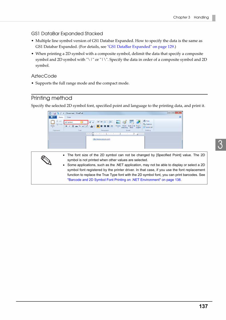
137
Chapter 3 Handling
3
GS1 DataBar Expanded Stacked
• Multiple line symbol version of GS1 Databar Expanded. How to specify the data is the same as GS1 Databar Expanded. (For details, see "GS1 DataBar Expanded" on page 129.)
• When printing a 2D symbol with a composite symbol, delimit the data that specify a composite symbol and 2D symbol with "\|" or "|\". Specify the data in order of a composite symbol and 2D symbol.
AztecCode
• Supports the full range mode and the compact mode.
Printing methodSpecify the selected 2D symbol font, specified point and language to the printing data, and print it.
The font size of the 2D symbol can not be changed by [Specified Point] value. The 2D
symbol is not printed when other values are selected.
Some applications, such as the .NET application, may not be able to display or select a 2D
symbol font registered by the printer driver. In that case, if you use the font replacement
function to replace the True Type font with the 2D symbol font, you can print barcodes. See
"Barcode and 2D Symbol Font Printing on .NET Environment" on page 138.
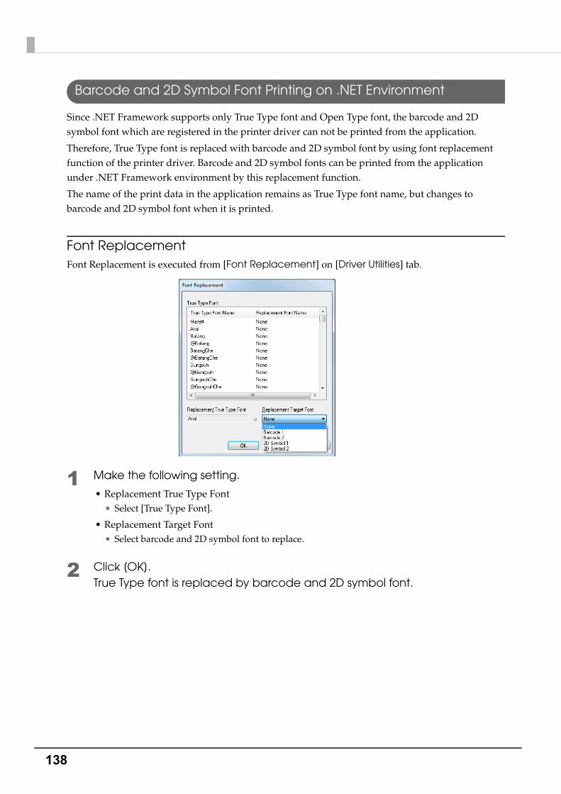
138
Barcode and 2D Symbol Font Printing on .NET Environment
Since .NET Framework supports only True Type font and Open Type font, the barcode and 2D symbol font which are registered in the printer driver can not be printed from the application.
Therefore, True Type font is replaced with barcode and 2D symbol font by using font replacement function of the printer driver. Barcode and 2D symbol fonts can be printed from the application under .NET Framework environment by this replacement function.
The name of the print data in the application remains as True Type font name, but changes to barcode and 2D symbol font when it is printed.
Font ReplacementFont Replacement is executed from [Font Replacement] on [Driver Utilities] tab.
1 Make the following setting.
• Replacement True Type Font Select [True Type Font].
• Replacement Target Font Select barcode and 2D symbol font to replace.
2 Click [OK].True Type font is replaced by barcode and 2D symbol font.
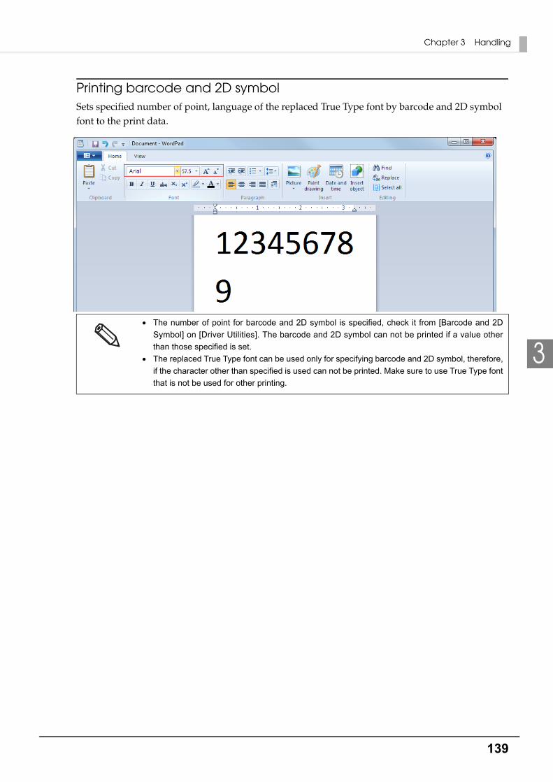
139
Chapter 3 Handling
3
Printing barcode and 2D symbolSets specified number of point, language of the replaced True Type font by barcode and 2D symbol font to the print data.
The number of point for barcode and 2D symbol is specified, check it from [Barcode and 2D
Symbol] on [Driver Utilities]. The barcode and 2D symbol can not be printed if a value other
than those specified is set.
The replaced True Type font can be used only for specifying barcode and 2D symbol, therefore,
if the character other than specified is used can not be printed. Make sure to use True Type font
that is not be used for other printing.
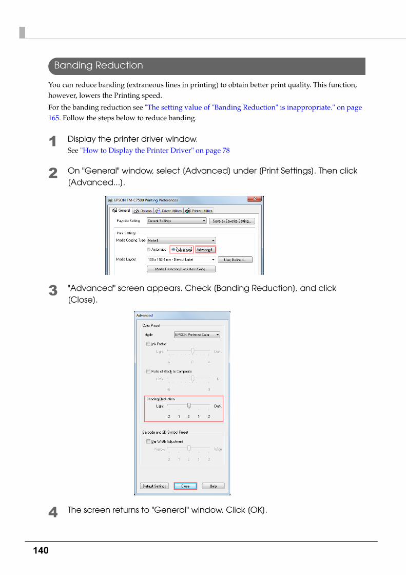
140
Banding Reduction
You can reduce banding (extraneous lines in printing) to obtain better print quality. This function, however, lowers the Printing speed.
For the banding reduction see "The setting value of "Banding Reduction" is inappropriate." on page 165. Follow the steps below to reduce banding.
1 Display the printer driver window.See "How to Display the Printer Driver" on page 78
2 On "General" window, select [Advanced] under [Print Settings]. Then click [Advanced...].
3 "Advanced" screen appears. Check [Banding Reduction], and click [Close].
4 The screen returns to "General" window. Click [OK].
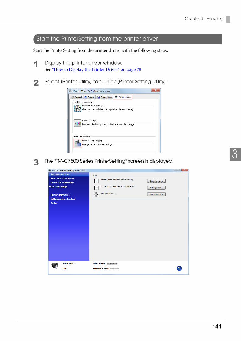
141
Chapter 3 Handling
3
Start the PrinterSetting from the printer driver.
Start the PrinterSetting from the printer driver with the following steps.
1 Display the printer driver window.See "How to Display the Printer Driver" on page 78
2 Select [Printer Utility] tab. Click [Printer Setting Utility].
3 The "TM-C7500 Series PrinterSetting" screen is displayed.
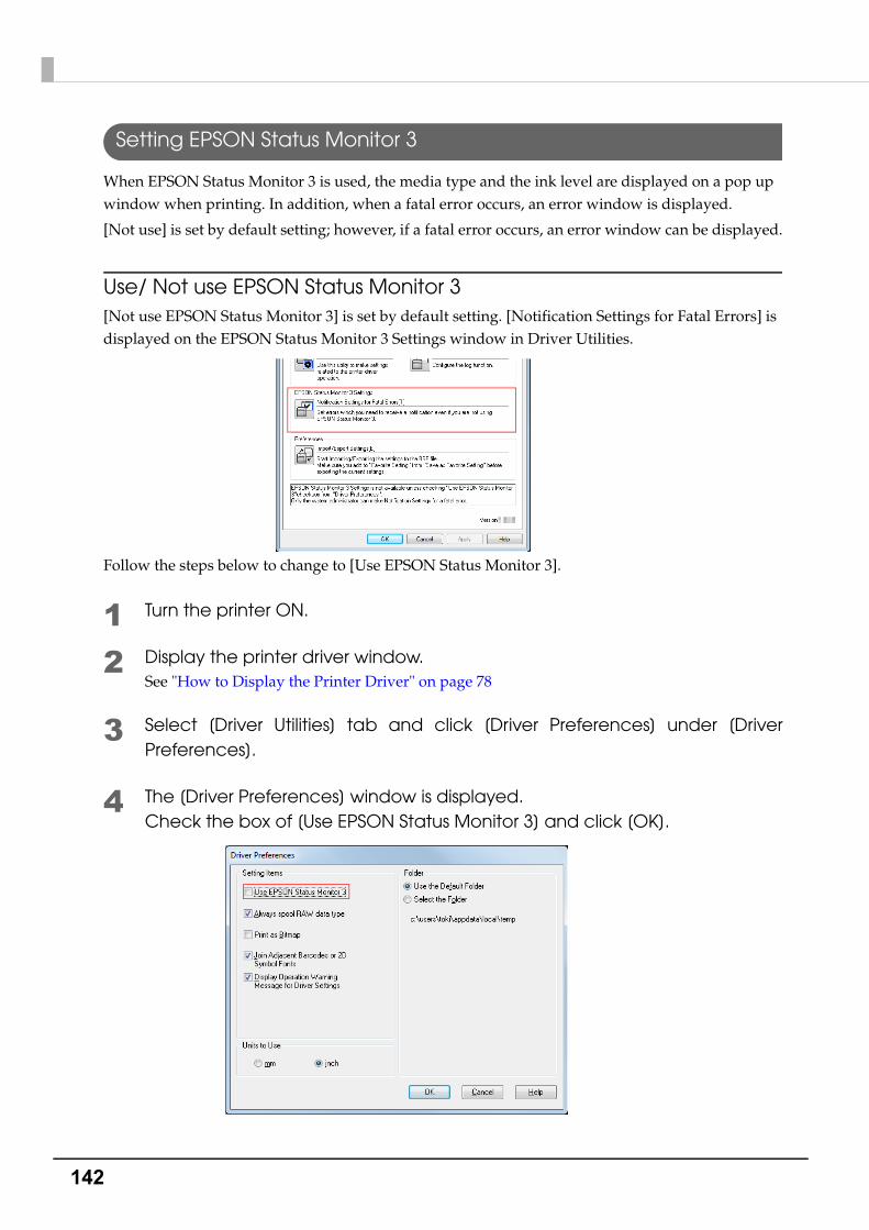
142
Setting EPSON Status Monitor 3
When EPSON Status Monitor 3 is used, the media type and the ink level are displayed on a pop up window when printing. In addition, when a fatal error occurs, an error window is displayed.
[Not use] is set by default setting; however, if a fatal error occurs, an error window can be displayed.
Use/ Not use EPSON Status Monitor 3[Not use EPSON Status Monitor 3] is set by default setting. [Notification Settings for Fatal Errors] is displayed on the EPSON Status Monitor 3 Settings window in Driver Utilities.
Follow the steps below to change to [Use EPSON Status Monitor 3].
1 Turn the printer ON.
2 Display the printer driver window.See "How to Display the Printer Driver" on page 78
3 Select [Driver Utilities] tab and click [Driver Preferences] under [Driver Preferences].
4 The [Driver Preferences] window is displayed.Check the box of [Use EPSON Status Monitor 3] and click [OK].

143
Chapter 3 Handling
3
5 [EPSON Status Monitor 3] and [Monitoring Preferences] are displayed in [EPSON Status Monitor 3 Settings] on the Driver Utilities window.
Use EPSON Status Monitor 3When [Use EPSON Status Monitor 3] is set, the following operations will be performed:
• When printing, a window automatically appears, allowing you to check the printer status and the ink level.
• Error information is displayed when an error occurs during printing.The EPSON Status Monitor 3 will not be activated if an error occurs when not printing.
• Clicking the icon for [EPSON Status Monitor 3] on the task tray allows you to display [EPSON Status Monitor 3] at any time.(See "Displaying the icon" on page 147 for how to display the icon.)
Display window for EPSON Status Monitor 3 Icon on task tray

144
• The following items can be set in [Monitoring preferences].Selecting error indications:(See "Error notification setting for [Not use EPSON Status Monitor 3]" on page 145)Displaying the [EPSON Status Monitor 3] icon on the task bar:(See "Displaying the icon" on page 147)

145
Chapter 3 Handling
3
Error notification setting for [Not use EPSON Status Monitor 3]Follow the steps below to set error notification for [Not use EPSON Status Monitor 3].
1 Turn the printer on.
2 Display the printer driver window.See "How to Display the Printer Driver" on page 78
3 Select [Driver Utilities] tab and click [Driver Preferences].When EPSON Status Monitor 3 is enabled, [Notification Settings for Fatal Errors] is not dis-played. (Disable "Use/ Not use EPSON Status Monitor 3" on page 142.)
4 The [Notification Settings for Fatal Errors] window is displayed. Select the items you want to display when an error occurs, and click [OK].
Ambient Temperature Error: When the printer temperature is high (Default: Screen Notification [On])
Service Required: When a no-print error or service-required error occurs (Default: Screen Notification [On])
Nozzle Clogged Warning: When the nozzle is clogged(Default: Screen Notification [On])
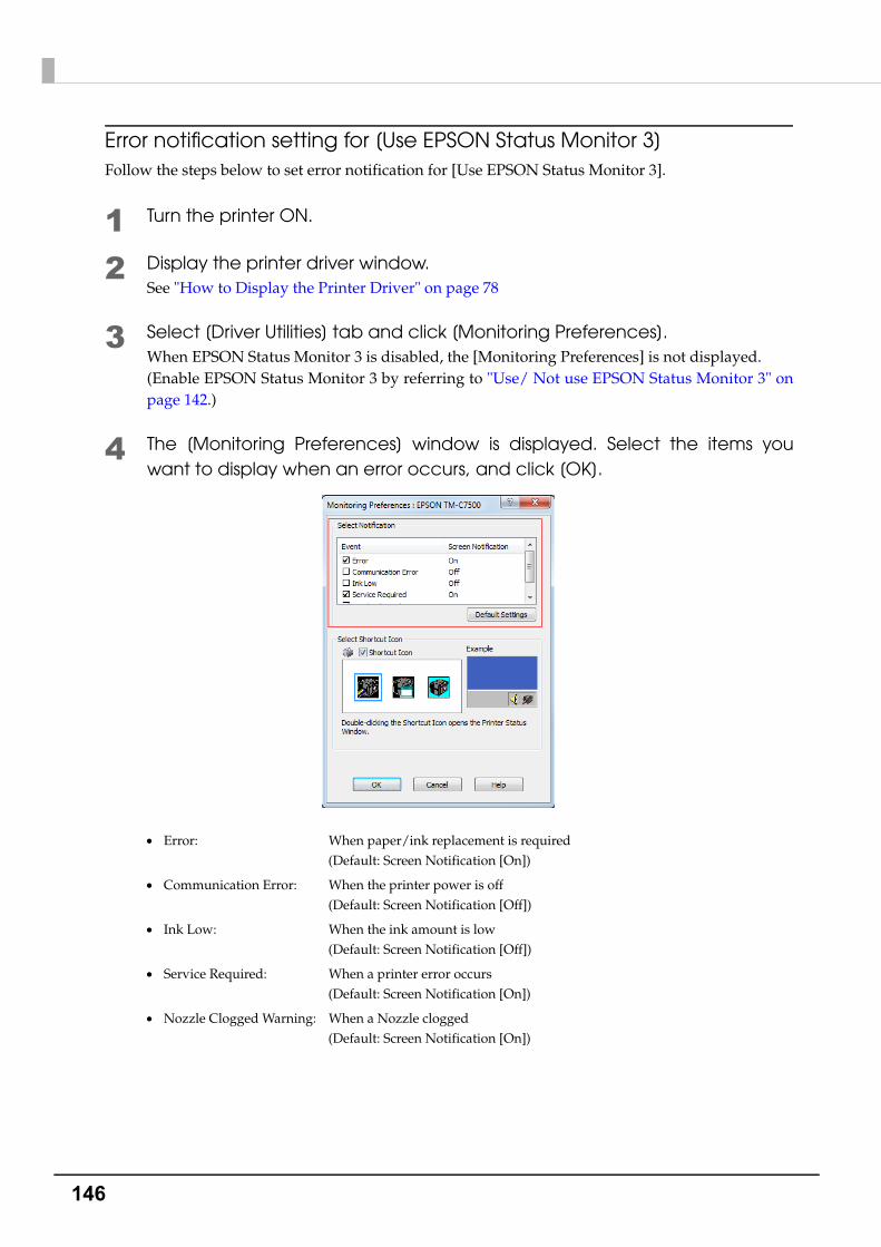
146
Error notification setting for [Use EPSON Status Monitor 3]Follow the steps below to set error notification for [Use EPSON Status Monitor 3].
1 Turn the printer ON.
2 Display the printer driver window.See "How to Display the Printer Driver" on page 78
3 Select [Driver Utilities] tab and click [Monitoring Preferences].When EPSON Status Monitor 3 is disabled, the [Monitoring Preferences] is not displayed.(Enable EPSON Status Monitor 3 by referring to "Use/ Not use EPSON Status Monitor 3" on page 142.)
4 The [Monitoring Preferences] window is displayed. Select the items you want to display when an error occurs, and click [OK].
Error: When paper/ink replacement is required(Default: Screen Notification [On])
Communication Error: When the printer power is off(Default: Screen Notification [Off])
Ink Low: When the ink amount is low(Default: Screen Notification [Off])
Service Required: When a printer error occurs(Default: Screen Notification [On])
Nozzle Clogged Warning: When a Nozzle clogged(Default: Screen Notification [On])

147
Chapter 3 Handling
3
Displaying the iconKeeps icon on the task tray so that user can check as needed. The icon is not displayed when default setting. Follow the steps below to display the icon.
1 Turn the printer ON.
2 Display the printer driver window.See "How to Display the Printer Driver" on page 78
3 Select [Driver Utilities] tab and click [Monitoring Preferences].
4 The [Monitoring Preferences] window is displayed. Check the box of [Shortcut Icon] and select the icon to display on the task bar. Click [OK].
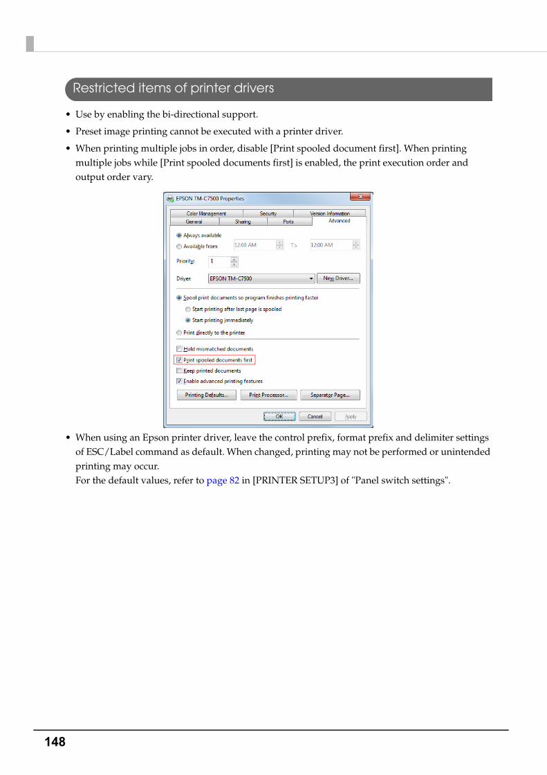
148
Restricted items of printer drivers
• Use by enabling the bi-directional support.
• Preset image printing cannot be executed with a printer driver.
• When printing multiple jobs in order, disable [Print spooled document first]. When printing multiple jobs while [Print spooled documents first] is enabled, the print execution order and output order vary.
• When using an Epson printer driver, leave the control prefix, format prefix and delimiter settings of ESC/Label command as default. When changed, printing may not be performed or unintended printing may occur.For the default values, refer to page 82 in [PRINTER SETUP3] of "Panel switch settings".

149
Chapter 3 Handling
3
USB Printer Class Device Replacement ServiceThis is a resident service on the computer. When the product is replaced for service or other reason, this detects the printer connection and automatically changes the output printer of the printer driver.This allows the printer to be replaced without changing settings in the application. (The printer is not replaced if a port is specified for the application output destination. The printer is only replaced if the printer driver is specified.)
There is no need to change the USB serial number of the product before replacement.
Uninstallation of USB Printer Class Device Replacement Service
USB Printer Class Device Replacement Service is not displayed in the software list in the control panel. For uninstallation, follow the steps below.
1 Close all applications running on the computer.
2 Select [Start] - [Control Panel] - [Uninstall a program] - [EPSON Printer Driver Utility]. Click [Uninstall/Change].
3 "EPSON Printer Utility Uninstall" screen appears. Select [Utility] tab.
4 Select [USB Replacement Service] and click [OK].Click [OK] to start uninstallation.
5 The completion window appears. Click [OK].

150
Restrictions in USB Printer Class Device Replacement Service
In using USB Printer Class Device Replacement Service on Windows 8 or Windows Server 2012, the following restrictions apply:
❏ After the printer is replaced, the green check mark indicating [default printer] in "Devices and Printers" window may be shown on the previous printer that was applied before replacement. Or the check mark may not appear. In these cases, the check mark indication can be corrected with the following steps:
• Return to the desktop screen and open "Devices and Printers" window again.
• Right-click the printer driver and select [Set as default printer].
• Log off the user account and restart the operating system.

151
Chapter 3 Handling
3
ReprintReprinting is carried out when an error other than a fatal error or maintenance error occurs during printing.
“During printing” means the time from paper loading up until the yellow head’s printing
operation ends.
This printer employs the 4-color line printing method, and so the reprinting will print one or
more (depending on the length of the labels used) unfinished pages in which printing by
some of the heads only is completed.
Reprinting is carried out in units of pages.
If an error that is the cause of reprint is cleared by canceling the job, printer reset, or power
on/off, the printer does not perform reprint.
Paper feed direction
Printer
Not included in reprinting
Included in reprinting
Included in reprinting
Yello
w h
ead
Mag
enta
hea
d
Cya
n he
ad
Bla
ck h
ead

152
Setting the Dip SwitchesFollow the steps below to change the Dip switch settings.
Setting Procedure
Follow the steps below to change the Dip switch settings.
1 Make sure the power supply for the product is turned off.
2 Remove the Dip switch cover mounting screw from the rear side of the product and open the Dip switch cover.
3 Set the DIP switches, using the tip of a tool, such as a tweezers.
4 Replace the DIP switch cover, and screw it in place.
Functions
CAUTION
Before you remove the DIP switch cover, turn the product off. Otherwise, a short-circuit may
cause the product to malfunction.
DIP switch settings are enabled only when the power is turned on. If the settings are changed
after that, the functions will not change.
SW ON OFF Initial setting
1Power button: Disabled
(Reset operation)
Power button: Enabled
(Power ON/OFF operation)OFF
2 Forbidden (Do not change setting) OFF
3 Reserved (Do not change setting) OFF
4 Reserved (Do not change setting) OFF
CAUTION
Do not change Dip switch 2 to 4.
An SDHC memory card is located below the dip switches. Do not remove it, replace it or do
anything else to it. This card is used for internal processing.
Dip Switch Cover
Dip Switch
Dip Switch Cover mounting screw

153
Chapter 3 Handling
3
Cleaning
Cleaning the autocutter
If adhesive from the label paper adheres to the autocutter, the autocutter may become blunt.
In this case, clean the autocutter with the following steps.
1 Turn the printer power off, and disconnect the AC cable from the wall out-let.
2 Open the roll paper cover and remove the paper.See "How to eject paper for paper replacement" on page 63
3 Remove the adhesive on the autocutter fixed blade of the roll paper cover side with a cotton swab. Slightly moisten the cotton swab with alcohol, if necessary.
How to Clean the CaseWhen cleaning the printer case, use absorbent cotton dampened with ethanol for disinfection or isopropyl alcohol if necessary.
WARNING
Do not touch the autocutter fixed blade directly with fingers during cleaning, or injury may
result.
154
Long-term Storage of the Product After Ink Charging
Storing the product
When not using the printer for an extended period of time after ink charging (after starting using), store it following the steps below.
1 Run a nozzle check print to check that no dot missing or other printing prob-lems have occurred. In case any printing problems have occurred, run manual head cleaning so that the printer recovers from the problem.See "Test printing" on page 76
2 After printing has completed, turn off the printer with the printer power but-ton.
3 Store the printer in a cool (0 to 25°C {32 to 77°F}) and dark place.
CAUTION
If dot missing has occurred, ink may clot inside the nozzle to cause nozzle clogging,
making it difficult for the printer to recover from the problem when the printer restarts.
Dot missing may occur especially after transporting the printer from the place where it is
used to the place where it is stored, due to vibration.
CAUTION
When powering off the product before storing for an extended period of time, make sure
to push the Power Button.When the Dip switch 1 is set to ON (Power button action is set to "Reset this product"),
set the Dip switch 1 to OFF.
See "Setting the Dip Switches" on page 152
CAUTION
Storage length is 6 months.
Store the product with the ink cartridge installed in the product.
155
Chapter 3 Handling
3
Restart the printer after long-term storage
When restarting the printer after a long-term storage, follow the steps below.
1 Check whether or not the ink cartridge storage period has been expired.
2 Turn on the product. The Nozzle Verification Technology runs to check for nozzle clogging, and then runs head cleaning automatically.
3 Run a nozzle check print and check whether dot missing or any other print-ing problems have occurred.
In the cases listed below, replace the ink cartridge.
See "Installing the Ink Cartridge" on page 43
2 years has passed since the ink cartridge was manufactured
6 months has passed since the ink cartridge was opened
CAUTION
Do not turn the product off or do not open Ink cartridge cover, Front cover, Rewinder
connection cover, Maintenance box cover, or Paper set cover during the head cleaning
operation.
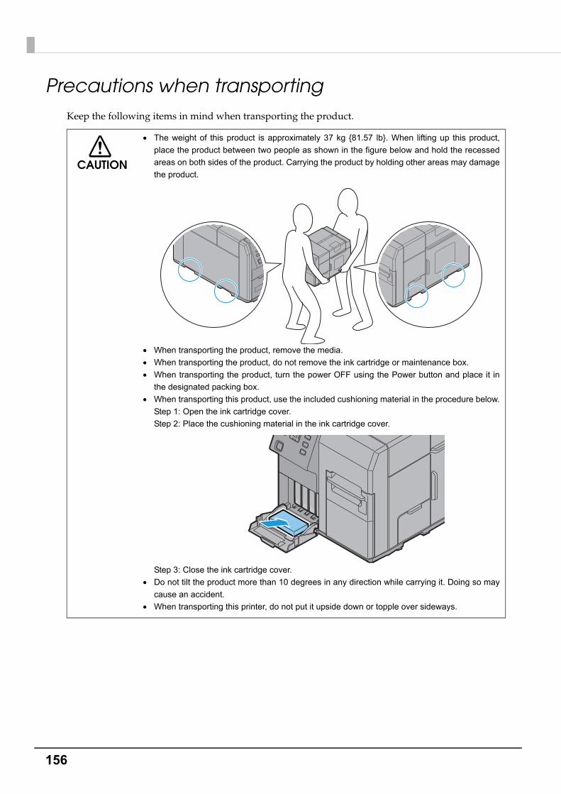
156
Precautions when transportingKeep the following items in mind when transporting the product.
CAUTION
The weight of this product is approximately 37 kg {81.57 lb}. When lifting up this product,
place the product between two people as shown in the figure below and hold the recessed
areas on both sides of the product. Carrying the product by holding other areas may damage
the product.
When transporting the product, remove the media.
When transporting the product, do not remove the ink cartridge or maintenance box.
When transporting the product, turn the power OFF using the Power button and place it in
the designated packing box.
When transporting this product, use the included cushioning material in the procedure below.
Step 1: Open the ink cartridge cover.
Step 2: Place the cushioning material in the ink cartridge cover.
Step 3: Close the ink cartridge cover.
Do not tilt the product more than 10 degrees in any direction while carrying it. Doing so may
cause an accident.
When transporting this printer, do not put it upside down or topple over sideways.

157
Chapter 3 Handling
3
Troubleshooting
Error Processing
LCD displayError
Description Recovery method
PAPER OUT
Paper out
There is no paper. When using roll paper:
1.Open the paper set cover.
2.Open the roll paper cover.
3. If there is any paper or a paper roll left, remove it.
4.Set a roll paper.
5.Run auto loading of the paper.
6.Close the paper set cover and roll paper cover.
When using fanfold paper:
1.Open the paper set cover.
2.Remove any remaining paper.
3.Set the new paper in place.
4.Run auto loading of the paper.
5.Close the paper set cover.
MEDIA DETECTION ERROR
Media detection error
The type of the paper set in the printer is different from the specified type set for “Media position detection settings”.
Set the type of paper specified for “Media position detection settings” or change the settings for “Media position detection settings” to that is suitable for the loaded paper.
The type of the paper set in the printer is different from the specified media type on the label printing application or the printer driver provided by the label printing application manufacturer.
Set the type of paper specified on "the label printing application" or "the printer driver provided by the label printing application manufacturer" to that is suitable for the loaded paper.
For instructions on how to change the settings, refer to "Media detector and paper path settings when using label printing applications" on page 215.
The type of the paper set in the printer is different from the specified media type on the favorite setting menu on the operation panel.
When using the [Favorite setting] function on the operation panel, select the media that is compatible with the media type configured in [Favorite setting] on the operation panel or select the settings that match the media in [Favorite setting] on the operation panel.
You cannot modify the settings in [Favorite setting] when this error occurs.
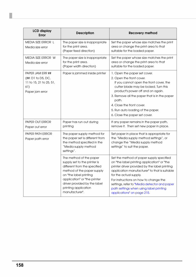
158
MEDIA SIZE ERROR L
Media size error
The paper size is inappropriate for the print area. (Paper feed direction)
Set the paper whose size matches the print area or change the print area to that suitable for the loaded paper.
MEDIA SIZE ERROR W
Media size error
The paper size is inappropriate for the print area. (Paper width direction)
Set the paper whose size matches the print area or change the print area to that suitable for the loaded paper.
PAPER JAM ERR ##
(##: D1 to D5, DC, 11 to 15, 21 to 25, 51, 61)
Paper jam error
Paper is jammed inside printer 1. Open the paper set cover.
2. Open the front cover.If you cannot open the front cover, the cutter blade may be locked. Turn this product's power off and on again.
3. Remove all the paper that is in the paper path.
4. Close the front cover.
5. Run auto loading of the paper.
6. Close the paper set cover.
PAPER OUT ERROR
Paper out error
Paper has run out during printing
If any paper remains in the paper path, remove it. Then set new paper in place.
PAPER PATH ERROR
Paper path error
The paper supply method for the paper set is different from the method specified in the “Media supply method settings”.
Set paper in place that is appropriate for the “Media supply method settings”, or change the “Media supply method settings” to suit the paper.
The method of the paper supply set to the printer is different from the specified method of the paper supply on "the label printing application" or "the printer driver provided by the label printing application manufacturer".
Set the method of paper supply specified on "the label printing application" or "the printer driver provided by the label printing application manufacturer" to that is suitable for the actual supply.
For instructions on how to change the settings, refer to "Media detector and paper path settings when using label printing applications" on page 215.
LCD displayError
Description Recovery method

159
Chapter 3 Handling
3
PAPER REMOVAL ERROR
Paper removal error
Paper is not set correctly in place, or paper has not been removed after ejection operation.
If no paper remains on the platen:
Set paper in place again.
See Appendix C for how to set the paper in place.
If paper remains on the platen:
1. Open the paper set cover.
2. Open the front cover.
3. Remove all the paper that is in the paper path.
4. Close the front cover.
5. Run auto loading of the paper.
When there is not much roll paper left, printing ended near the end of the roll paper.
Replace the roll paper.
ROLL COVER OPEN
Roll paper cover open
The roll paper cover is open. Close the roll paper cover.
PAPER COVER OPEN
Paper set cover open
The paper set cover is open Close the paper set cover.
FRONT COVER OPEN
Front cover open
The front cover is open Close the front cover.
INK COVER OPEN
Ink cartridge cover open
The ink cartridge cover is open. Close the ink cartridge cover.
NO INK CARTRIDGE
No ink cartridge
An ink cartridge is not loaded 1. Open the ink cartridge cover.
2. Load an ink cartridge with sufficient ink left.
3. Close the ink cartridge cover.
INK READ ERROR
Ink cartridge read error
The ink cartridge information could not be read.
1. Open the ink cartridge cover.
2. Remove the ink cartridge.
3. Load the ink cartridge again.
4. Close the ink cartridge cover.
5. If the error occurs again, replace the ink cartridge with a new one.
LCD displayError
Description Recovery method
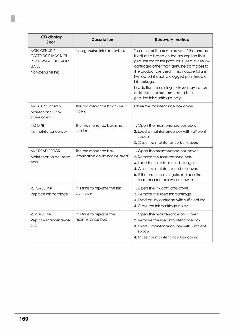
160
NON-GENUINE CARTRIDGE MAY NOT PERFORM AT OPTIMUM LEVEL
Non-genuine ink
Non-genuine ink is mounted. The color of the printer driver of the product is adjusted based on the assumption that genuine ink for the product is used. When ink cartridges other than genuine cartridges for the product are used, it may cause failure like low print quality, clogged print head or ink leakage.
In addition, remaining ink level may not be detected. It is recommended to use genuine ink cartridges only.
M/B COVER OPEN
Maintenance box cover open
The maintenance box cover is open.
Close the maintenance box cover.
NO M/B
No maintenance box
The maintenance box is not loaded.
1. Open the maintenance box cover.
2. Load a maintenance box with sufficient space.
3. Close the maintenance box cover.
M/B READ ERROR
Maintenance box read error
The maintenance box information could not be read.
1. Open the maintenance box cover.
2. Remove the maintenance box.
3. Load the maintenance box again.
4. Close the maintenance box cover.
5. If the error occurs again, replace the maintenance box with a new one.
REPLACE INK
Replace ink cartridge
It is time to replace the ink cartridge.
1. Open the ink cartridge cover.
2. Remove the used ink cartridge.
3. Load an ink cartridge with sufficient ink.
4. Close the ink cartridge cover.
REPLACE M/B
Replace maintenance box
It is time to replace the maintenance box.
1. Open the maintenance box cover.
2. Remove the used maintenance box.
3. Load a maintenance box with sufficient space.
4. Close the maintenance box cover.
LCD displayError
Description Recovery method
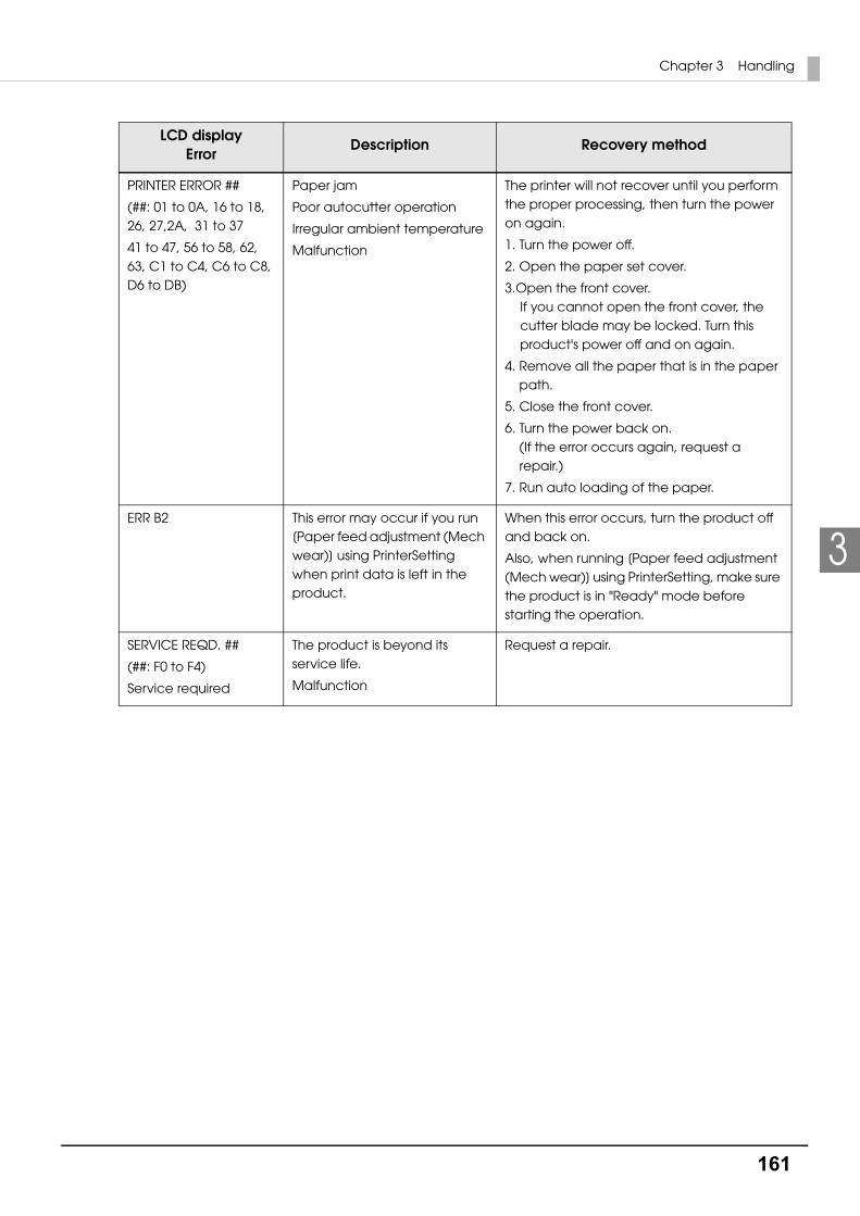
161
Chapter 3 Handling
3
PRINTER ERROR ##
(##: 01 to 0A, 16 to 18, 26, 27,2A, 31 to 37
41 to 47, 56 to 58, 62, 63, C1 to C4, C6 to C8, D6 to DB)
Paper jam
Poor autocutter operation
Irregular ambient temperature
Malfunction
The printer will not recover until you perform the proper processing, then turn the power on again.
1. Turn the power off.
2. Open the paper set cover.
3.Open the front cover.If you cannot open the front cover, the cutter blade may be locked. Turn this product's power off and on again.
4. Remove all the paper that is in the paper path.
5. Close the front cover.
6. Turn the power back on.(If the error occurs again, request a repair.)
7. Run auto loading of the paper.
ERR B2 This error may occur if you run [Paper feed adjustment (Mech wear)] using PrinterSetting when print data is left in the product.
When this error occurs, turn the product off and back on.
Also, when running [Paper feed adjustment (Mech wear)] using PrinterSetting, make sure the product is in "Ready" mode before starting the operation.
SERVICE REQD. ##
(##: F0 to F4)
Service required
The product is beyond its service life.
Malfunction
Request a repair.
LCD displayError
Description Recovery method

162
Warning Processing
LCD displayWarning type
Description Recovery method
INK LOW
Ink cartridge low
Ink is running low. Because it is almost time to replace the ink cartridge, prepare an ink cartridge for replacement. When the status changes to “Replace ink cartridge”, replace the ink cartridge.
M/B NEAR FULL
Maintenance box near full
The maintenance box is almost full.
Because it is almost time to replace the maintenance box, prepare a maintenance box for replacement. When the status changes to “Replace maintenance box”, replace the maintenance box.
NOZZLE CLOGGED
Print head nozzle clogged
Nozzle is clogged. Check the printing result and perform head cleaning. Execute manual head cleaning from [Cleaning] on the unit panel.
If the dot dropouts is not resolved by executing a manual head cleaning three or more times, execute INK RECHARGE on the operation panel.
For details, refer to "INK RECHARGE" on page 85
Check the printing result, and if the nozzle clog cannot be permitted, perform repairs.
CUT UNAVAILABLE
In cutter unavailable state
Autocutting is being performed 2 or more times with the paper in the same position.
Execute paper feed or printing operation.
To prevent occurrence of paper scraps, do not execute auto cutting two or more times without feeding the paper.
SERVICE MODE
In service mode
The product is in the mode for performing repairs and inspections.
-
SERVICE SOON ##
##: F0, F1
Service due soon
The product is near the end of its service life.
Because the internal parts of the printer are near the end of their service life, prepare to replace the printer, or prepare a printer for replacement. When the status changes to “Service required”, the printer will not recover until the necessary repairs are performed and the necessary area of the nonvolatile memory is overwritten.
PRINTING-NOZZLE CHECK DISABLED
Nozzle Verification Technology is disable
Nozzle Verification Technology is disable, or ambient temperature exceeds the operating range
Go to the setting items on the panel and set Nozzle Verification Technology to “Enable”.
Or, adjust the room (ambient) temperature to within the range from 5 to 35 °C {41 to 95°F}.

163
Chapter 3 Handling
3
Printer Driver
State Cause Recovery method
Status cannot be obtained with the status monitor.
"Enable the bi-direction support" in the "Port" setting of the driver properties is disabled.
When using an printer driver, enable the "Enable the bi-direction support" in the "Port" setting of the properties.
When using a ZPL II compatible printer driver with this product, printing may not be performed.
Check whether printing is possible by using the latest version of the ZPL II compatible printer
driver.

164
Poor print quality
State Cause Recovery method
Uneven printed colors
"Dot dropouts" are occurring.
From the [NOZZLE CHECK] on the unit panel, or from the [Printer Utilities] in the printer driver or PrinterSetting, use the [Manual Head Cleaning] and [Nozzle Check] to check for nozzle clogging. If the nozzle is clogged, execute a manual head cleaning from [CLEANING] on the unit panel.
If the dot dropouts is not resolved by executing a manual head cleaning three or more times, execute INK RECHARGE on the operation panel.
For details, refer to "INK RECHARGE" on page 85
Also, if the "Nozzle Verification Technology" in "Nozzle check settings" is disabled, change to enabled (default).
For details, refer to "Nozzle Verification Technology" on page 22
The "Media Coating Type" setting is different from the media that is actually used.
The "Media Coating Type" setting of the printer driver may be different from the media used.
Check the "Media Coating Type" setting of the printer driver and the media used.
For details, refer to "Paper settings" on page 69
"Paper feeding adjustment" is necessary.
Depending on the media, uneven printed colors may occur due to changes in the paper feed amount.
When position slipping of CMYK inks occurs as shown below, push the "General" tab of the printer driver to set an appropriate value in "Paper Feed Adjustment".
Also, start the PrinterSetting. Start the PrinterSetting from the printer driver. Select [Printer Utility] tab. Click [Printer Setting Utility] icon. Select "Detailed settings" and "Advanced settings" and execute "Paper feed adjustment (Mech wear)".
For details, refer to "Advanced settings" on page 106
When posit ive adjust-ment is necessary
When negative adjust-ment is necessary

165
Chapter 3 Handling
3
Uneven printed colors
The setting value of "Banding Reduction" is inappropriate.
When using the printer driver, color lines generated in the overlapping print head parts can be corrected as shown below by selecting "Banding Reduction" so that uneven printed colors may not stand out.
Select "Advanced" in "Print Settings" of the "General" tab, click the "Advanced..." and change the dark and light setting with "Banding Reduction".
(When light color lines are generated as shown in the left figure, move to the plus (+) direction to adjust. Also, when dark color lines are generated as shown in the right figure, move to the (-) direction to adjust.)
For details, refer to "Banding Reduction" on page 140
Also, if the "Nozzle Verification Technology" in "Nozzle check settings" is disabled, change to enabled (default).
Roll paper is not set properly.
For the roll paper, open the roll paper cover and reset the media correctly.
For details, refer to "Setting the Roll Paper" on page 54
Fanfold paper is not set properly.
For the fanfold paper, leave it 15 mm or more from the rear side of the printer and place the paper straight.
For details, refer to "Setting the Fanfold Paper" on page 62
Printed colors do not look right.
A head cleaning is necessary.
When the printer is moved after initial charging, there may be cases that specified colors are not printed out right ("Color mixing") due to vibration or shock.
Execute a manual head cleaning and check that the color mixing no longer occurs.
State Cause Recovery method
Example of light color irregularities
Example of dark color irregularities
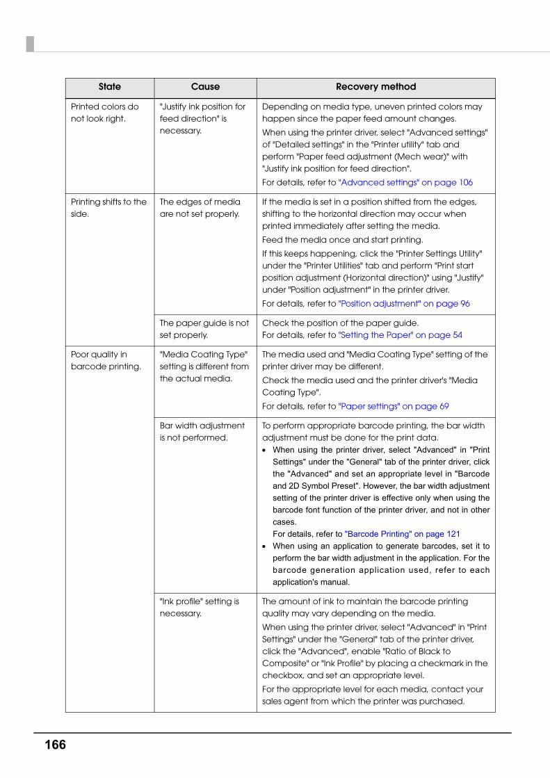
166
Printed colors do not look right.
"Justify ink position for feed direction" is necessary.
Depending on media type, uneven printed colors may happen since the paper feed amount changes.
When using the printer driver, select "Advanced settings" of "Detailed settings" in the "Printer utility" tab and perform "Paper feed adjustment (Mech wear)" with "Justify ink position for feed direction".
For details, refer to "Advanced settings" on page 106
Printing shifts to the side.
The edges of media are not set properly.
If the media is set in a position shifted from the edges, shifting to the horizontal direction may occur when printed immediately after setting the media.
Feed the media once and start printing.
If this keeps happening, click the "Printer Settings Utility" under the "Printer Utilities" tab and perform "Print start position adjustment (Horizontal direction)" using "Justify" under "Position adjustment" in the printer driver.
For details, refer to "Position adjustment" on page 96
The paper guide is not set properly.
Check the position of the paper guide.For details, refer to "Setting the Paper" on page 54
Poor quality in barcode printing.
"Media Coating Type" setting is different from the actual media.
The media used and "Media Coating Type" setting of the printer driver may be different.
Check the media used and the printer driver's "Media Coating Type".
For details, refer to "Paper settings" on page 69
Bar width adjustment is not performed.
To perform appropriate barcode printing, the bar width adjustment must be done for the print data. When using the printer driver, select "Advanced" in "Print
Settings" under the "General" tab of the printer driver, click
the "Advanced" and set an appropriate level in "Barcode
and 2D Symbol Preset". However, the bar width adjustment
setting of the printer driver is effective only when using the
barcode font function of the printer driver, and not in other
cases.For details, refer to "Barcode Printing" on page 121
When using an application to generate barcodes, set it to
perform the bar width adjustment in the application. For the
barcode generation application used, refer to each
application's manual.
"Ink profile" setting is necessary.
The amount of ink to maintain the barcode printing quality may vary depending on the media.
When using the printer driver, select "Advanced" in "Print Settings" under the "General" tab of the printer driver, click the "Advanced", enable "Ratio of Black to Composite" or "Ink Profile" by placing a checkmark in the checkbox, and set an appropriate level.
For the appropriate level for each media, contact your sales agent from which the printer was purchased.
State Cause Recovery method

167
Chapter 3 Handling
3
Unclean media
Printable area
State Cause Recovery method
The media gets dirty.
The "Media Coating Type" setting is different from the actual media.
The media used and "Media Coating Type" setting of the printer driver may be different.
Check the media used and the "Media Coating Type" setting of the printer driver.
For details, refer to "Paper settings" on page 69
A head cleaning is necessary.
Media may get dirty if foreign objects are attached to the head. Perform a manual head cleaning.
State Cause Recovery method
The print position is not correct.
Set "Media Layout" correctly.
When the "Media Layout" settings of the printer and the media are different, printing may not be performed on the correct positions.
For details, refer to "Paper settings" on page 69
The label size and print area are different.
This is the specification of the product.
When using the printer driver and "Borderless Printing" is not enabled in "User Defined Media Layout" and "Media Layout":
The area where 1.5 mm margins on the top, bottom, right and left are excluded from the label size is the printable area.
When making the whole label size as the printable area, enable "Borderless Printing".
When "Borderless Printing" is enabled, printing on full-page may occur; therefore, ensure 1.5 mm margins on the top, bottom, right and left in the print data.
For details, refer to "Paper settings" on page 69
The print and cut positions are not correct.
Must be justified. Depending on a difference in media, the print position may become shifted.
Click the "Printer Setting Utility" under the "Printer Utilities" tab of the printer driver and perform "Cut position adjustment", "Print start position adjustment (Vertical direction)" and "Print start position adjustment (Horizontal direction)" using "Justify" under "Position adjustment".
For details, refer to "Position adjustment" on page 96

168
Detection failure
External supply
State Cause Recovery method
When media is set, the media is fed out and the status becomes error.
In case of "Media form" is die-cut label (blackmark), full-page label (blackmark)
"Media detection (blackmark/gap)" and the media used are different.
"Media detection (blackmark/gap)" of the printer and the media used may be different.
Check "Media Detection Settings" of the printer and the media used.
For details, refer to "Paper settings" on page 69
The blackmark is out of the specifications.
When the reflective rate of the blackmark is higher than the specified value, the blackmark may not be recognized.
Infrared light is used for blackmark detection and the infrared light reflective rate must be below the specified value.
Check the specifications of blackmark printing, and use the blackmark conforming to printer specifications.
Also, recognition may be possible by "Automatic adjustment of gap and blackmark detection sensor".
Start the PrinterSetting from the printer driver. Select "Detailed settings" and "Advanced settings" and execute "Adjust media detection sensor".
For details, refer to "Advanced settings" on page 106
The sensor is damaged.
If it had been working properly, the sensor may be damaged. Request a repair.
State Cause Recovery method
Media gap detection cannot be selected with fanfold paper.
This is the specification of the product.
To avoid paper jams, the mount of fanfold paper is specified thicker than roll paper.
Because the mount is thick, gap detection may not be possible even on genuine paper.
The usable label media range becomes wider by adjusting the threshold value of the gap detector from the printer driver; however, this is not guaranteed for all media.
Therefore, gap detection cannot be performed on fanfold paper by the specifications.
In the case of roll media, gap detector can be used in the specifications because the same original roll/mount are specified.
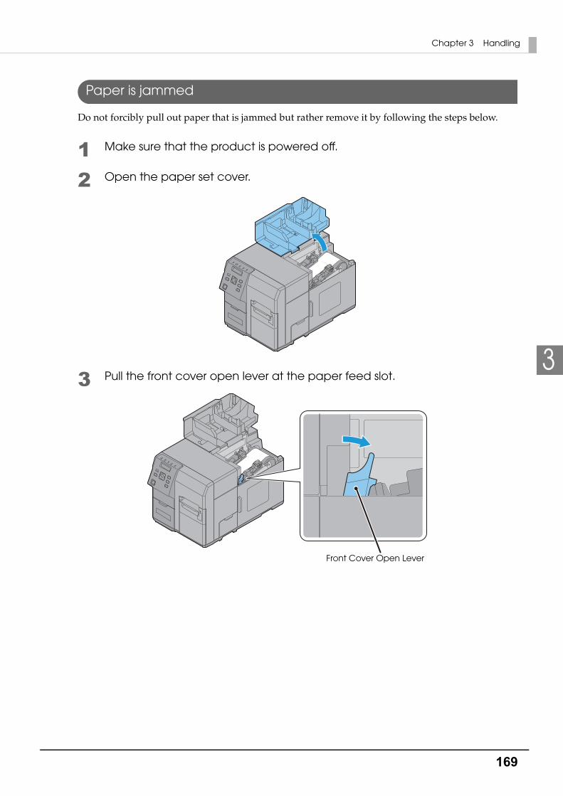
169
Chapter 3 Handling
3
Paper is jammed
Do not forcibly pull out paper that is jammed but rather remove it by following the steps below.
1 Make sure that the product is powered off.
2 Open the paper set cover.
3 Pull the front cover open lever at the paper feed slot.
Front Cover Open Lever
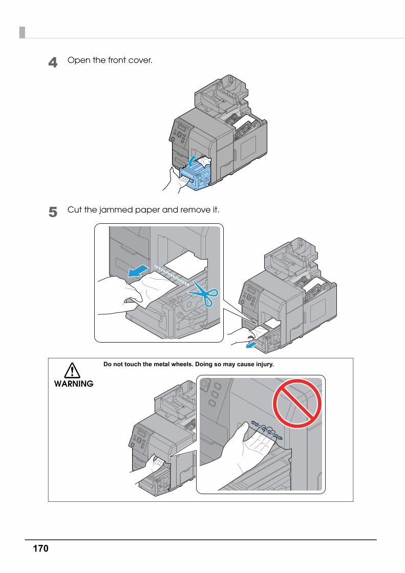
170
4 Open the front cover.
5 Cut the jammed paper and remove it.
WARNING
Do not touch the metal wheels. Doing so may cause injury.

171
Chapter 3 Handling
3
6 Pull out the paper from the paper feed slot.
7 Close the front cover.
8 Set the paper again.See "Setting the Paper" on page 54
CAUTION
Ink may adhere and your fingers may get dirty.

172
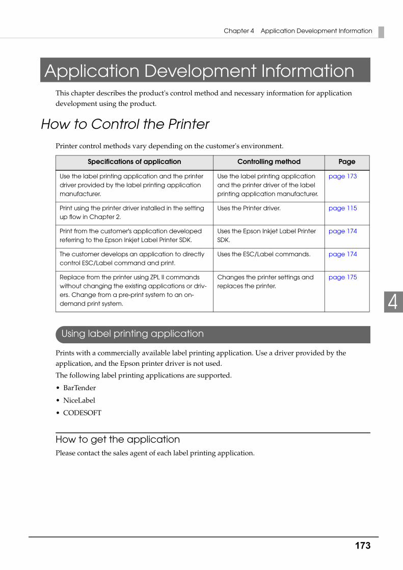
173
Chapter 4 Application Development Information
4
Application Development InformationThis chapter describes the product's control method and necessary information for application development using the product.
How to Control the PrinterPrinter control methods vary depending on the customer's environment.
Using label printing application
Prints with a commercially available label printing application. Use a driver provided by the application, and the Epson printer driver is not used.
The following label printing applications are supported.
• BarTender
• NiceLabel
• CODESOFT
How to get the applicationPlease contact the sales agent of each label printing application.
Specifications of application Controlling method Page
Use the label printing application and the printer driver provided by the label printing application manufacturer.
Use the label printing application and the printer driver of the label printing application manufacturer.
page 173
Print using the printer driver installed in the setting up flow in Chapter 2.
Uses the Printer driver. page 115
Print from the customer's application developed referring to the Epson Inkjet Label Printer SDK.
Uses the Epson Inkjet Label Printer SDK.
page 174
The customer develops an application to directly control ESC/Label command and print.
Uses the ESC/Label commands. page 174
Replace from the printer using ZPL II commands without changing the existing applications or driv-ers. Change from a pre-print system to an on-demand print system.
Changes the printer settings and replaces the printer.
page 175

174
Using the Epson Inkjet Label Printer SDK
The necessary environments to print with a customer's application using an Epson's printer driver are provided as SDK. The following items are included.
Operating Environment
How to get the Install NaviPlease download it from our homepage.
Using the ESC/Label commands
Commands (ESC/Label) to directly print from the customer's application without using a printer driver are provided. For details about the ESC/Label commands, contact your sales agent.
Items included Description
Epson Inkjet Label Printer SDK User’s Guide
This explains the configuration overview of the Epson Inkjet Label Printer SDK, necessary functions to control Epson Inkjet label printers from an application, and settings that need to be performed in a printer driver in advance.
EPDI(EPSON Printer Driver Interface)
The EPDI (EPSON Printer Driver Interface) provides the application programming interface for the Epson's printer driver. By using the EPDI, the Epson's printer driver settings can be performed from application soft-ware the customer is developing.
For explanation of the EPDI and required technical information to use in an application program, refer to the "EPDI for Inkjet Label Printer Refer-ence Manual" that comes with the SDK.
EpsonNet SDK The EpsonNet SDK provides an API to acquire the status of the Epson ink-jet label printer. For explanations of the API and required technical infor-mation to use in an application program, refer to "EpsonNet SDK for Windows Reference" that comes with the SDK.
Label Print Sample Program Execution files of the application and source files of the program are pro-vided, in which printing is performed from Epson inkjet label printers using the Epson Inkjet Label Printer SDK. For how to use the sample program, refer to "Epson Inkjet Label Printer SDK User's Guide".
OS Refer to Appendix
Software A printer driver (installed using the Install Navi).
.NET Framework Ver.3.5 (It is not provided by Epson, customers should pre-pare a printer driver).
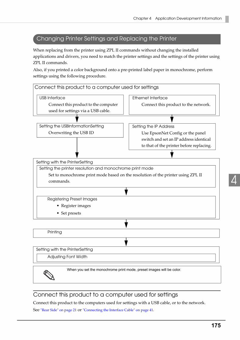
175
Chapter 4 Application Development Information
4
Changing Printer Settings and Replacing the Printer
When replacing from the printer using ZPL II commands without changing the installed applications and drivers, you need to match the printer settings and the settings of the printer using ZPL II commands.
Also, if you printed a color background onto a pre-printed label paper in monochrome, perform settings using the following procedure.
Connect this product to a computer used for settingsConnect this product to the computers used for settings with a USB cable, or to the network.
See "Rear Side" on page 21 or "Connecting the Interface Cable" on page 41.
When you set the monochrome print mode, preset images will be color.
Connect this product to a computer used for settings
USB Interface
Connect this product to the computer used for settings via a USB cable.
Ethernet Interface
Connect this product to the network.
Setting the USBInformationSetting
Overwriting the USB IDSetting the IP Address
Use EpsonNet Config or the panel switch and set an IP address identical to that of the printer before replacing.
Setting the printer resolution and monochrome print mode
Set to monochrome print mode based on the resolution of the printer using ZPL II commands.
Registering Preset Images
• Register images
• Set presets
Printing
Adjusting Font Width
Setting with the PrinterSetting
Setting with the PrinterSetting
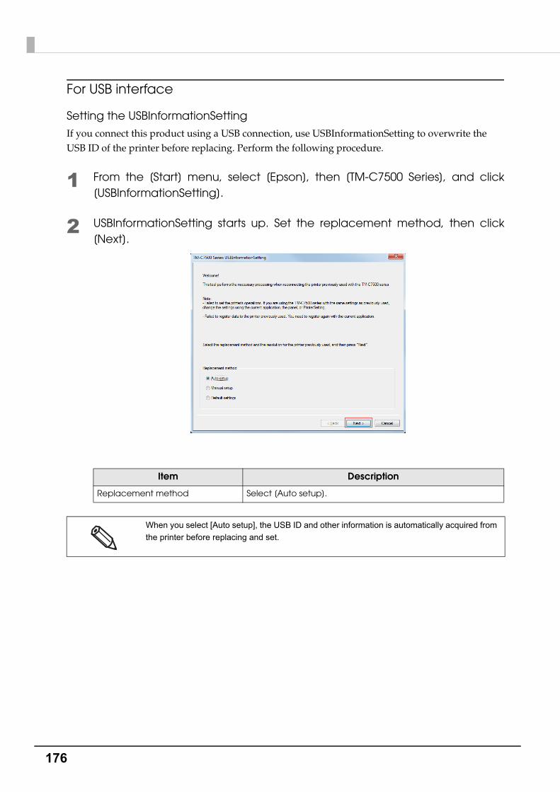
176
For USB interface
Setting the USBInformationSetting
If you connect this product using a USB connection, use USBInformationSetting to overwrite the USB ID of the printer before replacing. Perform the following procedure.
1 From the [Start] menu, select [Epson], then [TM-C7500 Series], and click [USBInformationSetting].
2 USBInformationSetting starts up. Set the replacement method, then click [Next].
Item Description
Replacement method Select [Auto setup].
When you select [Auto setup], the USB ID and other information is automatically acquired from
the printer before replacing and set.
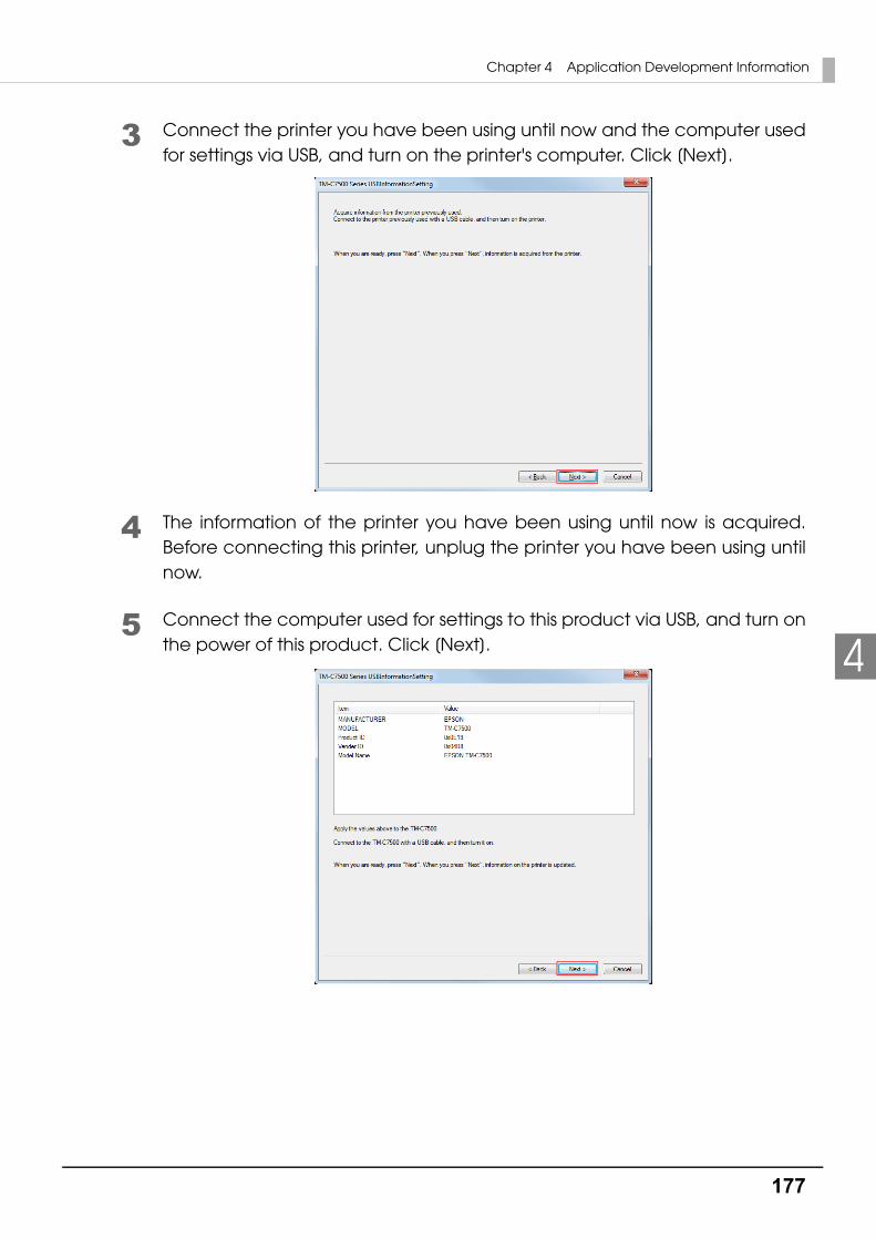
177
Chapter 4 Application Development Information
4
3 Connect the printer you have been using until now and the computer used for settings via USB, and turn on the printer's computer. Click [Next].
4 The information of the printer you have been using until now is acquired. Before connecting this printer, unplug the printer you have been using until now.
5 Connect the computer used for settings to this product via USB, and turn on the power of this product. Click [Next].

178
6 If the settings are changed properly, the following window is displayed. Click [Finish].
7 Turn off this product's power and turn it on again.
For Ethernet interface
Setting the IP Address
Set the IP address of this product.
For the setting method, see "Network settings" on page 67.
Setting the printer resolution and monochrome print modeUse the PrinterSetting to set the printer's resolution based on the resolution of the printer using ZPL II commands. Also set your printer to monochrome print mode. For the setting method, see "Replace settings from printer using ZPL II commands" on page 107.
Registering Preset ImagesUse the PrinterSetting to register preset images.
Registering images
Set the images to be used in preset printing. See "Store data in the printer" on page 99.
Setting preset images
Set the preset images. For the setting method, see "Preset image" on page 101.
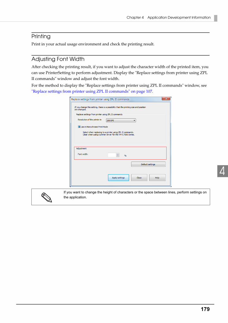
179
Chapter 4 Application Development Information
4
PrintingPrint in your actual usage environment and check the printing result.
Adjusting Font WidthAfter checking the printing result, if you want to adjust the character width of the printed item, you can use PrinterSetting to perform adjustment. Display the "Replace settings from printer using ZPL II commands" window and adjust the font width.
For the method to display the "Replace settings from printer using ZPL II commands" window, see "Replace settings from printer using ZPL II commands" on page 107.
If you want to change the height of characters or the space between lines, perform settings on
the application.

180
Software and ManualsThe following software and manuals are provided for application development.
Software
Software Description ManualProviding method
TM-C7500 Series PrinterSetting
Utility to setup the product in Windows base. For the functions, refer to "PrinterSetting" on page 89.
This document Web or
CD-ROM
EpsonNet Config Software for configuring IP addresses, wire-less LAN, etc. for Epson printers on the net-work.
EpsonNet Config User’s Manual
Web or
CD-ROM
EPSON Monitoring Tool
Utilities to provide the following functions for multiple units of the product connected by network.
Checking status
Changing printer settings
Changing network settings
Monitoring ToolUser’s Manual
Web
USB Printer Class Device Replace-ment Service
Service installed as a resident program on the computerWhen the product is replaced for service or other reason, this detects the printer connection and automatically changes the output printer of the printer driver.This allows the printer to be replaced without changing settings in the application. (The printer is not replaced if a port is specified for the application output destination. The printer is only replaced if the printer driver is specified.)
There is no need to change the USB serial number of the product before replacement.
Included in the supplied CD-ROM.
- Web or
CD-ROM
Color Tone Matching Assistant
Utility to support color adjustment for the illustrations or letters to be printed.
You can check the color tones of the spot color for the illustrations or letters to be printed.
Color Tone Matching Assis-tant User's Guide
Web
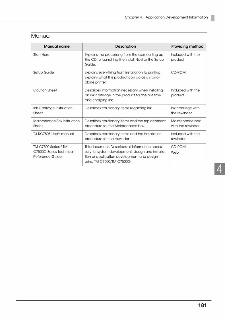
181
Chapter 4 Application Development Information
4
Manual
Manual name Description Providing method
Start Here Explains the processing from the user starting up the CD to launching the Install Navi or the Setup Guide.
Included with the product
Setup Guide Explains everything from installation to printing. Explains what this product can do as a stand-alone printer.
CD-ROM
Caution Sheet Describes information necessary when installing an ink cartridge in the product for the first time and charging ink.
Included with the product
Ink Cartridge Instruction Sheet
Describes cautionary items regarding ink. Ink cartridge with the rewinder
Maintenance Box Instruction Sheet
Describes cautionary items and the replacement procedure for the Maintenance box.
Maintenance box with the rewinder
TU-RC7508 User's manual Describes cautionary items and the installation procedure for the rewinder.
Included with the rewinder
TM-C7500 Series / TM-C7500G Series Technical Reference Guide
This document. Describes all information neces-sary for system development, design and installa-tion or application development and design using TM-C7500/TM-C7500G.
CD-ROM
Web
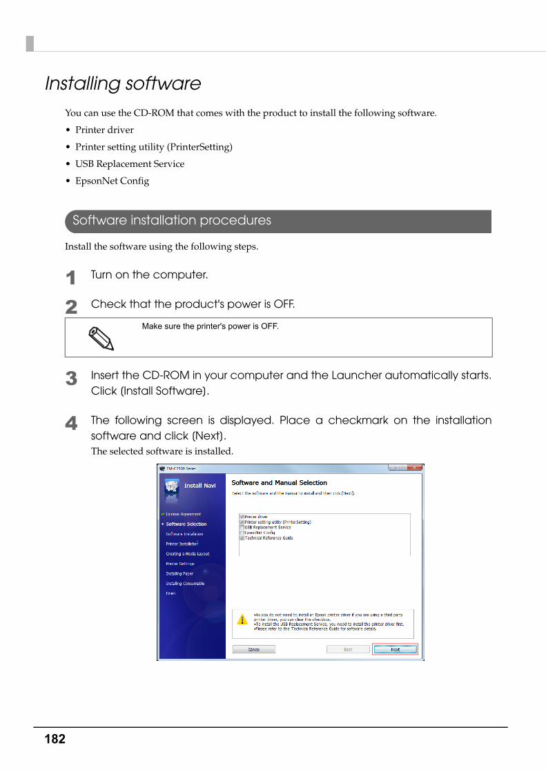
182
Installing softwareYou can use the CD-ROM that comes with the product to install the following software.
• Printer driver
• Printer setting utility (PrinterSetting)
• USB Replacement Service
• EpsonNet Config
Software installation procedures
Install the software using the following steps.
1 Turn on the computer.
2 Check that the product's power is OFF.
3 Insert the CD-ROM in your computer and the Launcher automatically starts.Click [Install Software].
4 The following screen is displayed. Place a checkmark on the installation software and click [Next].The selected software is installed.
Make sure the printer's power is OFF.
183
Chapter 4 Application Development Information
4
Precaution when using the product with Ethernet connectionWhen using the product with an Ethernet connection, it cannot be used just by installing the printer driver. Add this product with the following steps.
1 Install the printer driver.
2 Turn on the product.
3 Open the [Devices and Printers].See "How to Display the Printer Driver" on page 78
4 Execute [Add a printer] and add the product following the instructions on the screen.
In the printer driver installation screen that is displayed during the procedure, select "Epson" as
the manufacturer and "EPSON TM-C7500" as the printer.

184
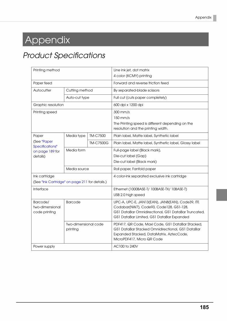
185
Appendix
Appendix
Product Specifications
Printing method Line ink jet, dot matrix
4 color (KCMY) printing
Paper feed Forward and reverse friction feed
Autocutter Cutting method By separated-blade scissors
Auto-cut type Full cut (cuts paper completely)
Graphic resolution 600 dpi x 1200 dpi
Printing speed 300 mm/s
150 mm/s
The Printing speed is different depending on the resolution and the printing width.
Paper
(See "Paper Specifications" on page 189 for details)
Media type TM-C7500 Plain label, Matte label, Synthetic label
TM-C7500G Plain label, Matte label, Synthetic label, Glossy label
Media form Full-page label (Black mark),
Die-cut label (Gap)
Die-cut label (Black mark)
Media source Roll paper, Fanfold paper
Ink cartridge
(See "Ink Cartridge" on page 211 for details.)
4 color-ink separated exclusive ink cartridge
Interface Ethernet (1000BASE-T/ 100BASE-TX/ 10BASE-T)
USB 2.0 high speed
Barcode/two-dimensional code printing
Barcode UPC-A, UPC-E, JAN13(EAN), JAN8(EAN), Code39, ITF, Codabar(NW7), Code93, Code128, GS1-128, GS1 DataBar Omnidirectional, GS1 DataBar Truncated, GS1 DataBar Limited, GS1 DataBar Expanded
Two-dimensional code printing
PDF417, QR Code, Maxi Code, GS1 DataBar Stacked, GS1 DataBar Stacked Omnidirectional, GS1 DataBar Expanded Stacked, DataMatrix, AztecCode, MicroPDF417, Micro QR Code
Power supply AC100 to 240V
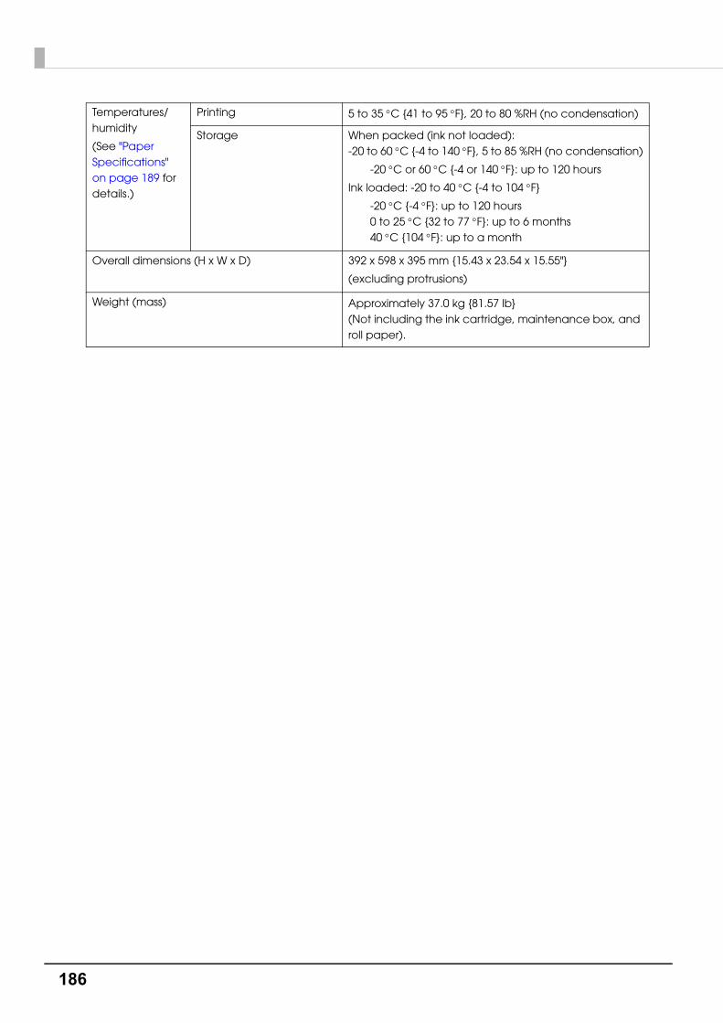
186
Temperatures/humidity
(See "Paper Specifications" on page 189 for details.)
Printing 5 to 35 C {41 to 95 F}, 20 to 80 %RH (no condensation)
Storage When packed (ink not loaded): -20 to 60 C {-4 to 140 F}, 5 to 85 %RH (no condensation)
-20 C or 60 C {-4 or 140 F}: up to 120 hours
Ink loaded: -20 to 40 C {-4 to 104 F}
-20 C {-4 F}: up to 120 hours0 to 25 C {32 to 77 F}: up to 6 months40 C {104 F}: up to a month
Overall dimensions (H x W x D) 392 x 598 x 395 mm {15.43 x 23.54 x 15.55"}
(excluding protrusions)
Weight (mass) Approximately 37.0 kg {81.57 lb} (Not including the ink cartridge, maintenance box, and roll paper).

187
Appendix
Operating Environment
OS Microsoft Windows 8.1 (32 bit/ 64 bit)
Microsoft Windows 8 (32 bit/ 64 bit)
Microsoft Windows 7 SP1 (32 bit/ 64 bit)
Microsoft Windows Vista SP2 (32 bit/ 64 bit)
Microsoft Windows XP SP3 (32 bit)
Microsoft Windows Server 2012 R2
Microsoft Windows Server 2012
Microsoft Windows Server 2008 R2
Microsoft Windows Server 2008 (32 bit/ 64 bit)
Microsoft Windows Server 2003 R2 (32 bit)
Computer Must support the following computers that run the above operating systems.
PC/AT compatible
CPU Conforms to the operating environment of the OS.
(For Windows 8.1/ Windows 8/ Windows 7/ Windows Vista/ Windows XP/ Windows Server 2012/ Windows Server 2008/ Windows Server 2003: Computer equipped with Pentium 4 2GHz or better processor is recommended. Intel Pentium/ Celeron series or AMD Athlon/ Duron family processor, or processor interchangeable with these, is recommended.)
Memory Conforms to the operating environment of the OS.
(For Windows 8.1/ Windows 8/ Windows 7/ Windows Vista/ Windows XP/ Windows Server 2012/ Windows Server 2008/ Windows Server 2003:1GB or higher is recommended.)
HDD Conforms to the operating environment of the OS.
(For Windows 8.1/ Windows 8/ Windows 7/ Windows Vista/ Windows XP/ Windows Server 2012/ Windows Server 2008/ Windows Server 2003: Must have at least 250 MB free space.)
The above requirements may conflict with the minimum requirements of the operating system
supported. If so, the operating system’s minimum requirements take precedence.

188
Printing Specifications
Printable Area
Printing speed
*1 dpi: dots per 25.4 mm (dots per inch)
*2 The maximum Printing speed is the maximum speed during printing, but excluding head cleaning, autocutting, print job start/end processing and periodic flushing.
*3 The average Printing speed is the average speed during printing, including periodic flushing, but excluding head cleaning, autocutting and print job start/end processing.
Roll paper Minimum 46 mm {1.81”}, Maximum 108 mm {4.25”}
Fanfold paper Minimum 46 mm {1.81”}, Maximum 108 mm {4.25”}
During printing Head
maintenance mode
Input resolution *1
(width x length)
Graphic resolution *1
(width x length)
Flushing on paper
Maximum Printing
speed *2
Average printing speed *3
Continuous Printing
600 x 600 dpi 600 x 1200 dpi Standard 300 mm/s {11.81"/s}
150 mm/s {5.91"/s}
300 mm/s {11.81"/s}
150 mm/s {5.91"/s}
Pause for Maintenance (Intermittent printing)
600 x 600 dpi 600 x 1200 dpi few 300 mm/s {11.81"/s}
150 mm/s {5.91"/s}
Around 220 mm/s {8.66"/s}
Around 110 mm/s {4.33"/s}
Printing speed may slow down, depending on the data transmission speed.
The average printing speed may be lower in high temperature conditions exceeding 35 C
{95 F}.

189
Appendix
Paper Specifications
The following is the type and the size of paper specified for this printer.
• TM-C7500
When using paper other than the specified, users must evaluate the recognition rate in
advance to avoid deterioration of the paper feed accuracy/barcode recognition rate/print
quality and frequent occurrence of paper jams.
Depending on the temperature and humidity, the synthetic labels and paper backing have
different ratios of expansion and contraction, and this causes the paper to curl. If the paper
curls, the paper may be rubbed by the print head and become contaminated, or the paper
may jam.
Do not use the paper which is extended by connecting with tape and others. The paper may
be detected incorrectly by the connected line, and rubbed by the print head and become
contaminated, or the paper may jam.
Media form Media type Media source Width
Full-page label (Black mark) Plain label
Matte label
Synthetic label
Roll paper 50 mm to 112 mm {1.97 to 4.41"}
(Backing paper width)
46 to 108 mm {1.81 to 4.25"}
(Label width)
Die-cut label (Gap) Plain label
Matte label
Synthetic label
Roll paper 50 mm to 112 mm {1.97 to 4.41"}
(Backing paper width)
46 to 108 mm {1.81 to 4.25"}
(Label width)
Die-cut label (Black mark) Plain label
Matte label
Synthetic label
Roll paper
Fanfold paper
50 mm to 112 mm {1.97 to 4.41"}
(Backing paper width)
46 to 108 mm {1.81 to 4.25"}
(Label width)
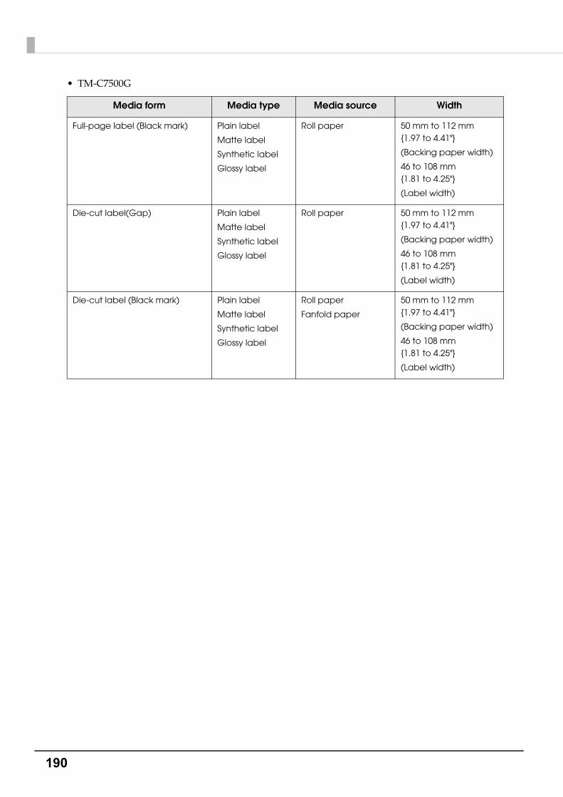
190
• TM-C7500G
Media form Media type Media source Width
Full-page label (Black mark) Plain label
Matte label
Synthetic label
Glossy label
Roll paper 50 mm to 112 mm {1.97 to 4.41"}
(Backing paper width)
46 to 108 mm {1.81 to 4.25"}
(Label width)
Die-cut label(Gap) Plain label
Matte label
Synthetic label
Glossy label
Roll paper 50 mm to 112 mm {1.97 to 4.41"}
(Backing paper width)
46 to 108 mm {1.81 to 4.25"}
(Label width)
Die-cut label (Black mark) Plain label
Matte label
Synthetic label
Glossy label
Roll paper
Fanfold paper
50 mm to 112 mm {1.97 to 4.41"}
(Backing paper width)
46 to 108 mm {1.81 to 4.25"}
(Label width)
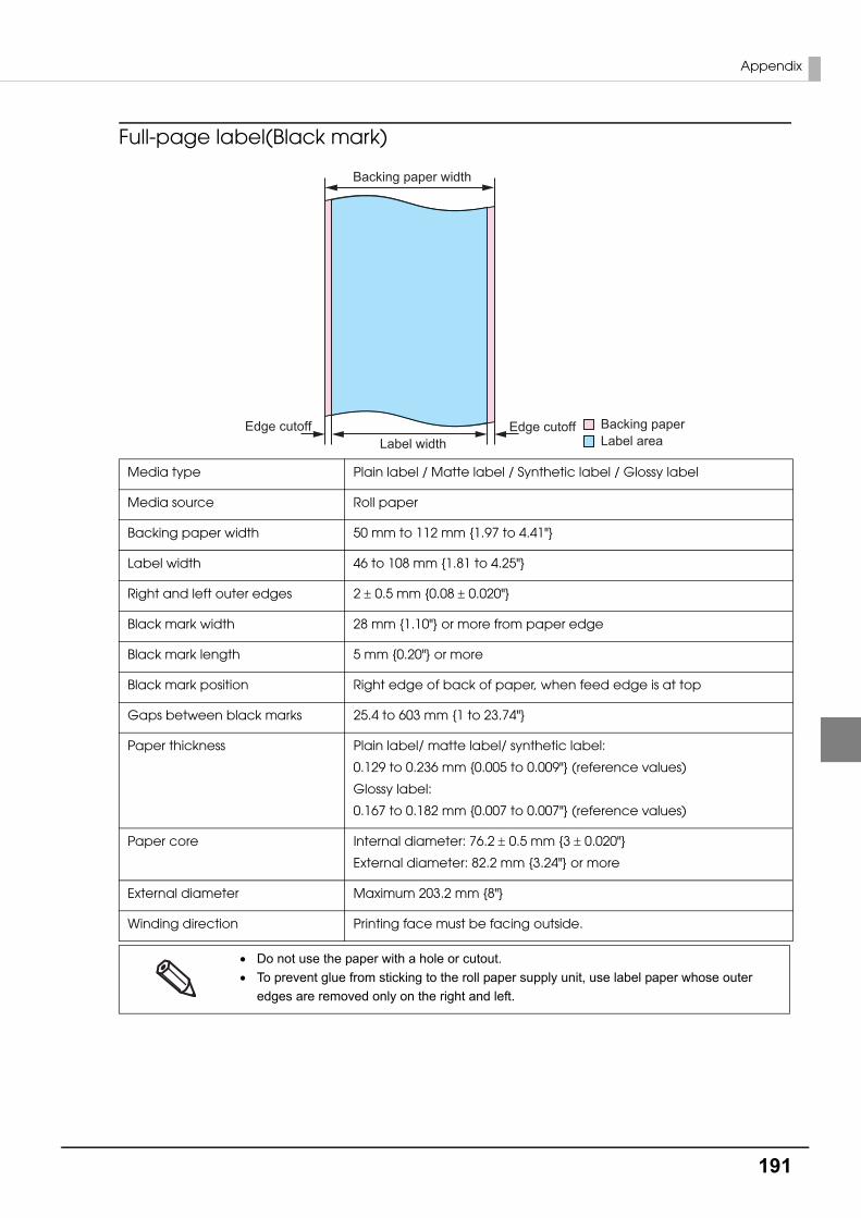
191
Appendix
Full-page label(Black mark)
Media type Plain label / Matte label / Synthetic label / Glossy label
Media source Roll paper
Backing paper width 50 mm to 112 mm {1.97 to 4.41"}
Label width 46 to 108 mm {1.81 to 4.25"}
Right and left outer edges 2 0.5 mm {0.08 0.020"}
Black mark width 28 mm {1.10"} or more from paper edge
Black mark length 5 mm {0.20"} or more
Black mark position Right edge of back of paper, when feed edge is at top
Gaps between black marks 25.4 to 603 mm {1 to 23.74"}
Paper thickness Plain label/ matte label/ synthetic label:
0.129 to 0.236 mm {0.005 to 0.009"} (reference values)
Glossy label:
0.167 to 0.182 mm {0.007 to 0.007"} (reference values)
Paper core Internal diameter: 76.2 0.5 mm {3 0.020"}
External diameter: 82.2 mm {3.24"} or more
External diameter Maximum 203.2 mm {8"}
Winding direction Printing face must be facing outside.
Do not use the paper with a hole or cutout.
To prevent glue from sticking to the roll paper supply unit, use label paper whose outer
edges are removed only on the right and left.
Label areaBacking paper
Backing paper width
Label widthEdge cutoffEdge cutoff

192
Die-cut label(Gap)
Media type Plain label / Matte label / Synthetic label / Glossy label
Media source Roll paper
Backing paper width 50 mm to 112 mm {1.97 to 4.41"}
Label width 46 to 108 mm {1.81 to 4.25"}
Label length 25.4 to 600 mm {1 to 23.62"}
Gap between labels 3 to 6 mm {0.12 to 0.24"}
Left and right outer edges 2 0.5 mm {0.08 0.020"}
Label edge R 1.5 mm {0.06"} or less
Paper thickness Plain label/ Matte label/ Synthetic label:
0.129 to 0.236 mm {0.005 to 0.009"} (reference values)
Glossy label:
0.167 to 0.182 mm {0.007 to 0.007"} (reference values)
Paper core Internal diameter: 76.2 0.5 mm {3 0.020"}
External diameter: 82.2 mm {3.24"} or more
External diameter Maximum 203.2 mm {8"}
Winding direction Printing face must be facing outside.
Do not use the paper with a hole or cutout.
If the backing is synthetic paper or film, it will be difficult to cut by hand even if there is a per-
foration, so do not use the perforation.
Label areaBacking paper
Backing paper width
Edge R
Labe
l len
gth
Gap
bet
wee
n la
bels
Edge cutoffEdge cutoff Label width
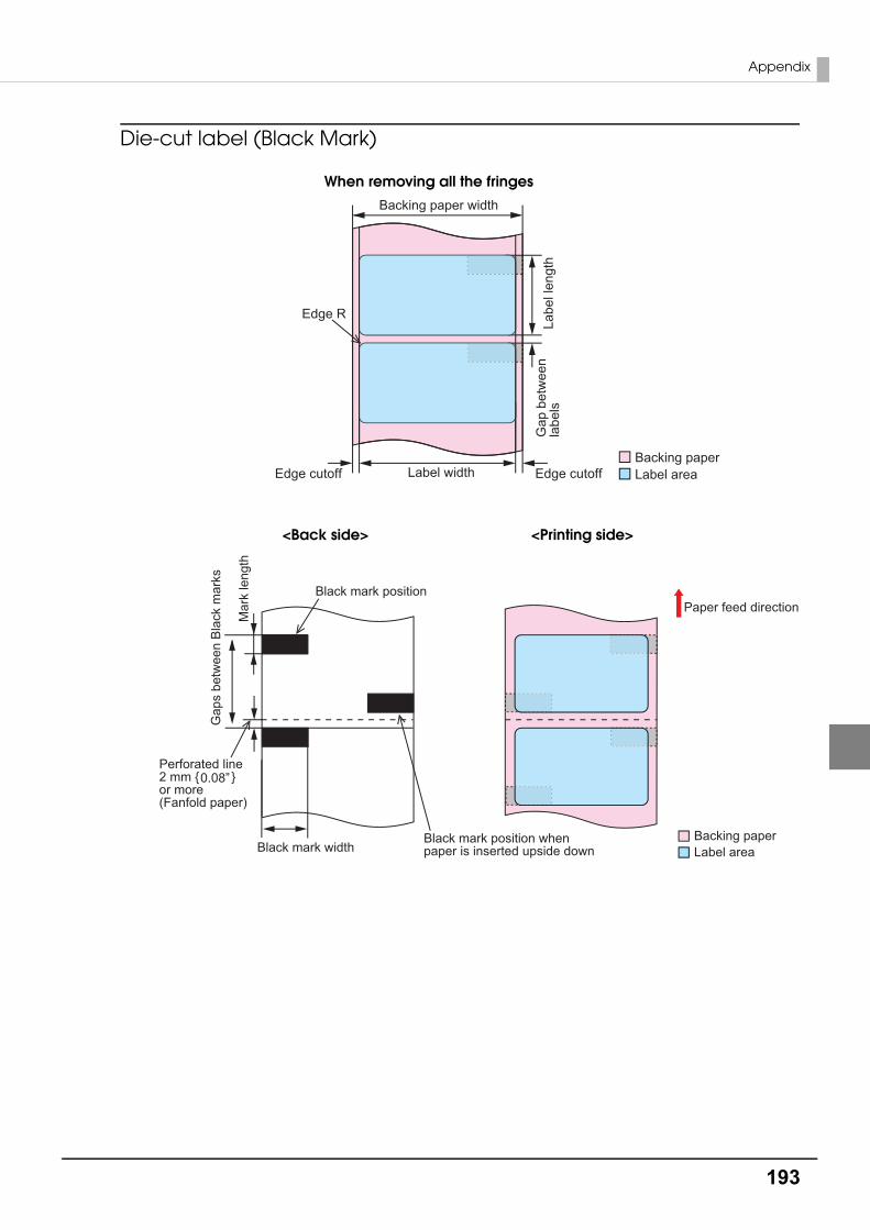
193
Appendix
Die-cut label (Black Mark)
Label areaBacking paper
Backing paper width
Edge R
Labe
l len
gth
Gap
bet
wee
n la
bels
Edge cutoffEdge cutoff Label width
When removing all the fringes
Black mark position
Black mark width
Mar
k le
ngth
Gap
s be
twee
n Bl
ack
mar
ks
Black mark position when paper is inserted upside down
Paper feed direction
Label areaBacking paper
Perforated line2 mm { }or more(Fanfold paper)
0.08”
<Back side> <Printing side>
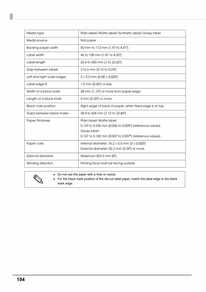
194
Media type Plain label/ Matte label/ Synthetic label/ Glossy label
Media source Roll paper
Backing paper width 50 mm to 112 mm {1.97 to 4.41"}
Label width 46 to 108 mm {1.81 to 4.25"}
Label length 25.4 to 600 mm {1 to 23.62"}
Gap between labels 3 to 6 mm {0.12 to 0.24"}
Left and right outer edges 2 0.5 mm {0.08 0.020"}
Label edge R 1.5 mm {0.06"} or less
Width of a black mark 28 mm {1.10"} or more from paper edge
Length of a black mark 5 mm {0.20"} or more
Black mark position Right edge of back of paper, when feed edge is at top
Gaps between black marks 28.4 to 606 mm {1.12 to 23.86"}
Paper thickness Plain label/ Matte label:
0.129 to 0.236 mm {0.006 to 0.009"} (reference values)
Glossy label:
0.167 to 0.182 mm {0.007 to 0.007"} (reference values)
Paper core Internal diameter: 76.2 0.5 mm {3 0.020"}
External diameter: 82.2 mm {3.24"} or more
External diameter Maximum 203.2 mm {8"}
Winding direction Printing face must be facing outside.
Do not use the paper with a hole or cutout.
For the black mark position of the die-cut label paper, match the label edge to the black
mark edge.

195
Appendix
Media type Plain label / Matte label
Media source Fanfold paper
Backing paper width 50 to 112 mm {1.97 to 4.41"}
Label width 46 to 108 mm {1.81 to 4.25"}
Label length 25.4 to 301.8 mm {1 to 11.88"}
Gap between labels 3 to 6 mm {0.12 to 0.24"}
Left and right outer edges 2 mm 0.5 mm {0.08 0.020"}
Label edge R 1.5 mm {0.06"} or less
Width of a black mark 28 mm {1.10"} or more from paper edge
Length of a black mark 5 mm {0.20"} or more
Black mark position Right edge of back of paper, when feed edge is at top
Gaps between black marks 28.4 to 304.8 mm {1.12 to 12.0"}
Paper thickness 0.161 to 0.164 mm {0.006 to 0.006"} (reference value)
Perforated line pitch 203.2 to 304.8 mm {8 to 12"}
Form of perforated line 1 mm {0.039"} uncut, 5 mm {0.20"} cut
Number of folds 750 or less
Do not use the paper with a hole or cutout.
Autocutting on the perforated lines may generate minute paper dust, causing machine prob-
lems. Also, autocutting ahead of the perforated line may cause problems when feeding
paper. Therefore, autocutting must be performed 0.5 mm to 1 mm {0.02 to 0.039"} behind
the perforated line.
Therefore, set the black mark position 2 mm {0.08"} or more from the perforation.
For the black mark position of the die-cut label paper, match the label edge to the black
mark edge.
The perforations on both sides of the paper shall be uncut.
Perforated line
Length of the uncut portion
Length of the portion
1 mm { }0.04” 1 mm { }0.04”
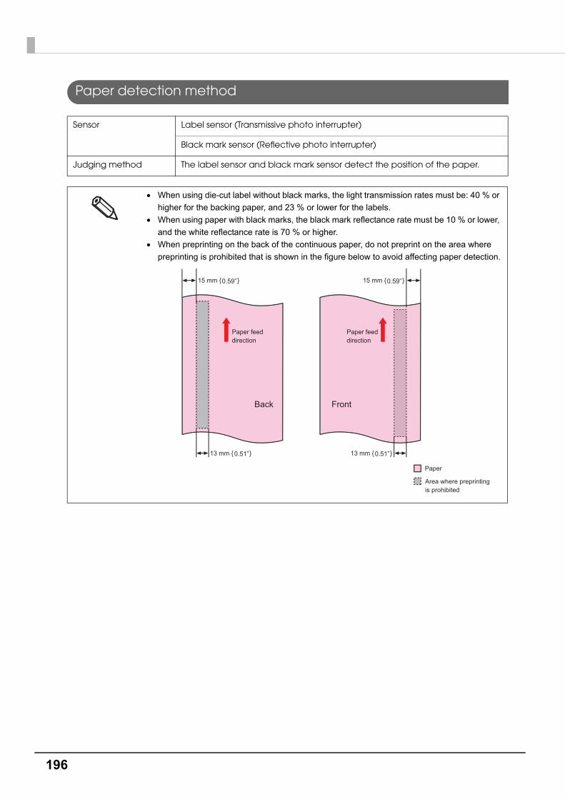
196
Paper detection method
Sensor Label sensor (Transmissive photo interrupter)
Black mark sensor (Reflective photo interrupter)
Judging method The label sensor and black mark sensor detect the position of the paper.
When using die-cut label without black marks, the light transmission rates must be: 40 % or
higher for the backing paper, and 23 % or lower for the labels.
When using paper with black marks, the black mark reflectance rate must be 10 % or lower,
and the white reflectance rate is 70 % or higher.
When preprinting on the back of the continuous paper, do not preprint on the area where
preprinting is prohibited that is shown in the figure below to avoid affecting paper detection.
15 mm { }
13 mm { }
Paper feed direction
Paper feed direction
Area where preprinting is prohibited
Back Front
Paper
0.59” 15 mm { }0.59”
0.51” 13 mm { }0.51”
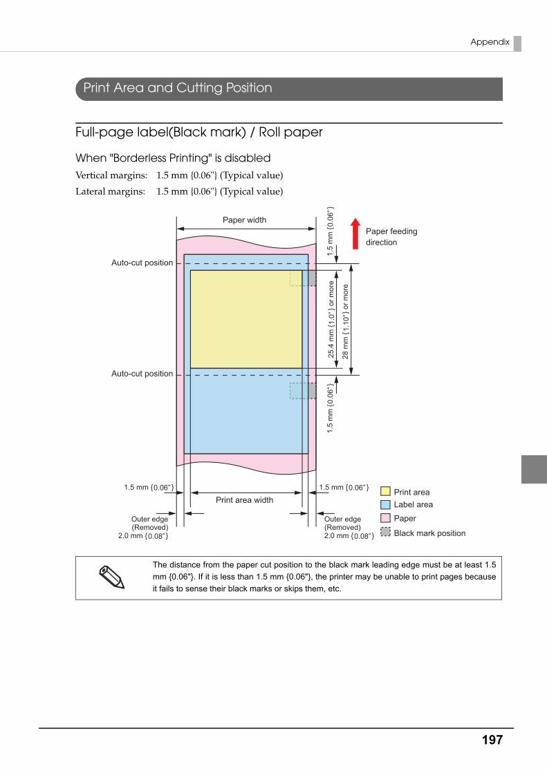
197
Appendix
Print Area and Cutting Position
Full-page label(Black mark) / Roll paper
When "Borderless Printing" is disabled
Vertical margins: 1.5 mm {0.06"} (Typical value)
Lateral margins: 1.5 mm {0.06"} (Typical value)
The distance from the paper cut position to the black mark leading edge must be at least 1.5
mm {0.06"}. If it is less than 1.5 mm {0.06"}, the printer may be unable to print pages because
it fails to sense their black marks or skips them, etc.
Black mark position
Paper
Label areaPrint area
Auto-cut position
Auto-cut position
Print area width
Paper widthPaper feeding direction
1.5
mm
{
}
0.06
”1.
5 m
m {
}0.
06”
1.5 mm { }0.06” 1.5 mm { }0.06”
25.4
mm
{
} o
r mor
e1.
0”
28 m
m {
} o
r mor
e1.
10”
Outer edge(Removed)
2.0 mm { }0.08”
Outer edge(Removed)2.0 mm { }0.08”

198
When "Borderless Printing" is enabled
Vertical margins: 1.5 mm {0.06"} (Typical value)
Lateral margins: 0 mm (Typical value)
If you enabled "Extend Printable Area", printing is done with settings for no margins, but the
printing might protrude beyond the paper/label, depending on the actual print position and
the set position for the paper/ label. To make sure printing doesn’t protrude out, ensure mar-
gins of 1.5 mm {0.06"} or more in the print data.
The distance from the paper cut position to the black mark leading edge must be at least 1.5
mm {0.06"}. If it is less than 1.5 mm {0.06"}, the printer may be unable to print pages
because it fails to sense their black marks or skips them, etc.
Black mark position
Paper
Label areaPrint area
Auto-cut position
Auto-cut position
Print area width
Paper widthPaper feeding direction
1.5
mm
{
}
0.06
”1.
5 m
m {
}0.
06”
25.4
mm
{
} o
r mor
e1.
0”
28 m
m {
} o
r mor
e1.
10”
Outer edge(Removed)
2.0 mm { }0.08”
Outer edge(Removed)2.0 mm { }0.08”

199
Appendix
Die-cut label(Gap) / Roll paper
When "Borderless Printing" is disabled
Vertical margins: 1.5 mm {0.06"} (Typical value)
Lateral margins: 1.5 mm {0.06"} (Typical value)
Black mark positionLabel areaPrint area
Print area width
Auto-cut position
Auto-cut position
Perforated line
Paper width
Paper feeding direction
Outer edge(Removed)
2.0 mm { }0.08”
Outer edge(Removed)2.0 mm { }0.08”
1.5 mm { }0.06” 1.5 mm { }0.06”
25.4
mm
{
} o
r mor
e1.
0”
28.4
mm
{
}
or m
ore
1.12
”
22.4
mm
{
}
or m
ore
0.88
”1.
5 m
m {
}0.
06”
1.5
mm
{
}
0.06
”
1.5
mm
{
}
0.06
”
1.5
mm
{
}
0.06
”
0.5
to 1
mm
{
}
0.02
to 0
.04”
Inte
rval
bet
wee
n la
bels
3.0
mm
{
}
0.12
”

200
When "Borderless Printing" is enabled
Vertical margins: 0 mm (Typical value)
Lateral margins: 0 mm (Typical value)
If you enabled “Extend Printable Area”, printing is done with settings for no margins, but the
printing might protrude beyond the paper/ label, depending on the actual print position and the
set position for the paper/ label. To make sure printing doesn’t protrude out, ensure margins of
1.5 mm {0.06"} or more in the print data.
Black mark positionLabel area
Print area
Print area width
Auto-cut position
Auto-cut position
Perforated line
Paper width
Paper feeding direction
Outer edge(Removed)
2.0 mm { }0.08”
Outer edge(Removed)2.0 mm { }0.08”
25.4
mm
{
} o
r mor
e1.
0”
28.4
mm
{
}
or m
ore
1.12
”
1.5
mm
{
}
0.06
”
0.5
to 1
mm
{
}
0.02
to 0
.04”
Inte
rval
bet
wee
n la
bels
3.0
mm
{
}
0.12
”
1.5
mm
{
}
0.06
”
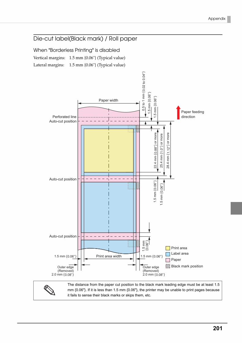
201
Appendix
Die-cut label(Black mark) / Roll paper
When "Borderless Printing" is disabled
Vertical margins: 1.5 mm {0.06"} (Typical value)
Lateral margins: 1.5 mm {0.06"} (Typical value)
The distance from the paper cut position to the black mark leading edge must be at least 1.5
mm {0.06"}. If it is less than 1.5 mm {0.06"}, the printer may be unable to print pages because
it fails to sense their black marks or skips them, etc.
Print area width
Auto-cut position
Auto-cut position
Auto-cut position
Perforated line
Paper width
Paper feeding direction
Black mark position
Paper
Label areaPrint area
25.4
mm
{
} o
r mor
e1.
0”
28.4
mm
{
}
or m
ore
1.12
”
22.4
mm
{
}
or m
ore
0.88
”1.
5 m
m {
}0.
06”
1.5
mm
{
}
0.06
”
0.5
to 1
mm
{
}
0.02
to 0
.04”
1.5
mm
{
}
0.06
”
1.5
mm
{
}
0.06
”
Outer edge(Removed)
2.0 mm { }0.08”
Outer edge(Removed)2.0 mm { }0.08”
1.5 mm { }0.06” 1.5 mm { }0.06”
1.5
mm
{
}
0.06
”

202
When "Borderless Printing" is enabled
Vertical margins: 0 mm (Typical value)
Lateral margins: 0 mm (Typical value)
If you enabled “Extend Printable Area”, printing is done with settings for no margins, but the
printing might protrude beyond the paper/ label, depending on the actual print position and
the set position for the paper/ label. To make sure printing doesn’t protrude out, ensure
margins of 1.5 mm {0.06"} or more in the print data.
The distance from the paper cut position to the black mark leading edge must be at least 1.5
mm {0.06"}. If it is less than 1.5 mm {0.06"}, the printer may be unable to print pages
because it fails to sense their black marks or skips them, etc.
Black mark position
Paper
Label areaPrint area
Print area width
Paper width
Paper feeding direction
Auto-cut position
Auto-cut position
Auto-cut position
Perforated line
1.5
mm
{
}
0.06
”
Outer edge(Removed)
2.0 mm { }0.08”
Outer edge(Removed)2.0 mm { }0.08”
1.5
mm
{
}
0.06
”25
.4 m
m {
} or m
ore
1.0”
28.4
mm
{
}
or m
ore
1.12
”
1.5
mm
{
}
0.06
”
0.5
to 1
mm
{
}
0.02
to 0
.04”
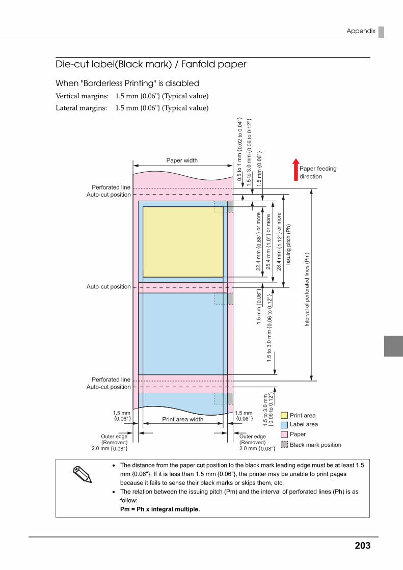
203
Appendix
Die-cut label(Black mark) / Fanfold paper
When "Borderless Printing" is disabled
Vertical margins: 1.5 mm {0.06"} (Typical value)
Lateral margins: 1.5 mm {0.06"} (Typical value)
The distance from the paper cut position to the black mark leading edge must be at least 1.5
mm {0.06"}. If it is less than 1.5 mm {0.06"}, the printer may be unable to print pages
because it fails to sense their black marks or skips them, etc.
The relation between the issuing pitch (Pm) and the interval of perforated lines (Ph) is as
follow: Pm = Ph x integral multiple.
Auto-cut position
Auto-cut positionPerforated line
Auto-cut positionPerforated line
Paper widthPaper feeding direction
Black mark position
Paper
Label areaPrint areaPrint area width
Issu
ing
pitc
h (P
h)
Inte
rval
of p
erfo
rate
d lin
es (P
m)
Outer edge(Removed)
2.0 mm { }0.08”
Outer edge(Removed)2.0 mm { }0.08”
0.5
to 1
mm
{
}
0.02
to 0
.04”
1.5
to 3
.0 m
m {
}0.
06 to
0.1
2”
1.5
mm
{
}
0.06
”
25.4
mm
{
} o
r mor
e1.
0”
28.4
mm
{
}
or m
ore
1.12
”
22.4
mm
{
}
or m
ore
0.88
”
1.5
to 3
.0 m
m {
}0.
06 to
0.1
2”
1.5
mm
{
}
0.06
”1.
5 to
3.0
mm
{
}0.
06 to
0.1
2”
1.5 mm { }0.06”
1.5 mm { }0.06”

204
When "Borderless Printing" is enabled
Vertical margins: 0 mm (Typical value)
Lateral margins: 0 mm (Typical value)
If you enabled “Extend Printable Area”, printing is done with settings for no margins, but the
printing might protrude beyond the paper/ label, depending on the actual print position and
the set position for the paper/ label. To make sure printing doesn’t protrude out, ensure
margins of 1.5 mm {0.06"} or more in the print data.
The distance from the paper cut position to the black mark leading edge must be at least 1.5
mm {0.06"}. If it is less than 1.5 mm {0.06"}, the printer may be unable to print pages
because it fails to sense their black marks or skips them, etc.
Black mark position
Paper
Label areaPrint area
Print area width
Paper width Paper feeding direction
Issu
ing
pitc
h (P
h)
Inte
rval
of p
erfo
rate
d lin
es (P
m)
Auto-cut position
Auto-cut positionPerforated line
Auto-cut positionPerforated line
Outer edge(Removed)
2.0 mm { }0.08”
Outer edge(Removed)2.0 mm { }0.08”
1.5
to 3
.0 m
m
{
}
0.06
to 0
.12”
1.5
to 3
.0 m
m {
}0.
06 to
0.1
2”
0.5
to 1
mm
{
}
0.02
to 0
.04”
1.5
to 3
.0 m
m {
}0.
06 to
0.1
2”25
.4 m
m {
} or m
ore
1.0”
28.4
mm
{
}
or m
ore
1.12
”

205
Appendix
Electrical Characteristics
*: The operating power consumption is based on Epson operating conditions.
Power supply Power supplied via power source connector
Input voltage (rated) 100 to 240 V, 1.1 A
Frequency (rated) 50 Hz to 60 Hz
Power consumption
Operating 100 V: Average Approximately 84 WPeak Approximately 123 W
230 V: Average Approximately 81 WPeak Approximately 102 W
Idling 100 V: Average Approximately 5.1 W
230 V: Average Approximately 5.4 W
When power is OFF
100 V: Average Approximately 0.2 W
230 V: Average Approximately 0.5 W
Use the dedicated AC cable included in the product package.
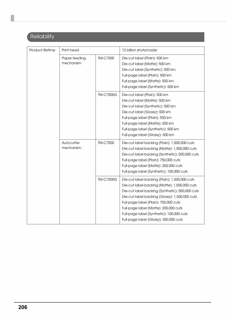
206
Reliability
Product lifetime Print head 12 billion shots/nozzle
Paper feeding mechanism
TM-C7500 Die-cut label (Plain): 500 km
Die-cut label (Matte): 500 km
Die-cut label (Synthetic): 500 km
Full-page label (Plain): 500 km
Full-page label (Matte): 500 km
Full-page label (Synthetic): 500 km
TM-C7500G Die-cut label (Plain): 500 km
Die-cut label (Matte): 500 km
Die-cut label (Synthetic): 500 km
Die-cut label (Glossy): 500 km
Full-page label (Plain): 500 km
Full-page label (Matte): 500 km
Full-page label (Synthetic): 500 km
Full-page label (Glossy): 500 km
Autocutter mechanism
TM-C7500 Die-cut label backing (Plain): 1,500,000 cuts
Die-cut label backing (Matte): 1,500,000 cuts
Die-cut label backing (Synthetic): 500,000 cuts
Full-page label (Plain): 750,000 cuts
Full-page label (Matte): 200,000 cuts
Full-page label (Synthetic): 100,000 cuts
TM-C7500G Die-cut label backing (Plain): 1,500,000 cuts
Die-cut label backing (Matte): 1,500,000 cuts
Die-cut label backing (Synthetic): 500,000 cuts
Die-cut label backing (Glossy): 1,500,000 cuts
Full-page label (Plain): 750,000 cuts
Full-page label (Matte): 200,000 cuts
Full-page label (Synthetic): 100,000 cuts
Full-page label (Glossy): 300,000 cuts

207
Appendix
Environmental Conditions
Item Specification
Temperatures/humidity
Printing 5 to 35 C {41 to 95 F}, 20 to 80 %RH (no condensation)
Barcode printing 15 to 35 C {59 to 95 F}, 20 to 80 %RH (no condensation)
Storage When packed (No condensation, ink not loaded):
-20 to 60 C {-4 to 140 F}, 5 to 85 %RH(At -20 or 60 C {-4 or 140 F}: up to 120 hours)
With ink loaded -20 to 40 C {-4 to 104 F}
(At -20 C {-4 F}: up to 120 hours)
(At 0 to 25 C: {32 to 77 F}: up to 6 months)
(At 40 C {104 F}: up to 1 month)
Absolute maximum rated 70 C {158 F}
Pressure (elevation)
Operating 700 to 1060 hPa (approximately 0 to 2,500 m above sea level) {approximately 0 to 98425.20”}
Not operating(including in transportation)
700 to 1060 hPa (approximately 0 to 2,500 m above sea level) {approximately 0 to 98425.20”}
Vibration resistance
When packed Frequency: 5 to 55 Hz
Acceleration: Approximately 19.6 m/s2 {2 G}
Sweep: 10 minutes (half cycle)
Time: 1 hour
Orientation: x, y, and z
Shock resistance
When packed Packing: Epson standard package specifications
Height: 45 cm {17.72"}
Orientation: 1 corner, 3 edges, and 6 surfaces
When unpacked Height: 5 cm {1.97"}
Orientation: Lift one edge and release it (for all 4 edges)
Noise During operation
Approximately 55 dB (ANSI Bystander position)
Based on Epson evaluation conditions including the use of the autocutter.
20
5 27 35
55
80
Hu
mid
ity (
%)
Temperatures (C)
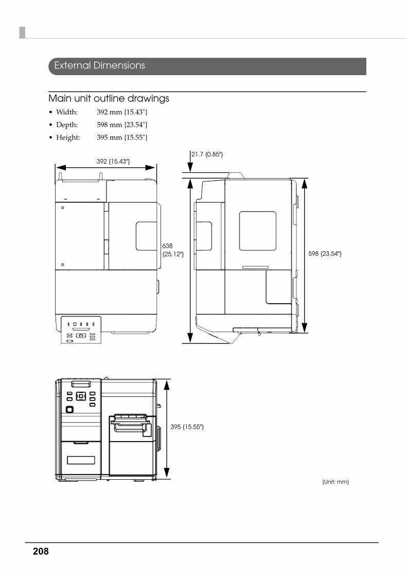
208
External Dimensions
Main unit outline drawings • Width: 392 mm {15.43"}
• Depth: 598 mm {23.54"}
• Height: 395 mm {15.55"}
[Unit: mm]
395 {15.55"}
392 {15.43"}21.7 {0.85"}
638{25.12"} 598 {23.54"}
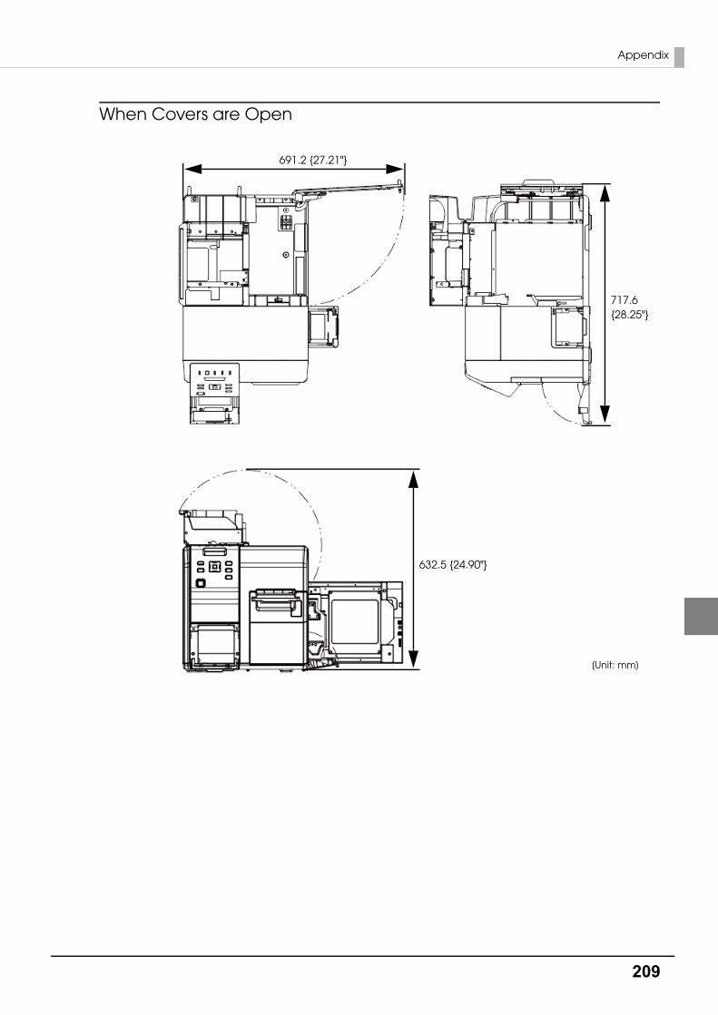
209
Appendix
When Covers are Open
[Unit: mm]
632.5 {24.90"}
691.2 {27.21"}
717.6{28.25"}
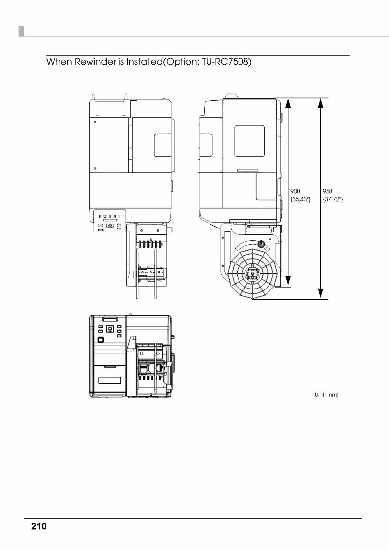
210
When Rewinder is Installed(Option: TU-RC7508)
[Unit: mm]
900{35.43"}
958{37.72"}
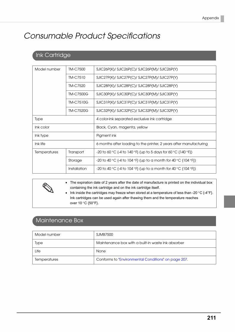
211
Appendix
Consumable Product Specifications
Ink Cartridge
Maintenance Box
Model number TM-C7500 SJIC26P(K)/ SJIC26P(C)/ SJIC26P(M)/ SJIC26P(Y)
TM-C7510 SJIC27P(K)/ SJIC27P(C)/ SJIC27P(M)/ SJIC27P(Y)
TM-C7520 SJIC28P(K)/ SJIC28P(C)/ SJIC28P(M)/ SJIC28P(Y)
TM-C7500G SJIC30P(K)/ SJIC30P(C)/ SJIC30P(M)/ SJIC30P(Y)
TM-C7510G SJIC31P(K)/ SJIC31P(C)/ SJIC31P(M)/ SJIC31P(Y)
TM-C7520G SJIC32P(K)/ SJIC32P(C)/ SJIC32P(M)/ SJIC32P(Y)
Type 4 color-ink separated exclusive ink cartridge
Ink color Black, Cyan, magenta, yellow
Ink type Pigment ink
Ink life 6 months after loading to the printer, 2 years after manufacturing
Temperatures Transport -20 to 60 C {-4 to 140 F} (up to 5 days for 60 C {140 F})
Storage -20 to 40 C {-4 to 104 F} (up to a month for 40 C {104 F})
Installation -20 to 40 C {-4 to 104 F} (up to a month for 40 C {104 F})
The expiration date of 2 years after the date of manufacture is printed on the individual box
containing the ink cartridge and on the ink cartridge itself.
Ink inside the cartridges may freeze when stored at a temperature of less than -20 C {-4°F}. Ink cartridges can be used again after thawing them and the temperature reaches over 10C {50°F}.
Model number SJMB7500
Type Maintenance box with a built-in waste ink absorber
Life None
Temperatures Conforms to "Environmental Conditions" on page 207.

212
Option Specifications
Rewinder (TU-RC7508)
The rewinder is a device used to rewind the printed paper into a roll form.
Overall dimensions (H x W x D) 293 x 222 x 403 mm {11.54 x 8.74 x 15.87"}
Weight (mass) 4.25 kg {9.37 lb}
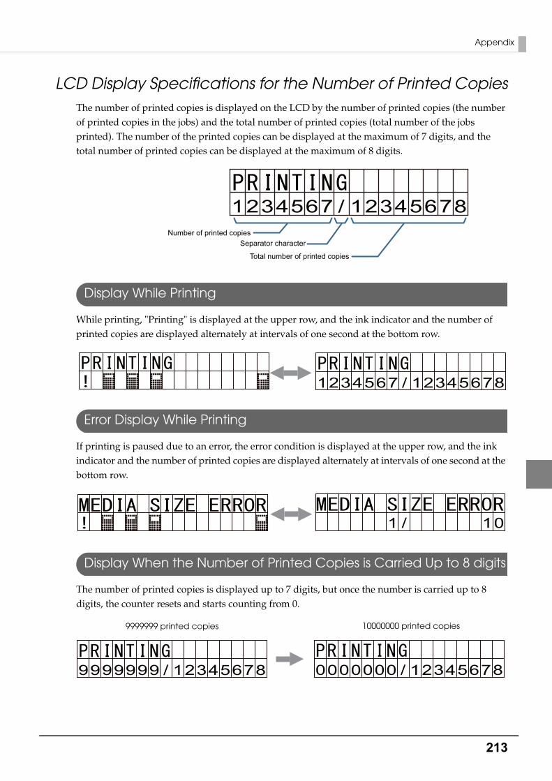
213
Appendix
LCD Display Specifications for the Number of Printed CopiesThe number of printed copies is displayed on the LCD by the number of printed copies (the number of printed copies in the jobs) and the total number of printed copies (total number of the jobs printed). The number of the printed copies can be displayed at the maximum of 7 digits, and the total number of printed copies can be displayed at the maximum of 8 digits.
Display While Printing
While printing, "Printing" is displayed at the upper row, and the ink indicator and the number of printed copies are displayed alternately at intervals of one second at the bottom row.
Error Display While Printing
If printing is paused due to an error, the error condition is displayed at the upper row, and the ink indicator and the number of printed copies are displayed alternately at intervals of one second at the bottom row.
Display When the Number of Printed Copies is Carried Up to 8 digits
The number of printed copies is displayed up to 7 digits, but once the number is carried up to 8 digits, the counter resets and starts counting from 0.
1234567 12345678/Number of printed copies
Separator character
Total number of printed copies
1234567 12345678/
1 10/
9999999 12345678/ 0000000 12345678/
9999999 printed copies 10000000 printed copies

214
Downloading Drivers, Utilities, and ManualsPrinter drivers, utilities, and manuals can be downloaded from one of the following URLs:
For customers in North America, go to the following web site:http://www.epsonexpert.com/
For customers in other countries, go to the following web site:https://download.epson-biz.com/?service=pos

215
Appendix
Media detector and paper path settings when using label printing applications
If you do not configure the media detector settings and the paper path settings correctly when using label printing applications, a media detector error or a paper path error will occur and printing will not be possible.
Here are the instructions for configuring the following label printing application.
• Changing the media detector settings in BarTender : page 216
• Changing the paper path settings in BarTender : page 218
• Changing the media detector settings in NiceLabel : page 219
• Changing the paper path settings in NiceLabel : page 221
• Changing the media detector settings in CODESOFT : page 222
• Changing the paper path settings in CODESOFT : page 223
These configuration instructions are for the following version of the label printing applica-
tion. In other versions, the functions or configuration methods may differ.
BarTender: BarTender Enterprise Automation Version 10.1 SR3
NiceLabel: NiceLabel Pro DEMO Version 6.3.1
CODESOFT: CODESOFT 2014 - Enterprise RFID Version 2014.00.00
Adjust the settings to the media you wish to use. Even if the settings of the label printing
applications and that of the device are the same, an error will occur if the media types do
not match.
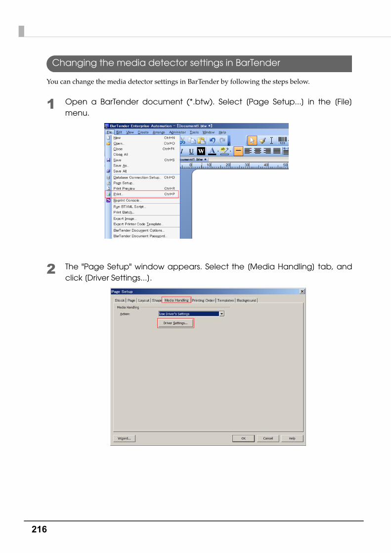
216
Changing the media detector settings in BarTender
You can change the media detector settings in BarTender by following the steps below.
1 Open a BarTender document (*.btw). Select [Page Setup...] in the [File] menu.
2 The "Page Setup" window appears. Select the [Media Handling] tab, and click [Driver Settings...].
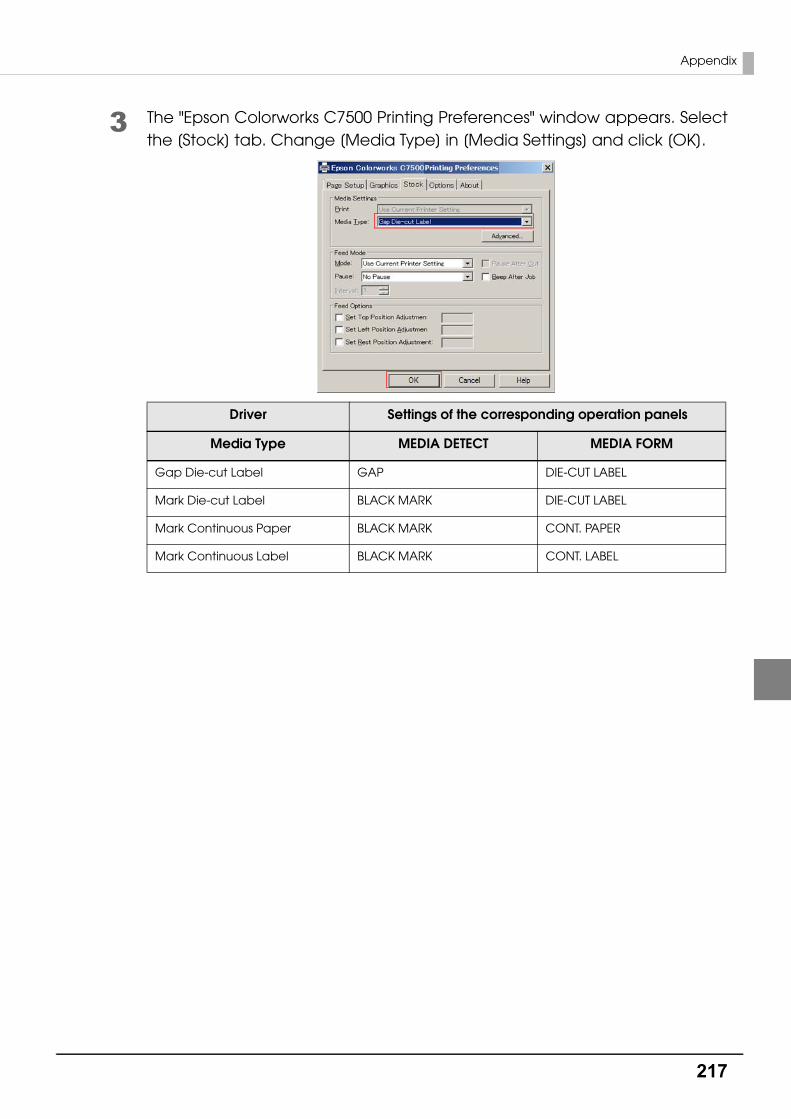
217
Appendix
3 The "Epson Colorworks C7500 Printing Preferences" window appears. Select the [Stock] tab. Change [Media Type] in [Media Settings] and click [OK].
Driver Settings of the corresponding operation panels
Media Type MEDIA DETECT MEDIA FORM
Gap Die-cut Label GAP DIE-CUT LABEL
Mark Die-cut Label BLACK MARK DIE-CUT LABEL
Mark Continuous Paper BLACK MARK CONT. PAPER
Mark Continuous Label BLACK MARK CONT. LABEL
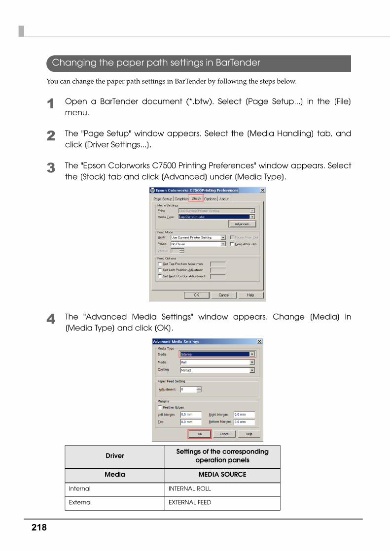
218
Changing the paper path settings in BarTender
You can change the paper path settings in BarTender by following the steps below.
1 Open a BarTender document (*.btw). Select [Page Setup...] in the [File] menu.
2 The "Page Setup" window appears. Select the [Media Handling] tab, and click [Driver Settings...].
3 The "Epson Colorworks C7500 Printing Preferences" window appears. Select the [Stock] tab and click [Advanced] under [Media Type].
4 The "Advanced Media Settings" window appears. Change [Media] in [Media Type] and click [OK].
DriverSettings of the corresponding
operation panels
Media MEDIA SOURCE
Internal INTERNAL ROLL
External EXTERNAL FEED

219
Appendix
Changing the media detector settings in NiceLabel
Change the media detector settings in NiceLabel by following the steps below.
1 Open a NiceLabel label (*.lab). Select [Label Setup...] in the [File] menu.
2 The "Label Setup Wizard" window or the "Label Setup" window appears. Select "Epson TM-C7500 for NiceLabel" and click [Properties...].
If you check the [Do not use the wizard next time] box, the "Label Setup" window appears.

220
3 The "Epson TM-C7500 for NiceLabel Printing Preferences" window appears. Change [Media type] in [Page Setup] and click [OK].
Driver Settings of the corresponding operation panels
Media type MEDIA DETECT MEDIA FORM
Labels with black mark BLACK MARK DIE-CUT LABEL
Labels with gaps GAP DIE-CUT LABEL
Continuous label with mark BLACK MARK CONT. LABEL
Continuous paper with black mark BLACK MARK CONT. PAPER
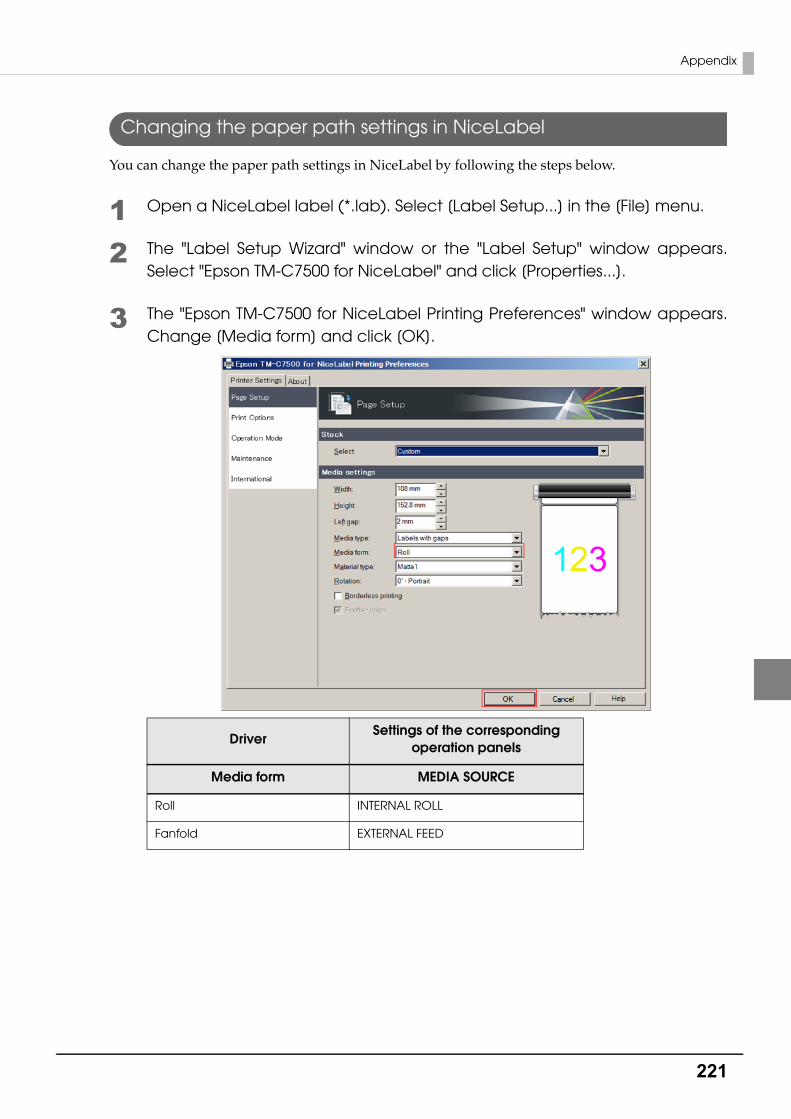
221
Appendix
Changing the paper path settings in NiceLabel
You can change the paper path settings in NiceLabel by following the steps below.
1 Open a NiceLabel label (*.lab). Select [Label Setup...] in the [File] menu.
2 The "Label Setup Wizard" window or the "Label Setup" window appears. Select "Epson TM-C7500 for NiceLabel" and click [Properties...].
3 The "Epson TM-C7500 for NiceLabel Printing Preferences" window appears. Change [Media form] and click [OK].
DriverSettings of the corresponding
operation panels
Media form MEDIA SOURCE
Roll INTERNAL ROLL
Fanfold EXTERNAL FEED
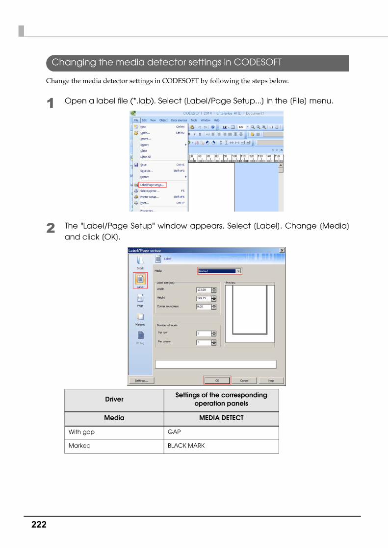
222
Changing the media detector settings in CODESOFT
Change the media detector settings in CODESOFT by following the steps below.
1 Open a label file (*.lab). Select [Label/Page Setup...] in the [File] menu.
2 The "Label/Page Setup" window appears. Select [Label]. Change [Media] and click [OK].
DriverSettings of the corresponding
operation panels
Media MEDIA DETECT
With gap GAP
Marked BLACK MARK
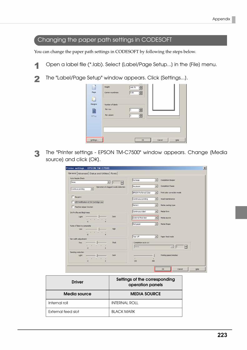
223
Appendix
Changing the paper path settings in CODESOFT
You can change the paper path settings in CODESOFT by following the steps below.
1 Open a label file (*.lab). Select [Label/Page Setup...] in the [File] menu.
2 The "Label/Page Setup" window appears. Click [Settings...].
3 The "Printer settings - EPSON TM-C7500" window appears. Change [Media source] and click [OK].
DriverSettings of the corresponding
operation panels
Media source MEDIA SOURCE
Internal roll INTERNAL ROLL
External feed slot BLACK MARK

224
For InquiriesIf you have any technical questions about this printer, or if any problems occur, please contact us with the following information.
❏ Type of inquiry: Problem / Question
❏ Date:
❏ Your company:
❏ Department:
❏ Your name:
❏ Phone/Fax/Email:
❏ Computer information:
• Manufacturer / CPU
❏ OS (with Service Pack information):
❏ Model name of the printer:
❏ Printer driver: Installed / Not installed
❏ Connection type: USB / Ethernet / MS shared (Client / Server)
❏ Install protocol/service: NetBEUI / NetWare Client (Novell (Ver. )) / Microsoft (Ver. )) / TCPIP / SNMP agent / Other
❏ Print tool: Local (USB) / Standard TCPIP / OS attached LPR/ Epson TCPIP Print (Name) / Own custom application/ Other (Product name/Ver.)
❏ Firewall: OS standard / Personal (Product name/Ver.) / None
❏ Your application information:
• Windows service operation / Normal EXE operation
❏ EPSON application status: EpsonNet Simple Viewer / EPSON Monitoring Tool // EpsonNet SDK for Windows / Printer Setting / Other (Application name)
❏ Phenomenon of the problem (or content of the question):
❏ System configuration: Hardware configuration such as computer and network, and Software module configuration
❏ Procedure of reproduction of the problem: Operation procedure, functional procedure, function and argument value to reproduce
❏ Reproducibility of the problem: Yes ( out of times) / No
Contents of technical questions must be about our printers only. For those about products of
Microsoft Corporation or other companies, please contact them.
If any problems occur, check whether there is any physical cause (such as connection or
power problems) before contacting us.


