129-01/629-01
Distributed By: M&M Control Service, INC.
Phone: 800-876-0036 Fax: 847-356-0747 Email: [email protected]
Distributed By: M&M Control Service, Inc. http://www.mmcontrol.com/claval-index.php 800-876-0036 847-356-0566

Distributed By: M&M Control Service, Inc. http://www.mmcontrol.com/claval-index.php 800-876-0036 847-356-0566

Distributed By: M&M Control Service, Inc. http://www.mmcontrol.com/claval-index.php 800-876-0036 847-356-0566
Distributed By: M&M Control Service, Inc. http://www.mmcontrol.com/claval-index.php 800-876-0036 847-356-0566

Note: We recommend protecting tubing andvalve from freezing temperatures.
IndependentOperatingPressure
CLA-VAL129-01/629-01
Float Valve
CFM2Float Control
FilterIsolationValves
Raw WaterInlet
CLA-VAL 49-01/649-01Rate-of Flow Controller
IsolationValves
TANKCLA-VAL
129-01/629-01
Control Piping(Not Furnished)
Float Control
4
32D1
Y
B
F
INDEPENDENTOPERATINGPRESSURE
INLET OUTLET
A1
D3
D2
C
B
S
MODEL
Float Valve
Typical Applications
Piping and Tank SizingInstall valve and control as shown in the diagram above. Thefloat control should be located in a still liquid surface. If it isnecessary to obtain this condition, a stilling well should beconstructed. Mount the control on the connecting piping withthe outlet port at the desired high water level.
Filter Liquid Level ControlMaintains constant level in rapid sand filter.Usually requires the use of an independentoperating pressure as shown.
Schematic Diagram
Item Description1 Hytrol (Main Valve)2 X47A Ejector3 Bell Reducer4 CFM2 Float Control
Optional Features
Item DescriptionA X46A Flow Cleaner StrainerB CK2 (Isolation Valve)C CV Flow Control (Closing)D Check Valves With Isolation ValveF Independent Operating PressureS CV Flow Control (Opening)Y X43 "Y" Strainer
• Accurate and Repeatable Level Control• Proportional Flow• Reliable Hydraulic Operation• Drip Tight Positive Shut-off• Completely Automatic Operation
The Cla-Val Model 129-01/629-01 Float Valve maintains a relativelyconstant level in storage tanks and reservoirs by admitting flow intothe tank in direct proportion to the flow out of the tank. It is ahydraulically operated, pilot controlled, diaphragm valve. The rotarydisc type float operated pilot control is installed at the high liquid levelin the reservoir and is connected via tubing or pipe to the main valve.As the liquid level changes, the float control proportionally opens orcloses the main valve, keeping the liquid level nearly constant. If thecheck feature option is added and a pressure reversal occurs, thedownstream pressure is admitted into the main valve cover chamberand the valve closes to prevent return flow.
✣
The "D" feature on a vertically installed 6" andlarger valve must be horizontally installed.
129-01629-01
TM
TM
Distributed By: M&M Control Service, Inc. http://www.mmcontrol.com/claval-index.php 800-876-0036 847-356-0566

*11⁄2" Size Only
VALVE SIZE (Inches) 11⁄4 -11⁄2 2 2 1⁄2 3 4 6 8 10 12 14 16A Threaded 7.25 9.38 11.00 12.50 — — — — — — —AA 150 ANSI 8.50* 9.38 11.00 12.00 15.00 20.00 25.38 29.75 34.00 39.00 41.38AAA 300 ANSI 9.00* 10.00 11.62 13.25 15.62 21.00 26.38 31.12 35.50 40.50 43.50B DIA. 5.62 6.62 8.00 9.12 11.50 15.75 20.00 23.62 28.00 32.75 35.50C MAX.. 5.50 6.50 7.56 8.19 10.62 13.38 16.00 17.12 20.88 24.19 25.00D Threaded 3.25 4.75 5.50 6.25 — — — — — — —DD 150 ANSI 4.00* 4.75 5.50 6.00 7.50 10.00 12.75 14.88 17.00 19.50 20.81DDD 300 ANSI 4.25* 5.00 5.88 6.38 7.88 10.50 13.25 15.56 17.75 20.25 21.62E 1.12 1.50 1.69 2.56 3.19 4.31 5.31 9.25 10.75 12.62 15.50F 150 ANSI 2.50 3.00 3.50 3.75 4.50 5.50 6.75 8.00 9.50 10.50 11.75FF 300 ANSI 3.06 3.25 3.75 4.13 5.00 6.25 7.50 8.75 10.25 11.50 12.75G Threaded 1.88 3.25 4.00 4.50 — — — — — — —GG 150 ANSI 4.00* 3.25 4.00 4.00 5.00 6.00 8.00 8.62 13.75 14.88 15.69GGG 300 ANSI 4.25* 3.50 4.31 4.38 5.31 6.50 8.50 9.31 14.50 15.62 16.50H NPT Body Tapping 3⁄8 3⁄8 1⁄2 1⁄2 3⁄4 3⁄4 1 1 1 1 1J NPT Cover Center Plug 1⁄4 1⁄2 1⁄2 1⁄2 3⁄4 3⁄4 1 1 11⁄4 1 1⁄2 2K NPT Cover Tapping 3⁄8 3⁄8 1⁄2 1⁄2 3⁄4 3⁄4 1 1 1 1 1Valve Stem InternalThread UNF 10-32 10-32 10-32 1⁄4-28 1⁄4-28 3⁄8-24 3⁄8-24 3⁄8-24 3⁄8-24 3⁄8-24 1⁄2-20Stem Travel 0.4 0.6 0.7 0.8 1.1 1.7 2.3 2.8 3.4 4.0 4.5
Approx.Ship Wt. Lbs. 15 35 50 70 140 285 500 780 1165 1600 2265
OUTLET
A
AA
AAA
E
INLET
H
JB (DIAMETER)
K
FF F
DDD
DDINLET
OUTLET
C
H
B (DIAMETER)
K
GGGGG G
C
D
J
4" Globe, Flanged
4" Angle, Flanged
Component Material Options
Body & Cover Ductile Cast Bronze Stainless AluminumIron Steel Steel
Available Sizes 11⁄4" - 16" 11⁄4" - 16" 11⁄4" - 16" 11⁄4" - 16" 11⁄4" - 16"
Disc Retainer & Cast Cast Bronze Stainless AluminumDiaphragm Washer Iron Steel Steel
Trim: Disc Guide, Bronze is standard.Seat & Cover Bearing Stainless Steel is optional. Stainless Steel is standard.
Disc Buna-N® Rubber
Diaphragm Nylon Reinforced Buna-N® Rubber
Stem, Nut & Spring Stainless Steel
Materials
Model 129-01 Dimensions (In inches)
100-01 (Globe) 100-01 (Angle)
Model 129-01 (Uses Basic Valve Model 100-01)
ANSIGrade Material Standards* 150 lb. 300 lb.
ASTM A536 Ductile Iron B16.42 250 400 400ASTM A216-WCB Cast Steel B16.5 285 400 400
ASTM B62 Bronze B16.24 225 400 400
ASTM A743 Stainless Steel B16.5 285 400 400356-T6 Aluminum B16.1 275 — —
Note:
Threaded
*ANSI standards are for flange dimensions only.Flanged valves are available faced but not drilled.
** End Details machined to ANSI B2.1 specifications.
Pressure Ratings (Recommended Maximum Pressure - psi)
Pressure Class
FlangedValve Body & Cover
End**Details
2" Globe, Threaded
Distributed By: M&M Control Service, Inc. http://www.mmcontrol.com/claval-index.php 800-876-0036 847-356-0566

Component Material Options
Body & Cover Ductile Cast Bronze Stainless AluminumIron Steel Steel
Available Sizes 3"-30" 3"-30" 3"-16" 3"-16" 3"-16"
Disc Retainer & Cast Cast Bronze Stainless AluminumDiaphragm Washer Iron Steel Steel
Trim: Disc Guide, Bronze is standard.Seat & Cover Bearing Stainless Steel is optional. Stainless Steel is standard.
Disc Buna-N® Rubber
Diaphragm Nylon Reinforced Buna-N® Rubber
Stem, Nut & Spring Stainless Steel
B (DIAMETER)
H
INLET
G
A
AA
J
C
OUTLET
F FF
3" Globe, Flanged
6" Angle, Flanged
Model 629-01 (Uses Basic Valve Model 100-20)
Materials
ANSIGrade Material Standards* 150 lb. 300 lb.
ASTM A-\536 Ductile Iron B16.42 250 400
ASTM A216-WCB Cast Steel B16.5 285 400
ASTM B62 Bronze B16.24 225 400
ASTM A743 Stainless Steel B16.5 285 400
356-T6 Aluminum B16.1 275 —
Note: *ANSI standards are for flange dimensions only.Flanged valves are available faced but not drilled.
Pressure Ratings (Recommended Maximum Pressure - psi)
Pressure Class
FlangedValve Body & Cover
H
B(DIAMETER)
J
C
OUTLET
E EE
INLET
DDD
G
100-20 (Angle)100-20 (Globe)
Model 629-01 Dimensions (In inches)
6" Globe, Flanged
VALVE SIZE (Inches) 3 4 6 8 10 12 14 16 18 20 24 30A 150 ANSI 10.25 13.88 17.75 21.38 26.00 30.00 34.25 35.00 42.12 48.00 48.00 63.25AA 300 ANSI 11.00 14.50 18.62 22.38 27.38 31.50 — 36.62 43.63 49.62 49.75 —B DIA. 6.62 9.12 11.50 15.75 20.00 23.62 28.00 28.00 35.44 35.44 35.44 53.19C MAX. 7.00 8.62 11.62 15.00 17.88 21.00 20.88 25.75 25.00 31.00 31.00 43.94D 150 ANSI — 6.94 8.88 10.69 — — — — — — — —DD 300 ANSI — 7.25 9.38 11.19 — — — — — — — —E 150 ANSI — 5.50 6.75 7.25 — — — — — — — —EE 300 ANSI — 5.81 7.25 7.75 — — — — — — — —F 150 ANSI 3.75 4.50 5.50 6.75 8.00 9.50 11.00 11.75 15.88 14.56 17.00 19.88FF 300 ANSI 4.12 5.00 6.25 7.50 8.75 10.25 — 12.75 15.88 16.06 19.00 —G NPT Body Tapping 3⁄8 1⁄2 3⁄4 3⁄4 1 1 1 1 1 1 1 1H NPT Cover Center Plug 1⁄2 1⁄2 3⁄4 3⁄4 1 1 11⁄4 11⁄4 2 2 2 2J NPT Cover Tapping 3⁄8 1⁄2 3⁄4 3⁄4 1 1 1 1 1 1 1 1Valve Stem InternalThread UNF 10-32 1⁄4 -28 1⁄4 -28 3⁄8 -24 3⁄8 -24 3⁄8 -24 3⁄8 -24 3⁄8 -24 1⁄2 -20 1⁄2 -20 1⁄2 -20 3⁄4 -16Stem Travel 0.6 0.8 1.1 1.7 2.3 2.8 3.4 3.4 4.5 4.5 4.5 6.5Approx Ship Wt. Lbs. 45 85 195 330 625 900 1250 1380 2733 2551 2733 6500
Distributed By: M&M Control Service, Inc. http://www.mmcontrol.com/claval-index.php 800-876-0036 847-356-0566

Pressure Ratings Maximum: 300 psi
Temperature RangeWater: to 180°F
MaterialsPilot Control System:
Cast Bronze ASTM B-62 with303 Stainless Steel Trim, Bronze fittings and copper tubing.
Optional Materials Aluminum, Bronze and Stainless Steel available at extra cost.
Control Piping (customer supplied)Use either copper tubing or brass pipe between CFM2 Float Control and the main valve pilot system.1/2" dia. for distances less than 25 feet;3/4" dia. for greater distances.
When Ordering, Please Specify1. Catalog No. 129-01 or No. 629-012. Valve Size3. Pattern - Globe or Angle4. Pressure Class5. Threaded or Flanged6. Materials Desired7. Desired Options8. When Vertically Installed
X Max. 5.50 5.75 7.25 8.00 9.50 12.25 14.50 17.00 26.00 29.00 39.00 39.00 42.00 50.00 50.00
Y Max. 4.00 4.00 4.50 5.00 6.00 8.00 10.25 12.00 14.25 16.75 18.00 18.00 18.00 30.00 30.00
Z Max. 4.00 4.00 4.50 5.00 6.00 8.00 10.25 12.00 14.25 16.75 18.00 18.00 18.00 30.00 30.00
Pilot System Dimensions (In Inches)
Y
Z
XY
Z
X
GLOBE
Inlet
Inlet
CFM2 FLOATCONTROL
ANGLE
We recommend providing adequate space around valve for maintenance work
Pilot System Specifications
VALVE SIZE 11⁄4 & 11⁄2" 2" 21⁄2" 3" 4" 6" 8" 10" 12" 14" 16" 18" 20" 24" 30"
30… Max. Ball Travel Up(Closed)
30… Max. Ball Travel D(Open)
InletSupply1/2" NPTFrom ValvePilot Systems
1.50
.94
8.00 .06Standard
—+
4" DIA.
Important Notice: Do Not Oversize
CLA-VALPO Box 1325 Newport Beach CA 92659-0325Phone: 949-722-4800 Fax: 949-548-5441
CLA-VAL CANADA CLA-VAL EUROPE4687 Christie DriveBeamsville, OntarioCanada LOR 1B4Phone: 905-563-4963Fax: 905-563-4040
Chemin des Mésanges 1CH-1032 Romanel/Lausanne, SwitzerlandPhone: 41-21-643-15-55Fax: 41-21-643-15-50
'COPYRIGHT CLA-VAL 2004 Printed in USASpecifications subject to change without notice. www.cla-val.comE-129-01/629-01 (R-7/04)
TM
Represented By:
These Symbols A and B Indicate Available Sizes
Globe
Angle
Normal Continuous
Normal Continuous
Inches
mm
End Detail
Model129-01
Basic Valve100-01
Suggested Flow(GPM)
Suggested Flow(Liters/sec)
Model629-01
Globe
Angle
Normal Continuous
Normal Continuous
Basic Valve100-20
Suggested Flow(GPM)
Suggested Flow(Liters/sec)
✣ 629-01 is the reduced internal port size version of the 129-01.For 100-01 basic valves suggested flow calculations were based on flow through Schedule 40 Pipe. Normal continuous flow is approx. 20 ft/sec (6.1 meters/sec) .For 100-20 basic valves suggested flow calculations were based on flow through the valve seat. Approx. 26 ft/sec (7.9 meters/sec) is used for normal continuous flow.Normal continuous flow through the valve seat for the 30” 100-20 is approx. 20 ft/sec (6.1 meters/sec).
580
37
1025
65
2300
145
4100
258
6400
403
9230
581
9230
581
16500
1040
16500
1040
16500
1040
28000
1764
260
16
A** A A A A A A A A A A A
B B B
4
100
6
150
8
200
10
250
12
300
14
350
16
400
18
450
20
500
24
600
30
750
3
80
800
50
1800
113
3100
195
4900
309
7000
441
8400
529
11000
693
460
29
A A A A A A A A
B
2 1/2
65
300
19
A
B
2
50
210
13
A
B
1 1/2
40
125
8
A
B
1 1/4
32
93
6
A
B B B B B B B
Threaded & Flanged Flanged
Valve Selection
Threaded
**Flanged End Detail Only
Distributed By:
M&M Control Service, INC.
Phone: 800-876-0036
Fax: 847-356-0747
Email: [email protected]
Distributed By: M&M Control Service, Inc. http://www.mmcontrol.com/claval-index.php 800-876-0036 847-356-0566

DescriptionThe CIa-VaI Model 100-01 Hytrol Valve is a main valve forCIa-VaI Automatic Control Valves. It is a hydraulically operated,diaphragm-actuated, globe or angle pattern valve.
This valve consists of three major components; body, diaphragmassembly, and cover.The diaphragm assembly is the only mov-ing part. The diaphragm assembly uses a diaphragm of nylon fab-ric bonded with synthetic rubber. A synthetic rubber disc, con-tained on three and one half sides by a disc retainer and discguide, forms a seal with the valve seat when pressure is appliedabove the diaphragm. The diaphragm assembly forms a sealedchamber in the upper portion of the valve, separating operatingpressure from line pressure.
Installation
1. Before valve is installed, pipe lines should be flushed of allchips, scale and foreign matter.2. It is recommended that either gate or block valves be installedon both ends of the 100-01 Hytrol Valve to facilitate isoIating thevalve for preventive maintenance and repairs.3. Place the valve in the line with flow through the valve in thedirection indicated on the inlet nameplate. (See “Flow Direction”Section)4. Allow sufficient room around valve to make adjustments andfor disassembly.5. CIa-VaI 100-01 Hytrol Valves operate with maximum efficiencywhen mounted in horizontal piping with the cover UP, however,
other positions are acceptable. Due to size and weight of thecover and internal components of 8 inch and �larger valves,installation with the cover UP is advisable. This makes internalparts readily accessible for periodic inspection.6. If a pilot control system is installed on the 100-01 Hytrol Valve,use care to prevent damage. If it is necessary to remove fittingsor components, be sure they are kept clean and replacedexactly as they were.7. After the valve is installed and the system is first pressurized,vent air from the cover chamber and pilot system tubing byloosening fittings at all high points.
Tight Closing OperationWhen pressure from the valve inlet (oran equivalent independent operatingpressure) is applied to the diaphragmchamber the valve closes drip-tight.
Full Open OperationWhen pressure in diaphragm chamberis relieved to a zone of lower pressure(usually atmosphere) the line pressure(5 psi Min.) at the valve inlet opens thevalve.
Modulating ActionValve modulates when diaphragm pres-sure is held at an intermediate pointbetween inlet and discharge pressure.With the use of a Cla-Val. "modulatingcontrol," which reacts to line pressurechanges, the pressure above thediaphragm is varied, allowing the valveto throttle and compensate for thechange.
Principles of Operation
Three Way Pilot Control
Three Way Pilot Control
RestrictionModulating
Control
100-01Hytrol Valve
MODEL
INSTALLATION / OPERATION / MAINTENANCE
Distributed By: M&M Control Service, Inc. http://www.mmcontrol.com/claval-index.php 800-876-0036 847-356-0566

Flow DirectionThe flow through the 100-01 Hytrol Valve can be in one of twodirections. When flow is “up-and-over the seat,” it is in “normal”flow and the valve will fail in the open position. When flow is “over-the seat-and down,” it is in “reverse” flow and the valve will fail inthe closed position. There are no permanent flow arrow markings.The valve must be installed according to nameplate data.
BRIDGEWALL INDlCATOR
Normal Flow Reverse Flow
TroubleshootingThe following troubleshooting information deals strictly with theModel 100-01 Hytrol Valve. This assumes that all other compo-nents of the pilot control system have been checked out and arein proper working condition. (See appropriate sections inTechnical Manual for complete valve).
Three ChecksThe 100-01 Hytrol Valve has only one moving part (the diaphragmand disc assembly). So, there are only three major types of prob-lems to be considered.
First: Valve is stuck - that is, the diaphragm assembly is not freeto move through a full stroke either from open to close or viceversa.
Second: Valve is free to move and can’t close because of a wornout diaphragm.
Third: Valve leaks even though it is free to move and thediaphragm isn’t leaking.
Closed isolation valves in control system, or in main line.
Lack of cover chamber pressure.
Diaphragm damaged. (See Diaphragm Check.)
Diaphragm assembly inoperative.Corrosion or excessive scale build up on valve stem.(See Freedom of Movement Check)
Mechanical obstruction. Object lodged in valve.(See Freedom of Movement Check)
Worn disc. (See Tight Sealing Check)
Badly scored seat. (See Tight Sealing Check)
Closed upstream and/or downstream isolation valves in main line.
Insufficient line pressure.
Diaphragm assembly inoperative. Corrosion or excessivebuildup on valve stem. (See Freedom of Movement Check)
Diaphragm damaged. (For valves in "reverse flow" only)
After checking out probable causes and remedies, the following three checks can be used to diagnose the nature of theproblem before maintenance is started. They must be done in the order shown.
Open Isolation valves.
Check upstream pressure, pilot system, strainer, tubing, valves, or needlevalves for obstruction.
Replace diaphragm.
Clean and polish stem. Inspect and replace any damaged or badly erodedpart.
Remove obstruction.
Replace disc.
Replace seat.
Open isolation valves.
Check upstream pressure. (Minimum 5 psi flowing line pressure differential.)
Clean and polish stem. Inspect and replace anydamaged or badly eroded part.
Replace diaphragm.
Fails to Close
Fails to Open
CAUTION:Care should be taken when doing the troubleshooting checks onthe 100-01 Hytrol Valve. These checks do require the valve toopen fully.This will either allow a high flow rate through the valve,or the downstream pressure will quickly increase to the inletpressure. In some cases, this can be very harmful. Where this isthe case, and there are no block valves in the system to protectthe downstream piping, it should be realized that the valve can-not be serviced under pressure. Steps should be taken toremedy this situation before proceeding any further.
(cast into side of valve body)
SYMPTOM PROBABLE CAUSE REMEDY
Recommended Tools1. Three pressure gauges with ranges suitable to the instal-lation to be put at Hytrol inlet, outlet and cover connections.
2. Cla-Val Model X101 Valve Position Indicator. This pro-vides visual indication of valve position without disassemblyof valve.
3. Other items are: suitable hand tools such as screw-drivers, wrenches, etc. soft jawed (brass or aluminum) vise,400 grit wet or dry sandpaper and water for cleaning.
All trouble shooting is possible without removing the valve from theline or removing the cover. It is highly recommended to permanentlyinstall a Model X101 Valve Position Indicator and three gauges inunused Hytrol inlet, outlet and cover connections.
2
Distributed By: M&M Control Service, Inc. http://www.mmcontrol.com/claval-index.php 800-876-0036 847-356-0566
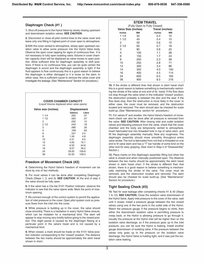
Diaphragm Check (#1 )1. Shut off pressure to the Hytrol Valve by slowly closing upstreamand downstream isolation valves. SEE CAUTION.
2. Disconnect or close all pilot control lines to the valve cover andleave only one fitting in highest point of cover open to atmosphere.
3.With the cover vented to atmosphere, slowly open upstream iso-lation valve to allow some pressure into the Hytrol Valve body.Observe the open cover tapping for signs of continuous flow. It isnot necessary to fully open isolating valve. Volume in cover cham-ber capacity chart will be displaced as valve moves to open posi-tion. Allow sufficient time for diaphragm assembly to shift posi-tions. If there is no continuous flow, you can be quite certain thediaphragm is sound and the diaphragm assembly is tight. If thefluid appears to flow continuously this is a good reason to believethe diaphragm is either damaged or it is loose on the stem. Ineither case, this is sufficient cause to remove the valve cover andinvestigate the leakage. (See “Maintenance” Section for procedure.)
Freedom of Movement Check (#2)4. Determining the Hytrol Valve’s freedom of movement can bedone by one of two methods.
5. For most valves it can be done after completing DiaphragmCheck (Steps 1, 2, and 3). SEE CAUTION. At the end of step 3the valve should be fully open.
6. If the valve has a Cla-Val X101 Position Indicator, observe theindicator to see that the valve opens wide. Mark the point of max-imum opening.
7. Re-connect enough of the control system to permit the applica-tion of inlet pressure to the cover. Open pilot system cock so pres-sure flows from the inlet into the cover.
8. While pressure is building up in the cover, the valve shouldclose smoothly. There is a hesitation in every Hytrol Valve closure,which can be mistaken for a mechanical bind. The stem willappear to stop moving very briefly before going to the closed posi-tion. This slight pause is caused by the diaphragm flexing at aparticular point in the valve’s travel and is not caused by amechanical bind.
9. When closed, a mark should be made on the X101 Valve posi-tion indicator corresponding to the “closed” position. The distancebetween the two marks should be approximately the stem travelshown in chart.
10. If the stroke is different than that shown in stem travel chartthis is a good reason to believe something is mechanically restrict-ing the stroke of the valve at one end of its travel. If the flow doesnot stop through the valve when in the indicated “closed” position,the obstruction probably is between the disc and the seat. If theflow does stop, then the obstruction is more likely in the cover. Ineither case, the cover must be removed, and the obstructionlocated and removed. The stem should also be checked for scalebuild-up. (See “Maintenance, section for procedure.)
11. For valves 6” and smaller, the Hytrol Valve’s freedom of move-ment check can also be done after all pressure is removed fromthe valve. SEE CAUTION. After closing inlet and outlet isolationvalves and bleeding pressure from the valve, check that the coverchamber and the body are temporarily vented to atmosphere.Insert fabricated tool into threaded hole in top of valve stem, andlift the diaphragm assembly manually. Note any roughness. Thediaphragm assembly should move smoothly throughout entirevalve stroke.The tool is fabricated from rod that is threaded on oneend to fit valve stem and has a “T” bar handle of some kind on theother end for easy gripping. (See chart in Step 4 of “Disassembly”Section.)
12. Place marks on this diaphragm assembly lifting tool when thevalve is closed and when manually positioned open. The distancebetween the two marks should be approximately the stem travelshown in stem travel chart. If the stroke is different than thatshown, there is a good reason to believe something is mechani-cally restricting the stroke of the valve. The cover must beremoved, and the obstruction located and removed. The stemshould also be checked for scale build-up. (See “Maintenance”Section for procedure.)
Tight Sealing Check (#3)13. Test for seat leakage after completing checks #1 & #2 (Steps1 to 12). SEE CAUTION. Close the isolation valve downstream ofthe Hytrol Valve. Apply inlet pressure to the cover of the valve, waituntil it closes. Install a pressure gauge between the two closedvalves using one of the two ports in the outlet side of the Hytrol.Watch the pressure gauge. If the pressure begins to climb, theneither the downstream isolation valve is permitting pressure tocreep back, or the Hytrol is allowing pressure to go through it.Usually the pressure at the Hytrol inlet will be higher than on theisolation valve discharge, so if the pressure goes up to the inletpressure, you can be sure the Hytrol is leaking. Install anothergauge downstream of isolating valve. If the pressure between thevalves only goes up to the pressure on the isolation valvedischarge, the Hytrol Valve is holding tight, and it was just the iso-lation valve leaking.
STEM TRAVEL(Fully Open to Fully Closed)
Valve Size (inches) Travel (inches)Inches MM Inches MM
1 1/4 32 0.4 101 1/2 40 0.4 102 50 0.6 152 1/2 65 0.7 183 80 0.8 204 100 1.1 286 150 1.7 438 200 2.3 5810 250 2.8 7112 300 3.4 8614 350 4.0 10016 400 4.5 11424 600 6.5 16536 900 8.5 216
COVER CHAMBER CAPACITY(Liquid Volume displaced when valve opens)
Valve size (inches) DisplacementGallons Liters
1 1/4 .020 .071 1/2 .020 .072 .032 .122 1/2 .043 .163 .080 .304 .169 .646 .531 2.08 1.26 4.810 2.51 9.512 4.00 15.114 6.50 24.616 9.57 36.224 29.00 109.836 42.00 159.0
3
Distributed By: M&M Control Service, Inc. http://www.mmcontrol.com/claval-index.php 800-876-0036 847-356-0566

Maintenance
Preventative MaintenanceThe Cla-Val Co. Model 100-01 Hytrol Valve requires no lubricationor packing and a minimum of maintenance. However, a periodicinspection schedule should be established to determine how theoperating conditions of the system are affecting the valve. Theeffect of these actions must be determined by inspection.
DisassemblyInspection or maintenance can be accomplished without remov-ing the valve from the line. Repair kits with new diaphragm anddisc are recommended to be on hand before work begins.
WARNING: Maintenance personnel can be injured and equip-ment damaged if disassembly is attempted with pressure in thevalve. SEE CAUTION.
1. Close upstream and downstream isolation valves and inde-pendent operating pressure when used to shut off all pressureto the valve.
2. Loosen tube fittings in the pilot system to remove pressure fromvalve body and cover chamber. After pressure has been releasedfrom the valve, use care to remove the controls and tubing. Noteand sketch position of tubing and controls for re-assembly. Theschematic in front of the Technical Manual can be used as a guidewhen reassembling pilot system.
3. Remove cover nuts and remove cover. If the valve has been inservice for any length of time, chances are the cover will have tobe loosened by driving upward along the edge of the cover with adull cold chisel.
On 6” and smaller valves block and tackle or a power hoist can beused to lift valve cover by inserting proper size eye bolt in place ofthe center cover plug. on 8” and larger valves there are 4 holes(5/8” — 11 size) where jacking screws and/or eye bolts may beinserted for lifting purposes. Pull cover straight up to keep fromdamaging the integral seat bearing and stem.
4. Remove the diaphragm and disc assembly from the valve body.With smaller valves this can be accomplished by hand by pullingstraight up on the stem so as not to damage the seat bearing.On large valves, an eye bolt of proper size can be installed in thestem and the diaphragm assembly can be then lifted with a blockand tackle or power hoist. Take care not to damage the stem orbearings. The valve won't work if these are damaged.
5. The next item to remove is the stem nut. Examine the stemthreads above the nut for signs of mineral deposits or corrosion. Ifthe threads are not clean, use a wire brush to remove as much ofthe residue as possible. Attach a good fitting wrench to the nutand give it a sharp “rap” rather than a steady pull. Usually sev-eral blows are sufficient to loosen the nut for further removal. Onthe smaller valves, the entire diaphragm assembly can be held bythe stem in a vise equipped with soft brass jaws before remov-ing the stem nut.
The use of a pipe wrench or a vise without soft brass jaws scarsthe fine finish on the stem. No amount of careful dressing canrestore the stem to its original condition. Damage to the finish ofthe stem can cause the stem to bind in the bearings and the valvewill not open or close.
6. After the stem nut has been removed, the diaphragm assemblybreaks down into its component parts. Removal of the disc fromthe disc retainer can be a problem if the valve has been in serv-ice for a long time. Using two screwdrivers inserted along the out-side edge of the disc usually will accomplish its removal. Careshould be taken to preserve the spacer washers in water, partic-ularly if no new ones are available for re-assembly.
7. The only part left in the valve body is the seat which ordinarilydoes not require removal. Careful cleaning and polishing of insideand outside surfaces with 400 wet/dry sandpaper will usuallyrestore the seat’s sharp edge. If, however, it is badly worn andreplacement is necessary, it can be easily removed.
Seats in valve sizes 1 1/4” through 6” are threaded into the valvebody. They can be removed with accessory X109 Seat RemovingTool available from the factory. On 8” and larger valves, the seat isheld in place by flat head machine screws. Use a tight-fitting, longshank screwdriver to prevent damage to seat screws. If uponremoval of the screws the seat cannot be lifted out, it will be nec-essary to use a piece of angle or channel iron with a hole drilledin the center. Place it across the body so a long stud can be insert-ed through the center hole in the seat and the hole in the angleiron. By tightening the nut a uniform upward force is exerted on theseat for removal.
NOTE: Do not lift up on the end of the angle iron as this may forcethe integral bearing out of alignment, causing the stem to bind.
VALVE STEM THREAD SIZEValve Size Thread Size (UNF Internal)
1 1/4"—2 1/2" 10—323"—4" 1/4—286"—14" 3/8—24
16" 1/2—2024" 3/4-1636” 3/4-16
COVER CENTER PLUG SIZEValve Size Thread Size (NPT)
1 1/4"—1 1/2" 1/4"2"—3" 1/2"4"—6" 3/4"8"—10" 1"
12" 1 1/4"14" 1 1/2"16" 2"24" 2"36” 2”
VALVE COVER
DULL COLD CHISEL(ANGLE UPWARD AS MUCHAS POSSIBLE)
HAMMER
NUT
ANGLE OR CHANNEL IRON
LONG STUD OR BOLT
NUT OR BOLT HEAD
DO NOTLIFT
VALVE SEAT
VALVE BODY
4
Distributed By: M&M Control Service, Inc. http://www.mmcontrol.com/claval-index.php 800-876-0036 847-356-0566

Lime Deposits
One of the easiest ways to remove lime deposits from the valvestem or other metal parts is to dip them in a 5-percent muriaticacid solution just long enough for the deposit to dissolve.This willremove most of the common types of deposits. CAUTlON: USEEXTREME CARE WHEN HANDLING ACID. Rinse parts inwater before handling. If the deposit is not removed by acid, thena fine grit (400) wet or dry sandpaper can be used with water.
Reassembly
1. Reassembly is the reverse of the disassembly procedure. If anew disc has been installed, it may require a different number ofspacer washers to obtain the right amount of “grip” on the disc.When the diaphragm assembly has been tightened to a pointwhere the diaphragm cannot be twisted, the disc should be com-pressed very slightly by the disc guide. Excessive compressionshould be avoided. Use just enough spacer washers to hold thedisc firmly without noticeable compression.
2. MAKE SURE THE STEM NUT IS VERY TIGHT. Attach a goodfitting wrench to the nut and give it a sharp “rap” rather than asteady pull. Usually several blows are sufficient to tighten thestem nut for final tightening. Failure to do so could allow thediaphragm to pull loose and tear when subjected to pressure.
Test Procedure After Valve Assembly
There are a few simple tests which can be made in the field tomake sure the Hytrol Valve has been assembled properly. Dothese before installing pilot system and returning valve toservice. These are similar to the three troubleshooting tests.
1. Check the diaphragm assembly for freedom of movement afterall pressure is removed from the valve. SEE CAUTlON. Insertfabricated tool into threaded hole in top of valve stem, and lift thediaphragm assembly manually. Note any roughness, sticking orgrabbing. The diaphragm assembly should move smoothlythroughout entire valve stroke.The tool is fabricated from rod thatis threaded on one end to fit valve stem (See chart in Step 4 of“Disassembly” section.) and has a “T” Bar handle of some kindon the other end for easy gripping.
Place marks on this diaphragm assembly lifting tool when thevalve is closed and when manually positioned open. The dis-tance between the two marks should be approximately the stemtravel shown in stem travel chart. (See “Freedom of MovementCheck” section.) If the stroke is different than that shown, thereis a good reason to believe something is mechanically restrictingthe stroke of the valve. The cover must be removed, the obstruc-tion located and removed. (See “Maintenance” Section forprocedure.)
Inspection of Parts
After the valve has been disassembled, each part should beexamined carefully for signs of wear, corrosion, or any otherabnormal condition. Usually, it is a good idea to replace the rub-ber parts (diaphragm and disc) unless they are free of signs ofwear. These are available in a repair kit. Any other parts whichappear doubtful should be replaced. WHEN ORDERlNG PARTS,BE SURE TO GIVE COMPLETE NAMEPLATE DATA, ITEMNUMBER AND DESCRlPTlON.
NOTE: If a new disc isn’t available, the existing disc can beturned over, exposing the unused surface for contact with theseat. The disc should be replaced as soon as practical.
3. Carefully install the diaphragm assembly by lowering the stemthrough the seat bearing. Take care not to damage the stem orbearing. Line up the diaphragm holes with the stud or bolt holeson the body. on larger valves with studs, it may be necessary tohold the diaphragm assembly up part way while putting thediaphragm over the studs.
4. Put spring in place and replace cover. Make sure diaphragmis Iying smooth under the cover.
5. Tighten cover nuts firmly using a cross-over pattern until allnuts are tight.
6. Test Hytrol Valve before re-installing pilot valve system.
Due to the weight of the diaphragm assembly this procedure isnot possible on valves 8” and larger. on these valves, the samedetermination can be made by carefully introducing a lowpressure-less than five psi) into the valve body with the covervented. SEE CAUTION. Looking in cover center hole see thediaphragm assembly lift easily without hesitation, and thensettle back easily when the pressure is removed.
2. To check the valve for drip-tight closure, a line should be con-nected from the inlet to the cover, and pressure applied at theinlet of the valve. If properly assembled, the valve should holdtight with as low as ten PSI at the inlet. See “Tight SealingCheck” section.)
3. With the line connected from the inlet to the cover, apply fullworking pressure to the inlet. Check all around the cover for anyleaks. Re-tighten cover nuts if necessary to stop leaks past thediaphragm.
4. Remove pressure, then re-install the pilot system and tubingexactly as it was prior to removal. Bleed air from all highpoints.
5. Follow steps under “Start-Up and Adjustment” Section inTechnical Manual for returning complete valve back to service.
5
Distributed By: M&M Control Service, Inc. http://www.mmcontrol.com/claval-index.php 800-876-0036 847-356-0566

1
5
810
14 16
6
17
7
9
OUTLETINLET
GLOBE PATTERN
9
26
27
12
15
14
16
INLET
OUTLET
ANGLE PATTERN
22
23
13
12
14
10
1115
15
TOP VIEW
8" - 24" SEAT DETAIL1 1/4" - 6" SEAT DETAIL 16" COVER DETAIL
4
242
25
13
31
28
30
295
14
3
CLA-VAL ©copyright Cla-Val 2004 Printed in USA Specifications subject to change without notice.P.O. Box 1325 • Newport Beach, CA 92659-0325 • Phone: 949-722-4800 • Fax: 949-548-5441 • E-mail: [email protected] • Website cla-val.com
N-100-01 (R-7/04)
Item Description1. Pipe Plug2. Drive Screws (for nameplate)3. Hex Nut (8” and larger)4. Stud (8” and larger)5. Cover Bearing6. Cover7. Stem Nut8. Diaphragm Washer9. Diaphragm
10. Spacer Washers11. Disc Guide12. Disc Retainer13. Disc
14. Stem15. Seat16. Body17. Spring22. Flat Head Screws (8” and larger)23. Seat O-Ring24. Hex head Bolt (1 1/4” thru 4”)25. Nameplate26. Upper Spring Washer (Epoxy coated valves only)27. Lower Spring Washer (Epoxy coated valves only)28. Cover Bearing Housing (16” only)29. Cover O-Ring (16’” only)30. Hex Bolt (16” only)31. Pipe Cap (16” only)
PARTS LIST
6
Distributed By: M&M Control Service, INC.
Phone: 800-876-0036 Fax: 847-356-0747 Email: [email protected]
Distributed By: M&M Control Service, Inc. http://www.mmcontrol.com/claval-index.php 800-876-0036 847-356-0566

UNDERSTANDING THE 600 SERIES VALVES
In 1987, Cla-Val introduced the Model 100-20 Hytrol as the basicmain valve for the 600 Series of automatic control valves. Toidentify all new valves using the 100-20 Hytrol, an existing cata-log number is modified. Making a 600 Series catalog number issimply done by using a "6" in front of the two digit catalog num-bers or replacing the "2" with a "6" in three digit catalog numbers.Current schematics reflect both catalog numbers together sepa-rated by a slash ( i.e. - 90-01/690-01, 58-02/658-02, 210-01/610-01, etc). Since these two valves 'share' the same catalog num-ber and schematic, they provide the same function in a system.The only difference between the two valves is the relative capaci-ty of the two main valve series.
The 100-01 Hytrol is the basic main valve for Cla-Val automaticcontrol valves. This valve is the current version of the ClaytonHytrol valve design originated in 1936. The 100-01 Hytrol isdesigned as a full flow area valve. This means that the inlet, seatand outlet openings are the same size. Thus, the pressure dropis kept to a minimum for this globe style design.
The 100-20 Hytrol valve has all of the basic features and advan-tages of the original 100-01 Hytrol. Only one part has beenchanged - the body. It is designed with different size inlet, seatand outlet openings. The 100-20 Hytrol has inlet and outletflanges one valve size larger than the seat opening size. Thisresults in what is sometimes called a ''reduced port' main valve.For example, a 4" 100-20 valve has a 3" seat. Note: valve size isalways determined by the flange size. The following chart com-pares the 100-01 and the 100-20 main valves.
Globe Pattern ValvesFlange Size (inch) Seat Size
100-01 (100 Series) 100-20 (600 Series)
3 3 24 4 36 5 48 8 610 10 812 12 1014 1416 16 1220 1624 16
Angle Pattern ValvesFlange Size (inch) Seat Size
100-01(100 Series) 100-20 (600 Series)
4 4 36 6 48 8 6
600 Series Hytrol Valve100-20MODEL
INSTALLATION / OPERATION / MAINTENANCE
Basic Main Valve Sizes Comparison
SERVICE AND MAINTENANCE OF 600 SERIESVALVES
The 600 series main valves have only one part -the body- that isdifferent from standard 100 Series Cla-Val main valve parts. Theremaining parts of the 600 series main valve are standard Cla-Val main valve parts. All service and maintenance informationfor the standard 100 Series main valves in this manual alsoapply to the 600 series main valves.
The most important thing to remember when ordering main valverepair kits and replacement parts, except for the body, all otherparts are going to be for a smaller size main valve. Cla-Val iden-tifies main valve parts with the flange size of the standard 100Series main valve. Refer to the "Main Valve Sizes Comparison"chart. For example, if you are servicing a 6" 100-20 Hytrol andneeded a repair kit, you would order a repair kit for a 4" 100-01Hytrol. This kit is also suitable for a 6" 100-20 Hytrol. CompleteTechnical Manuals include a repair kit data sheet N-RK thatshows this relationship.
When you order repair parts, it is a good idea to include valvenameplate data (size, catalog number, and part number) anddescription of the parts desired. Do this to be sure parts will fitthe valve you are working on and not be too big for it. Pilot con-trols and repair kits maintenance information remain the same for100 or 600 Series valves.
Cla-Val Main ValvesCatalog Number
The 100-20 Hytrol is available only in ductile iron, 150 and 300pressure class, and Bronze trim standard. Available extra costmain valve options include stainless steel trim, epoxy coating,Dura-Kleen stem, Delrin sleeved stem, and high temperature rub-ber parts. All four basic main valves have a 600 Series versionavailable with all of the same benefits and size relationships. Thefollowing chart shows the relationship of Cla-Val main valve cata-log numbers.
Catalog Name
Hytrol
Powertrol
Powercheck
Hycheck
Circa 1936
100 (Angle =2100)
100P & 100PA
100PC & 100PCA
181
100-Series
100-01
100-02
100-03
100-04
600 Series
100-20
100-21
100-22
100-23
Distributed By: M&M Control Service, Inc. http://www.mmcontrol.com/claval-index.php 800-876-0036 847-356-0566

CLA-VAL copyright Cla-Val 2003 Printed in USA Specifications subject to change without notice.P.O. Box 1325 • Newport Beach, CA 92659-0325 • Phone: 949-722-4800 • Fax: 949-548-5441 • E-mail: [email protected] • Website cla-val.com©
N-100-20
100-20
PARTS LIST
NO. DESCRIPTION
1 Pipe Plug
2 Drive Screws (for nameplate)
3 Hex Nut (8" and larger)
4 Stud (8" and larger)
5 Cover Bearing
6 Cover
7 Stem Nut
8 Diaphragm Washer
9 Diaphragm
10 Spacer Washers
11 Disc Guide
12 Disc Retainer
13 Disc
14 Stem
15 Seat
16 Body
17 Spring
22 Flat Head Screws (10" and larger)
23 Seat O-Ring
24 Hex Bolt (3 " Thru 6")
25 Nameplate (Mounted on inlet flange)
26 Upper Spring Washer (Epoxy coated valves only)
27 Lower Spring Washer (Epoxy coated valves only)
28 Cover Bearing Housing (20" & 24")
29 Cover Bearing Housing O-Ring (20"& 24")
30 Hex Bolt (20" & 24")
31 Pipe Cap (20" & 24")11
14
1 24 3 4
517
16
26
14
7 89
27
1014
13
22
12
15
31
28
5
30
29
10" — 24" SEAT DETAIL 20" — 24" COVER DETAIL
TOP VIEW
121315
OUTLETGLOBEINLET
ANGLEINLET
6
89
2
25
3" — 6" COVER DETAIL
2311
WHEN ORDERING PARTS, BE SURE TO GIVE COMPLETENAMEPLATE DATA, ITEM NUMBER AND DESCRIPTION.
Distributed By: M&M Control Service, INC.
Phone: 800-876-0036 Fax: 847-356-0747 Email: [email protected]
Distributed By: M&M Control Service, Inc. http://www.mmcontrol.com/claval-index.php 800-876-0036 847-356-0566

CLA-VALX47A
STK. NO.
C4311BC4312KC4089D
PRIMARY
1/161/8
3/16
SECONDARY
3/323/169/32
BRONZE HOUSING - 303 S.S. INSERTS
When ordering parts,please specify:• Number Stamped on Side • Description (X47A 3/8”Ejector)• Orifice Dimensions• Materials
3/8" EjectorX47A
NOTE: Sold as completeassembly. No replacementparts available.
ORIFICE DIAMETER
.88
1.38 3/8 NPT
3/8 NPT
Secondary orifice diameter
2.56
FlowDirection1.00
Hex
1.50
3/8 NPT
Primary orifice diameter
CLA-VALX47A
STK. NO.
32899HC6168D65274D
PRIMARY
1/163/165/32
SECONDARY
3/329/329/32
303 S.S. HOUSING - 303 S.S. INSERTS
ORIFICE DIAMETER
CLA-VAL copyright Cla-Val 2003 Printed in USA Specifications subject to change without notice.P.O. Box 1325 • Newport Beach, CA 92659-0325 • Phone: 949-722-4800 • Fax: 949-548-5441 • E-mail: [email protected] • Website cla-val.com©
PL-X47A (R-9/03)
PARTS LIST
Distributed By: M&M Control Service, INC.
Phone: 800-876-0036 Fax: 847-356-0747 Email: [email protected]
Distributed By: M&M Control Service, Inc. http://www.mmcontrol.com/claval-index.php 800-876-0036 847-356-0566
1.00
1/2 NPT30
30
12.5
0
1.00
1 2 3 14 11
15
13
12
9
8
6
54
7
10
11.25
1/2 NPT
4.00
1.8
8
5.0
0
INLET
OUTLET
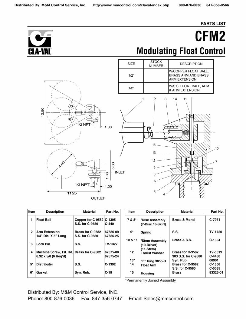
DESCRIPTION
W/COPPER FLOAT BALL,BRASS ARM AND BRASSARM EXTENSION
W/S.S. FLOAT BALL, ARM& ARM EXTENSION
STOCKNUMBER
SIZE
1/2"
1/2"
CFM2Modulating Float Control
†Permanently Joined Assembly
CLA-VAL copyright Cla-Val 2003 Printed in USA Specifications subject to change without notice.P.O. Box 1325 • Newport Beach, CA 92659-0325 • Phone: 949-722-4800 • Fax: 949-548-5441 • E-mail: [email protected] • Website cla-val.com©
PL-CFM2 (R-9/03)
PARTS LIST
Item
1
2
3
4
5*
6*
Description
Float Ball
Arm Extension1/4” Dia. X 5” Long
Lock Pin
Machine Screw, Fil. Hd.6.32 x 5/8 (6 Req’d)
Distributer
Gasket
Material
Copper for C-9582S.S. for C-9580
Brass for C-9582S.S. for C-9580
S.S.
Brass for C-9582
S.S.
Syn. Rub.
Part No.
C-1395C-440
67586-0967586-25
TV-1327
67575-0867575-24
C-1392
C-19
Item
7 & 8*
9*
10 & 11
12
13*14
15
Description
†Disc Assembly(7-Disc / 8-Skirt)
Spring
†Stem Assembly(10-Driver)(11-Stem)Thrust Washer
“0” Ring 3855-BFloat Arm
Housing
Material
Brass & Monel
S.S.
Brass & S.S.
Brass for C-9582303 S.S. for C-9580Syn. Rub.Brass for C-9582S.S. for C-9580Brass
Part No.
C-7071
TV-1420
C-1304
TV-5619C-443000901C-1306C-508583323-01
Distributed By: M&M Control Service, INC.
Phone: 800-876-0036 Fax: 847-356-0747 Email: [email protected]
Distributed By: M&M Control Service, Inc. http://www.mmcontrol.com/claval-index.php 800-876-0036 847-356-0566

The strainer is designed for use in conjunction with a Cla-ValMain Valve, but can be installed in any piping system wherethere is a moving fluid stream to keep it clean. When it is usedwith the Cla-Val Valve, it is threaded into the upstream body portprovided for it on the side of the valve. It projects through theside of the Main Valve into the flow stream. All liquid shunted tothe pilot control system and to the cover chamber of the MainValve passes through the X46 Flow Clean Strainer.
I
C MalePipe
SAE
H
D
E
B
G
MalePipe
BWidth Across Flats
FemalePipe
A
D
EF
• Self Scrubbing Cleaning Action• Straight Type or Angle Type
The Cla-Val Model X46 Strainer is designed to prevent passage offoreign particles larger than .015". It is especially effective againstsuch contaminant as algae, mud, scale, wood pulp, moss, and rootfibers. There is a model for every Cla-Val. valve.
The X46 Flow Clean strainer operates on a velocity principle utilizingthe circular "air foil" section to make it self cleaning. Impingement ofparticles is on the "leading edge" only. The low pressure area on thedownstream side of the screen prevents foreign particles from clog-ging the screen. There is also a scouring action, due to eddy cur-rents, which keeps most of the screen area clean.
Dimensions (In Inches)
INSTALLATION
X46 Angle Type B (In Inches)
B(NPT) C(SAE) D E H I
1/8 1/4 1-3/8 5/8 7/8 1/4
1/4 1/4 1-3/4 3/4 1 3/8
3/8 1/4 2 7/8 1 1/2
3/8 3/8 1-7/8 7/8 1 1/2
1/2 3/8 2-3/8 1 1-1/4 5/8
X46A Straight
X46B Angle
X46A Straight Type A (In Inches)A B D E F G I
1/8 1/8 1-3/4 3/4 1/2 1/2 1/4
1/4 1/4 2-1/4 1 3/4 3/4 3/8
3/8 3/8 2-1/2 1 7/8 7/8 1/2
3/8 1/2 2-1/2 1-1/4 1/2 7/8 3/4
1/2 1/2 3 1-1/4 1 1-1/8 3/4
3/8 3/4 3-3/8 2 1/2 1 7/8
3/4 3/4 4 2 1 1-1/2 7/8
3/8 1 4-1/4 2-3/4 1/2 1-3/8 7/8
1 1 4-1/2 2-3/4 1-1/4 1-3/4 7/8
1/2 1 4-1/4 2-3/4 1/2 1-3/8 7/8
Flow Clean StrainerX46
INSPECTIONInspect internal and external threads for damage or evidenceof cross-threading. Check inner and outer screens for clogging,embedded foreign particles, breaks, cracks, corrosion, fatigue,and other signs of damage.
CLEANINGAfter inspection, cleaning of the X46 can begin. Water service usually will producemineral or lime deposits on metal parts in contact with water. These deposits canbe cleaned by dipping X46 in a 5-percent muriatic acid solution just long enough fordeposit to dissolve. This will remove most of the common types of deposits.Caution: use extreme care when handling acid. If the deposit is not removed byacid, then a fine grit (400) wet or dry sandpaper can be used with water. Rinse partsin water before handling. An appropriate solvent can clean parts used in fueling ser-vice. Dry with compressed air or a clean, lint-free cloth. Protect from damage anddust until reassembled.
REPLACEMENTIf there is any sign of damage, or if there is the slightest doubt that the Model X46Flow Clean Strainer may not afford completely satisfactory operation, replace it. UseInspection steps as a guide. Neither inner screen, outer screen, nor housing is fur-nished as a replacement part. Replace Model X46 Flow Clean Strainer as a com-plete unit.
When ordering replacement Flow-Clean Strainers, it is important to determine pipesize of the tapped hole into which the strainer will be inserted (refer to column A orF), and the size of the external connection (refer to column B or G).
When Ordering,Please Specify:
• Catalog Number X46• Straight Type or Angle Type• Size Inserted Into and Size Connection• Materials
DISASSEMBLYDo not attempt to remove the screens from the strainer housing.
MODEL
INSTALLATION / OPERATION / MAINTENANCE
CLA-VAL copyright Cla-Val 2003 Printed in USA Specifications subject to change without notice.P.O. Box 1325 • Newport Beach, CA 92659-0325 • Phone: 949-722-4800 • Fax: 949-548-5441 • E-mail: [email protected] • Website cla-val.com' N-X46 (R-9/03)
(NPT) (NPT)
X46B
X46A
Distributed By: M&M Control Service, INC.
Phone: 800-876-0036 Fax: 847-356-0747 Email: [email protected]
Distributed By: M&M Control Service, Inc. http://www.mmcontrol.com/claval-index.php 800-876-0036 847-356-0566

CLA-VAL copyright Cla-Val 2003 Printed in USA Specifications subject to change without notice.P.O. Box 1325 • Newport Beach, CA 92659-0325 • Phone: 949-722-4800 • Fax: 949-548-5441 • E-mail: [email protected] • Website cla-val.com©
PL-CK2 (R-9/03)
Distributed By: M&M Control Service, INC.
Phone: 800-876-0036 Fax: 847-356-0747 Email: [email protected]
Distributed By: M&M Control Service, Inc. http://www.mmcontrol.com/claval-index.php 800-876-0036 847-356-0566

CLA-VAL copyright Cla-Val 2003 Printed in USA Specifications subject to change without notice.P.O. Box 1325 • Newport Beach, CA 92659-0325 • Phone: 949-722-4800 • Fax: 949-548-5441 • E-mail: [email protected] • Website cla-val.com©
INSTALLATION / OPERATION / MAINTENANCE
Flow ControlCVMODEL
N-CV (R-9/03)
DESCRIPTIONThe Cla-Val Model CV Flow Control is a simply-designed,spring-loaded check valve. Rate of flow is full flow in one direc-tion and restricted in other direction. Flow is adjustable in therestricted direction. It is intended for use in conjunction with apilot control system on a Cla-Val Automatic Control Valve.
OPERATIONThe CV Flow Control permits full flow from port A to B, andrestricted flow in the reverse direction. Flow from port A to Blifts the disc from seat, permitting full flow. Flow in the reversedirection seats the disc, causing fluid to pass through the clear-ance between the stem and the disc. This clearance can beincreased, thereby increasing the restricted flow, by screwingthe stem out, or counter-clockwise. Turning the stem in, orclockwise reduces the clearance between the stem and thedisc, thereby reducing the restricted flow.’
INSTALLATIONInstall the CV Flow Control as shown in the valve schematic Allconnections must be tight to prevent leakage.
DISASSEMBLYFollow the sequence of the item numbers assigned to theparts in the cross sectional illustration for recommendedorder of disassembly.
Use a scriber, or similar sharp-pointed tool to remove O-ringfrom the stem.
INSPECTIONInspect all threads for damage or evidence of cross- thread-ing. Check mating surface of seat and valve disc for exces-sive scoring or embedded foreign particles. Check spring forvisible distortion, cracks and breaks. Inspect all parts fordamage, corrosion and cleanliness.
CLEANINGAfter disassembly and inspection, cleaning of the parts canbegin. Water service usually will produce mineral or limedeposits on metal parts in contact with water. Thesedeposits can be cleaned by dipping the parts in a 5-percentmuriatic acid solution just long enough for deposits to dis-solve. This will remove most of the common types ofdeposits. Caution: use extreme care when handling acid.If the deposit is not removed by acid, then a fine grit (400)wet or dry sandpaper can be used with water. Rinse partsin water before handling. An appropriate solvent can cleanparts used in fueling service. Dry with compressed air or aclean, lint-free cloth. Protect from damage and dust untilreassembled.
REPAIR AND REPLACEMENTMinor nicks and scratches may be polished out using a finegrade of emery or crocus cloth; replace parts if scratchescannot be removed.
Replace O-ring packing and gasket each time CV FlowControl is overhauled.
Replace all parts which are defective. Replace any partswhich create the slightest doubt that they will not afford com-pletely satisfactory operation. Use Inspection steps as aguide.
REASSEMBLYReassembly is the reverse of disassembly; no special toolsare required.
TEST PROCEDURENo testing of the flow Control is required prior to reassemblyto the pilot control system on Cla-Val Main Valve.
Distributed By: M&M Control Service, INC.
Phone: 800-876-0036 Fax: 847-356-0747 Email: [email protected]
Distributed By: M&M Control Service, Inc. http://www.mmcontrol.com/claval-index.php 800-876-0036 847-356-0566

3/8" Flow ControlCV
2.12MAX
STAMP PART NO. ONSMOOTH SURFACE
RESTRICTEDFLOW
3/8 - 18 NPT1.84
ADJUSTING STEM(TURN CLOCKWISE TOINCREASE RESTRICTION)
1
7
2
10
9
8
6
5
4
3
.85
FREE FLOW
BAR STOCKCONFIGURATION
When ordering parts,please specify:
• Number Stamped on Side • Description (CV Flow Control)• Part Description• Material
ITEM DESCRIPTION QUAN.
1 Cap (SS only) 1
2 Nut, Jam 1
3 Seat 1
4 Gasket 1
5 Disc 1
6 Spring 1
7 Ring, Retaining 1
8 Stem 1
9 O-Ring 1
10 Housing 1
CLA-VAL copyright Cla-Val 2003 Printed in USA Specifications subject to change without notice.P.O. Box 1325 • Newport Beach, CA 92659-0325 • Phone: 949-722-4800 • Fax: 949-548-5441 • E-mail: [email protected] • Website cla-val.com© PL-CV (R-9/03)
PARTS LIST
Distributed By: M&M Control Service, INC.
Phone: 800-876-0036 Fax: 847-356-0747 Email: [email protected]
Distributed By: M&M Control Service, Inc. http://www.mmcontrol.com/claval-index.php 800-876-0036 847-356-0566

SIZE STOCK NUMBER A B HEX(NTP) (inch) (Inch)
3/8 9834501A 2.06 1.06
1/2 9834502J 2.12 1.38
ITEM DESCRIPTION
1 Retainer, Seal
2 O-Ring
3 Retainer, Valve
4 Seal, Valve Ring
5 Plate Valve
Check ValveCDC-1
Available only in replacement assembly.
CLA-VAL copyright Cla-Val 2003 Printed in USA Specifications subject to change without notice.P.O. Box 1325 • Newport Beach, CA 92659-0325 • Phone: 949-722-4800 • Fax: 949-548-5441 • E-mail: [email protected] • Website cla-val.com©
PL-CDC-1 (R-4/04)
PARTS LIST
Material: Bronze
Distributed By: M&M Control Service, INC.
Phone: 800-876-0036 Fax: 847-356-0747 Email: [email protected]
Distributed By: M&M Control Service, Inc. http://www.mmcontrol.com/claval-index.php 800-876-0036 847-356-0566

ITEM DESCRIPTION MATERIAL
1 Pipe Plug Steel
2 Strainer Plug Brass
3 Gasket Copper
4* Screen Monel
5 Body Brass
12345
3/8 NPT
2.06
2.72
SIZE STOCK NUMBER
3/8 x 3/8 33450J
StrainerX43
*Replacement screen stock number 68373A.All other parts available only in replacement assembly.
Standard 60 mesh pilot system strainer for fluid service.
CLA-VAL copyright Cla-Val 2003 Printed in USA Specifications subject to change without notice.P.O. Box 1325 • Newport Beach, CA 92659-0325 • Phone: 949-722-4800 • Fax: 949-548-5441 • E-mail: [email protected] • Website cla-val.com©
PL- X43 (R-9/03)
PARTS LIST
Distributed By: M&M Control Service, INC.
Phone: 800-876-0036 Fax: 847-356-0747 Email: [email protected]
Distributed By: M&M Control Service, Inc. http://www.mmcontrol.com/claval-index.php 800-876-0036 847-356-0566

Cla-Val ProductIdentification
Proper Identification
For ordering repair kits, replacement parts, or forinquiries concerning valve operation it is important toproperly identify Cla-Val products already in service.Include all nameplate data with your inquiry. Pertinentproduct data includes valve function, size, material,pressure rating, end details, type of pilot controlsused and control adjustment ranges.
Identification Plates
For product identification, cast in body markings aresupplemented by identification plates as illustrated onthis page. The plates, depending on type and size ofproduct, are mounted in the most practical position. Itis extremely important that these identificationplates are not painted over, removed, or in anyother way rendered illegible.
INLETEINTRITTENTREEENTRADA
SIZE &CAT NO.
STOCKNO. CODE
MFD. BY CLA-VALNEWPORT BEACH, CALIF, U.S.A.
RESERVOIREND
INLET
INLET
SIZE &CAT NO.
STOCKNO.
FLOWMFD. BY CLA-VAL NEWPORT BEACH, CALIF. U.S.A.
CODE
C
¤
“
SIZE &CAT NO.
STOCKNO.
SPRINGRANGE
MFD. BY CLA-VAL NEWPORT BEACH, CALIF. U.S.A.
SIZE &CAT NO.
STOCKNO.
CODE
MFD. BY CLA-VALNEWPORT BEACH, CALIF.
U.S.A.
C
¤
“
DO NOT REMOVE
THIS VALVE HAS BEEN MODIFIEDSINCE ORIGINAL SHIPMENT FROMFACTORY. WHEN ORDERING PARTSAND/ OR SERVICE SUPPLY DATA FROMTHIS PLATE & ALL OTHER PLATES ON ORIGINAL VALVE.
REDUCED PRESSURE BACKFLOW PREVENTION DEVICE
STK.NO.
SER.NO.
CAT.
NO.RP-4
CLA-VAL NEWPORT BEACH, CA.
This brass plate appears on valves sized 21/2" and largerand is located on the top of the inlet flange.
These two brass plates appear on 3/8", 1/2", and 3/4" sizevalves and are located on the valve cover.
These two brass plates appear on 1" through 3" size
screwed valves or 1" through 2" flanged valves . It islocated on only one side of the valve body.
This brass plate appears on altitude valves only and isfound on top of the outlet flange.
This brass plate is used to identify pilot control valves.The adjustment range is stamped into the plate.
This tag is affixed to the cover of the pilot control valve.The adjustment range appears in the spring range
section.
This aluminum plate is included in pilot systemmodification kits and is to be wired to the new pilot
control system after installation.
This brass plate is on our backflow preventionassemblies. It is located on the side of the number two
check (2" through 10"). The serial number of theassembly is also stamped on the top of the inlet flange of
the number one check.
How to OrderTM
TM
Distributed By: M&M Control Service, Inc. http://www.mmcontrol.com/claval-index.php 800-876-0036 847-356-0566

HOW TO ORDER
There are many valves and controls manufactured by Cla-Valthat are not listed due to the sheer volume. For information notlisted, please contact your local Cla-Val office or our factoryoffice located at:
SPECIFY WHEN ORDERING• Model Number • Valve Size• Globe or Angle Pattern • Screwed or Flanged• Adjustment Range • Body and Trim Materials(As Applicable) • Optional Features
• Pressure Class
UNLESS OTHERWISE SPECIFIED• Globe or angle pattern are the same price• Ductile iron body and bronze trim are standard• X46 Flow Clean Strainer or X43 “Y” Strainer are included• CK2 Isolation Valves are included in price on 4” and larger valve sizes (6” and larger on 600 Series)
P. O. Box 1325Newport Beach, California 92659-0325
(949) 722-4800FAX (949) 548-5441
LIMITED WARRANTYAutomatic valves and controls as manufactured by Cla-Val are warrantedfor three years from date of shipment against manufacturing defects inmaterial and workmanship which develop in the service for which they aredesigned, provided the products are installed and used in accordancewith all applicable instructions and limitations issued by Cla-Val.
We will repair or replace defective material, free of charge, which isreturned to our factory, transportation charges prepaid, provided that, afterinspection, the material is found to have been defective at time ofshipment. This warranty is expressly conditioned on the purchaser’s givingCla-Val immediate written notice upon discovery of the defect.
Components used by Cla-Val but manufactured by others, are warrantedonly to the extent of that manufacturer’s guarantee.
This warranty shall not apply if the product has been altered or repaired byothers, and Cla-Val shall make no allowance or credit for such repairs oralterations unless authorized in writing by Cla-Val.
DISCLAIMER OF WARRANTIES AND LIMITATIONS OF LIABILITYThe foregoing warranty is exclusive and in lieu of all otherwarranties and representations, whether expressed, implied, oral orwritten, including but not limited to any implied warranties ormerchantability or fitness for a particular purpose. All such otherwarranties and representations are hereby cancelled.
Cla-Val shall not be liable for any incidental or consequential loss,damage or expense arising directly or indirectly from the use of theproduct. Cla-Val shall not be liable for any damages or charges forlabor or expense in making repairs or adjustments to the product.Cla-Val shall not be liable for any damages or charges sustained inthe adaptation or use of its engineering data and services. Norepresentative of Cla-Val may change any of the foregoing orassume any additional liability or responsibility in connection withthe product. The l iabil i ty of Cla-Val is l imited to materialreplacements F.O.B. Newport Beach, California.
TERMS OF SALE
ACCEPTANCE OF ORDERS
All orders are subject to acceptance by our main office at Newport Beach, California.
CREDIT TERMS
Credit terms are net thirty (30) days from date of invoice.
PURCHASE ORDER FORMS
Orders submitted on customer’s own purchase order forms will be accepted onlywith the express understanding that no statements, clauses, or conditions containedin said order form will be binding on the Seller if they in any way modify the Seller’sown terms and conditions of sales.
PRODUCT CHANGES
The right is reserved to make changes in pattern, design or materials when deemednecessary, without prior notice.
PRICES
All prices are F.O.B. Newport Beach, California unless expressly stated otherwise onour acknowledgement of the order. Prices are subject to change without notice. Theprices at which any order is accepted are subject to adjustment to the Seller’s pricein effect at the time of shipment. Prices do not include sales, excise, municipal, stateor any other Government taxes. Minimum order charge $75.00.
RESPONSIBILITY
We will not be responsible for delays resulting from strikes, accidents, negligence ofcarriers, or other causes beyond our control. Also, we will not be liable for anyunauthorized product alterations or charges accruing there from.
RISK
All goods are shipped at the risk of the purchaser after they have been delivered byus to the carrier. Claims for error, shortages, etc., must be made upon receipt ofgoods.
EXPORT SHIPMENTS
Export shipments are subject to an additional charge for export packing.
RETURNED GOODS
1. Customers must obtain written approval from Cla-Val prior to returning anymaterial.
2. Cla-Val reserves the right to refuse the return of any products.
3. Products more than six (6) months old cannot be returned for credit.
4. Specially produced, non-standard models cannot be returned for credit.
5. Rubber goods such as diaphragms, discs, o-rings, etc., cannot be returned forcredit, unless as part of an unopened vacuum sealed repair kit which is lessthan six months old.
6. Goods authorized for return are subject to a 35% ($75 minimum) restockingcharge and a service charge for inspection, reconditioning, replacement ofrubber parts, retesting, repainting and repackaging as required.
7. Authorized returned goods must be packaged and shipped prepaid to Cla-Val,1701 Placentia Avenue, Costa Mesa, California 92627.
CLA-VALPO Box 1325 Newport Beach CA 92659-0325
Phone: 949-722-4800 • Fax: 949-548-5441CLA-VAL CANADA CLA-VAL EUROPE4687 Christie DriveBeamsville, OntarioCanada LOR 1B4Phone: 905-563-4963Fax: 905-563-4040
Chemin des Mésanges 1CH-1032 Romanel/Lausanne, SwitzerlandPhone: 41-21-643-15-55Fax: 41-21-643-15-50
'COPYRIGHT CLA-VAL 2003 Printed in USASpecifications subject to change without notice. www.cla-val.com
E-Product I.D. (R-9/03)
TM
Represented By:Distributed By:
M&M Control Service, INC.
Phone: 800-876-0036
Fax: 847-356-0747
Email: [email protected]
Distributed By: M&M Control Service, Inc. http://www.mmcontrol.com/claval-index.php 800-876-0036 847-356-0566

Complete Replacement Diaphragm Assemblies for 100-01 and 100-20 Hytrol Main ValvesFor: Hytrol Main Valves with Ductile Iron, Bronze Trim Materials—125/150 Pressure Class Only.FACTORY ASSEMBLEDIncludes: Stem, Disc Guide, Disc, Disc Retainer, Spacer Washers, Diaphragm, Diaphragm Washerand Stem Nut.
3/8"1/2" - 3/4"
1"1 1/4"-1 1/2"
2"2 1/2"
3"4"
(Also 81-01 )(Also 81-01 )
N/AN/AN/AN/AN/AN/A
C2524BC2525J
6"8"10"12"14"16"20"24"
40456G45276D81752J85533J89067D89068B
N/AN/A
33273E40456G45276D81752J
N/A85533J89068B89068B
Valve Size
Valve Size
49097KC2518DC2520KC2522 FC2524BC2523DC2525J33273E
100-01 100-20
Diaphragm AssemblyStock Number
100-01 100-20
Diaphragm AssemblyStock Number
3/8"1/2" - 3/4"
1"1 1/4" - 1 1/2"
2"2 1/2"
3"4"6"8"
10"12"14"16"20"24"
(Also 81-01 )(Also 81-01 )
N/AN/AN/AN/AN/AN/A
9169805A9169812G9169813E9169815K9817901D9817902B
N/A9817903K9817905E9817905E
3/8"1/2" - 3/4"
1"1 1/4” - 1 1/2"
2"2 1/2"
3"4"6"8"
9169806J9169807G9169808E9169809C9169810A9169817F9169818D9169819B9169820K
N/A
N/AN/AN/AN/AN/AN/A
9169810A9169818D9169819B9169820K
Valve Size
Valve Size
9169801K9169802H9169803F9169804D9169805A9169811J9169812G9169813E9169815K9817901D9817902B9817903K9817904H9817905E
N/AN/A
100-01 100-20
Repair KitStock Number
100-01 100-20
Repair KitStock Number
Repair Kits for 100-01/100-20 Hytrol ValvesFor: Hytrol Main Valves—125/150 Pressure Class Only.Supplied Shrink Wrapped (4" and smaller) or Bagged (6" and larger)Includes: Diaphragm, Disc (or Disc Assembly) and spare Spacer Washers.
(Also 81-01 )(Also 81-01 )
REPAIR KITS
When ordering, please give complete nameplate data of the valve and/or control being repaired.MINIMUM ORDER CHARGE APPLIES.
Buna-N® Standard Material Viton (For KB Valves)
MODEL
INSTALLATION / OPERATION / MAINTENANCE
Distributed By: M&M Control Service, Inc. http://www.mmcontrol.com/claval-index.php 800-876-0036 847-356-0566

Repair Kits for 100-02/100-21 Powertrol and 100-03/100-22 Powercheck Main ValvesFor: Powertrol and Powercheck Main Valves—125/150 Pressure Class OnlySupplied Shrink Wrapped (4" and Smaller) or Bagged (6" and larger)Includes: Diaphragm, Disc (or Disc Assembly) and spare Spacer Washers.
Repair Kits for Pilot Control ValvesSupplied Shrink Wrapped Includes: Diaphragm, Disc (or Disc Assembly), O-Rings, Gaskets or spare Screws as appropriate.
3/8"1/2" - 3/4"
1"1 1/4" & 1 1/2"
2"
9169901H9169902F9169903D9169904B9169905J
2 1/2"3"4"6"8"10"
9169910J9169911G9169912E9169913C99116G
N/A
N/A9169905J9169911G9169912E9169913C99116G
CDBCDB-7CDH-2CDHS-2CDHS-2BCDHS-2FCDHS-3C-A2CDHS-8ACDHS-18CDS-4CDS-5CDS-6CFM-2, CFM-9, CFCM-M1
9170006C9170017K18225D44607A9170004H9170005E24657K2666901A9170003K9170014G14200A20119301A12223E
CFM-7 & 7-ACRA (w/bucking spring)
CRD (w/bucking spring)
CRD (no bucking spring)
CRD-22CRL (55F, 55L)CRL-4ACRL-5 (55B)CRL-5A (55G)CVX105L (O-ring)102B-1102C-2 & -3
1263901K9170001D9170002B9170003K98923G9170007A43413E65755B20666E9170019F00951E1502201F1726201F
CDB-KBCRA-KBCRD-KB (w/bucking spring)
CRL-KBCDHS-2BKBCDHS-2FKBCDHS-18KB (no bucking spring)
102C-KBBuna-N®
9170012A9170018H9170008J9170013J9170010E9170011C9170009G1726202D
PilotControl
KitStock
NumberPilot
Control
KitStock
NumberPilot
Control
KitStock
Number
BUNA-N® (Standard Material) VITON (For KB Controls)
CF1-C1CF1-ClCFC2-C1CSM 11-A2-2CSM 11-A2-233A 1"33A 2"
Pilot Assembly OnlyComplete Float Control less Ball & RodDisc, Distributor & SealsMechanical Parts Assy.Pilot Assembly OnlyComplete Internal Assembly & SealComplete Internal Assembly & Seal
89541H89016A2674701E97544B18053K2036030B2040830J
Control Description Stock Number
Repair Assemblies (In Standard Materials Only)
Valve Size
ValveSize
Kit Stock NumberKit Stock Number100-02 100-02 &100-03 100-21 &100-22
Larger Sizes: Consult Factory.
CRD DISC RET. (SOLID)
CRD DISC RET. (SPRING)
C5256HC5255K
When ordering, please give complete nameplate data of the valve and/or control being repaired. MINIMUM ORDER CHARGE APPLIES
Repair Kits for 100-04/100-23 Hy-Check Main ValvesFor: Hy-Check Main Valves—125/150 Pressure Class OnlySupplied Shrink Wrapped (4" and Smaller) or Bagged (6" and larger)Includes: Diaphragm, Disc and O-Rings and full set of spare Spacer Washers.
4”6”8”
10”
20210901B20210902A20210903K20210904J
N/A20210901B20210902A20210903K
12”14”16”
20”, 24”
20210905H20210906G20210907F
N/A
20210904JN/A
20210905H20210907F
ValveSize
Valve Size
Kit Stock Number100-04 100-23
Kit Stock Number100-04 100-23
Larger Sizes: Consult Factory.
CLA-VAL copyright Cla-Val 2003 Printed in USA Specifications subject to change without notice.P.O. Box 1325 • Newport Beach, CA 92659-0325 • Phone: 949-722-4800 • Fax: 949-548-5441 • E-mail: [email protected] • Website cla-val.com' N-RK (R-9/03)
Distributed By: M&M Control Service, INC.
Phone: 800-876-0036 Fax: 847-356-0747 Email: [email protected]
Distributed By: M&M Control Service, Inc. http://www.mmcontrol.com/claval-index.php 800-876-0036 847-356-0566


