
Abstract:Results of the first student experiment using a MEDIPIX-type detector for CR imagingin stratospheric environment are presented. The detector was used in its trackingmode allowing it to operate as an "active nuclear emulsion". The actual flight time wasover 4 hours, with 2 hours at stable floating altitude of 26km. Different types of cosmicray particles were acquired in the stratospheric radiation environment, sorted andanalyzed. Detector performance is evaluated for further design implications ofadvanced concept focusing on Cosmic Ray Induced Ionization measurement.
MEDIPIX CR tracking device
flown on ESA BEXUS-7 stratospheric balloon flight
[1] Department of Space Science, LTU, Kiruna, Sweden [2] Faculty of Electrical Engineering, Czech Technical University in Prague [3] Institute of Experimental and Applied Physics, CTU Prague, Czech Rep.
J. Urbar [1], J. Scheirich [2], J. Jakubek [3]

* Ionisation Rate* Ion Concentration* Global Electric Circuit- Commmunication - E-Fields, - Lightnings, - Thunderclouds- Air Conductivity
Cosmic Ray Extensive Airshowers (CR EAS)
At altitudes of ~3 to 35 km, cosmic rays are practically the only ionisation source
Shower composition:– p (protons), π (pions)produced in strong interactions– μ (muons) decayed from π– e-, e+, γ from electromag. int. – nuclei produced by interactions of secondaries– gamma decayed from nuclei

• Planar pixel detector (700μm Si) bump-bond to read-out chip
Ionizing particle creates a charge in a sensitive volume
The charge is amplified and compared with a threshold
Digital counter is incremented.
Solid State imaging detector Medipix2developed at CERN with USB interface developed at IEAP CTU in Prague
3

TimePiX System Overview Single Board computer
AMD Geode 500MHz Ethernet Interface Solid State HDD
(Compact Flash) Medipix2 Detector
Particle detectors are based on:Energy deposited in the active material of the detector is transformed into charge (by ionization in gaseous detectors/ by excitation of electron-hole pairs in semiconductor ones). The charge is then collected by read-out electronics.
4

Unique tracking data for particle type identificationIdentification criteria:
track shape (pattern recognitionalgorithms: cluster area, lineardimensions, complexity)
total energy deposited in the sensor (from the amplitude of the back-plane pulse MEDIPIX2)
Sensitivity range 8keV ~ 100MeV
Heavy charged particles
Fast light charged particles
Slow light charged particles
Photon conversion
5

Photon passage through box wall by GEANT4
γ
Photons are absorbed or reflected by box wall.
At 20 keV, 80% photons will pass through.Threshold on collected charge is applied on everypixel for correction of specific deposited chargeeffect of e-h pair creation (3.65 eV).

Electron passage through box wall by GEANT4
e−
Electrons loose much more energy than photonssince they have a charge. From this reason about50% electrons of 2 MeV will be absorbed in the wallas the simulations demonstrate. PE box enclosing themain detector enables registration of electrons in theMeV range, while converting them to lower energies.Only then they can leave charge passing the detectorefficiently enough. Overall charge deposited byelectrons sensor >10x larger compared to photons.
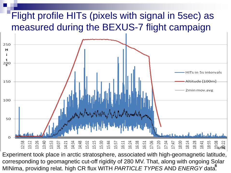
Flight profile HITs (pixels with signal in 5sec) as measured during the BEXUS-7 flight campaign
8
Experiment took place in arctic stratosphere, associated with high-geomagnetic latitude,corresponding to geomagnetic cut-off rigidity of 280 MV. That, along with ongoing SolarMINima, providing relat. high CR flux WITH PARTICLE TYPES AND ENERGY data.

Altitude dependent ionization rate in Medipix2
9

Medipix systems’ flight performance
10
Ionizing radiation tracks acquired in stratosphere, particle pattern identification-by-track concept:a- Heavy charged particles, b- Slow light charged particles,c- Fast light charged particles, d- X-rays, low energy gamma

CRindIons team
Luleå University of Technology, SwedenCzech Technical University in Prague, Charles University in Prague, Czech Republic
Novel concept of parallel in-situ measurement of the CosmicRay
Ionization-vetoed breakdown Voltage =>Formation of ions in Earth Atmosphere
Induced Ionization rate by SSD with the ion concentration by means of:
Ongoing STUDENT project on BEXUS8/9 with launch campaign Oct 2009

CRIndIons: Multiple Objectives
On-flight comparison between TWO Medipix2 detectors – one with fast NEUTRON converter (PE)
Intercalibration of multiple SSDs – Medipix2 with STANDARD RAS sonde Geiger tube (on-ground)
Ionization rate measurement ~ Medipix2 pixel HITs Breakdown voltage measured by 2 IONIZ. TUBEs Particle energy estimation from backside pulse Coinc. Medipix HW triggershower arrival direction 2 IONIZ. Tubes w.diff.shield CR-induced/ambient Aerosol conditions (estimate by ESRANGE LIDAR)
12

Ionizing particle FLUXes – BUT w/o particle types...
Monthly averaged fluxes of ionizing particles in the atmosphere over Murmansk region as measured by omnidir. Geiger counter (Bazilevskaya, 2007)
13

Cosmic ray-induced Ion Production rate andIon Concentration in the Earth‘s Atmosphere
At altitudes of ~3 to 35 km, cosmic rays are practically the only ionisation source
Ion production rate qq = I ρ σ / M
I = I (h, Rc, Φ) cosmic ray flux
ρ air density
σ eff. ionisation cross section
≈ 2 x 10-18 cm2 at h ≤ 20 km
M average mass of air atom
Ion concentration n
q = α n2
α 3D recombination coefficient
q(h) = β(h) n(h)
β(h) linear recombination coeff 14Stozhkov, 2003

Left: altitudinal profiles of CR fluxes J(h), Right: ion production rate q(h) The values of J(h) and q(h) were measured and calculated at the latitudes with different values of Rc (shown near each curve) and correspond to the period of high solar activity level (Stozkhov, 2008)
0
5
10
15
20
25
30
35
0 1 2 3
J (h ), cm-2 s-1
h, k
m
0 GV3.2 GV5.2 GV
17 GV
a
0
5
10
15
20
25
30
35
0 10 20 30q (h ), cm-3 s-1
0 GV
3.2 GV5.2 GV17 GV
b
15
Modeled CR fluxes vs. Ion production rates (Stozhkov, 2008)

Left: Altitudinal profiles of light ion concentrations n(h) Right: Altitudinal profiles of CR fluxes J(h) These data were obtained during solar activity maximum at the latitudes with different values of Rc (labels near curves) (by Stozkhov, 2008)
0
10
20
30
0 1 2 3n (h ), 103 cm-3
h, k
m
17.3 5.3 30.6
a
0
10
20
30
0 1 2J (h ), cm-2 s-1
17.3 5.6 3.4 0.03
b
16
MEASURED Ion concentrat. vs. CR FLUXes (Stozhkov, 2008)

OuluCRAC model for Cosmic Ray Induced Ionization:Altitude on geomag. latitude dependence (Usoskin,2004)
17

Modeled combined ionization effect of GCR (Usoskin, 2007)

Ionization by GCR & SCR as simulated by PLANETOCOSMICSBern Model, using GEANT4 CERN MC package: http://cosray.unibe.ch/~laurent/planetocosmics
(Desorgher et al., AOGS 2004)
19

CRIndIons System Overview
2 Medipix2 detectors Ionization Tube module
Single Board Industrial Computer AMD 500MHz
Single-chip MicroController (Ionization time measurements)
Ethernet, RS 232 Solid State HDD (CF)
backup flash memory
20

AcknowledgmentsDetector providers
Launch opportunity


