
TI Solution for Vacuum Cleaning Robot
2
System Block Diagram Overview
TI Battery Management for Vacuum Cleaning Robot
TI Motor Driver Solution for Vacuum Cleaning Robot
TI Power Solution for Vacuum Cleaning Robot
TI TOF Technology for Vacuum Cleaning Robot
TOPICS
TI Solution for Vacuum Cleaning Robot

3
Presenter Introduction
Patrick Zeng is Field Application Engineer in South China Team and now focuses on industry market and is responsible for supporting appliances customers

System Block Diagram Overview

Typical System Block Diagram of Vacuum Cleaning Robot
BDC Motor
Driver
Digital
Processor
M AFE(Protection &
Monitor& Gauge)
MOSFET
Temp
Sensor
Suction Motor
Hall
Sensors Power Stage
Charger
Knob/Dial
User Interface
Touch
Signal Protection
ESD
LDO
Power Supply
DCDC
Signal Sampling
OP AMP
Wide Input DC
M
M
Rotating Motor
Wheel Drive Right & Left
M Side Brush
BLDC Motor
Driver MOSFET
LED
Driver
Audio
Monitor
Reset
Obstacle
Detection
Vision Sensor
Imager
Controller MCU/MPU
Power
Wide Input DC
Battery Management System

BDC Motor
Driver
Digital
Processor
DSP
M AFE(Protection &
Monitor& Gauge) BQXXX
Battery Management System
MOSFET
Temp
Sensor
Suction Motor
Hall
Sensors Power Stage
Charger BQXXX
User Interface
Signal Protection
ESD
LDO
Power Supply
DCDC
Wide Input DC
Signal Sampling
OP AMP
M
M
Rotating Motor
Wheel Drive Right & Left
M Side Brush
BLDC Motor
Driver MOSFET
LED
Driver
Audio
Monitor
Reset
3D TOF
Sensor
Vision Sensor
3D TOF
Controller MCU/MPU
Power
LDCXXX
FDCXXX
Captivate
Haptics
Typical System Block Diagram of Vacuum Cleaning Robot Wide Input DC

TI Battery Management Solution for Vacuum Cleaning Robot
7

Linear Charger
• 2s-4s SMBUS controllers
• 1s-7s w/ integrated FET
• Stand alone linear chargers (<1A)
Gauge
• Flash based (1% accuracy)
• ROM based (5% accuracy)
• Low cost gauge
• BMU (Charger and Gauge)
• Wireless Power
• Supercapacitor
• Renewable Energy Harvesting
• High cell count precision AFE & cell balancing
• Primary, secondary & total protection
• Enhanced safety w/ ID and authentication
Monitor & Protection Switch-mode Charger
• High efficiency switch-mode solutions (>1A)
• Faster and cooler (MaxChargeTM)
Energy storage and transfer
TI BMS solution makes your battery higher efficiency and safer
TI Battery Management Solution Overview

Industrial Monitoring
bq76940 Monitor Family for 18V - 48V 3 Versions: 5S, 10S, 15S
Int. ADCs for cell voltage, thermistor temp, pack current
Integrated OV, UV, OCD, SCD
Cell balancing drivers
Low–side NCH drive
2.5 / 3.3V LDO
I2C with CRC
Ship mode ICC 0.6µA
Optionally pairs with bq78350-R1 CEDV Fuel Gauge
20p TSSOP 4.4x6.5x1.2
30p TSSOP 4.4x7.8x1.2
44p TSSOP 4.4x11.3x1.2
3–6S Monitor Analog output: cell V, pack I
5mV cell voltage accuracy
Cell balancing drivers
SCD fault detect
3.3V LDO
I2C
20p TSSOP 4.4x6.5x1.2
24p VQFN 4x4x0.9
Time
Fe
atu
res &
In
teg
ratio
n
bq76940
bq76930
bq76920
bq76925
100V High–Side
Dual NCH FET Driver Companion device
See Peripheral Devices
bq76200
New
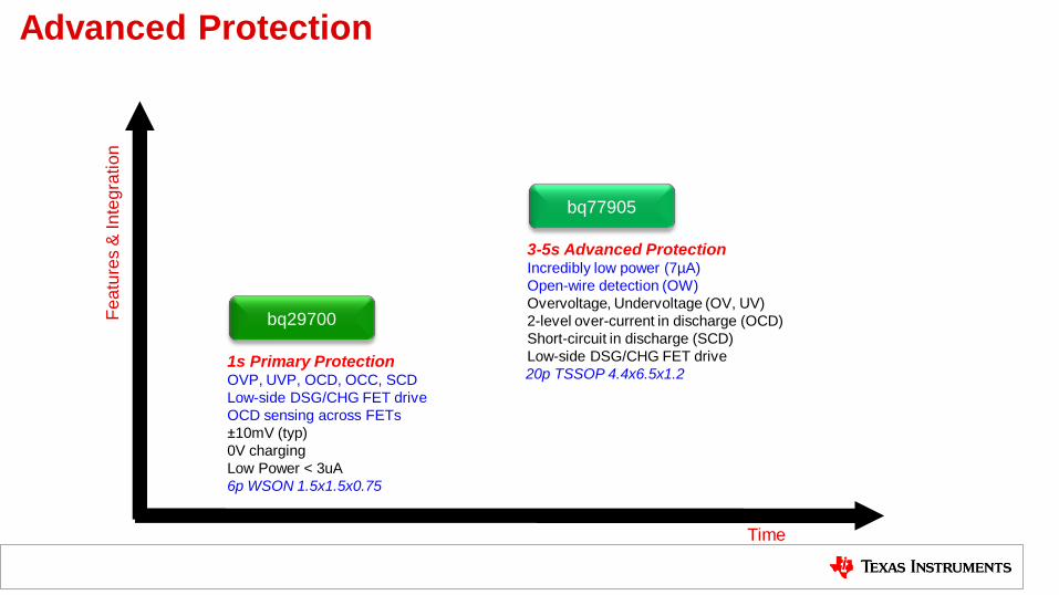
Advanced Protection
1s Primary Protection OVP, UVP, OCD, OCC, SCD
Low-side DSG/CHG FET drive
OCD sensing across FETs
±10mV (typ)
0V charging
Low Power < 3uA
6p WSON 1.5x1.5x0.75
bq29700
Time
Fe
atu
res &
In
teg
ratio
n
3-5s Advanced Protection Incredibly low power (7µA)
Open-wire detection (OW)
Overvoltage, Undervoltage (OV, UV)
2-level over-current in discharge (OCD)
Short-circuit in discharge (SCD)
Low-side DSG/CHG FET drive
20p TSSOP 4.4x6.5x1.2
bq77905
Fe
atu
res
& P
erf
orm
an
ce
1.5A iFET, 4.5-17V, 1-3 Cells
1.1MHz, Standalone
3.5x4.5mm QFN-20
bq2410x/12x
4A iFET, 4.5-17V, 1-3 Cell
Standalone
3.5x5.5mm QFN-24
bq24170/1/2
NiMH/NiCd charger
Lead Acid Charger
DIP-8 or SOIC-8
bq2000/02/13
5-28V , 33V Max, 1-7Cell LiFePO4
300kHz; >10A
DPM, Power Path
4x4mm QFN-24
bq24630
5-28V , 33V Max, 1-6Cells
600kHz; >10A
DPM, Power Path
(bq24616: JEITA)
(bq24617: 5-22V, 1-5Cells)
(bq24618: VINMIN 4.75V)
4x4mm QFN-24
bq24610/6/7/8
4.5-24V, 30V Max, 1-4 Cells
DPM, 750kHz
N-FETs Selector
3.5x3.5mm QFN-20
bq24725A
28V, 30V Max, 1-4 Cells
Turbo Boost
DPM, 750kHz
N-FETs Selector
3.5x3.5mm QFN-20
bq24735
6-24V, 2-3 Cells
NVDC-1, 600k/800k/1Mhz
N-FET Power Path
3.5x3.5mm QFN-20
bq24715
4.5-24V, 30V Max, 1-4 Cells
NVDC-1
PMON and PROCHOT
N-FET Power Path
4.0x4.0mm QFN-28
bq24770/3
1-3S w/ FETS
bq24640 Super Capacitor
600kHz; 0.5A-10A
3.5x3.5mm QFN-16
bq24650 Solar Charger MPPT
600kHz; 0.2A-10A
3.5x3.5mm QFN-16
4.5-24V, 30V Max, 1-4 Cells
Turbo Boost
PMON and PROCHOT
N-FETs Selector
4.0x4.0mm QFN-28
bq24780S
bq24133 2.5A iFET, 4.5-17V, 1-3 Cell
Standalone
3.5x5.5mm QFN-24
2.5A Version
bq24600
5-28V, 33V Max, 1-6Cells
1.2MHz; >10A
DPM, No Power Path
3.5x3.5mm QFN-16
Standalone
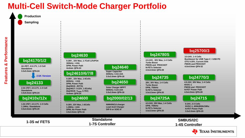
1-7S Controller SMBUS/I2C
1-4S Controller
bq25700/3
Multi-Cell Switch-Mode Charger Portfolio
3.5-24V, 1-4 Cells
Buckboost for USB Type-C / USB PD
OTG 5-20V, Current limit
PMON and PROCHOT
4.0x4.0mm QFN-32
Production
Sampling

System: •Min Voltage
•Current Inputs: •Min/Max Voltage
•Current Battery •Chemistry
•Configuration (?S?P)
•Capacity
Control Interface
Temperature Profile •Standard Cold/Hot
•JEITA
Charging •Voltage
•Current
Packaging: CSP or QFN
Key Charger Parameters to Consider
Safety and Protection •OVP (Input, BAT and OTG)
•OCP/UCP…
•Thermal Regulation
• Standalone
• I2C
• SMBus
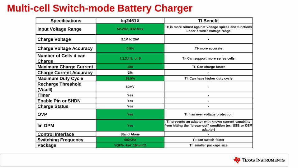
Multi-cell Switch-mode Battery Charger Specifications bq2461X TI Benefit
Input Voltage Range 5V-28V, 33V Max TI: is more robust against voltage spikes and functions
under a wider voltage range
Charge Voltage 2.1V to 26V -
Charge Voltage Accuracy 0.5% TI- more accurate
Number of Cells it can
Charge 1,2,3,4,5, or 6 TI- Can support more series cells
Maximum Charge Current 10A TI- Can charge faster
Charge Current Accuracy 3% -
Maximum Duty Cycle 99.5% TI: Can have higher duty cycle
Recharge Threshold
(V/cell) 50mV -
Timer Yes -
Enable Pin or SHDN Yes -
Charge Status Yes -
OVP Yes TI: has over voltage protection
Iin DPM Yes
TI: prevents an adaptor with known current capability
from hitting the “brown-out” condition (ex: USB or OEM
adaptor)
Control Interface Stand Alone -
Switching Frequency 600KHz TI: can switch faster
Package VQFN- 4x4: 16mm^2 TI: smaller package size

TI Motor Driver Solution for Vacuum Cleaning Robot
14

Broad portfolio of Industrial & PE Motor Drivers
Brushed-DC
Supply voltage support:
Low voltage, 12, 24, 36, 48 V
Technologies:
Integrated Current Sensing,
Smart Gate Drive
Differentiation:
Small footprint & high efficiency
Inrush current protection
Faster time to market
Hero devices:
DRV8837
DRV8870/1
DRV8701
Stepper
Supply voltage support:
Low voltage, 12, 24, 36, 48 V
Technologies:
Integrated Current Sensing,
AutoTune, & Smart Gate Drive
Differentiation:
Indexers & precision microsteps
Advanced Current Control
Passive component integration
Hero devices:
DRV8833
DRV8885
DRV8880
Brushless-DC
Supply voltage support:
Low voltage, 12, 24, 36, 48 V
Technologies:
Smart Gate Drive
1x PWM
Differentiation:
Sensorless & sensored support
Integrated shunt amplifiers
Integrated power management
Hero devices:
DRV8301
DRV8305
DRV8313
Solenoid
Supply voltage support:
Low voltage, 12, 24, 36, 48 V
Technologies:
Daisy-chain Interface
Open load detection
Differentiation:
Multi-channel drivers
Serial or parallel interface
Protection & Diagnostics
Hero devices:
DRV8839
DRV8860
DRV8844

End Equipment
Motors on ti.com

Stepper
Broad portfolio of Brushless-DC Drivers Production
Development
Status
New
Brushed-DC Solenoid Brushless-DC
Mo
tor
Po
we
r
Integrated FETs Gate Driver (External FETs)
DRV8312/32 12 to 52V @ 6.5 or 13A
DRV8313 8 to 60V @ 2.5A
DRV8308 8.5 to 32V sensored sine
DRV8307 8.5 to 32V sensored trap
DRV8301/2 6 to 60V, 2x CSA, buck
DRV8305 4.4 to 45V, Smart Gate Drive, 3x CSA, LDO
DRV8303 6 to 60V, 2x CSA
DRV8320R/3R 6 to 60V, Smart Gate Drive, 3x CSA, buck
DRV8350R/3R 8 to 100V, Smart Gate Drive, 3x CSA, buck
DRV8839 1.8 to 11V @ dual 1.8A

Stepper Brushless-DC Solenoid
Broad portfolio of Brushed-DC Drivers Production
Development
Status
New
Mo
tor
Po
we
r
Single Channel (1x BDC) Multi Channel
DRV8701 6 to 47V, Smart Gate Drive
DRV8870/71/72 6.5 to 48V @ 2.6A, integrated current sense
DRV8800/01/16 8 to 38V @ 2.8A, current shunt amplifier
DRV8828/40/42 8.2 to 45V @ 3.0 or 5.0A, regulation
DRV8830/32 2.75 to 6.8V @ 1A, voltage regulation
DRV8850 2 to 5V @ 8A, 100 mA LDO
DRV8837/37C/38/39 1.8 to 11V @ 1 A or 1.8A
DRV8412/32 12 to 52V @ dual 6 or 12A
DRV8823 8 to 32V @ quad 1.5A
DRV8802/12/13/14/41/43 8.2 to 45V @ dual 1.6 or 2.5 A, regulation
DRV8704 8 to 52V, Smart Gate Drive, dual channel
DRV8881 6.5 to 45V @ dual 2.5A, regulation, AutoTune
DRV8835/36 1.8 to 11V or 7 V @ dual 1.5A
DRV8833/33C 2.7 to 10.8V @ dual 2 or 1 A, regulation
DRV8844 8 to 60V @ dual 2.5A
DRV8848 4 to 18V @ dual 2A, regulation
Brushed-DC
DRV8873 4.5 to 38V @ 9.5 A, integrated current sense

• Printers
• Bidirectional brushed DC motor
• Vacuum Cleaner
• Single H-Bridge motor driver
• Supply voltage: 6.5 to 45 V
• Output current: 2.0A continuous / 3.5A peak • RDS(ON): 565mΩ HS + LS (at 24 V, 25°C)
• Small 8 pin HSOIC package
• Simple PWM interface with brake mode support
• Slow and mixed decay modes with fixed off-time current
regulation
• Integrated protection features including UVLO, thermal, shoot-
through and over-current (with automatic retry) protection
• Internal current sensing (DRV8871 only) and fault detect
(DRV8872 only) support
• Wide supply range supports 12V and 24V industry standard
supplies and high peak supports large startup and stall current
• Reduced component count and reduced system cost
• Scalable family of low pin count and small package size drivers
• Easy to drive and stop with a single-pin control interface
• Higher system reliability and reduced design complexity with
integrated current regulation (DRV8870 and DRV8871) and fault
detect (DRV8872) features
Applications
Benefits Features
DRV8870/1/2 3.6A Brushed DC Driver with Integrated FETs for 12V and 24V Motors
4.9 x 6.0mm, 8-pin
HSOIC package
40W
Controller
6.5V to 45V
Fault (opt)
PWM
M
Current sense (opt)
DRV887x
Motor Driver 3.5A

18-V/400-W, 98% Efficient, Compact Brushless DC Motor Drive With Stall Current Limit Reference Design
• Operates at Voltage Ranging from 5-V to 21-V (5s Li-ion Battery)
• 18-ARMS Continuous (60A Peak for 1s) Winding Current Without
Heat Sink or Airflow
• Small PCB Form Factor of 45mm x 50mm
• Inverter Drive Efficiency >98%
• Cycle –by-Cycle Overcurrent Protection with <1us Response Time
and Short Circuit Latch Protection by VDS Sensing
• Shoot-through, Under Voltage, Over Temperature & Blocked Rotor
Protection
• Operating ambient: -20 to +550C
• Small form factor enables flexible mounting and minimize impedance
on connections with high current
• Low RDS_ON MOSFETs brings high efficiency and eliminates heat sink
• Optimum inverter efficiency and EMI performance using slew rate
control of gate driver
• Three Phase Gate Driver with Internal Charge Pump Ensures
Maximum Inverter Efficiency Even at 5V DC
• Low Component count and low BOM cost
Solution Features Solution Benefits
Tools & Resources • TIDA-00772 Tools Folder
• User Guide
• Design Files: Schematics, BOM,
Gerbers, Software, and more
• Device Datasheets: • CSD18502Q5B
• DRV8305
• MSP430G2553
TI Designs Number: TIDA-00772
• SN74LVC126A
• TPD1E10B06
• LMT87

More TI Reference Design on TI.com
Products Why We Win
DRV8848 Best supply capability, high current capability, flexibility for BDC or Stepper TIDA-00297
DRV8860 Integrated serial interface, 8 channel driver saves MCU GPIOs TIDA-00117
DRV8860 Integrated serial interface, 8 channel driver saves MCU GPIOs TIDA-00117
DRV8801/16 High current capability, low solution cost w/ device integration, 2 channels TIDA-00116
DRV8307/2x Smart Gate Drive integrates passive components TIDA-00196
DRV8701
DRV8307/2x Smart Gate Drive integrates passive components
TIDA-00620
TIDA-00196
DRV8880 AutoTune automatically tunes the motor TIDA-00830
DRV8307 Smart Gate Drive integrates passive components TIDA-00196
More on TI.com

TI TOF Technology for Vacuum Cleaning Robot
22

Theory of operation
21
43arctanQQ
22
f
cd
Distance measured by emitting a modulated light and measuring phase
delay of returned light

Typical Applications

3D Technologies - Overview Time Of Flight
• Modulated light is sent out and the phase
difference between Transmit & Received
signal is measured
• Phase delay is used to calculate the depth
Stereoscopic Structured
• Two or more cameras at different angle
retrieve RGB images
• Image processing SW identifies common
feature, triangulates and finds depth
• IR source projects patterns on object. IR
sensor records the deformation of pattern
• Image is processed in software to calculate
depth
Stereoscopic vision Structured light
Time of Flight Fixed pattern Programmable Pattern (DLP)
Depth accuracy low medium (mm to cm) high (um to mm) medium mm to cm
Scanning Speed medium Slow Slow/medium fast
Distance Range Mid range Very short to mid range Very short to mid range short to long range
HW cost low middle middle/high middle
SW complexity High (correspondence prob) low/middle middle/high low
Low Light Performance weak good good good
Outdoor Performance good weak/fair weak/fair good
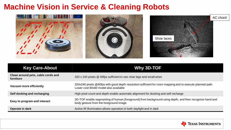
Machine Vision in Service & Cleaning Robots
Key Care-About Why 3D-TOF
Clean around pets, cable cords and
furniture 320 x 240 pixels @ 60fps sufficient to see chair legs and small wires
Vacuum more efficiently 320x240 pixels @60fps with good depth resolution sufficient for room mapping and to execute planned path.
Lower cost 80x60 model also available
Self docking and recharging High pixel count and depth enable automatic alignment for docking and self-recharge
Easy to program and interact 3D-TOF enable segmenting of human (foreground) from background using depth, and then recognize hand and
body gesture from the foreground image
Operate in dark Active IR illumination allows operation in both daylight and in dark
Shoe laces
AC chord

OPT8320 CDK
OPT8241 CDK
Voxel
SDK
Solutions Development
Kits SDK
Viewer, Demos & Reference
Designs
3D ToF Solutions
VoxelViewer
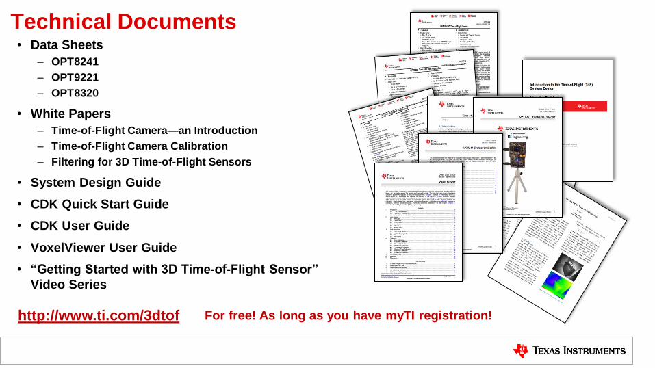
Technical Documents • Data Sheets
– OPT8241
– OPT9221
– OPT8320
• White Papers
– Time-of-Flight Camera—an Introduction
– Time-of-Flight Camera Calibration
– Filtering for 3D Time-of-Flight Sensors
• System Design Guide
• CDK Quick Start Guide
• CDK User Guide
• VoxelViewer User Guide
• “Getting Started with 3D Time-of-Flight Sensor”
Video Series
http://www.ti.com/3dtof For free! As long as you have myTI registration!

Thanks
29

30
IMPORTANT NOTICE FOR TI DESIGN INFORMATION AND RESOURCES
Texas Instruments Incorporated (‘TI”) technical, application or other design advice, services or information, including, but not limited to,reference designs and materials relating to evaluation modules, (collectively, “TI Resources”) are intended to assist designers who aredeveloping applications that incorporate TI products; by downloading, accessing or using any particular TI Resource in any way, you(individually or, if you are acting on behalf of a company, your company) agree to use it solely for this purpose and subject to the terms ofthis Notice.TI’s provision of TI Resources does not expand or otherwise alter TI’s applicable published warranties or warranty disclaimers for TIproducts, and no additional obligations or liabilities arise from TI providing such TI Resources. TI reserves the right to make corrections,enhancements, improvements and other changes to its TI Resources.You understand and agree that you remain responsible for using your independent analysis, evaluation and judgment in designing yourapplications and that you have full and exclusive responsibility to assure the safety of your applications and compliance of your applications(and of all TI products used in or for your applications) with all applicable regulations, laws and other applicable requirements. Yourepresent that, with respect to your applications, you have all the necessary expertise to create and implement safeguards that (1)anticipate dangerous consequences of failures, (2) monitor failures and their consequences, and (3) lessen the likelihood of failures thatmight cause harm and take appropriate actions. You agree that prior to using or distributing any applications that include TI products, youwill thoroughly test such applications and the functionality of such TI products as used in such applications. TI has not conducted anytesting other than that specifically described in the published documentation for a particular TI Resource.You are authorized to use, copy and modify any individual TI Resource only in connection with the development of applications that includethe TI product(s) identified in such TI Resource. NO OTHER LICENSE, EXPRESS OR IMPLIED, BY ESTOPPEL OR OTHERWISE TOANY OTHER TI INTELLECTUAL PROPERTY RIGHT, AND NO LICENSE TO ANY TECHNOLOGY OR INTELLECTUAL PROPERTYRIGHT OF TI OR ANY THIRD PARTY IS GRANTED HEREIN, including but not limited to any patent right, copyright, mask work right, orother intellectual property right relating to any combination, machine, or process in which TI products or services are used. Informationregarding or referencing third-party products or services does not constitute a license to use such products or services, or a warranty orendorsement thereof. Use of TI Resources may require a license from a third party under the patents or other intellectual property of thethird party, or a license from TI under the patents or other intellectual property of TI.TI RESOURCES ARE PROVIDED “AS IS” AND WITH ALL FAULTS. TI DISCLAIMS ALL OTHER WARRANTIES ORREPRESENTATIONS, EXPRESS OR IMPLIED, REGARDING TI RESOURCES OR USE THEREOF, INCLUDING BUT NOT LIMITED TOACCURACY OR COMPLETENESS, TITLE, ANY EPIDEMIC FAILURE WARRANTY AND ANY IMPLIED WARRANTIES OFMERCHANTABILITY, FITNESS FOR A PARTICULAR PURPOSE, AND NON-INFRINGEMENT OF ANY THIRD PARTY INTELLECTUALPROPERTY RIGHTS.TI SHALL NOT BE LIABLE FOR AND SHALL NOT DEFEND OR INDEMNIFY YOU AGAINST ANY CLAIM, INCLUDING BUT NOTLIMITED TO ANY INFRINGEMENT CLAIM THAT RELATES TO OR IS BASED ON ANY COMBINATION OF PRODUCTS EVEN IFDESCRIBED IN TI RESOURCES OR OTHERWISE. IN NO EVENT SHALL TI BE LIABLE FOR ANY ACTUAL, DIRECT, SPECIAL,COLLATERAL, INDIRECT, PUNITIVE, INCIDENTAL, CONSEQUENTIAL OR EXEMPLARY DAMAGES IN CONNECTION WITH ORARISING OUT OF TI RESOURCES OR USE THEREOF, AND REGARDLESS OF WHETHER TI HAS BEEN ADVISED OF THEPOSSIBILITY OF SUCH DAMAGES.You agree to fully indemnify TI and its representatives against any damages, costs, losses, and/or liabilities arising out of your non-compliance with the terms and provisions of this Notice.This Notice applies to TI Resources. Additional terms apply to the use and purchase of certain types of materials, TI products and services.These include; without limitation, TI’s standard terms for semiconductor products http://www.ti.com/sc/docs/stdterms.htm), evaluationmodules, and samples (http://www.ti.com/sc/docs/sampterms.htm).
Mailing Address: Texas Instruments, Post Office Box 655303, Dallas, Texas 75265Copyright © 2017, Texas Instruments Incorporated


