ACIPS - CASE STUDY
STATIC LOAD TESTS VS COMPUTER ESTIMATED SETTLEMENT
Thomas L. Monaco, P.E.
Sr. Geotechnical Engineer
What is an Auger Cast Pile
• Also Know as
– Continuous Flight Pile (CFA) Auger Piles,
– Augered Cast-in-Place (ACIP) Piles,
– Drilled Displacement Piles,
– Screw Piles
• Sequence of Construction
– Drilling
– Grouting Begins before withdrawal of the tools
– Reinforcement Placing
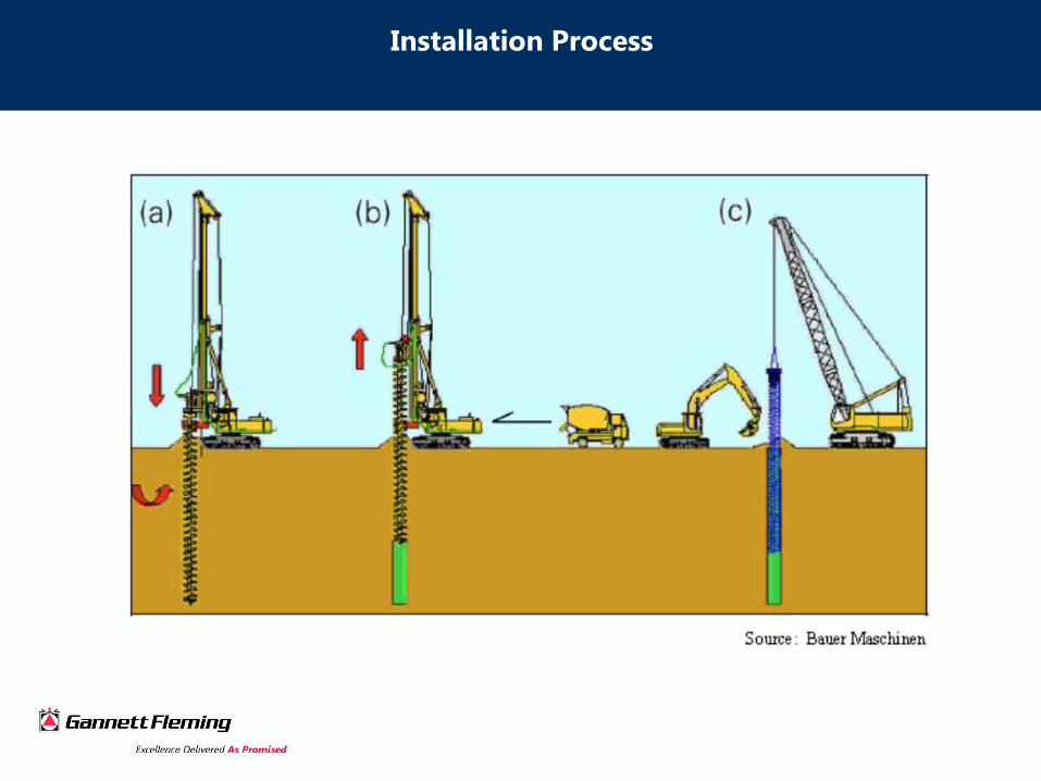
Installation Process
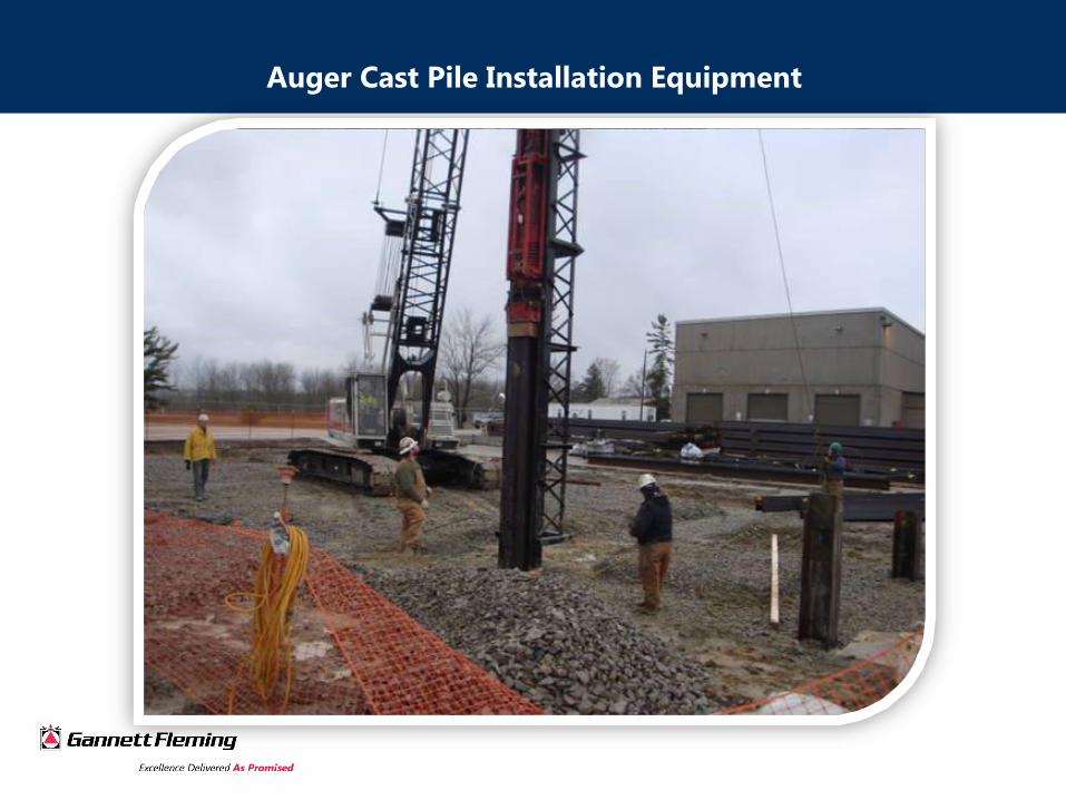
Auger Cast Pile Installation Equipment
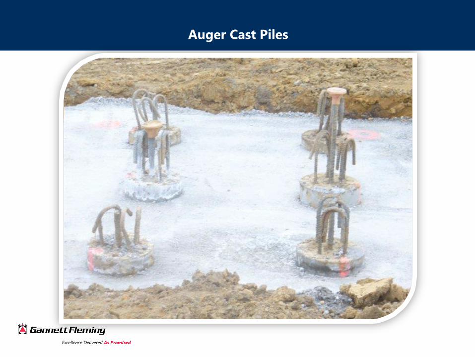
Auger Cast Piles
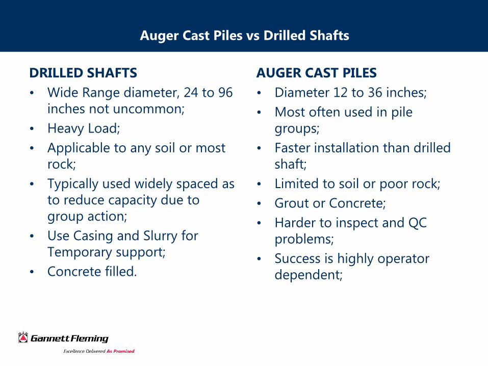
Auger Cast Piles vs Drilled Shafts
DRILLED SHAFTS
• Wide Range diameter, 24 to 96
inches not uncommon;
• Heavy Load;
• Applicable to any soil or most
rock;
• Typically used widely spaced as
to reduce capacity due to
group action;
• Use Casing and Slurry for
Temporary support;
• Concrete filled.
AUGER CAST PILES
• Diameter 12 to 36 inches;
• Most often used in pile
groups;
• Faster installation than drilled
shaft;
• Limited to soil or poor rock;
• Grout or Concrete;
• Harder to inspect and QC
problems;
• Success is highly operator
dependent;
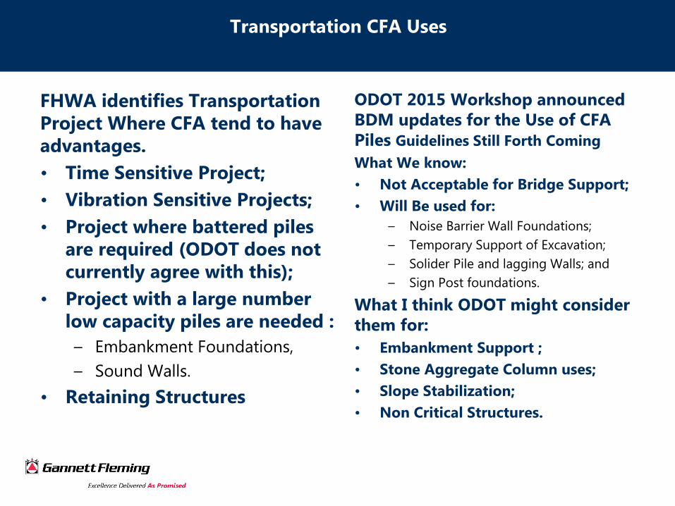
Transportation CFA Uses
FHWA identifies Transportation
Project Where CFA tend to have
advantages.
• Time Sensitive Project;
• Vibration Sensitive Projects;
• Project where battered piles
are required (ODOT does not
currently agree with this);
• Project with a large number
low capacity piles are needed :
– Embankment Foundations,
– Sound Walls.
• Retaining Structures
ODOT 2015 Workshop announced
BDM updates for the Use of CFA
Piles Guidelines Still Forth Coming
What We know:
• Not Acceptable for Bridge Support;
• Will Be used for:
– Noise Barrier Wall Foundations;
– Temporary Support of Excavation;
– Solider Pile and lagging Walls; and
– Sign Post foundations.
What I think ODOT might consider
them for:
• Embankment Support ;
• Stone Aggregate Column uses;
• Slope Stabilization;
• Non Critical Structures.
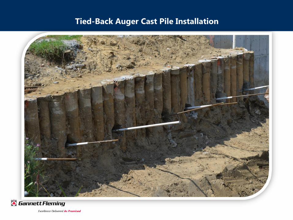
Tied-Back Auger Cast Pile Installation
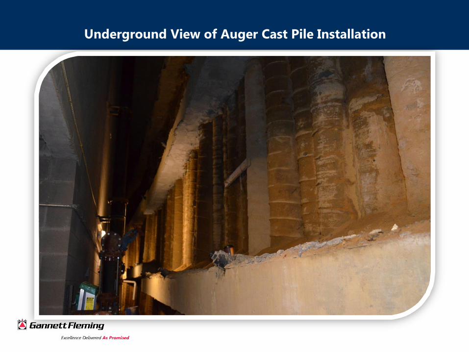
Underground View of Auger Cast Pile Installation
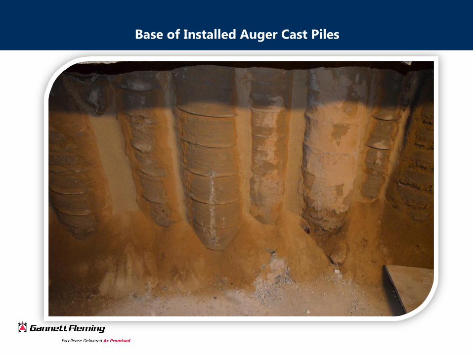
Base of Installed Auger Cast Piles

Watertight Excavation Support via Secant Auger Cast Pile Walls

Transportation CFA Uses
Traditional Concerns from FHWA about CFA piles
• No nationally accepted design protocol for CFA (static design
capacity);
• No national guideline specification for method and materials;
• No standards for quality control and assurance;
• No universally accepted standards for pile acceptance (static
load tests results).
Geotechnical Engineering Circular #8 Design and Construction of
Continuous Flight Auger Piles 2007
• Recommends Reese and O’Neil for Static Design and Settlement
• Provides Specifications for methods and materials; and
• Discusses Quality Control Measure.
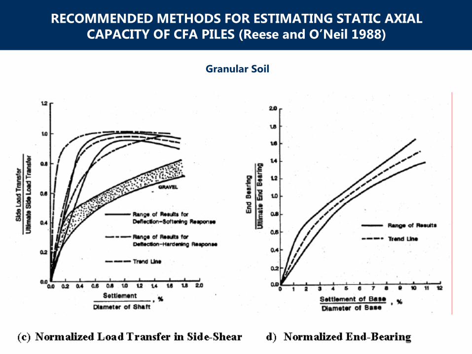
RECOMMENDED METHODS FOR ESTIMATING STATIC AXIAL
CAPACITY OF CFA PILES (Reese and O’Neil 1988)
Granular Soil
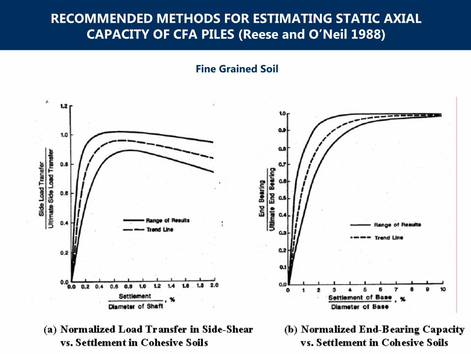
RECOMMENDED METHODS FOR ESTIMATING STATIC AXIAL
CAPACITY OF CFA PILES (Reese and O’Neil 1988)
Fine Grained Soil
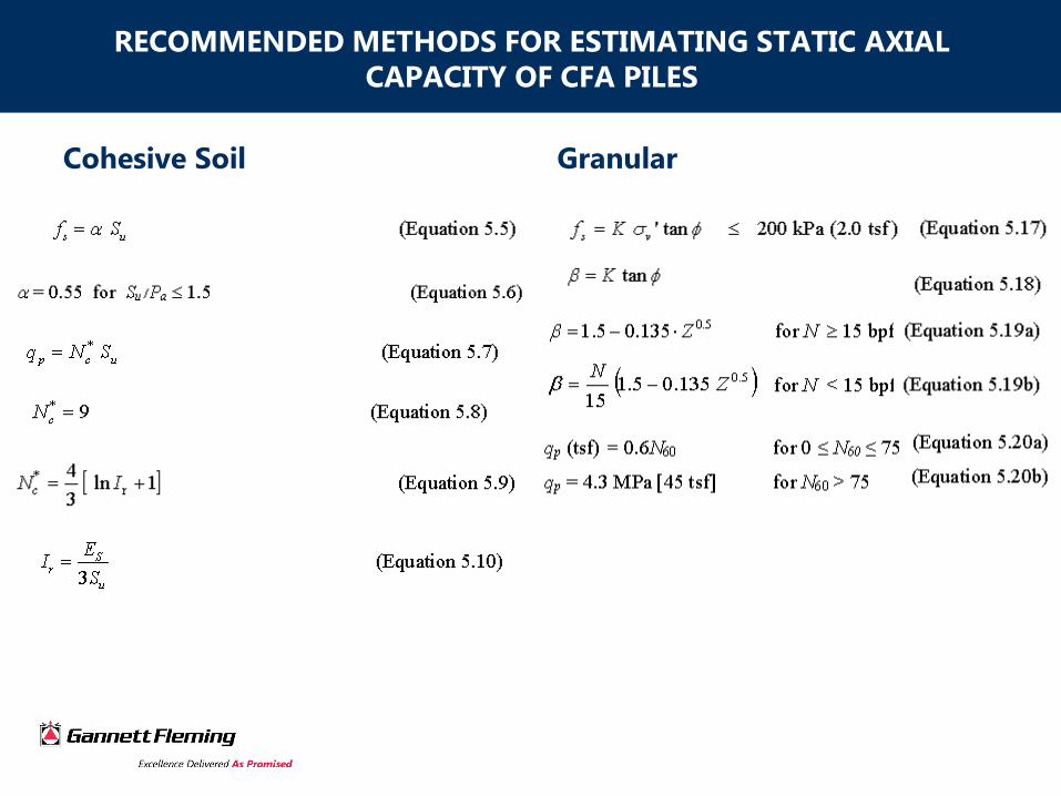
RECOMMENDED METHODS FOR ESTIMATING STATIC AXIAL
CAPACITY OF CFA PILES
Cohesive Soil Granular
Standards for Pile Appetence
Static Load Test
The static load test is the industry standard for pile testing. Advantages
of this system:
• Fast, inexpensive installation of reaction;
• Installing Contractor can perform test; and
• Relative light loading of CFA pile make testing practical.
Integrity Testing
• Pile Head Impact Testing (Sonic Echo Test, Sonic Mobility)
• Down the hole tests (Sonic Cross hole logging and Thermal Testing)
4.4 GEC 8
It is imperative that the demonstrated installation procedure be followed
for all production pile installations.
Limit States For Design
In general, there are three limit state conditions that must be satisfied
for design of CFA:
1. Geotechnical Ultimate Limit State (GULS). The pile should have a load
resistance that is greater than the expected loads (service loads) by an
adequate margin to provide a required level of safety (safety factor). For
axial compressive loads, the GULS is defined as the load resistance at a
displacement equal to 5% of the pile diameter in an axial static load test;
2. Service Limit State (SLS). The pile should undergo deformations at service
load levels that are within the tolerable limits appropriate for the structure.
The actual definition of the service limits should be determined by a rational
assessment of the sensitivity of the structure to deformations.
3. Structural Ultimate Limit State (SULS). The pile must have sufficient
structural capacity when the pile is subjected to combined axial and flexural
loads such that structural yielding of the pile is avoided. The SULS provides
a second definition of foundation strength.

The Davisson Criterion
The Davisson criterion, commonly used for driven piles, and shown for
reference in Figure 6.1, will sometimes underestimate the ultimate
resistance and is not appropriate for CFA piles.
Formula
0.150 in. + D/120 + PL/AE
D = Pile Diameter (inches)
L = Length of Pile (inches)
A= Area of Pile (inches2)
E = Modulus of Elasticity (psi) 1820√f’c
Adopted as the most conservative estimation of axial capacity based
on International Building Codes accepted methodologies.

Limit States For Design
Load Test
The Davisson Criterion
Shortcomings of the Davisson Offset Limit Applied to Axial
Compressive Load Tests on Cast-In-Place Piles
W. Morgan NeSmith, Member, Geo-Institute
Timothy C. Siegel, P.E., Member, Geo-Institute
1) The assumption that the cast-in-place pile behaves as a “fixed-base, freestanding
column.”
2) The assumption that an elastic line is a dependable reference line for interpretation of
load tests on cast-in-place piles. Kulhawy and Chen (2005) concluded that the DOL
assumptions tended to overestimate the stiffness of short piles and underestimate the
stiffness for longer piles.
3) In contrast, cast-in-place piles and other types of drilled piles do not compress the soil
beneath the pile toe during installation. Thus, a greater downward movement of the
pile toe would be required to mobilize the end resistance for cast-in-place piles if all
other conditions were equal.

Load Test Procedure
“Static Testing of Deep Foundations” (Kyfor et al., 1992) - FHWA-
SA-91-042;
“Design and Construction of Driven Pile Foundations,” Volumes 1
and 2 (Hannigan etal., 2006) - NHI Course FHWA-NHI-132021;
“Micropile Design and Construction” (Sabatini et al., 2005) - FHWA
NHI-05-039; and
“Drilled Shafts” (O’Neill and Reese, 1999) - FHWA-IF-99-025

Typical
Test pile Layout (Plan)

Typical
Test Pile Layout (Profile)

Typical
Load Test Configuration
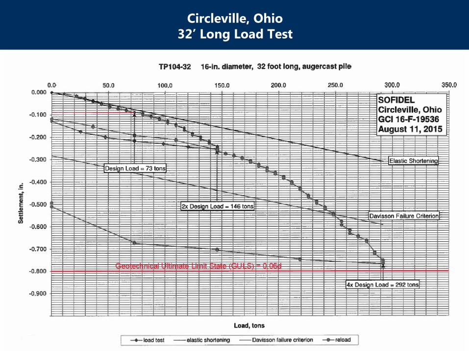
Circleville, Ohio
32’ Long Load Test
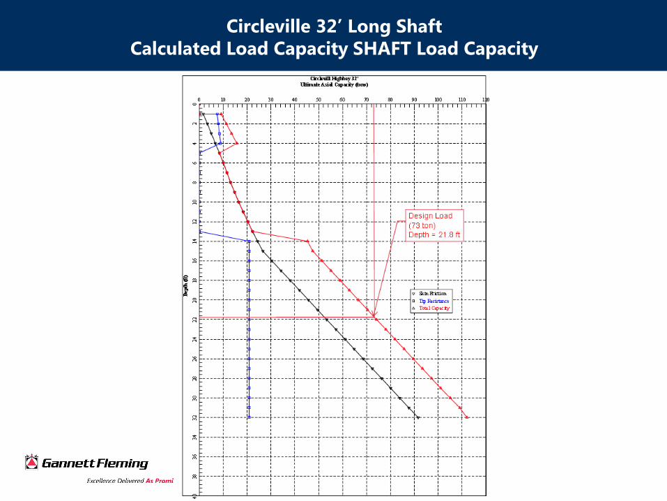
Circleville 32’ Long Shaft
Calculated Load Capacity SHAFT Load Capacity

Circleville 32’ Long Shaft
Calculated SHAFT Settlement

Circleville, Ohio
42’ Long Load Test
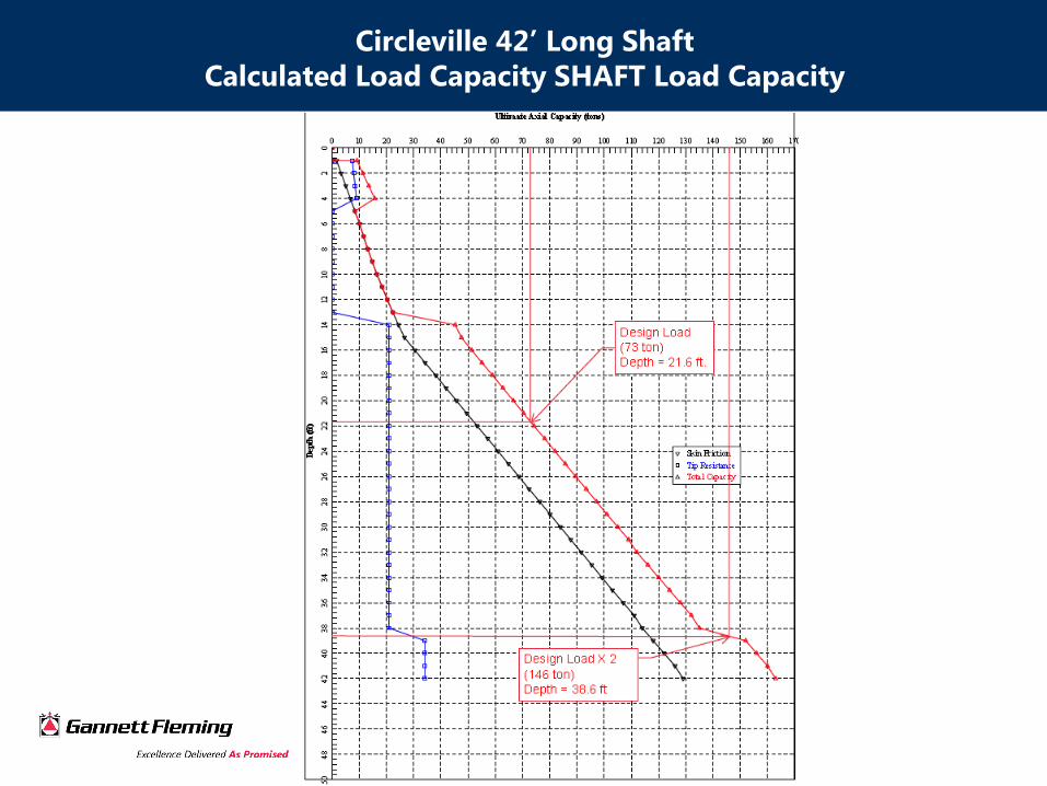
Circleville 42’ Long Shaft
Calculated Load Capacity SHAFT Load Capacity
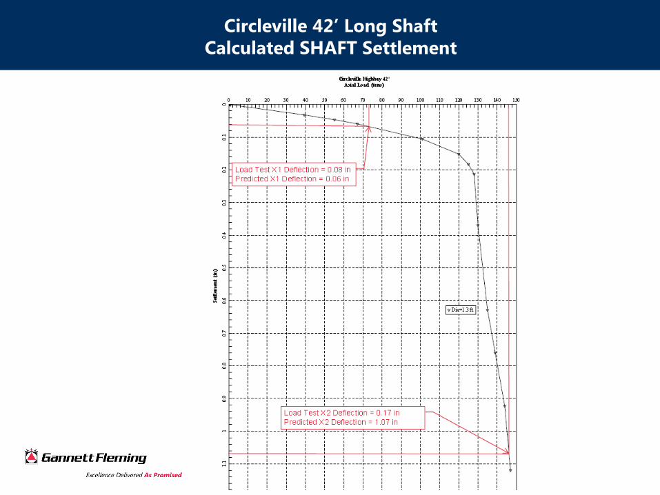
Circleville 42’ Long Shaft
Calculated SHAFT Settlement
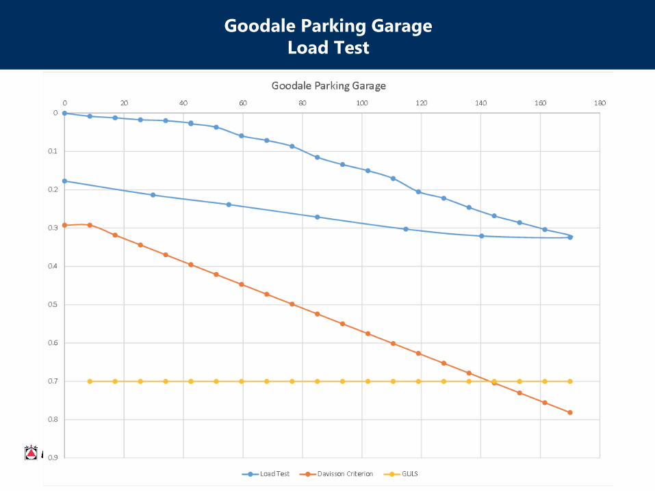
Goodale Parking Garage
Load Test

Goodale
Shaft Settlement Calculation
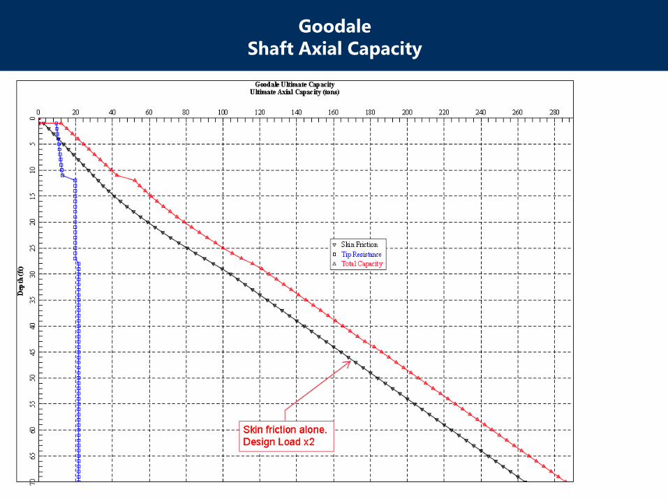
Goodale
Shaft Axial Capacity

Libbey Owens Ford
Load Test (1964)
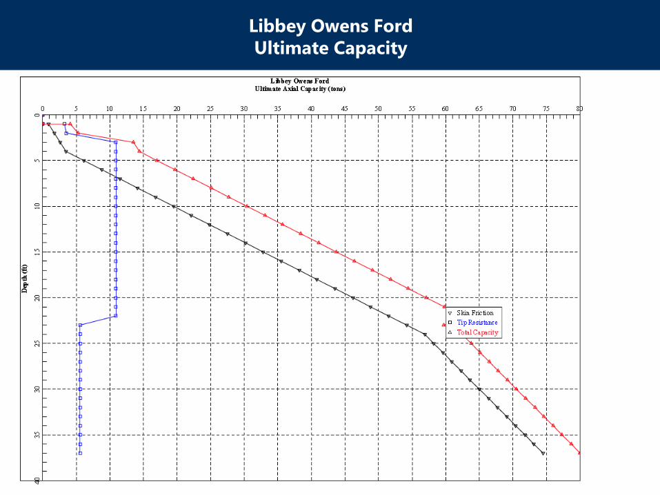
Libbey Owens Ford
Ultimate Capacity

Libbey Owens Ford
Settlement
Conclusion
1. Reese and O’Neil is acceptable for design of size and depth for a design load. Load
Tests verify that settlement and load capacity are accurately predicted at design loads.
2. A SF of 2.0 will generally result in the design capacity (Actual GULS) is typically higher
although settlement is actually often higher than SHAFT will predict at twice Design
load
3. SULS will often be achieved well before GULS (SULS = 0.4-0.25 f’c) Ohio building code
0.3 f’c
4. CFA piles tend to plunge (settle at tip) greater than drilled shafts possibly due to
smaller diameter than drilled shafts. This means when using CFA piles SLS should
closely looked at.
5. Davisson Criteria should not be the universal acceptance criteria for load tests as it is
too conservative for short piles and perhaps not conservative enough for very long
piles.

Thank You!
www.gannettfleming.com


