
© ABB Group
Relion. Thinking beyond the box.Designed to seamlessly consolidate functions, Relion relays are smarter, more flexible and more adaptable. Easy to integrate and with an extensive function library, the Relion family of protection and control delivers advanced functionality and improved performance.
This webinar brought to you by the Relion® product family Advanced protection and control IEDs from ABB
June 10, 2014 l Slide 1

© ABB Group
ABB is pleased to provide you with technical information regarding protective
relays. The material included is not intended to be a complete presentation of
all potential problems and solutions related to this topic. The content is
generic and may not be applicable for circumstances or equipment at any
specific facility. By participating in ABB's web-based Protective Relay School,
you agree that ABB is providing this information to you on an informational
basis only and makes no warranties, representations or guarantees as to the
efficacy or commercial utility of the information for any specific application or
purpose, and ABB is not responsible for any action taken in reliance on the
information contained herein. ABB consultants and service representatives
are available to study specific operations and make recommendations on
improving safety, efficiency and profitability. Contact an ABB sales
representative for further information.
ABB Protective Relay School Webinar SeriesDisclaimer
June 10, 2014 l Slide 2

© ABB Group
Input sources for protective relaysBharadwaj Vasudevan/ Elmo PriceJune 10, 2014
ABB Protective Relay School Webinar Series

© ABB Group
PresenterBharadwaj graduated from North Carolina State University with a Master of Science degree in Electrical Engineering. During his school days, he worked as a Research Assistant in the FREEDM Systems Center, designing and maintaining the labs’ automation infrastructure.
He began his career with Areva T&D Ltd in New Delhi, India as a Power Systems Engineer. He has worked on various EHV substation design projects throughout India. He was involved in the pilot project installation of 400kV Non conventional instrument transformer in Northern India.
Bharadwaj started at ABB as a consulting engineer for the Power systems group. With a strong background in real time power system modelling, he got to work on developing transient system models for a couple of transmission planning projects under the group.
He is currently working as an application engineer with the Power Systems Automation group for North America market. He supports all transmission level Relion relay products from Raleigh, NC. He is a member of the IEEE power system relay committee and contributes to various working groups in the relay communications subcommittees.
June 10, 2014 | Slide 4
Bharadwaj Vasudevan

© ABB Group
Learning objectives
What are Instrument Transformers ?
What are the application issues with voltage transformers ?
What are the application issues with CCVT’s ?
What are the application issues with current transformers ?
What are non conventional instrument transformers ?
June 10, 2014 | Slide 5

© ABB Group
Instrument transformer symbols
June 10, 2014 l Slide 6

© ABB Group
Purpose
Accurately reproduce primary voltage and current signals at secondary levels suitable for protective relays, meters, etc.
Provide secondary circuit isolation High voltage transients occurring on the primary
system Secondary circuit isolation
Design VTs are designed to minimize voltage magnitude
and phase angle error. Series leakage [and lead] losses are minimized
CTs are designed to minimize current magnitude and phase angle error. Magnetizing impedance is maximized.
June 10, 2014 l Slide 7

© ABB Group
Instrument transformer connections
June 10, 2014 l Slide 8

© ABB Group
Types of instrument transformers
Voltage transformation Electromagnetic voltage transformer Coupling capacitance voltage transformer Optical voltage transformer
Current transformation Electromagnetic current transformer Optical current transformer Rogowski coil
June 10, 2014 l Slide 9

© ABB Group
Voltage Transformers
June 10, 2014 l Slide 10

© ABB Group
Do not differ materially from constant-potential power transformers except Power rating is small Designed for minimum ratio &
phase angle error
Application limited to lower transmission and distribution voltages due to cost Full winding Cascade
Voltage transformer (VT/PT)
Inductive Voltage Transformer
June 10, 2014 l Slide 11

© ABB Group
Equivalent circuit of a VT
June 10, 2014 l Slide 12

© ABB Group
CCVTs are less expensive than inductive VTs at higher voltage level
Bases on capacitive coupling with low voltage inductive transformer
Subsidence transient issues due to capacitive and inductive response to system transient voltages (Zone–1 Overreach)
CCVT (CVT) - Coupling Capacitance Voltage Transformer
June 10, 2014 l Slide 13

© ABB Group
Simplified schematic of a CCVT
N:1
T
L
C2
C1
CFLF
RFActive
Ferroresonance Suppression
ZB
Primary
Secondary
LFRF
Passive Ferroresonance
Suppression ZB
Secondary
June 10, 2014 l Slide 14

© ABB Group
CCVT frequency response
104103102101
Frequency
0
-10
-20
-30
-40
-50
-60
Resp
onse
- dB
Active FSC
Passive FSC
June 10, 2014 l Slide 15

© ABB Group
Parameters that affect CCVT performance
Controlled by CCVT design Magnitude of tap and stack capacitance C1 and
C2
Turns ratio of the intermediate transformer T Type of ferroresonant suppression system
Controlled by user Magnitude and p.f. of the burden
At power system’s mercy Voltage transient characteristics
Point on voltage wave where the fault occurs Magnitude of voltage dip (fault inception voltage)
June 10, 2014 l Slide 16

© ABB Group
Transient response for today’s design
June 10, 2014 l Slide 17

© ABB Group
Parameter Small Transient
Large Transient
Magnitude of tap and stack capacitance C1 and C2 High Low
Turns ratio of the intermediate transformer T High Low
Type of ferroresonant suppression system Passive Active
Magnitude and p.f. of the burden Resistive Inductive
Parameters that affect CCVTPerformance
June 10, 2014 l Slide 18

© ABB Group
IEEE C57.13 accuracy class
June 10, 2014 l Slide 19

© ABB Group
Current Transformers
June 10, 2014 l Slide 20

© ABB Group
Current transformers
Current transformer primary connected in series with the line Primary current is determined
entirely by system load and not by CT secondary load
Free-standing BCT - bushing mounted
Internal
External
Bus and cable Ratio of transformation is
approximately inverse ratio of turns
June 10, 2014 l Slide 21

© ABB Group
Equivalent circuit of a CT
June 10, 2014 l Slide 22

© ABB Group
Current transformer
Secondary winding should never be open-circuited Flux in the core, instead of being the difference of
the primary & secondary ampere-turns, will now be due to the total primary ampere-turns acting alone
This causes a large increase in flux, producing excessive core loss & heating, as well as high voltage across the secondary terminals
At zero crossing of ac (60 Hz) flux large voltage spikes occur
June 10, 2014 l Slide 23

© ABB Group
Selection of CTs
Evaluating steady state performance Formula method
Excitation curves
ANSI accuracy classes
Transient performance
June 10, 2014 l Slide 24

© ABB Group
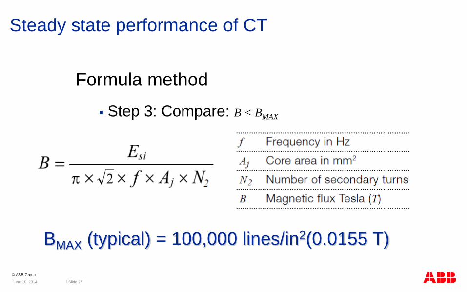
Steady state performance of CT
Formula method
Step 1: Determine voltage required to be supplied by the CT
June 10, 2014 l Slide 25

© ABB Group
Steady state performance of CT
Formula method Step 2: Determine voltage developed by the CT
June 10, 2014 l Slide 26
© ABB Group
Formula method
Step 3: Compare: B < BMAX
Steady state performance of CT
BMAX (typical) = 100,000 lines/in2(0.0155 T)
June 10, 2014 l Slide 27

© ABB Group
Excitation curves method Exciting current requirements for a
given secondary voltage
Current obtained by applying voltage to secondary terminals
Knee point Log-log plot
Square decades
I.e. (.01,1) – (.1,10)
Tangent 45º line
Steady state performance of CT
June 10, 2014 l Slide 28

© ABB Group
VS
Ie
IL
IH
Steady state performance of CT
1. Assume IL
2. VS = ILZT
ZT = ZL+ ZLead + ZB
3. With VS, find Ie from curve
4. IH = IL + Ie5. Repeat and plot IH vs. IL
curve
June 10, 2014 l Slide 29

© ABB Group
Steady state performance of CT
June 10, 2014 l Slide 30

© ABB Group
ANSI accuracy class
Relaying accuracy classes for CTs are defined with a “C” or “T” classification Class C indicates that the transformer ratio can
be calculated leakage flux is negligible The CT ratio error can thus be calculated The excitation characteristic can be used directly
to determine performance Class T indicates that the transformer ratio can
only be determined by test Leakage impedance is NOT negligible
June 10, 2014 l Slide 31

© ABB Group
ANSI accuracy class
Basis for classification Error ≤ 10% Current range 1 – 20 times normal
The classification defines how much voltage the CT can supply to the output (burden) without the CT core going into saturation Standard accuracy classes, which may be
assigned for a relaying CT, are 50, 100, 200, 400 and 800
June 10, 2014 l Slide 32

© ABB Group
IEEE C57.13 accuracy class
June 10, 2014 l Slide 33

© ABB Group
Steady State Performance of CT
1
10
100
1000
0.001 0.01 0.1 10 1001.0
10% error for 20 times rated secondary current (5 A)
VSM
VK
CT Ratio: 1200/5, RS (secondary winding resistance) = 0.61 Ω
What is C rating?VB(max) = VSM – 100 x RSVB(max) = 500 – 61 = 439 VSelect next lower rating level, C400VX = 400 V (saturation voltage)
500 V
230 V
Excitation voltage, VS = IS x (RS+ ZB)(operating maximums)
Saturation Factor, KS = VX/VS
Can this ct have a K class rating?
Rule: VK > 0.7 x VX
VX C400
Secondary Excitation Current, IE
Seco
ndar
y Ex
cita
tion
Volta
ge, V
S
June 10, 2014 l Slide 34

© ABB Group
ANSI accuracy classStandard chart for class C current transformers
June 10, 2014 l Slide 35

© ABB Group
CT Transients
June 10, 2014 l Slide 36

© ABB Group
Transients in power system
Faults on power system are sudden
Faults are accompanied by transients
These transients may last only for a few cycles of system frequency
Transients may effect the performance of fast- acting devices: protective relays, circuit breakers
June 10, 2014 l Slide 37

© ABB Group
D.C. saturation of a CT
Saturation of a CT may occur as a result of any one or combination of: Remnant (residual) flux in the core
Off-set fault currents (dc component)
June 10, 2014 l Slide 38

© ABB Group
Remnant Flux
Air Core Reactance
Magnetizing Reactance
Hysteresis Loop
Flux Density
Exciting Current - I
S
Results from hysteresis Depends largely on the
instantaneous flux in the core immediately prior to primary fault current (source of flux field) interruption
The remnant flux is also developed due to dc polarity test
Normal load current may reduce the amount of remnant flux, but not eliminate it.
Requires demagnetization
Remnant , φR
June 10, 2014 l Slide 39

© ABB Group
Remnant flux
To avoid saturation during a fault with the most unfavorable remnant flux requires about 3 times the core area otherwise needed when using a closed iron core
The remnant flux is also developed due to polarity test using battery (CT should be demagnetized following the test)
June 10, 2014 l Slide 40

© ABB Group
Core saturation effect in current
June 10, 2014 l Slide 41

© ABB Group
Remnant Flux and DC Offset
Avoiding Saturation
Steady state
Effect of primary DC offset
Effect of worst case saturation
SR
SS
X
SSX
SSX
RXZI
V
RXZIV
ZIV
ϕϕ−
+⋅
>
+⋅>
⋅>
1
1
1
June 10, 2014 l Slide 42

© ABB Group
Analyzing Transient Response of CT
Possibly sufficient time for relay operation prior to ct saturation
Time to Saturation
Possible maximum remnant flux
Level of fault current
System time constant
Parameters of ct and burden
factor saturationfault ofpoint toresistanceprimary fault ofpoint toreactanceprimary
frequency system is - 2
1
1ln
=====
−
−⋅−=
S
S
S
S
KRX
ffsaturatetotimet
RX
K
RXt
πω
ω
June 10, 2014 l Slide 43
© ABB Group
Protective relay designs to address CT issues
Most common issues
CT saturation
Open CT
Can be addressed in modern microprocessor relays
June 10, 2014 l Slide 44

© ABB Group
REB670 operating principles
Next slides will visualize the behavior of REB670 terminal during: Internal fault
External fault with CT saturation
Open CT condition
Disturbance occurs at sample No 41 on all of the following slides
June 10, 2014 l Slide 45

© ABB Group
Internal Fault
0
2
4
6
8
10
12
14
16
1 6 11 16 21 26 31 36 41 46 51 56 61 66 71 76 81
Samples
Curre
nt
i_ini_outI_INI_OUT
REB670 detects that I_IN goes up while I_OUT goes down at the beginning of the internal fault and enables fast tripping
When ID>Diff Operation Level
trip is issued
Quick operation for internal fault
June 10, 2014 l Slide 46

© ABB Group
External Fault with CT Saturation
0
2
4
6
8
10
12
14
16
1 4 7 10 13 16 19 22 25 28 31 34 37 40 43 46 49 52 55 58 61 64 67 70 73 76 79
Samples
Curre
nt
i_ini_outI_INI_OUT
REB670 detects that I_IN=I_OUT at the beginning of the
external fault
Proper and secure restraint REB670 detects this short interval when i_in=i_out(after every fault current
zero crossing) and restrain properly during
external fault
June 10, 2014 l Slide 47

© ABB Group
Open CT
0
0,2
0,4
0,6
0,8
1
1,2
1,4
1,6
1 5 9 13 17 21 25 29 33 37 41 45 49 53 57 61 65 69 73 77 81
Samples
Curre
nt
i_ini_outI_INI_OUT
REB670 detects that I_IN doesn't change while I_OUT goes down when some of the CTs are open/short circuited
ID>Open CT Levelsecond conditionfulfilled & RED is
blocked
Diff Operation LevelMust be set to higher value thanOpen CT Level
Fast open CT algorithm
June 10, 2014 l Slide 48

© ABB Group
New Sensor Technology
Non-traditional Instrument Transformers
June 10, 2014 l Slide 49

© ABB Group
New sensor technology
Traditional instrument transformers were required to meet the high power output requirements for electromechanical protection and control apparatus
Today’s modern digital IEDs and process bus communications do not require high power sensors
New sensor technologies are based on “old” proven concepts applied in new ways
New sensor technology offers: Reduced wiring costs Reduced weight Designed integration with primary system apparatus Immunity to electromagnetic interference Greatly improved accuracy
June 10, 2014 l Slide 50

© ABB Group
New sensor technology enables the digital substation
Types of new sensor technologies
Rogowski coils for current measurement
Fiber-optic current sensors
Provides digital signals to relays using IEC 61850-9-2LE
June 10, 2014 l Slide 51
IEC 61850 station bus
IEC 61850 process bus
Remote control
Supporting the digital substation architecture

© ABB Group
Rogowski coils
i(t)
v(t)
i(t)
v(t)
Primary conductor
Winding
Return wire loopSingle Arm Design
Series Two Arm Design
M
Data Converter IEDProcess Bus
dttdiMtv )()( −=
June 10, 2014 l Slide 52

© ABB Group
Rogowski coils
Advantages High measurement accuracy, from less than 1% to 3%
Wide measurement range, up to 100s of kA
Wide frequency range, typically 0.1 Hz to 1.0 MHz
Can withstand unlimited short circuit current
Can be physically small or large for application flexibility
Applicable at all voltage levels
June 10, 2014 l Slide 53

© ABB Group
Faraday Effect
Fiber-optic current sensor
June 10, 2014 l Slide 54

© ABB Group
Fiber-optic current sensor measuring principle
June 10, 2014 l Slide 55

© ABB Group
Fiber cable
Current
SF6 gas Circuit breaker
Sensor electronics
Sensing fiber coil
Fiber cable
Current
SF6 gas Circuit breaker
Sensor electronics
Sensing fiber coil
Conventional currentmeasurement
Circuit breakers
Fiber-optic current sensorApplied to 170kV live tank circuit breaker
June 10, 2014 l Slide 56

© ABB Group
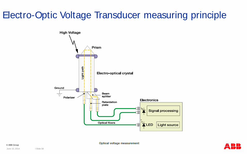
Electro-Optic Voltage Transducer
Electric field introduces refractive index difference for orthogonal light waves
Results in different speeds of light and differential phase shift
Electro-optic crystalBi4 Ge3 O12 (BGO)
y’
x’Orthogonal linearly
polarized light waves Phase shift proportional to applied voltage
∆φeo
∆φeo = c ⌡E.ds
Pockels effect
June 10, 2014 l Slide 57
© ABB Group
Electro-Optic Voltage Transducer measuring principle
June 10, 2014 l Slide 58

© ABB Group
Optical Metering Unit
Current transducer
Electro-optic effect in BGO crystal
Voltage transducer
Combines magneto-optic current transducer (MOCT) and electro-optic voltage transducer (EOVT)
Senses full line-to-ground voltage
Compact and lightweight
Ideal for addition of revenue metering to existing substations with limited space
High accuracy (class 0.2)
72 – 550 kV systems
Faraday effect in fused silica glass
OMU
Ground
High voltage
June 10, 2014 l Slide 59

© ABB Group
New sensor technology enables the digital substation
Hybrid solution can use conventional ITs and convert to digital process bus Utilize IEC 61850-9-2LE
with 80 samples/cycle for protection and operational metering
June 10, 2014 l Slide 60
IEC 61850 station bus
IEC 61850 process bus
Remote control
Supporting the digital substation architecture

© ABB Group
Hybrid Solution using a Merging Unit (MU)
June 10, 2014
SAM600-CT
Analog Signal Digital Signal
Low level signals in
the control house
control house
l Slide 61

© ABB Group
Standards
June 10, 2014 l Slide 62

© ABB Group
Standards
ANSI C93.1-1990 Power-Line Carrier Coupling Capacitors and
Coupling Capacitors and Coupling Capacitor Voltage Transformers (CCVT) – Requirements (http://www.ansi.org)
IEC 60186 (1987-01) (http://www.iec.ch) Voltage transformers (89 pp, Maintenance date 2000)
IEC 60044 : Refer different parts of the standard
June 10, 2014 l Slide 63

© ABB Group
Standards
ANSI/IEEE C57.13-1993 IEEE Standard Requirements for Instrument
Transformers (http://www.ansi.org)
IEEE C37.110-2007 Guide for the Application of Current
Transformers used for Protective Relaying (http://standards.ieee.org/)(http://standards.ieee.org/catalog/olis/relaying.html)
IEC 60044 – Refer different Parts (http://www.iec.ch/)
June 10, 2014 l Slide 64

© ABB Group
Conclusion
Conventional ITs CCVT’s are commonly used in HV and EHV relaying applications Transient response of the CCVT needs to be taken into
consideration Current transformer application needs to consider both static and
dynamic performance when sizing Time to saturation of a current transformer is an important criteria
in relaying Burden is a critical factor in CT selectionNon-Conventional ITs Non conventional instrument transformers avoid many of the
traditional concerns while improving safety and reliability GIS and AIS solutions available
Hybrid solution with MU offers path to digital substation
June 10, 2014 l Slide 65

© ABB Group
Relion. Thinking beyond the box.Designed to seamlessly consolidate functions, Relion relays are smarter, more flexible and more adaptable. Easy to integrate and with an extensive function library, the Relion family of protection and control delivers advanced functionality and improved performance.
This webinar brought to you by the Relion® product family Advanced protection and control IEDs from ABB
June 10, 2014 l Slide 66

© ABB Group
Thank you for your participation
Shortly, you will receive a link to an archive of this presentation.To view a schedule of remaining webinars in this series, or for more
information on ABB’s protection and control solutions, visit:
www.abb.com/relion
June 10, 2014 l Slide 67

© ABB Group
• Relion Series Relays – Advanced flexible platform for protection and control
• RTU 500 Series – Proven, powerful and open architecture
• MicroSCADA - Advanced control and applications
• Tropos – Secure, robust, high speed wireless solutions
This webinar brought to you by:ABB Power Systems Automation and Communication
We combine innovative, flexible and open products with engineering and project services to help our customers address their challenges.

© ABB Group


