
Relion. Thinking beyond the box.Designed to seamlessly consolidate functions, Relion relays aresmarter, more flexible and more adaptable. Easy to integrate andwith an extensive function library, the Relion family of protectionand control delivers advanced functionality and improvedperformance.
This webinar brought to you by the Relion® product familyAdvanced protection and control IEDs from ABB

ABB Protection Relay School Webinar SeriesDisclaimer
ABB is pleased to provide you with technical information regarding protective relays.
The material included is not intended to be a complete presentation of all potential
problems and solutions related to this topic. The content is generic and may not be
applicable for circumstances or equipment at any specific facility. By participating in ABB's
web-based Protective Relay School, you agree that ABB is providing this information to you
on an informational basis only and makes no warranties, representations or guarantees as
to the efficacy or commercial utility of the information for any specific application or
purpose, and ABB is not responsible for any action taken in reliance on the information
contained herein. ABB consultants and service representatives are available to study
specific operations and make recommendations on improving safety, efficiency and
profitability. Contact an ABB sales representative for further information.
© ABB Group

Symmetrical Components Examples& ApplicationPower System Fundamentals
ABB Protective Relay School Webinar Series, Michael Fleck, July 9, 2013

§© ABB Group
§July 9, 2013 | Slide 4
ProfileMichael Fleck, P.E.
Ø Regional Technical Manager, Midwest USAØ BSEE, Rose-Hulman Inst. of Technology, IndianaØ MSEE, Arizona State University, ArizonaØ Professional Engineer (P.E.), IndianaØ IEEE – Power & Energy Society MemberØ Experiences:ü ABB DA Regional Technical Manager, configuration of
products to meet customer applications, customertraining
ü Protection and Control Engineer, system modeling,control design, mentoring junior engineers for nationalconsulting company,
ü Transmission and Distribution P&C engineer, systemmodelling, system study, design, relay setting, troubleshooting for utility company

Learning Objectives
§ What we will discuss
§ Overview of converting phase quantities to symmetricalquantities and symmetrical to phase
§ Sequence Impedance networks – How do we build one?
§ Evaluating a Impedance network – Example Problem
§ Insights into the Example Problem
§ Why do we use this method?
§ Not using it would require writing loop equations for the systemand solving. – For simple systems it’s not an easy task
§ To date it is still the only real practical solution to problems ofunbalanced electrical circuits.
© ABB GroupJuly 9, 2013 | Slide 5

© ABB GroupJuly 9, 2013 | Slide 6
Symmetrical Components
§ The method of symmetrical components was discovered by DrCharles Fortescue while investigating problems of a singlephase railway system.
§ Introduced in 1918 in a classic AIEE transaction “Method ofSymmetrical Co-ordinates Applied to Solution of PolyphaseNetworks”.
§ The application to the analysis and operation of three phasepower systems was broadened by C. F. Wagner, R. D. Evansthrough a series of articles they published in the Westinghousemagazine “The Electric Journal” that ran from March 1928through November 1931

© ABB GroupJuly 9, 2013 | Slide 7
Symmetrical Components
§ Symmetrical Components is often referred to as the language ofthe Relay Engineer but it is important for all engineers that areinvolved in power.
§ The terminology is used extensively in the power engineeringfield and it is important to understand the basic concepts andterminology.
§ Used to be more important as a calculating technique before theadvanced computer age.
§ Is still useful and important to make sanity checks and back-of-an-envelope calculation.

© ABB GroupJuly 9, 2013 | Slide 8
Symmetrical components and faultanalysisVoltage & Current Conversion Review

© ABB GroupJuly 9, 2013 | Slide 9
Symmetrical Components
§ Balanced load supplied by balanced voltage results in balancedcurrent.
i. This situation results in only positive sequencecomponents
ii. Seldom achievable in real world applications
§ Positive Sequence currents produce only positive sequencevoltages, Negative sequence currents produce only negativesequence voltages, and zero sequence currents produce onlyzero sequence voltages
§ For unbalanced systems: Positive Sequence currents producepositive, negative and sometimes zero sequence voltages,Negative sequence currents produce positive, negative andsometimes zero sequence voltages, and zero sequence currentsproduce positive, negative, and zero sequence voltages

Symmetrical Components
§For the General Case of 3 unbalanced voltages
§VA
§VB
§VC§6 degrees of freedom
§Can define 3 sets of voltages designated as positivesequence, negative sequence and zero sequence
© ABB GroupJuly 9, 2013 | Slide 10
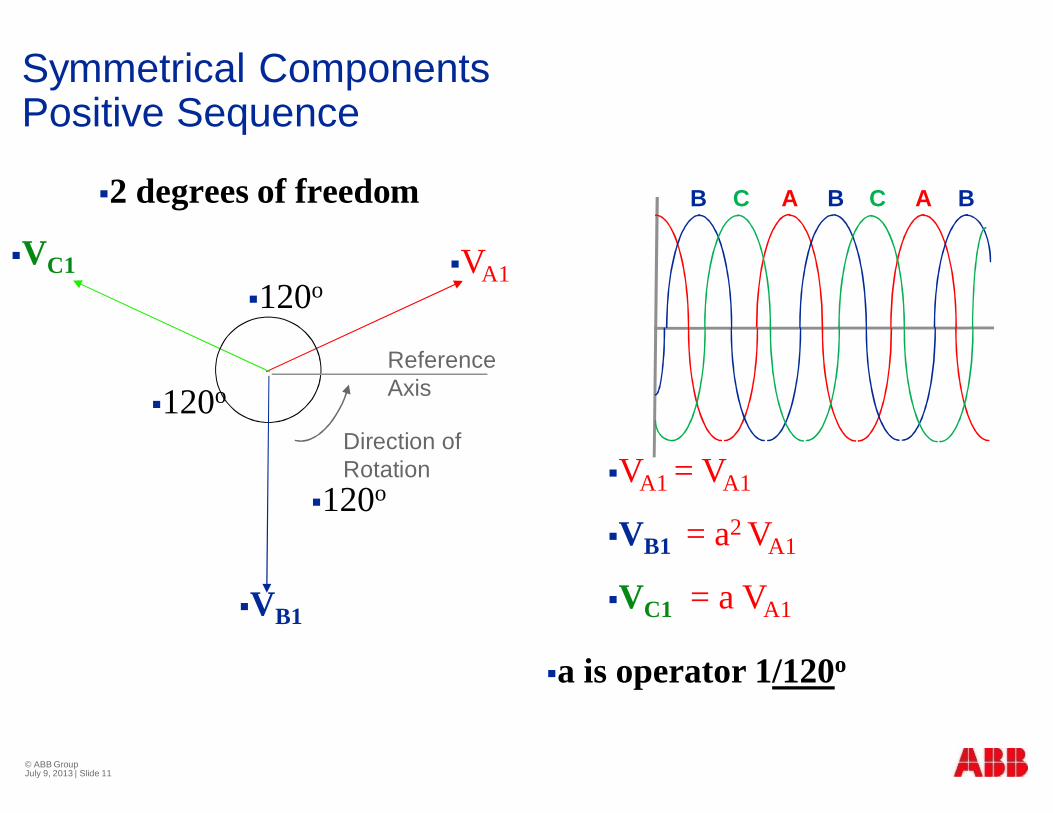
Symmetrical ComponentsPositive Sequence
§120o
§120o
§120o
§VA1
§VB1
§VC1
§2 degrees of freedom
§VA1 = VA1
§VB1 = a2 VA1
§VC1 = a VA1
§a is operator 1/120o
ReferenceAxis
Direction ofRotation
B CA BB C A
© ABB GroupJuly 9, 2013 | Slide 11

Symmetrical ComponentsNegative Sequence
§120o
§120o
§120o
§VA2
§VC2
§VB2
§2 degrees of freedom
§a is operator 1/120o
§VA2 = VA2
§VB2 = aVA2
§VC2 = a2 VA2
ReferenceAxis
Direction ofRotation
BCA CBC A
© ABB GroupJuly 9, 2013 | Slide 12

Symmetrical ComponentsZero Sequence
§2 degrees of freedom
§VA0§VB0§VC0
§VA0 = VB0 = VC0
ABC ABC
© ABB GroupJuly 9, 2013 | Slide 13
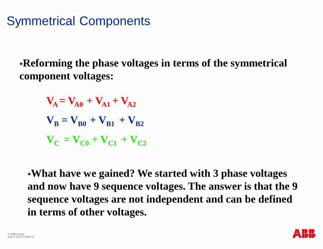
Symmetrical Components
§Reforming the phase voltages in terms of the symmetricalcomponent voltages:
VA = VA0 + VA1 + VA2
VB = VB0 + VB1 + VB2
VC = VC0 + VC1 + VC2
§What have we gained? We started with 3 phase voltagesand now have 9 sequence voltages. The answer is that the 9sequence voltages are not independent and can be definedin terms of other voltages.
© ABB GroupJuly 9, 2013 | Slide 14
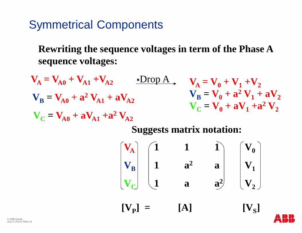
Symmetrical Components
Rewriting the sequence voltages in term of the Phase Asequence voltages:
VA = VA0 + VA1 +VA2
VB = VA0 + a2 VA1 + aVA2
VC = VA0 + aVA1 +a2 VA2
VA = V0 + V1 +V2VB = V0 + a2 V1 + aV2VC = V0 + aV1 +a2 V2
§Drop A
Suggests matrix notation:
VA 1 1 1 V0
VB 1 a2 a V1
VC 1 a a2 V2
[VP] = [A] [VS]© ABB GroupJuly 9, 2013 | Slide 15

Symmetrical Components
[VP] = Phase Voltages
[VS] = Sequence Voltages
1 1 1
[A] = 1 a2 a
1 a a2
[VP] = [A][VS]
Pre-multiplying by [A]-1
[A]-1[VP] = [A]-1[A][VS]= [I][VS]
[VS] = [A]-1 [VP]
1 1 1
[A]-1 =1/3 1 a a2
1 a2 a
[VS] = [A]-1[VP]
© ABB GroupJuly 9, 2013 | Slide 16

© ABB GroupJuly 9, 2013 | Slide 17
Symmetrical components & FaultAnalysisImpedance Networks

© ABB GroupJuly 9, 2013 | Slide 18
Symmetrical Components
Typical System Parameter used in Symmetrical ComponentAnalysis
§ Transmission Lines
§ Transformers
§ Generators

Transmission LineImpedance
§ Size and type of phase andground conductors
§ Geometric configuration of thetransmission line
§ Transpositions over the length ofthe line
§ Shunt capacitance is generallyneglected for fault studies
HG
HA
§DBC
A B C
G G
Symmetrical Components – Line Constants
© ABB GroupJuly 9, 2013 | Slide 19

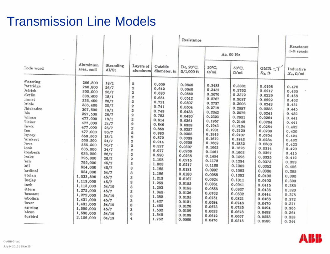
Transmission Line Models
The general models for transmission lines
Positive and Negative Sequence
§Zero Sequence
r1 + j x1
r0 + j x0
© ABB Group
July 9, 2013 | Slide 20

Transmission Line Models
Positive & Negative Sequence ( Z1 = Z2)
§ Z1 = R1 + jX1
§ R1 = r/n for n conductors per phase:
§ r can be found in lookup tables showing cableresistance
Note skin effect: rdc< r60Hz
§ X1 can be found from the general equation for inductance
SL
EQ
DD
xL ln102 7
1
-= Henries/meter
© ABB Group
July 9, 2013 | Slide 21

Transmission Line Models
SL
EQ
DD
fLX ln1213.2 11 == p Ω per mile for 60 Hz
31
)( cabcabEQ DDDD ´´=
b
a
c
Dab
DcaDbc
This assumes transpositionbut is reasonably accurateif not transposed.
© ABB Group
July 9, 2013 | Slide 22

Transmission Line Models
For a 1-conductor bundle:
For a 2-conductor bundle:
For a 3-conductor bundle:
For a 4-conductor bundle: 4 3091.1 dgmrDSL ´´=
dgmrDSL ´=
3 2dgmrDSL ´=
gmrDSL =
How to calculate DSL
If there are n conductors per phase, DSL is the distance from everyconductor in the bundle to every other conductor to the 1/n2
§For 3 conductor bundle [ ] 91
))()()()()()()()(( ddgmrdgmrdgmrddDSL =
[ ] 312)( dgmrDSL =
© ABB Group
July 9, 2013 | Slide 23

Transmission Line Models
Example:
Find the positive sequence model for 20 mile of transmission line with 2-conductor bundle 2156 KCM ACSR Conductors (Bluebird) and the followingconductor configuration:
Found from cable lookup table:
Diameter = 1.762 in. Radius = 0.881 in. = 0.0734 ft.
gmr = 0.0586 ft. Resistance = 0.0515 Ω/mile
Find: Positive and Negative Sequence Impedance for a 20 mile line
o o o o o o
18”
30 ft 30 ft
© ABB Group
July 9, 2013 | Slide 24
Transmission Line Models
© ABB Group
July 9, 2013 | Slide 25
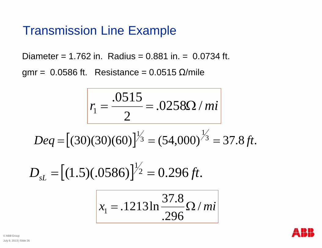
Transmission Line Example
mir /0258.2
0515.1 W==
[ ] .8.37)000,54()60)(30)(30( 31
31
ftDeq ===
[ ] .296.0)0586)(.5.1( 21
ftDsL ==
Diameter = 1.762 in. Radius = 0.881 in. = 0.0734 ft.
gmr = 0.0586 ft. Resistance = 0.0515 Ω/mile
mix /296.
8.37ln1213.1 W=
© ABB Group
July 9, 2013 | Slide 26

§27
Transmission Line Example
lengthLinexrZZ )( 1121 +==
o57.8781.118.1152.021 Ð=W+== jZZ
o57.8781.11 Ð
© ABB Group
July 9, 2013 | Slide 27

Transmission Line Models Z0
© ABB Group
July 9, 2013 | Slide 28
§ If Ia + Ib + Ic ≠ 0 there will be neutral current flow
§ If the neutral is grounded all of part of the neutral current willflow in the ground
§ Need to determine the impedance to the flow of this current:Z0
§ Made possible by Carson’s work which shows that earth canbe modeled by one or more equivalent conductors
§ We will use one equivalent conductor below the earth’ssurface for each real conductor.

Transmission Line Models Z0
Just one OHGW to simplify work but showing principal
Earth Surface
a
a’
b
b’
c
c’
n
n’

§30
Transmission Line Models Z0 – Carson’s Formula
kkkk DD =''
fDkkr5.658' =
= gmr of the overhead conductor
Meters
fRk7
' 10869.9 -*= Ohms / meter
where: f = frequency in Hz
ρ = earth resistively in ohm-meters
Transmission Line Models – Z0
Z0 is much more difficult to find and depend on:
§ Ground resistance
§ Conductor height above ground
§ Distance from phase conductors to
overhead ground wires (OHGW)
§ Characteristics of OHGW
§ Z0 > Z1 due to mutual coupling between phases.Mutual coupling to adjacent circuits must beconsidered
§ Rule of Thumb: 2Z1< Z0 < 4Z1
© ABB Group
July 9, 2013 | Slide 31

§ Factors to Consider
§ Polarity
§ Three Phase Connections
§ Number of Windings
§ Core Design
Transformer Constants
© ABB GroupJuly 9, 2013 | Slide 32

Transformer Models
Positive and Negative Sequence Connections
Zero Sequence
jX1 = jX2 =jX0
Dependant on Transformer winding connections
© ABB Group
July 9, 2013 | Slide 33
The general models for transformer lines
The one exception to this is when we have a three phase core-type transformer

Transformer Connections for ZeroSequence
L H
Ic IaIb
IC IAIB
L H
Ia + Ib + Ic is not necessarily 0 if we only look at Low Voltage circuit
But we know IL = nIH : Ia = nIA Ib = nIB and Ic = nICSince IA + IB + IC = 0 , Ia + Ib + Ic = 0 and I0 = 0
L0 H0Z0 = ZL+ ZH
n0
No zero sequence currentflow through transformer
n:1
© ABB Group
July 9, 2013 | Slide 34

Transformer Connections for Zero Sequence
L H
Ic IaIb
IC IAIB
L H
Ia + Ib + Ic is not necessarily 0 and IA + IB + IC is not necessarily.
L0 H0
n0
I0 can flow through the transformer.Therefore I0 is not necessarily 0,
I0
n:1
© ABB Group
July 9, 2013 | Slide 35
Z0 = ZL+ ZH

Transformer Connections for Zero Sequence
L H
Ic IaIb IC
IA
IB
L H
Ia + Ib + Ic is not necessarily 0 and IA/n + IB/n + IC/n is not necessarily 0
L0 H0
n0
§Provides a zero sequence current source
IB/n
IC/n
IA/n
I0
But IA + IB + IC = 0
n:1
© ABB Group
July 9, 2013 | Slide 36
Z0 = ZL+ ZH

Transformer Connections for ZeroSequence
L H
Ic IaIb IC
IA
IB
L H
Ia + Ib + Ic = 0 IA/n + IB/n + IC/n is not necessarily 0, but IA + IB + IC = 0
L0 H0
n0
§No zero sequence current flow
IB/n
IC/n
IA/n
n:1
© ABB Group
July 9, 2013 | Slide 37
Z0 = ZL+ ZH

Transformer Connections for Zero Sequence
L H
IC
IA
IB
L H
Ia + Ib + Ic = 0 IA + IB + IC = 0
L0 H0Z0
n0
No zero sequence current flow
Δ ΔIa
Ib
Ic
© ABB Group
July 9, 2013 | Slide 38
n:1

Rotating Machine Sequence Networks
A
B
C
ZK
ZK
ZK
-
- -
+
+ +
EB
EAEC
IC
IA
IB
Zn
ZAB
ZBC
ZCA
ZCB
ZBA
ZAC
eA = Em Cos ωteB = Em Cos(ωt – 120o)e
C = Em Cos(ωt + 120o)
In phasor form:EA= ERMS / 0 = EEB = ERMS /-120o = a2 EEC = ERMS /120o = a E
§© ABB Group
§July 9, 2013 | Slide 39

Rotating Machine Sequence Networks
[ ]úúú
û
ù
êêê
ë
é=
aEEa
EEPg
2EA= ERMS / 0 = EEB = ERMS /-120o = a2 EEC = ERMS /120o = a E
or
[ ] [ ] [ ]úúú
û
ù
êêê
ë
é=
úúú
û
ù
êêê
ë
é
úúú
û
ù
êêê
ë
é== -
0
0
11
111
31 2
2
21 EaE
EaE
aaaaEAE PgSg
§Therefore, only the positive sequence system has agenerator voltage source.
0
1
2
a
b
c
© ABB Group
July 9, 2013 | Slide 40

Rotating Machine Sequence Networks§Generator sequence circuits are uncoupled
3Zn
ZG0 I0
V0
EG1
-
+ ZG1 I1
V1
ZG2 I2V2
GeneratorTerninalVoltages
© ABB Group
July 9, 2013 | Slide 41

Internal Machine Voltages and Reactances
E”E’Ed
Xd” Xd’ Xd
§Et
Xd” - Subtransient Reactance
Xd’ - Transient Reactance
Xd - Synchronous Reactance
Symmetrical Components– Gen Constants
© ABB GroupJuly 9, 2013 | Slide 42

© ABB GroupJuly 9, 2013 | Slide 43
Example ProblemA Generator is connected to a power system through a 22kV delta to 230kVgrounded wye transformer rated at 100MVA and with a series reactance of0.14pu. The generator is rated at 100MVA and 22kV and has X’’d =X2 =0.16pu. The generator neutral is not grounded. A bolted single line to groundfault occurs at 50 miles down the line on the 230kV terminals of the transformeron Phase A. Assume transmission line is the same 2156KCM Bluebirdconductor and arrangement, which was evaluated earlier
Find:
The fault current in Phase a, b, and c in pu and primary current
The phase voltages at the point of the fault in pu and primary voltage
The fault current in Phase a, b, and c in pu and primary current on 22kV side
S = 100MVA
Xd’’ =X2= 0.16pu
S = 100MVA
X1=X2=0.141P-GND FAULT
V = 22kV V = 22kV V = 230kV
50 Miles Bluebird

© ABB GroupJuly 9, 2013 | Slide 44
Example ProblemFind:
The fault current in Phase a, b, and c in pu and primary values
S = 100MVA
Xd’’ =X2= 0.16pu
S = 100MVA
X1=X2=0.14
V = 22kV V = 22kV V = 230kV
50 Miles Bluebird
Found earlier that Bluebird conductor characteristics at 60Hz was
mir /0258.2
0515.1 W== mix /
296.8.37ln1213.1 W=
1P-GND FAULT

© ABB GroupJuly 9, 2013 | Slide 45
Example ProblemFind:
The fault current in Phase a, b, and c in pu and primary values
S = 100MVA
Xd’’ =X2= 0.16pu
S = 100MVA
X1=X2=0.14
V = 22kV V = 22kV V = 230kV
50 Miles Bluebird
W+´= )59.00258.0(5050 jZ MILES
1P-GND FAULT
W=== 52910023022
BASE
BASEBASE MVA
kVZ
pujZ MILESPUo5.87056.0
52941.2929.1
50 Ð=W+
=

© ABB GroupJuly 9, 2013 | Slide 46
Example ProblemFind:
The fault current in Phase a, b, and c in pu and primary values
S = 100MVA
Xd’’ =X2= 0.16pu
S = 100MVA
X1=X2=0.14
V = 22kV V = 22kV V = 230kV
50 Miles Bluebird
1P-GND FAULT
Create our Positive and Negative Sequence networks
Positive
X1= j0.16 X1= j0.14 [email protected]
N1

© ABB GroupJuly 9, 2013 | Slide 47
Example ProblemFind:
The fault current in Phase a, b, and c in pu and primary values
S = 100MVA
Xd’’ =X2= 0.16pu
S = 100MVA
X1=X2=0.14
V = 22kV V = 22kV V = 230kV
50 Miles Bluebird
1P-GND FAULT
Create our Positive and Negative Sequence networks
X2= j0.16 X2= j0.14 [email protected]
Negative
N2

© ABB GroupJuly 9, 2013 | Slide 48
Example ProblemFind:
The fault current in Phase a, b, and c in pu and primary values
S = 100MVA
Xd’’ =X2= 0.16pu
S = 100MVA
X1=X2=0.14
V = 22kV V = 22kV V = 230kV
50 Miles Bluebird
1P-GND FAULT
§Create Zero Sequence, For Simplicity Assume Z0 = 3 x Z1 for Transmission Line
§Zero Sequence configuration for a transformer that is delta grounded wye is shown
once again below.
§Remembering this we Can Draw the Zero Sequence network for this problem
L0 H0Z0
n0
I0

© ABB GroupJuly 9, 2013 | Slide 49
Example ProblemFind:
The fault current in Phase a, b, and c in pu and primary values
S = 100MVA
Xd’’ =X2= 0.16pu
S = 100MVA
X1=X2=0.14
V = 22kV V = 22kV V = 230kV
50 Miles Bluebird
1P-GND FAULT
N0
X0=j0.14 [email protected]
Zero Sequence

© ABB GroupJuly 9, 2013 | Slide 50
Example ProblemFind:
The fault current in Phase a, b, and c in pu and primary values
S = 100MVA
Xd’’ =X2= 0.16pu
S = 100MVA
X1=X2=0.14
V = 22kV V = 22kV V = 230kV
50 Miles Bluebird
1P-GND FAULT
Positivef1
N1
Z1=j0.356
Negative
N2
f2
Z2=j0.356
N0
Zero Sequence
f0

© ABB GroupJuly 9, 2013 | Slide 51
Example Problem
Z1
Z0
Z2
Positive
Zero
Negative
EA1 e j0 IA1
IA2
IA0
VA1
VA2
VA0
o
o
7.88307.0356.0356.001
Ð++Ð
==jjZ
VIPU
PUPU
puIPUo6.891 -Ð=
[IP] = [A][IS]
1 1 1 -j1
[IP] = 1 a2 a -j1
1 a a2 -j1
-j3 A
[IP] = 0 B
0 Cpu

© ABB GroupJuly 9, 2013 | Slide 52
Example Problem
Axx
xV
SIBASE
BASEBASE 251
10230310100
3 3
6
===
-j753A A
[IP] = 0 B
0 C
The phase voltages at the point of the fault
V 0 0 j0.307 0 0 -j1 -0.307
V 1 = 1 - 0 j0.356 0 -j1 = 0.644
V 2 0 0 0 j0.356 -j1 -0.356
Z1
Z0
Z2
Positive
Zero
Negative
EA1 e j0 IA1
IA2
IA0
VA1
VA2
VA0
Actual

© ABB GroupJuly 9, 2013 | Slide 53
Example Problem
The phase voltages at the point of the fault
V 0 0 j0.307 0 0 -j1 -0.307
V 1 = 1 - 0 j0.356 0 -j1 = 0.644
V 2 0 0 0 j0.356 -j1 -0.356
[VP] = [A][VS]1 1 1 -0.307 0
[VP] = 1 a2 a 0.644 = [email protected]
1 a a2 -0.356 [email protected]
PUBASEPHASE VVV ´=
0 A
[VP] = [email protected] kV B
[email protected] kV C
Actual
pu

© ABB GroupJuly 9, 2013 | Slide 54
Phase Quantities Symmetrical Components
VA
VC VB
IA
IB
ICqf
IA1
IA2
3IA03V0
VA2
VA1
Phase-to-ground Fault

© ABB GroupJuly 9, 2013 | Slide 55
GG
VA1 VA1V1(f-g) 2/3VA1
V2(f-g)
V0(f-g)-1/3VA1
These magnitudes assume Z1 = Z2 = Z0
Phase-to-ground Fault Voltage Profile

© ABB GroupJuly 9, 2013 | Slide 56
Example ProblemThe fault current in Phase a, b, and c in pu and primary current on 22kV side
S = 100MVA
Xd’’ =X2= 0.16pu
S = 100MVA
X1=X2=0.141P-GND FAULT
V = 22kV V = 22kV V = 230kV
50 Miles Bluebird
[IP] = [A][IS]
Found Earlier our phase and sequence quantities in pu on the 230kV side ofTransformer
Knowing this information we can find Phase currents on the 22kV side ofTransformer
-j1 Zero
[ISprimary] = -j1 Positive
-j1 Negative

© ABB GroupJuly 9, 2013 | Slide 57
Example ProblemThe fault current in Phase a, b, and c in pu and primary current on 22kV side
S = 100MVA
Xd’’ =X2= 0.16pu
S = 100MVA
X1=X2=0.141P-GND FAULT
V = 22kV V = 22kV V = 230kV
50 Miles Bluebird
0 Zero
[ISsecondary] = 1@-120 Positive
1@-60 Negative
Looking back Zero Sequence current has no path to flow on the 22kV side
How do these differ from currents on the 230kV side?

© ABB GroupJuly 9, 2013 | Slide 58
Example ProblemThe fault current in Phase a, b, and c in pu and primary current on 22kV side
1 1 1 0 1.73@-90
[IPsecondary] = 1 a2 a 1@-120 = 1.73@90
1 a a2 1@-60 0
-j4540A A
[IPsecondary] = j4540A B
0 C
pu
Actual
4540322
220753sec_ == kV
kVxI act
Ic Ia =753AIb
nIb
nIc
nIa
1:n
IA =4540A
Axx
xxV
SIBASE
BASEbase 2624
1022310100
3 3
6
===

© ABB GroupJuly 9, 2013 | Slide 59
Example ProblemThe fault current in Phase a, b, and c in pu and primary current on 22kV side
S = 100MVA
Xd’’ =X2= 0.16pu
S = 100MVA
X1=X2=0.141P-GND FAULT
V = 22kV V = 22kV V = 230kV
50 Miles Bluebird
1 1 1 0 4540@-90
[IPsecondary] = 1 a2 a 1@-120 = 4540@90
1 a a2 1@-60 0What has this taught us?
-j753A A
[IPprimary] = 0 B
0 CActual
Actual

© ABB GroupJuly 9, 2013 | Slide 60
Phase-to-phase Fault
VA
VC VB
IB
IC
qf
Phase Quantities Symmetrical Components
3VA1
VBC
VA
a2VC
aVB
3VA2
a2VB
aVC
3IA1
3IA2
a2 IC
a2 IB
aIB
aIC
VA

© ABB GroupJuly 9, 2013 | Slide 61
Waveforms from SLG fault

© ABB GroupJuly 9, 2013 | Slide 62
Symmetrical Components Learned Objectives
§ What we will discuss
§ Overview of converting phase quantities to symmetricalquantities and symmetrical to phase
§ Sequence Impedance networks – How do we build one?
§ Evaluating a Impedance network – Example Problem
§ Insights into the Example Problem
§ Why do we use this method?
§ Not using it would require writing loop equations for the systemand solving. – For simple systems it’s not an easy task
§ To date it is still the only real practical solution to problems ofunbalanced electrical circuits.

© ABB GroupJuly 9, 2013 | Slide 63

Thank you for your participation
Shortly, you will receive a link to an archive of this presentation.To view a schedule of remaining webinars in this series, or for more
information on ABB’s protection and control solutions, visit:
www.abb.com/relion
© ABB GroupJuly 9, 2013 | Slide 64


