
Harvard-SmithsonianCenter for Astrophysics
MMIRS PDR (Thermal)
Thermal Design and Analysis
Sang ParkThermal Engineer
July 6th, 2004
sp 1

Harvard-SmithsonianCenter for Astrophysics
MMIRS PDR (Thermal)
Agenda• Camera Section
– Requirements– Thermal Design– Operational Profile (hold time, observation)– Optical Bench– Optical Assembly– Thermal Math Model – Cooling profile– Lens temperature profiles
• MOS Section– Thermal Design– Operational Profile (Transition time, Hold time)
• Planned Activities
sp 2

Harvard-SmithsonianCenter for Astrophysics
MMIRS PDR (Thermal)
Camera Section
sp 3

Harvard-SmithsonianCenter for Astrophysics
MMIRS PDR (Thermal)
Optical Assembly
Optical Assembly:• Lens Temperature Gradient
Requirements (degrees C):
sp 4
Harvard-SmithsonianCenter for Astrophysics
MMIRS PDR (Thermal)
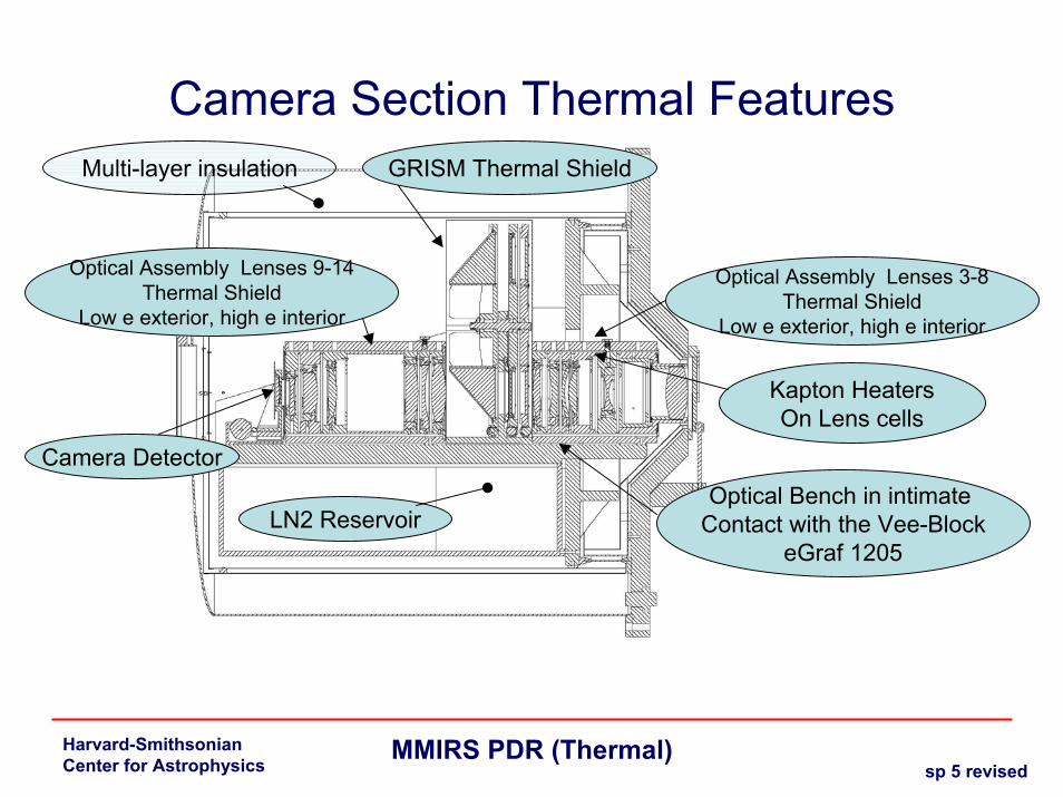
Camera Section Thermal Features
LN2 Reservoir
Optical Assembly Lenses 3-8Thermal Shield
Low e exterior, high e interior
GRISM Thermal ShieldMulti-layer insulation
Optical Assembly Lenses 9-14Thermal Shield
Low e exterior, high e interior
Camera DetectorOptical Bench in intimate
Contact with the Vee-BlockeGraf 1205
Kapton HeatersOn Lens cells
sp 5 revised

Harvard-SmithsonianCenter for Astrophysics
MMIRS PDR (Thermal)
Optical Bench Thermal Design•100w Heater power total
• 2x 50w heater zones• Proportional heater controller
CryoCon Model 34 (Baseline)• MINCO Kapton Heaters
• 12 temperature sensors• 8 sensors from the controller• 4 sensors from data logger
• Rate of cooling: Approximately 72 hours•Maintain less than 2 degree C gradient in lenses
sp 6

Harvard-SmithsonianCenter for Astrophysics
MMIRS PDR (Thermal)
Optical Bench Thermal Design•Thermal Shroud, internal surface finished with black hard anodize
•Emissivity=0.9 •Thermal radiation dominant design
•Thermal Shroud, external surface finished with Low “e” tape (Aluminized Kapton, low outgas)
•Emissivity= range 0.03 - 0.05
•Multi-layer Insulation (effective emissivity = 0.02 – 0.03) to cover internal surface of the most outer housing structure
•Intimate contact with the LN2 reservoir• GrafTech eGraf 1205 thermal interface material
sp 7

Harvard-SmithsonianCenter for Astrophysics
MMIRS PDR (Thermal)
Optical Bench Thermal Design
• Camera section Dewar has 100+ liters of LN2 capacity– Integrated vertical internal fins
• Thermal path• Liquid baffles
– Hold time: approximately 48 hours• Boil-off rate: .022 liter/hr-watt• Approximately 100w absorbed from the local ambient at 20C• Based on effective emmitance of 0.03 (multi-layer insulation)
– Continuous supply of LN2 during the cool down period
sp 8

Harvard-SmithsonianCenter for Astrophysics
MMIRS PDR (Thermal)
Optical AssemblyThermal Math Model :
Thermal Desktop/SINDA (Finite Difference Analyzer)
sp 9

Harvard-SmithsonianCenter for Astrophysics
MMIRS PDR (Thermal)
Optical AssemblyResults Thermal Math Model
Worst case: 100% radiation heat transfer Shown
Requires Conductive path,Design to be determined
sp 10

Harvard-SmithsonianCenter for Astrophysics
MMIRS PDR (Thermal)
Thermal PropertiesDescription Material Thermal Conductivity Specific Heat Density
K at Temperature (k) Cp at Temperature (k) J/kg-k
Lens 3,4,8 CaF2 10 w/m-k 273k 0.204 cal/g-k 3.18 gm/cc9.71 w/m-k 888 J/Kg-k 3.18 gm/cc9.71 w/m-k 854 J/Kg-k 3.18 gm/cc
88 61 85.32 280 3.18 gm/cc200 16.5 104.51 577320 11.7 186 699
216.4 757276 837
296.5 853
Lens 5 BaF2 286 11.72 w/m-k 410 J/Kg-k 4.89 gm/cc286 11.7 w/m-k 274 .096 cal/gm-k311 7.1 w/m-k 0.456e3 J/Kg-C 4.89 gm/cc at 20C
Lens 6 ZnSe 298 18 w/m-k 339 J/Kg-k 5.27 gm/cc300 18 w/m-k 296 0.081 cal/gm-k 5.27 gm/cc
Lens 7 Fused Qtz 2 w/m-k 2.21e3 kg/m-3283 1.46 w/m-k 298 670-740 J/kg-k 2.2 gm/cc
J/kg-k23 0.56 73 218.18
148 1.12 193 400273 1.44 393 800344 1.6
sp 11

Harvard-SmithsonianCenter for Astrophysics
MMIRS PDR (Thermal)
Thermal Properties
GrafTech eGraf 1205 as a thermal interface material between the Optical assembly/Optical bench and MOS Dewar/the wheel support plate
sp 12

Harvard-SmithsonianCenter for Astrophysics
MMIRS PDR (Thermal)
Optics Thermal Math Models
Lens #3 CaF2
sp 13

Harvard-SmithsonianCenter for Astrophysics
MMIRS PDR (Thermal)
Optics Thermal Math Models
Lens #3: Cool down Profile to maintain less than 2 deg C gradient
Based on 8 hour shroud temperature transition
Temp (k) vs. time (sec)(259.2ksec = 3 calendar days)
sp 14

Harvard-SmithsonianCenter for Astrophysics
MMIRS PDR (Thermal)
Optics Thermal Math Models
Lens #4 CaF2
sp 15

Harvard-SmithsonianCenter for Astrophysics
MMIRS PDR (Thermal)
Optics Thermal Math Models
Lens #4: Cool down Profile to maintain less than 1.4 deg C gradientBased on 8 hour shroud temperature
transition
Temp (k) vs. time (sec)(259.2ksec = 3 calendar days)
sp 16

Harvard-SmithsonianCenter for Astrophysics
MMIRS PDR (Thermal)
Optics Thermal Math ModelsLens #5 BaF2
sp 16a

Harvard-SmithsonianCenter for Astrophysics
MMIRS PDR (Thermal)
Optics Thermal Math Models
Lens #5: Cool down Profile to maintain less than 4.0 deg C gradientBased on 8 hour shroud temperature
transitionTemp (k) vs. time (sec)(259.2ksec = 3 calendar days)
BaF2 is known to be susceptible to Thermal Shock
sp 16b

Harvard-SmithsonianCenter for Astrophysics
MMIRS PDR (Thermal)
Optics Thermal Math ModelsLens #3 CaF2
Lens Valve Temperature = 20 degC (293k)
Lens #3 Temperature profile
Tf = 86.6K
Lens #3: Lens Valve Temperature Response ProfileAssumption: Initial Temperature=80K
Temp (k) vs. time (sec)(28.8ksec = 8.0 Hours)
sp 16c

Harvard-SmithsonianCenter for Astrophysics
MMIRS PDR (Thermal)
MOS Section
sp 17
Harvard-SmithsonianCenter for Astrophysics
MMIRS PDR (Thermal)
MOS Section• MOS Section has 45+ liters of LN2 capacity
– Integrated internal fins• Thermal path• Liquid baffles
– Hold time: approximately 40 hours at Max capacity• Potentially only 15 liters may be filled based on a fill orientation
– Approximately 13 hours hold-time (horizon pointing, fill-tube at bottom)
• Boil-off rate: 0.022 liter/hr-watt• Approximately 50w absorbed from the local ambient at 20C• Based on effective emittance of 0.03 (Thermal shields plus Multi-
layer insulations)
– Continuous supply of LN2 during the cool down period
sp 18

Harvard-SmithsonianCenter for Astrophysics
MMIRS PDR (Thermal)
MOS Section Thermal Design• Surface finishes
– Internal to thermal shield: Black Anodize finishes
– External to the thermal shield: Low “e” tape (Aluminized Kapton, low outgas)
• Thermal shield locations• Dewar location
• 4 temperature sensors– 4 sensors from data logger
sp 19
Harvard-SmithsonianCenter for Astrophysics
MMIRS PDR (Thermal)
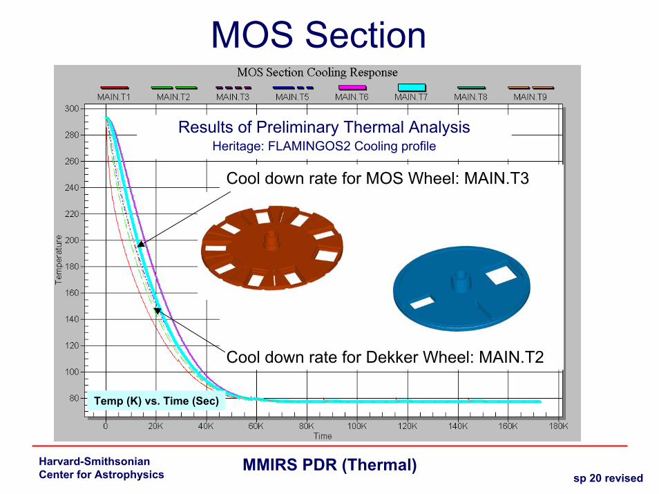
MOS Section
Results of Preliminary Thermal AnalysisHeritage: FLAMINGOS2 Cooling profile
Cool down rate for MOS Wheel: MAIN.T3
Cool down rate for Dekker Wheel: MAIN.T2
Temp (K) vs. Time (Sec)
sp 20 revised

Harvard-SmithsonianCenter for Astrophysics
MMIRS PDR (Thermal)
Planned activities• Camera Section
– Analyze Detector Assembly– Improve transition time to cool down– Generate detailed thermal math model (TMM)
• Analyze individual lens thermal performances• Grism wheel thermal profiles
– Characterize thermal interaction between the camera and MOS sections
• MOS Section– Improve transition time to cool down– Design thermal shield– Determine temperature stability due to the environmental conditions
• Integrated Thermal-Stress Model
• Specify and order thermal related components (heater, MLI materials, surface finishes/tapes etc.)
sp 21


