The Shoreline Stabilization Handbook
for Lake Champlainand Other Inland Lakes

Additional copies of this handbook can beobtained from the:
Northwest Regional Planning Commission
7 Lake Street, Suite 201St. Albans, VT 05478
Tel: (802) 524-5958
Email: [email protected]
This project was funded by the member municipalities of the Northwest Regional Planning Commission,Vermont with grants and contributions from:
NOAA Sea Grant College Program, US Department ofCommerce, under Grant Number NA16RG2206. LakeChamplain Sea Grant is a joint federal and state pro-gram of the University of Vermont and PlattsburghState University. This is Lake Champlain Sea GrantPublication LCSG-04-03.
Lake Champlain Basin Program under the authority ofthe Lake Champlain Special Designation Act of 1990,P.L. 101-596, through the US Environmental ProtectionAgency, grant #LC991923-01.
Federal Emergency Management Agency (FEMA)
Addison County Regional Planning Commission
Vermont Local Roads Program
Vermont Agency of Transportation
Vermont Agency of Commerce and CommunityDevelopment
Champlain Water District
Publication of this report does not signify that the con-tents reflect the views of the project participants orcontributors, including those listed in the publicationand the States of New York and Vermont, the LakeChamplain Basin Program and the US EnvironmentalProtection Agency.
Printed in Vermont with soy based inks on PCF (processchlorine free) 100% post-consumer waste recycled paper
ISBN# 0-9754546-0-9

Acknowledgments
T his handbook is for area residents and gov-ernment officials who are working to create
and maintain a landscape that complements LakeChamplain’s setting and ecology, while enhancingopportunities for the enjoyment of its natural andrecreational features.
While some of the introductory information isspecific to Lake Champlain, many of the erosioncontrol and stabilization techniques are applicableto smaller lakes as well.
The idea for this project began after the icestorm of January 1998, which resulted in animmediate and significant loss of trees in theChamplain Valley. The temporary loss of vegetationhas accelerated existing shoreline destabilizationand created new areas of destabilization.Discussions with representatives from state and
federal agencies, local municipalities, and regionalorganizations around the lake identified the needfor a comprehensive approach to shoreline stabi-lization that considered a range of environmentallysensitive options tailored to site conditions, costs,and effectiveness.
Much of the information used for this handbookis not new. Section 2 was adapted from theposter, “Protect Your Shore,” published by the NewEngland River Basin Commission in the mid-1970’s as part of the Lake Champlain Basinstudy. The Shoreline Stabilization Handbook builtupon this poster’s basic content and incorporatedinformation on stabilization that has been devel-oped during the past 30 years. Section 6 providesreferences for the resources used.
The Northwest Regional Planning Commissioncoordinated and staffed the project. The Town ofHighgate, Vermont provided support for the hand-book’s development. Griffin International, Inc. ofWilliston, Vermont, Kehoe +Kehoe DesignAssociates of Burlington, Vermont, and FullerCommunications of Malone, New York providedpublication assistance.
The Northwest Regional Planning Commissionextends its sincerest appreciation to the local,regional, state, and federal partners from Vermontand New York who provided information and com-ments for the development of this handbook.Without their insight, this handbook would nothave been published.
Jurij Homziak UNIVERSITY OF VERMONT,
LAKE CHAMPLAIN SEA GRANT
Susan Warren VT DEPARTMENT OF ENVIRONMENTAL
CONSERVATION, WATER QUALITY DIVISION
Bonnie Waninger NORTHWEST REGIONAL
PLANNING COMMISSION
Larry Becker VERMONT GEOLOGICAL SURVEY
Tim Bouton ADDISON COUNTY, VT REGIONAL PLANNING
COMMISSION
Colleen Hickey LAKE CHAMPLAIN BASIN PROGRAM
George Clifford and David WitkowskiCUMBERLAND HEAD TOMORROW
David Hoyt USDA NATURAL RESOURCES CONSERVATION SERVICE
Janet Hurley TOWN OF MILTON AND CITY OF SOUTH
BURLINGTON, VT
Sarah Hadd TOWN OF COLCHESTER, VT
Steve Mahoney CLINTON COUNTY, NY SOIL & WATER
CONSERVATION DISTRICT
Larry Kempton TOWN OF HIGHGATE, VT
Karen Bates VT DEPARTMENT OF ENVIRONMENTAL
CONSERVATION
Gil Newbury VT AGENCY OF TRANSPORTATION, DISTRICT 8
Wilfred (Pete) LaPete LAPETE CONSTRUCTION
Bob Collins OTTER CREEK CONSERVATION DISTRICT
Ken Kogut NYS DEPARTMENT OF ENVIRONMENTAL
CONSERVATION
Art Stemp NYS DEPARTMENT OF ENVIRONMENTAL
CONSERVATION
Hank Lambert VERMONT LOCAL ROADS PROGRAM
David Raphael LANDWORKS, AND TOWN OF PANTON, VT
PLANNING COMMISSION
Lani Ravin VT AGENCY OF TRANSPORTATION POLICY AND
PLANNING DIVISION
Wally and Betty Shonnard LAKE CHAMPLAIN
RESTORATION ASSOCIATION
Joseph and Nancy Ballister LAKE CHAMPLAIN
RESTORATION ASSOCIATION
Michael Barsotti CHAMPLAIN WATER DISTRICT
T H E S H O R E L I N E S T A B I L I Z A T I O N H A N D B O O K Acknowledgments
Introduction
S horeline erosion around bodies of water is a naturalprocess that brings both benefits and damages.
Some of the benefits include the creation and resupplyof natural beaches, and the creation of habitat for fishand wildlife. When erosion is severe or too close tostructures, it can result in property loss, structural dam-age to roadways and/or houses, and poor water quality.Sometimes erosion becomes a problem when roads orstructures are built unknowingly in erosion prone areas.Learning to recognize where erosion may interfere withstructures or infrastructure can help you avoid this problem. Shoreline erosion can be modified by humanactivity.
This handbook is a result of a growing interest tomanage the process of shoreline erosion to preventloss of property and structures in the Lake ChamplainBasin. It is intended for use by landowners and theirconsultants, municipalities, and state and local authori-ties. You will find information regarding the character-istics of Lake Champlain and the potential causes oferosion. The handbook provides specific shoreline stabi-lization options, including hard structural methods andbioengineered methods. Guidance is provided on how toplan stabilization activities and obtain required permits.You will also find a list of additional resources and aglossary of terms used in the handbook.
Traditional shoreline protection methods, such as seawalls and embankments of large stones, can be very effective; however, many such methods are expensive and can have detrimental, unintended envi-ronmental consequences. In the Lake Champlain Basin,there has been a significant effort to find natural,cost effective processes, such as bioengineering, thatuse live plantings, as well as other methods such asland-use planning, to modify the processes of shorelineerosion.
Introduction T H E S H O R E L I N E S T A B I L I Z A T I O N H A N D B O O K

T H E S H O R E L I N E S T A B I L I Z A T I O N H A N D B O O K Contents 1
Section 5 / page 37
Permits
• when you need a permit
• what is the permit process
• what levels of government have jurisdiction
Section 6 / page 39
Resources
• additional reading and information sourcesabout shoreline erosion controls
• contact information for government agenciesand offices
Section 7 / page 44
Glossary of TermsUsed in the Handbook
• explanations and definitions of words andtechniques used in the handbook
Section 8 / page 46
Index
Section 1 / page 2
The Characteristics of Lake Champlain
• a description of the lake, its majorcharacteristics and surrounding geography
• a map of the Lake Champlain Basin
Section 2 / page 4
The Causes of Erosion
• the specific forces that cause shoreline erosion
• descriptions of the types of erosion that result
Section 3 / page 8
Planning Your Erosion Control Installation
• what needs to be taken into account
• who should be involved
• when is the best time of year to do the work
Section 4 / page 12
An Introduction to Erosion Controls
• a comparison of stabilization techniques
• the pros and cons of available options
• descriptions of how to build various erosioncontrol installations
• guidelines for success
• how to monitor the results
Contents

Section 1 / General Characteristics2 T H E S H O R E L I N E S T A B I L I Z A T I O N H A N D B O O K
General Characteristics
Lake Champlain is about 120 miles long andis oriented almost due north-south. The
shoreline touches New York State, Vermont, andQuebec, Canada. The lake flows north into theRichelieu River and is joined to the Hudson Riverdrainage by the Champlain Canal. There are 570miles of shoreline, and the Lake Champlain Basinencompasses 8,234 square miles.
The lake is bounded by the AdirondackMountains to the west and the Green Mountainsto the east. The mountains dictate prevailing westerly winds and create strong northerly andsoutherly winds as well. Due to the mountains andoccasional strong storms with heavy winds, themean annual wind speed over the lake varies sig-nificantly. Wind speeds as high as 72 mph havebeen recorded in the Lake Champlain Basin.
The lake’s water level fluctuates due to precipi-tation, evaporation, runoff, and groundwater yield.The mean water level of Lake Champlain is 95.5feet. The record high water level in the lake was101.89 at Rouses Point in 1993, and the recordlow water level was 92.4 in 1908. The averageannual water level peak usually occurs in April orMay after snow and ice have melted. The annuallow usually occurs in October or November.
The Lake Champlain Basin generally receives asignificant amount of annual rainfall, ranging fromabout 30 inches on the northwest shore to 60inches in the mountains.
Economic development and population growthare increasing in the Basin. Residential and com-mercial developments on the shores of the lakehave the potential to increase the natural rate oferosion and damage the long-term integrity of thelake’s shoreline.
Lake Champlain Basin
Topographic map courtesy of the
Lake Champlain Basin Program

T H E S H O R E L I N E S T A B I L I Z A T I O N H A N D B O O K Section 1 / General Characteristics 3
Causes of erosion can be grouped into the following categories:
• terrestrial forces • aquatic forces • human activities
Terrestrial and aquatic forces generally worktogether, and each can cause specific types ofshoreline erosion.
Section 2 / Causes of Erosion4 T H E S H O R E L I N E S T A B I L I Z A T I O N H A N D B O O K
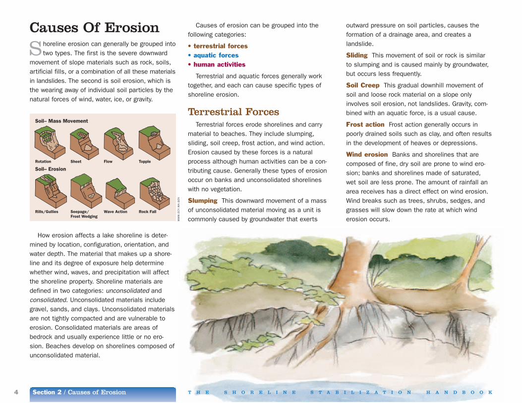
Causes Of Erosion
S horeline erosion can generally be grouped intotwo types. The first is the severe downward
movement of slope materials such as rock, soils,artificial fills, or a combination of all these materialsin landslides. The second is soil erosion, which isthe wearing away of individual soil particles by thenatural forces of wind, water, ice, or gravity.
Soil– Mass Movement
Soil– Erosion
Rotation Sheet Flow Topple
Rills/Gullies Seepage/Frost Wedging
Wave Action Rock Fall
How erosion affects a lake shoreline is deter-mined by location, configuration, orientation, andwater depth. The material that makes up a shore-line and its degree of exposure help determinewhether wind, waves, and precipitation will affectthe shoreline property. Shoreline materials aredefined in two categories: unconsolidated and consolidated. Unconsolidated materials includegravel, sands, and clays. Unconsolidated materialsare not tightly compacted and are vulnerable toerosion. Consolidated materials are areas ofbedrock and usually experience little or no ero-sion. Beaches develop on shorelines composed ofunconsolidated material.
Terrestrial ForcesTerrestrial forces erode shorelines and carry
material to beaches. They include slumping,sliding, soil creep, frost action, and wind action.Erosion caused by these forces is a naturalprocess although human activities can be a con-tributing cause. Generally these types of erosionoccur on banks and unconsolidated shorelineswith no vegetation.
Slumping This downward movement of a mass of unconsolidated material moving as a unit iscommonly caused by groundwater that exerts
outward pressure on soil particles, causes the formation of a drainage area, and creates a landslide.
Sliding This movement of soil or rock is similarto slumping and is caused mainly by groundwater,but occurs less frequently.
Soil Creep This gradual downhill movement ofsoil and loose rock material on a slope onlyinvolves soil erosion, not landslides. Gravity, com-bined with an aquatic force, is a usual cause.
Frost action Frost action generally occurs inpoorly drained soils such as clay, and often resultsin the development of heaves or depressions.
Wind erosion Banks and shorelines that arecomposed of fine, dry soil are prone to wind ero-sion; banks and shorelines made of saturated,wet soil are less prone. The amount of rainfall anarea receives has a direct effect on wind erosion.Wind breaks such as trees, shrubs, sedges, andgrasses will slow down the rate at which wind erosion occurs.W
WW
.EC
Y.W
A.G
OV

T H E S H O R E L I N E S T A B I L I Z A T I O N H A N D B O O K Section 2 / Causes of Erosion 5
Aquatic ForcesAquatic forces include raindrop splash, sheet
erosion, rilling, gullying, wave action, longshoredrift, and ice push. Aquatic forces remove materialfrom the beach as well as the bank during highlake levels and often remove material from onearea and deposit it elsewhere.
Raindrop splash Soil erosion occurs when rain-drops hit directly on exposed soil. In heavy stormsa significant amount of soil can be splashed up inthe air. This occurs on both level and steep banksbut has more severe results on steeper slopes.
Sheet erosion Storm water flow that occurs insheets removes thin layers of soil from slopingland. Sheet erosion tends to be less severe thanraindrop splash. The extent of erosion resultingfrom sheet flow is dependent on depth and veloc-ity of runoff and the given size and shape of aslope.
Rilling Soil is removed in very small but well-defined channels or streamlets where there is aconcentration of overland water flow. Rilling is themost common process of rainfall erosion losses.Rilling is most severe at sites that have a combi-nation of steep slopes and loose unconsolidatedmaterials.
Gullying This is the removal of soil by intermit-tent larger diameter stream channels. The totalamount of soil eroded due to gullies is not necessarily as great as that removed from rilling.However, gullies are more difficult to fix and prevent.
Wave action This is the impact of waves hittingdirectly on exposed soil. Lake Champlain wavesvary with wind speeds and duration, water depth,and the continuous length of water over which
winds blow in one direction. Wave heights can becalculated when these properties are known.Choosing and designing a shoreline stabilizationmethod requires knowing the maximum height ofwaves affecting the property. Each shoreline alongthe lake is different. Waves on Lake Champlaincan also be created by heavy boat traffic nearshorelines.
The extent of soil erosion from wave actiondepends greatly on the bank slope, vegetation,and bank composition. Natural beaches serve as
Paved roadways built along the shores of a lakeincrease the velocity of stormwater runoff that accelerates bank erosion.
Natural Shoreline Processes
The Lake Champlain shoreline is notstatic. Wave and wind action, changingwater levels, currents, and sediments car-ried in by rivers all work together to exertconstant pressure on the lakeshore. Theseforces both erode and build the shoreline.It is important to consider the naturalforces along a particular stretch of shore-line in order to avoid interfering with abeneficial natural process.
One such process is longshore drift.When waves come at the shore at even a slight angle, sediment is moved alongthe shore. This sediment results in the creation and maintenance of beaches onthe shore. Stabilizing such a critical bankwould likely result in erosion of that beachor other stretches of shoreline if its sedi-ment supply is cut off.
➡ ➡ ➡ Longshore current direction ➡ ➡ ➡
Beach
Incoming waves
➡
➡
Sediment Movement
GR
IFFI
NIN
TER
NA
TIO
NA
L, I
NC
.
Urbanization Beaches that are modified for per-sonal use or land that is cleared for housing orroadways increase the opportunity for soil erosion.Urbanization has lead to a huge loss of naturalvegetation along the Lake Champlain shorelineincreasing the rate of erosion. Development ofhousing uphill of a bank can result in increasedstormwater runoff over the bank.
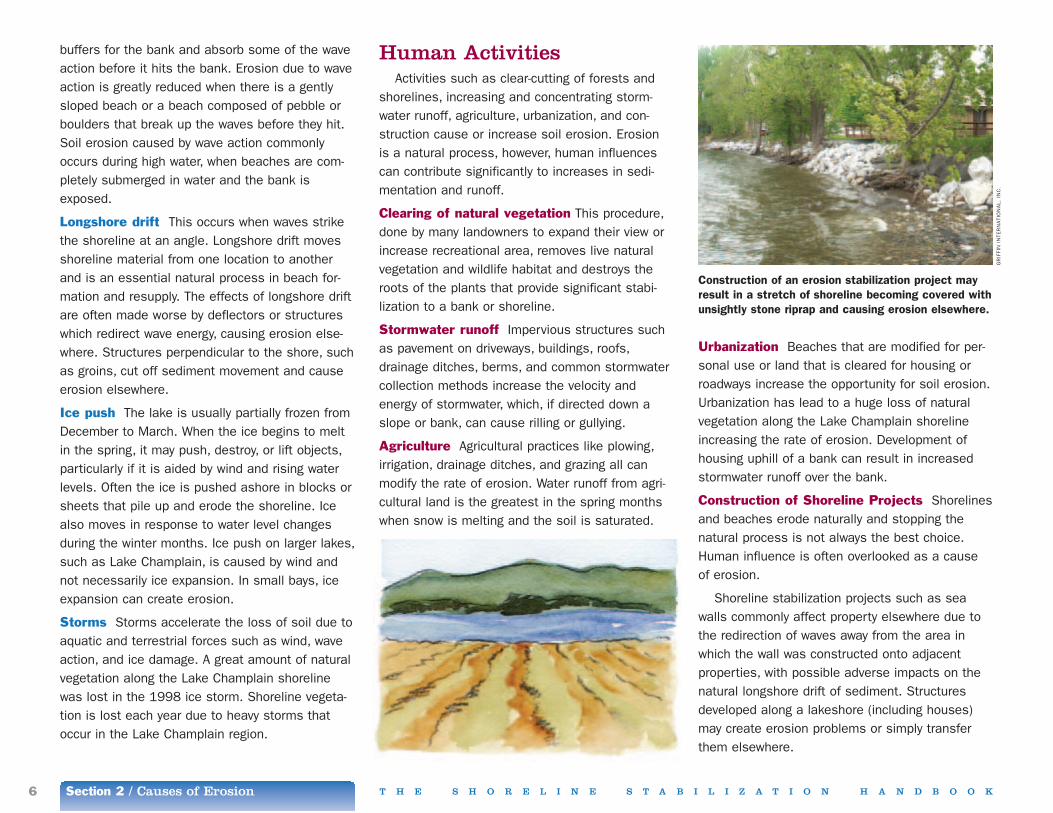
Construction of Shoreline Projects Shorelinesand beaches erode naturally and stopping the natural process is not always the best choice.Human influence is often overlooked as a cause of erosion.
Shoreline stabilization projects such as seawalls commonly affect property elsewhere due tothe redirection of waves away from the area inwhich the wall was constructed onto adjacentproperties, with possible adverse impacts on thenatural longshore drift of sediment. Structuresdeveloped along a lakeshore (including houses)may create erosion problems or simply transferthem elsewhere.
Section 2 / Causes of Erosion6 T H E S H O R E L I N E S T A B I L I Z A T I O N H A N D B O O K
buffers for the bank and absorb some of the waveaction before it hits the bank. Erosion due to waveaction is greatly reduced when there is a gentlysloped beach or a beach composed of pebble orboulders that break up the waves before they hit.Soil erosion caused by wave action commonlyoccurs during high water, when beaches are com-pletely submerged in water and the bank isexposed.
Longshore drift This occurs when waves strikethe shoreline at an angle. Longshore drift movesshoreline material from one location to anotherand is an essential natural process in beach for-mation and resupply. The effects of longshore driftare often made worse by deflectors or structureswhich redirect wave energy, causing erosion else-where. Structures perpendicular to the shore, suchas groins, cut off sediment movement and causeerosion elsewhere.
Ice push The lake is usually partially frozen fromDecember to March. When the ice begins to meltin the spring, it may push, destroy, or lift objects,particularly if it is aided by wind and rising waterlevels. Often the ice is pushed ashore in blocks orsheets that pile up and erode the shoreline. Icealso moves in response to water level changesduring the winter months. Ice push on larger lakes,such as Lake Champlain, is caused by wind andnot necessarily ice expansion. In small bays, iceexpansion can create erosion.
Storms Storms accelerate the loss of soil due toaquatic and terrestrial forces such as wind, waveaction, and ice damage. A great amount of naturalvegetation along the Lake Champlain shorelinewas lost in the 1998 ice storm. Shoreline vegeta-tion is lost each year due to heavy storms thatoccur in the Lake Champlain region.
Human ActivitiesActivities such as clear-cutting of forests and
shorelines, increasing and concentrating storm-water runoff, agriculture, urbanization, and con-struction cause or increase soil erosion. Erosion is a natural process, however, human influencescan contribute significantly to increases in sedi-mentation and runoff.
Clearing of natural vegetation This procedure,done by many landowners to expand their view orincrease recreational area, removes live naturalvegetation and wildlife habitat and destroys theroots of the plants that provide significant stabi-lization to a bank or shoreline.
Stormwater runoff Impervious structures suchas pavement on driveways, buildings, roofs,drainage ditches, berms, and common stormwatercollection methods increase the velocity andenergy of stormwater, which, if directed down aslope or bank, can cause rilling or gullying.
Agriculture Agricultural practices like plowing,irrigation, drainage ditches, and grazing all canmodify the rate of erosion. Water runoff from agri-cultural land is the greatest in the spring monthswhen snow is melting and the soil is saturated.
Construction of an erosion stabilization project mayresult in a stretch of shoreline becoming covered withunsightly stone riprap and causing erosion elsewhere.
GR
IFFI
NIN
TER
NA
TIO
NA
L, I
NC
.

T H E S H O R E L I N E S T A B I L I Z A T I O N H A N D B O O K Section 2 / Causes of Erosion 7
Planning YourErosion ControlInstallation
T he siting and installation of the erosion con-trol method to be used is much easier when
you develop a thorough plan that includes thedetails of what needs to be done, materials, andhow, when, and by whom the installation will bedone. This section provides a general guide to creating your plan.
Identify Your Surroundings (Site Evaluation)
A site evaluation is the essential first step todetermine what, if any, shoreline stabilizationmethod is most appropriate. Conferring with yourneighbors can be helpful. Ideally, an entire sectionof shoreline should be evaluated for erosioncauses and natural processes before a stabiliza-tion plan is developed.
Determining the slope angle and height of theshoreline bank, the type of soil present, drainagecharacteristics, the type of vegetation growing, andthe extent of shoreline erosion are key elementsof the site evaluation. The information developedduring the evaluation will help you determine themost appropriate erosion control solution.
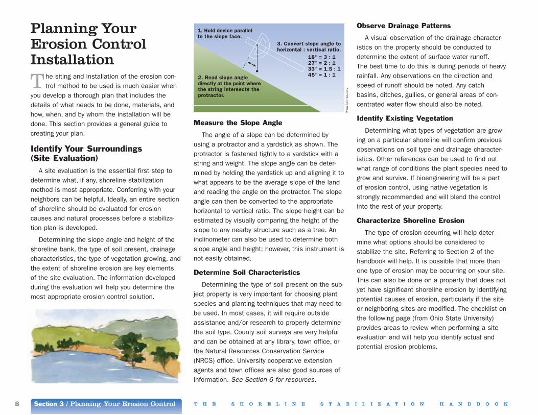
Measure the Slope Angle
The angle of a slope can be determined byusing a protractor and a yardstick as shown. Theprotractor is fastened tightly to a yardstick with astring and weight. The slope angle can be deter-mined by holding the yardstick up and aligning it towhat appears to be the average slope of the landand reading the angle on the protractor. The slopeangle can then be converted to the appropriatehorizontal to vertical ratio. The slope height can beestimated by visually comparing the height of theslope to any nearby structure such as a tree. Aninclinometer can also be used to determine bothslope angle and height; however, this instrument isnot easily obtained.
Determine Soil Characteristics
Determining the type of soil present on the sub-ject property is very important for choosing plantspecies and planting techniques that may need tobe used. In most cases, it will require outsideassistance and/or research to properly determinethe soil type. County soil surveys are very helpfuland can be obtained at any library, town office, orthe Natural Resources Conservation Service(NRCS) office. University cooperative extensionagents and town offices are also good sources ofinformation. See Section 6 for resources.
Observe Drainage Patterns
A visual observation of the drainage character-istics on the property should be conducted todetermine the extent of surface water runoff. The best time to do this is during periods of heavyrainfall. Any observations on the direction andspeed of runoff should be noted. Any catchbasins, ditches, gullies, or general areas of con-centrated water flow should also be noted.
Identify Existing Vegetation
Determining what types of vegetation are grow-ing on a particular shoreline will confirm previousobservations on soil type and drainage character-istics. Other references can be used to find outwhat range of conditions the plant species need togrow and survive. If bioengineering will be a partof erosion control, using native vegetation isstrongly recommended and will blend the controlinto the rest of your property.
Characterize Shoreline Erosion
The type of erosion occurring will help deter-mine what options should be considered tostabilize the site. Referring to Section 2 of thehandbook will help. It is possible that more thanone type of erosion may be occurring on your site.This can also be done on a property that does notyet have significant shoreline erosion by identifyingpotential causes of erosion, particularly if the siteor neighboring sites are modified. The checklist onthe following page (from Ohio State University) provides areas to review when performing a siteevaluation and will help you identify actual andpotential erosion problems.
2. Read slope angledirectly at the point wherethe string intersects theprotractor.
1. Hold device parallelto the slope face.
3. Convert slope angle tohorizontal : vertical ratio. 18° = 3 : 1 27° = 2 : 1 33° = 1.5 : 1 45° = 1 : 1
Section 3 / Planning Your Erosion Control8 T H E S H O R E L I N E S T A B I L I Z A T I O N H A N D B O O K
WW
W.E
CY
.WA
.GO
V

Shoreline Checklist1. On what shore type is your property located?
■■ high erodible bluff (greater than 30 feet high)■■ low erodible bluff (10 to 30 feet high)■■ low erodible plain (less than 10 feet high)■■ sand dunes■■ wetlands or marsh
2. Describe your shoreline property. (Measure thedistance with a tape and answer below)
How high above the water level is your house?
__________________________________________________________________________
How close to the edge of a bluff is your house?
__________________________________________________________________________
How close are the other structures to the edge ofa bluff?
__________________________________________________________________________
What is the angle of slope of the bluff, sand duneor beach? (see previous page on how todetermine)
__________________________________________________________________________
How wide is the beach from the waterline to thebase of the bluff?
__________________________________________________________________________
3. What kind of materials make up the bluff?
■■ sand■■ one layer of clay or unstratified material■■ one layer of sand or silt■■ bedrock■■ mixed layers of sand, silt, clay or till
4. What kind of materials make up the beach?
■■ sand■■ sand and gravel■■ gravel and rock■■ other (specify) _________________________________________________
5. What are the problems along your shoreline?(Check all appropriate answers)
Wave action
Y ■■ N ■■ Are waves eroding the beach?
Y ■■ N ■■ Are waves eroding the base of the bluffduring storms?
Y ■■ N ■■ Are there presently any shore protectionstructures on your property?
Y ■■ N ■■ Are there presently any shore protectionstructures on your neighbor’s property?
Y ■■ N ■■ Are shore protection structures, ifpresent, in good repair
Groundwater
Y ■■ N ■■ Does groundwater flow out of the faceof your bluff?
Y ■■ N ■■ Is active slumping (landslides)occurring?
In what ways do you add water to the groundwatersupply on the top of the bluff?
■■ septic tank ■■ sprinkler or irrigation■■ drain pipes■■ swimming pool
Surface runoff and wind erosion
Y ■■ N ■■ Are the effects of the following visibleon your property?
■■ raindrop impact ■■ rill (small ruts)■■ gullies
Y ■■ N ■■ Are you contributing to surface runoff?
■■ drain pipes from home or garage■■ sprinkler or irrigation■■ other (specify) _________________________________________________
Y ■■ N ■■ Is sand being blown off the beach orare dunes shifting?
Y ■■ N ■■ Is there any vegetation on the bluff top,face or toe?
Y ■■ N ■■ Was there ever any vegetation on thebluff top, face or toe? (in your memory)
If yes, what happened to it?
__________________________________________________________________________
What vegetation types are (or were) found on thebluff top, face or toe?
■■ trees or woods■■ shrubs or brush■■ grass
Property Use
How do you use your shoreline property?(Check the appropriate answer)
■■ homesite■■ vacation cottage or recreation■■ agriculture or forestry■■ developed for business■■ rental property
How do you use the bluff or backshore area?
■■ for access to beach by foot or vehicle■■ as a place to view the lake■■ as a building site■■ for fill■■ other (specify) ________________________________________________
T H E S H O R E L I N E S T A B I L I Z A T I O N H A N D B O O K Section 3 / Planning Your Erosion Control 9
WW
W.S
G.O
HIO
-STA
TE.E
DU

Section 3 / Planning Your Erosion Control10 T H E S H O R E L I N E S T A B I L I Z A T I O N H A N D B O O K
Draft Your PlanThe next step is to choose a solution for each
of the problems identified.
It is important to identify property surroundingsbefore implementing any process of shoreline stabilization. Areas and structures that should beidentified and considered in the plan-preparationprocess are:
• Wetlands • Natural beaches • Houses • Septic structures • Existing stabilization structures • Neighboring properties • Roadways • Other transportation structures
Who Should be Involved?
The next step in the plan-preparation process isdetermining who is going to be involved. At thispoint, it may be necessary to work with neighborsif similar problems have been observed on theirproperty. Shoreline characteristics and erosionproblems are not limited by property boundaries.
It is helpful to contact state agencies, town andcounty governments or regulatory agencies, countyextension services, or experienced soil engineersbefore proceeding. A list of resources and refer-ences can be found in Section 6. These resourcescan help determine if the erosion identified is anindividual property issue or has broader ramifica-tions. They will also help you decide what shorelinestabilization method, if any, may be best for thesubject property and how to proceed in implement-ing the chosen method.
It is recommended that, when possible, anymethod of shoreline stabilization involve neighborsfrom the very beginning of the plan-preparationprocess. Trying to solve a shoreline erosion prob-lem without talking to your neighbors can result infailure. It can also worsen impacts to neighboringproperties. If similar problems are occurring onadjacent properties, teaming up with the neighborsmay well make the erosion control installationmore effective. Designing a shoreline protectionmethod that covers a greater distance may resultin less cost per linear foot and minimize inadver-tent impacts to adjacent shorelines. The permitprocesses used both in Vermont and New YorkState call for a period of public consultation andreview of proposed activities. Before you begin thepermit process, it is good practice and commonsense to advise your neighbors of your plan. Atthis point, you should answer questions, addressobjections, and obtain their support. This interac-tion can help you minimize unanticipated costsand may streamline the permit process.
Choosing The Best Method For You
The information gathered from your site evalua-tion and from any outside professionals should bebrought together to determine what, if any, method
of shoreline stabilization is needed. The matrixpresented in Section 4 will help in the decisionprocess. You should keep in mind all of theoptions, including doing nothing, before making afinal decision.
If your decision results in an erosion controlinstallation, you should make every effort to incor-porate preservation of natural vegetation anddrainage and the establishment of shoreline bufferzones in planning your control design. Using acomprehensive approach to site planning anddevelopment will identify features and conditionsas well as opportunities to reduce the need forstructural controls. The use of natural vegetationshould always be considered before implementingany structural techniques.
The local site development and plan reviewprocess is often the mechanism where site selec-tion and site design are closely evaluated forcompliance with the criteria used by your localcommunity and state for land use planning andenvironmental management.
Preparation
Before any land preparation can be performed,the state and/or federal permitting process mustbe completed. Section 5 of the handbook coverspermit requirements and the permitting processesused by the various levels of government andagencies involved.
Land Preparation
Grading and shaping a bank does not alwaysneed to be performed and should be avoided ifpossible. Many banks are naturally graded to theapproximate angle and shape needed for a shore-line stabilization structure to be installed.

Preparing a property begins with grading andshaping the slope if it is needed. When gradingand shaping the slope, it is important to try toavoid introducing water into or onto the slopebecause this will likely increase the extent of ero-sion during construction, and change the slopecharacteristics.
If the option is available, all existing vegetationshould be maintained. If vegetation needs to beremoved, the local zoning and planning administra-tor should be informed. In Vermont, there aresome towns with ordinances regarding clear cut-ting vegetation. The ordinance requirements needto be addressed before doing any cutting.
The following three areas should be equally prepared when grading and shaping a slope: the slope crest (the area along the edge of thetop of the slope), the slope face (the flat surfaceon the slope), and the slope toe (the bottom ofthe slope face where it flattens out).
These guidelines are recommended when grad-ing and shaping a slope:
• Grade the slope face back to a stable angle andshape
• Protect the toe of the slope against scour andundermining using rocks or boulders
• Protect the slope face against raindrop splashand frost action with erosion matting
• Divert or intercept upland water flow away fromthe slope crest
• Intercept or prevent seepage from forming at theslope crest
• Any revegetation should be performed above thetoe of the bank
• Use erosion control prevention matting
Grading the slope to a stable angle generally
T H E S H O R E L I N E S T A B I L I Z A T I O N H A N D B O O K Section 3 / Planning Your Erosion Control 11
Property InsuranceIn most cases, homeowner’s property
insurance policies do not cover erosiondamage. If your property is in a floodplainit may be eligible for federal governmentfunding through the National Flood Insur-ance Program from the Federal EmergencyManagement Agency (FEMA). However,this insurance only covers damage tobuildings. It does not usually cover con-struction of, or damage to erosion controlmethods.
You can determine if your property islocated in a floodplain by looking at floodinsurance maps. If structures on your prop-erty are located at or below the 100-yearflood line, your lending agency will likelyrequire you to purchase flood insurance.The 100-year flood line on Lake Champlainis approximately 102 feet above sea level.The National Flood Insurance Program onlycovers floods due to high water levels. Itis recommended that everyone who ownsor is considering the purchase of lakeshoreproperty determine what insurance is avail-able for that property.
Sources for additional information onflood insurance can be acquired throughlocal insurance agents, municipalities, and flood insurance maps. Flood insurancemaps for Vermont and New York can beviewed at regional planning commissionsand town and city offices. Section 6includes more information regarding floodinsurance.
means an inclination of no more than 1.5 feet horizontal to 1 foot vertical; however, the anglecan be increased depending on the soil type and ifbioengineering methods are incorporated into theplan. The appropriate slope angle for each methodis mentioned in Section 4 of the handbook. Aslope of 2:1 or less is adequate for plant develop-ment and growth; however, anything greater thanthis may not be suitable for plant development.
Slopes may need to be cut or filled to achievethe desired grade and shape. Cut slopes shouldbe rounded at the top and sides to blend with thesurroundings, and provide an environment suitablefor plant development. Creating terraces on cutslopes will slow upland water runoff and provide abase for seeds and plants. Boulders, stumps,and/or large debris may need to be removed atthe top of a slope and overhangs. Loose rocksshould be removed, working from top to bottom ofthe slope. Material removed may be used for theconstruction of a wall or for backfill.
The slope should be smoothed out to removeany gullies or rills. This may require using backfill.Caution should be used when applying fill becauseit sometimes creates compaction of the soil.
Funding of Construction Costs
For many public erosion control projects, andsome private ones, government funding assistancewith construction costs may be available. It ishelpful to check with federal and state agenciesand regional organizations about grants and loansrelated to water quality protection, hazard or disas-ter mitigation, transportation infrastructure, andnatural resource protection. Section 6 includescontact information for agencies and organizationsthat may offer financial or technical assistance forconstruction activities.
Section 4 / Erosion Control Methods12 T H E S H O R E L I N E S T A B I L I Z A T I O N H A N D B O O K

T H E S H O R E L I N E S T A B I L I Z A T I O N H A N D B O O K Section 4 / Erosion Control Methods 13
An Introduction to Erosion ControlMethods
T oday we know more about the potentialimpacts of development on environmental
and water resources. We have learned that impactassessments of proposed shoreline erosion con-trol installations should consider the combinedeffects that the project may have on a commonshoreline, as well as the cause(s) of the erosion.This approach identifies and avoids incrementaldegradation of a shoreline when short-term solu-tions are used or when solutions on one propertyimpact neighboring shorelines by displacing theerosion.
Choosing what erosion control method will workbest for a particular segment of shoreline is themost difficult step in implementing a stabilizationprocess. It requires an understanding of thecauses of erosion and physical characteristics ofthe shoreline and adjacent land. Erosion is some-times a problem because previous structures weresited inappropriately, without taking into considera-tion erosion processes. In order to successfullyimplement a stabilization method that will workeffectively, while creating minimal impacts to adja-cent properties and the environment, it is impor-tant to consider all available options.
These are methods used for providing shorelineerosion control in the Lake Champlain region:
1. non-structural and preventative2. structural3. bioengineering 4. biotechnical
Non-structural erosion stabilization optionsare often the simplest solution and generally workbest where erosion is minor and where the land ismostly undisturbed by human activity. They mayprovide the best long-term benefit, as well as pro-tecting natural habitat values.
Structural installations have traditionally beenthe first choice to provide shoreline protection, duein part to the greater familiarity of contractors andconsultants with these methods. Hard physicalstructures to secure a shoreline are widely usedand promoted throughout the United States. Theyhave proven to be effective, but tend to be expen-sive, need replacement over time, and can havedetrimental environmental impacts if not properlydesigned and installed.
Bioengineering uses vegetation plantings forshoreline stabilization. Vegetation provides resist-ance against light to moderate wave action. Theplant roots break up the energy of the waves andhold the soil intact while acting as barriers to ero-sion and mass movement, and assisting in waterdrainage. The presence of plants on the shorealso has multiple scenic and fish and wildlife habi-tat advantages.
Biotechnical methods of shoreline stabilizationcombine structural and bioengineering methods tostabilize shorelines. The structural and plant mate-rials work together to provide an improved erosioncontrol in areas of high wave energy or severe ero-sion, minimizing environmental impacts andproviding stability within the system. A biotechnicalapproach is suitable for a wide range of erosionconditions and commonly used to prevent surfaceerosion and shallow mass-movement of soil.
All the methods presented help control or slowdown a natural, ongoing occurrence; they do notprevent erosion.
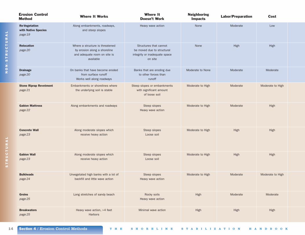
Comparison of Stabilization Techniques
When choosing to apply any shoreline stabiliza-tion method, there is the chance of failure and of causing neighboring impacts. The charts on the following pages are provided to show a com-parison of methods and the advantages anddisadvantages for each. More in-depth informationon each method is presented on the followingpages. You should note that all cost figures are in2003 US dollars, and should be adjusted in sub-sequent years for inflation.
NO
N-S
TR
UC
TU
RA
L
Erosion Control Where It Works Where It Neighboring Labor/Preparation CostMethod Doesn’t Work Impacts
Re-Vegetation Along embankments, roadways, Heavy wave action None Moderate Lowwith Native Species and steep slopespage19
Relocation Where a structure is threatened Structures that cannot None High Highpage20 by erosion along a shoreline be moved due to structural
and adequate room on site is integrity or inadequate spaceavailable on site
Drainage On banks that have become eroded Banks that are eroding due Moderate to None Moderate Moderatepage20 from surface runoff to other forces than
Works well along roadways runoff
Stone Riprap Revetment Embankments or shorelines where Steep slopes or embankments Moderate to High Moderate Moderate to Highpage21 the underlying soil is stable with significant amount
of loose soil
Gabion Mattress Along embankments and roadways Steep slopes Moderate to High Moderate Highpage22 Heavy wave action
Concrete Wall Along moderate slopes which Steep slopes Moderate to High High Highpage23 receive heavy action Loose soil
Gabion Wall Along moderate slopes which Steep slopes Moderate to High High Highpage23 receive heavy action Loose soil
Bulkheads Unvegetated high banks with a lot of Steep slopes Moderate to High Moderate Moderate to Highpage24 backfill and little wave action Heavy wave action
Groins Long stretches of sandy beach Rocky soils High Moderate Moderatepage25 Heavy wave action
Breakwaters Heavy wave action, >4 feet Minimal wave action High High Highpage25 Harbors
ST
RU
CT
UR
AL
Section 4 / Erosion Control Methods14 T H E S H O R E L I N E S T A B I L I Z A T I O N H A N D B O O K

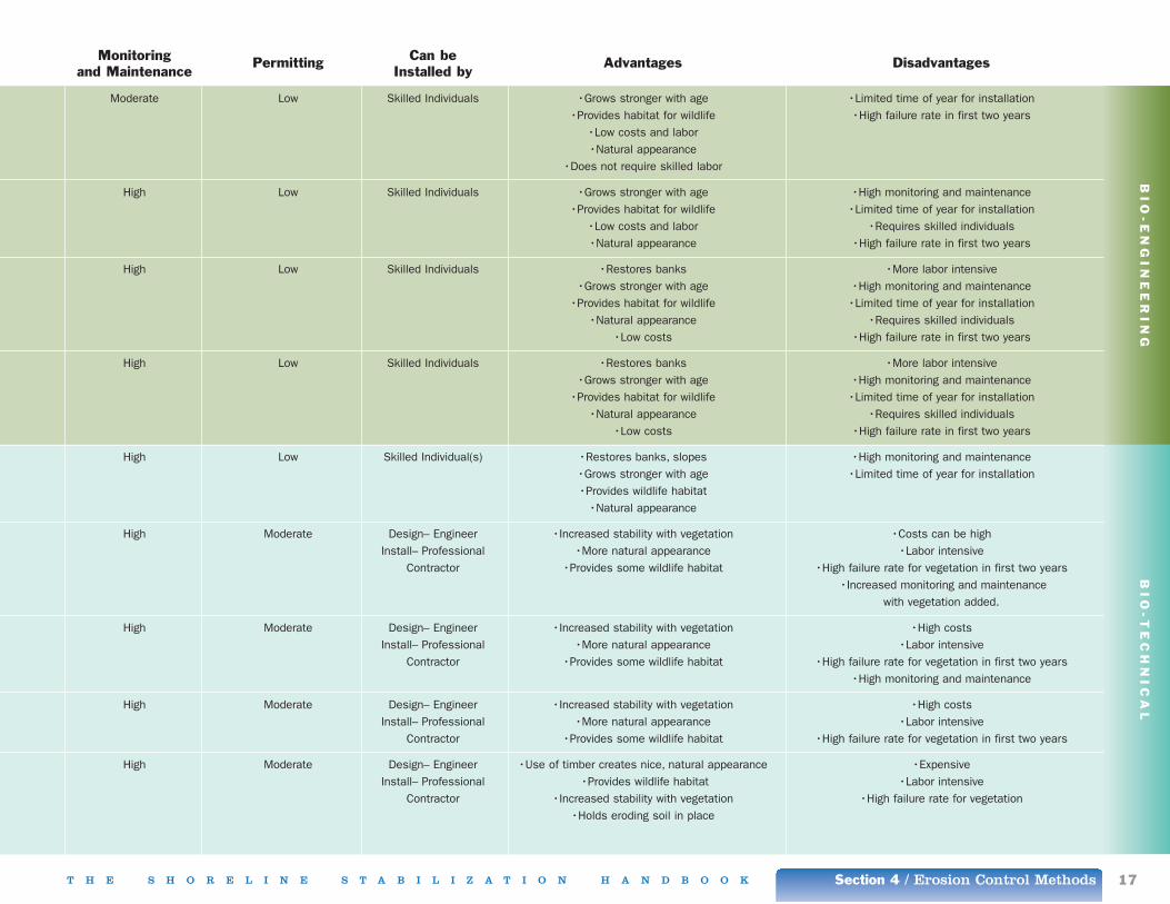
Monitoring Permitting Can be Advantages Disadvantagesand Maintenance Installed by
Moderate Low to None Skilled Individuals •Low costs and labor •Limited time of year for installation of native species•Aesthetically pleasing •High failure rate in first two years
•Grows stronger with age •Additional re-seeding may be necessary each year•Provides wildlife habitat
None Moderate Design– Engineer •Removes future problems •Costs can be highInstall– Professional •No monitoring and maintenance •Improper setback distance may result in future problems
Contractor •Requires heavy equipment •Requires significant land preparation
Moderate Moderate to Intensive Design– Engineer •Re-directs water flow •Can be expensiveInstall– Professional •Drainage structures are barely visible •May require significant land preparation
Contractor •May create problem elsewhere
Moderate Moderate Design– Engineer •Proven to be successful •Not aesthetically pleasingInstall– Professional •Less expensive than other •Costs can be high
Contractor structural methods •Creates barrier for fish and wildlife habitat•Weakens with age
High Moderate Design– Engineer •Can be built without heavy •Not aesthetically pleasingInstall– Professional equipment •Costs can be high
Contractor •Supports vegetation •Creates barrier wildlife•High maintenance and repair
•Weakens with age
Moderate Intensive Design– Engineer •Strong, durable structure •ExpensiveInstall– Professional •Works well against heavy waves •Not aesthetically pleasing
Contractor •Creates barrier for wildlife habitat•Does not support vegetation
•Weakens with age
High Moderate Design– Engineer •Resists heavy waves •ExpensiveInstall– Professional •Supports vegetation •Not aesthetically pleasing
Contractor •Creates barrier for wildlife•Weakens with age
Moderate Moderate Design– Engineer •Holds eroding soil in place •ExpensiveInstall– Professional •Can support some vegetation •Not aesthetically pleasing
Contractor •Weakens with age•Labor intensive
Moderate Not Permittable Design– Engineer •Essentially non-moving shoreline •Not aesthetically pleasingInstall– Professional •Need long reaches
Contractor •Takes up a lot of space
Moderate Intensive Design– Engineer •Reduces wave action •Boat hazardInstall– Professional •Environmental hazard
Contractor
NO
N-S
TR
UC
TU
RA
LS
TR
UC
TU
RA
L
T H E S H O R E L I N E S T A B I L I Z A T I O N H A N D B O O K Section 4 / Erosion Control Methods 15

Erosion Control Where It Works Where It Neighboring Labor/Preparation CostMethod Doesn’t Work Impacts
Live Staking On slopes where erosion is minimal. Badly eroded areas Low Low Lowpage26 Commonly used in conjunction with
other methods
Contour Wattling On slopes where erosion is minimal Badly eroded areas that Low Low Lowpage27 Top of a slope to provide a buffer zone receive heavy erosive action
Brush Layering On badly eroded slopes which need Loose soils Low Moderate Lowpage28 to be restored Heavy wave action
Brush Matting On badly eroded slopes which need Loose soils Low Moderate Lowpage29 to be restored Heavy wave action
Erosion Control Matting Moderate to steep slopes along Heavy wave action Low Moderate Lowpage31 roadways or on slopes
Vegetated Riprap Waterways or inland lakes where Steep banks with loose soil Moderate High Moderate to Highpage31 the underlying soil is stable
Vegetated Gabion Wall Moderate slopes to resist wave Steep slopes Moderate High Highpage32 action Loose soil
Vegetated Gabion Mattress Moderate slopes to resist wave Steep slopes Moderate High Highpage33 action, ice, and surface erosion Loose soil
Vegetated Cribbing Unvegetated slopes with a lot of backfill Steep slopes Moderate Moderate Moderate to High(Live Cribbing) and little wave action Heavy wave actionpage34
BIO
-EN
GIN
EE
RIN
GB
IO
-TE
CH
NIC
AL
Section 4 / Erosion Control Methods16 T H E S H O R E L I N E S T A B I L I Z A T I O N H A N D B O O K
Monitoring Permitting Can be Advantages Disadvantagesand Maintenance Installed by
Moderate Low Skilled Individuals •Grows stronger with age •Limited time of year for installation•Provides habitat for wildlife •High failure rate in first two years
•Low costs and labor•Natural appearance
•Does not require skilled labor
High Low Skilled Individuals •Grows stronger with age •High monitoring and maintenance•Provides habitat for wildlife •Limited time of year for installation
•Low costs and labor •Requires skilled individuals •Natural appearance •High failure rate in first two years
High Low Skilled Individuals •Restores banks •More labor intensive•Grows stronger with age •High monitoring and maintenance
•Provides habitat for wildlife •Limited time of year for installation•Natural appearance •Requires skilled individuals
•Low costs •High failure rate in first two years
High Low Skilled Individuals •Restores banks •More labor intensive•Grows stronger with age •High monitoring and maintenance
•Provides habitat for wildlife •Limited time of year for installation•Natural appearance •Requires skilled individuals
•Low costs •High failure rate in first two years
High Low Skilled Individual(s) •Restores banks, slopes •High monitoring and maintenance•Grows stronger with age •Limited time of year for installation•Provides wildlife habitat
•Natural appearance
High Moderate Design– Engineer •Increased stability with vegetation •Costs can be highInstall– Professional •More natural appearance •Labor intensive
Contractor •Provides some wildlife habitat •High failure rate for vegetation in first two years•Increased monitoring and maintenance
with vegetation added.
High Moderate Design– Engineer •Increased stability with vegetation •High costsInstall– Professional •More natural appearance •Labor intensive
Contractor •Provides some wildlife habitat •High failure rate for vegetation in first two years •High monitoring and maintenance
High Moderate Design– Engineer •Increased stability with vegetation •High costsInstall– Professional •More natural appearance •Labor intensive
Contractor •Provides some wildlife habitat •High failure rate for vegetation in first two years
High Moderate Design– Engineer •Use of timber creates nice, natural appearance •ExpensiveInstall– Professional •Provides wildlife habitat •Labor intensive
Contractor •Increased stability with vegetation •High failure rate for vegetation•Holds eroding soil in place
T H E S H O R E L I N E S T A B I L I Z A T I O N H A N D B O O K Section 4 / Erosion Control Methods 17
BIO
-EN
GIN
EE
RIN
GB
IO
-TE
CH
NIC
AL

Section 4 / Erosion Control Methods18 T H E S H O R E L I N E S T A B I L I Z A T I O N H A N D B O O K
Non-Structural and Preventative Options
As a natural process, erosion is not always aproblem. First and foremost, consider the effect ofdoing nothing. In some instances a “do nothing”or preventative approach may be the appropriatesolution. Doing nothing may be the best solutionwhere:
• erosion does not threaten valuable structures • these structures can be relocated• erosion is possibly part of a natural process
such as supplying sand to a beach• the erosion is proceeding at a slow rate and
may be considered “natural”
Where erosion is minor along the shores of thelake, implementing one or several non-structural orpreventative options may be most effective and
should always be considered before any other stabilization method is used.
These are the most common non-structural andpreventative methods:
Land Use PlanningUsing comprehensive site planning and design
principles whenever possible helps to preserveand maintain the integrity of natural shorelines.Using site planning and design principles is notlimited to municipalities, counties, and developers;individual property owners or several owners work-ing together can use site planning and design topreserve or enhance the integrity of a shoreline.Land use management and planning can preventinadvertent erosion and can be a very cost effec-tive approach to shoreline stabilization. Land useplanning:
• represents a link between shoreline stabilizationand protection, and economic development
• accomplishes environmental preservation andenhancement as well as socioeconomic objec-tives
• identifies areas of shoreline with no erosion orwith naturally-progressing erosion that should bemaintained
• identifies existing or potential shoreline erosionproblems needing attention, and
• defines specific measures for managing shore-line erosion
These goals and measures are often incorpo-rated as objectives within state and local land-useplanning programs.
Environmental management is frequently imple-mented through local plans, ordinances, zoningand site development review criteria. The intensity,type, and general design of planned developmentprojects can be managed to minimize changes tolakeshore properties. For instance, setbacks com-bined with preservation of a buffer of naturalvegetation will protect a shoreline from erosiondue to clearing and grading.
Public EducationThis cost effective method involves increasing
awareness by the general public and specificallylocal governments, developers, and property own-ers about what is being done and can be done to:
• preserve the natural shoreline • mitigate the impact of erosion• improve the water quality in Lake Champlain
Public interest in shoreline erosion will lead tomore widely available information sources regardingerosion and shoreline property management andcontrol at libraries, in brochures and on websites.
T H E S H O R E L I N E S T A B I L I Z A T I O N H A N D B O O K Section 4 / Erosion Control Methods 19
Re-Vegetation with Native SpeciesIn most cases where a bank or slope is dis-
turbed but not severely threatened by erosion,simple re-seeding or re-planting of native speciesis all it takes to stabilize the shoreline. This mayrequire grasses or sedges, shrubs, and trees.Woody vegetation, in particular, provides excellentnatural stabilization due to the deep roots thatthey produce. The most effective plant-basedshoreline stabilization is a multi-layered strip thatincludes trees, shrubs, and ground covers (nomown areas) to help minimize future loss of land.The highest success rate occurs when transplant-ing is done in late fall through early spring. Inmost cases, planting in the fall will be most con-venient since that is also the typical seasonallow-water level in the lake; it also gives the plantsan opportunity to establish roots under insulatingsnow cover.
“Native” species from other geographic areasare genetically different from local material andplanting non-native genetic material is compromis-ing Lake Champlain’s plant communities. In Vermont, by law, only native species can beused in plantings. The Intervale Foundation inBurlington, VT produces local native species for riparian restoration plantings. http://www.intervale.org/NNReparian.htm
Slope Crest Planting
The slope crest involves the area along theedge of the top of a bank or slope. This area is aprotective layer for the slope face and provides abuffer zone between the slope and any upland res-idential structures. The slope crest is importantwhere the slope is too steep and shoreline stabi-lization cannot be attempted. If a dense strip ofvegetation is planted in this area it will strengthen
TREES
Balsam fir
Striped maple
Red maple
Silver maple
Sugar maple
Serviceberry
Yellow birch
White birch
Grey birch
American hornbeam
American beech
White ash
Larch
Hop hornbeam
White spruce
White pine
Balsam poplar
Quaking aspen
Pin cherry
Black cherry
White oak
Swamp white oak
Bur oak
Red oak
White cedar
Basswood
Eastern hemlock
SHRUBS
Speckled alder
Bog rosemary
Bearberry
Black chokeberry
Buttonbush
Sweet fern
Beaked hazelnut
Pagoda dogwood
Red-osier dogwood
Bush honeysuckle
Wintergreen
Witch-hazel
Winterberry
Sheep laurel
Bog laurel
Canada (wild) plum
Chokecherry
Rhodora
Roseshell azalea
Staghorn sumac
Willow
Elderberry
Red elderberry
Mountain ash
Meadowsweet
Steeplebush
American yew
Lowbush blueberry
Hobblebush
Witherod
Arrowwood
Nannyberry
Highbush cranberry
FERNS AND VINES
Maidenhair
Ebony spleenwort
Maidenhair spleenwort
Lady fern
American bittersweet
Bulbet fern
Hayscented fern
Goldie’s wood fern
Evergreen wood fern
Ostrich fern
Sensitive fern
Cinnamon fern
Royal fern
Virginia creeper
Christmas fern
Braun’s holly fern
New York (tapering) fern
Rusty woodsia
HERBACEOUSPLANTS
Sweet flag
Spikenard
Baneberry
Common columbine
Wild ginger
Water arum
Marsh marigold
Harebell
Turtlehead
Bunchberry
Crowberry
Trailing arbutus
Joe-pyeweed
Blue flag iris
Creeping snowberry
Soft rush
Cardinal flower
Pickerelweed
Pitcher plant
False Solomon’s seal
Foamflower
Red trillium
White trillium
Bellwort
Blue vervain
Canada violet
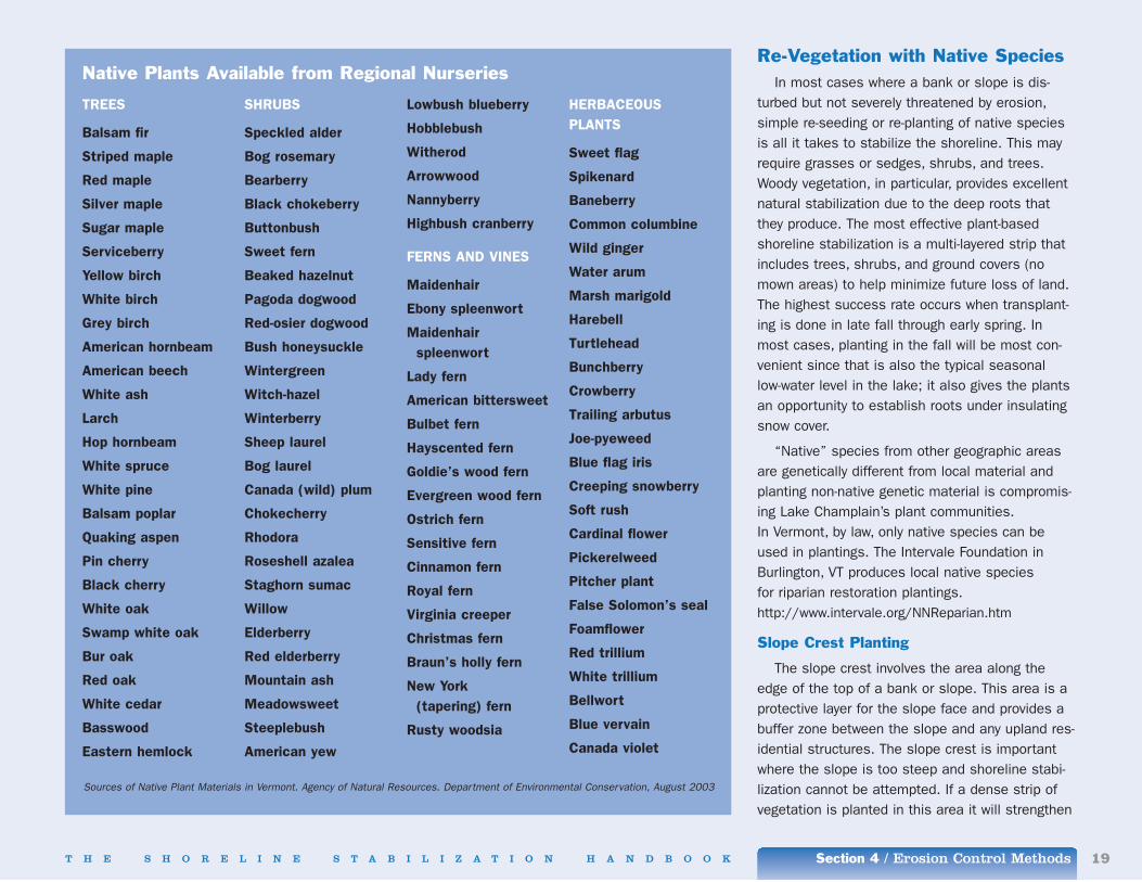
Native Plants Available from Regional Nurseries
Sources of Native Plant Materials in Vermont. Agency of Natural Resources. Department of Environmental Conservation, August 2003
Section 4 / Erosion Control Methods20 T H E S H O R E L I N E S T A B I L I Z A T I O N H A N D B O O K
the face of the slope and help protect from futureslumping or sliding. Any existing vegetation shouldbe left undisturbed on the slope crest. Plants thatcan be grown in this area if no or very little vegeta-tion is present include grasses and shrubs.
Slope Face Planting
The slope face is the flat steep surface on theslope. A wide variety of plant species can succeedon slope faces. Generally grasses, legumes, willows(shrubs and trees), dogwoods, alders, and poplarsare the best plant species for slope face planting.These plants are “pioneer species,” meaning theyare usually the first native species to grow in anarea. They usually grow fast, vigorously, and inabundance.
Trees growing on eroded slopes should be mon-itored. If the trees fall over due to undermining orslumping slopes, they will disturb a large amountof soil when the root mass is pulled up. If thereare existing trees on a slope, they should beexamined for signs of undercutting and toppling.Trees can be removed if these signs indicate treesare going to topple over imminently. It should benoted that trees that have fallen into the lake pro-vide valuable fish habitat and do not necessarilyneed to be removed.
Slope Toe Planting
The slope toe is the area where the slope faceflattens out. If the slope toe is subject to frequentwave action, plantings of live vegetation are mostlikely not going to survive and will not provide thebest means of stability. If the toe is not subject to heavy erosion, then trees and woody shrubsprovide excellent upland stability.
It is important to use only native vegetation;non-native species are becoming a serious
problem in the Lake Champlain Basin. A listing ofnative and non-native species can be found on thepreceding page of this handbook.
DrainageGullies are commonly seen along the banks of
Lake Champlain. Where erosion is caused byrunoff, often it can be intercepted and retained,dispersed, or simply better controlled using thesedrainage structures:
• a berm, or mound of earth placed along the topof a bank to stabilize a slope by interceptingwater and sediment from surface runoff. Bermsallow vegetation to re-establish in the area inwhich the gully formed. Caution is needed withthis approach, however, to ensure redirectedwater does not cause erosion in a new location
• dispersion and infiltration of water into vege-tated areas before it reaches the shoreline
• a pipe or stabilized ditch down the face of abank to transport the water
• an interceptor drain, where groundwater isdiverted into a discharge pipe to the lake. Thisis a more difficult option and a permit may berequired
Improving drainage is fairly inexpensive. A pro-fessional should assist in all drainage work sothat the water discharge does not cause futureproblems.
RelocationThis method relies heavily on the type of struc-
ture(s) being threatened by the loss of propertyfrom erosion. Structures include buildings, road-ways, septic systems, and water lines. Comparedwith the other non-structural stabilization and prevention options discussed, this is the mostexpensive due to separate costs for moving and
developing a new structure that may require newutilities and services.
The option of relocation versus constructingshoreline protection must be weighed against therisk of failure. Depending on the type of struc-ture(s) considered for relocation, it might be morecost effective to relocate than to install erosionprotection along the shore. It is important to lookat the condition of the structure(s) to be moved,any underlying foundation associated with it, anyobstructions and overall access to the land, andthe distance to be moved. If relocation is chosen,the structure(s) must be moved as far away aspossible from the shoreline to make sure that erosion will never threaten the structure(s) again.The local zoning administrator must be contactedto determine the minimum setback distance fromthe shoreline. A professional mover should be contacted to plan for moving a building.

T H E S H O R E L I N E S T A B I L I Z A T I O N H A N D B O O K Section 4 / Erosion Control Methods 21
Structural InstallationsA structural installation protects areas against
severe soil erosion on steep to moderately steepbanks and may be necessary to protect invest-ments that cannot be relocated. They are mostcommon along roadways, lakeshores, and streambanks and are built to resist wave action. Beforethe selection of a structural method is made,consider methods that will use or incorporate vegetation for their aesthetic, habitat and longevitybenefits.
Several types of structural installations havebeen built along Lake Champlain shorelines. Eachaddresses specific erosion management require-ments and are more suitable for certain areasthan others. Structural methods have similardesigns and typically require professional assis-tance and heavy equipment or extensive labor forconstruction. The following is an overview of struc-tural methods commonly used on the lake tomanage shoreline erosion, the materials used ineach method, a breakdown of the steps neededfor proper installation, and the approximate cost of installation.
RevetmentsA revetment uses stone or concrete and is
composed of three layers: an armor layer, a filter,and a toe.
The armor layer provides the most resistanceand stability against wave action and is usuallycomposed of rough, angled stone (riprap). The sizeof the material used will vary depending on thesteepness of the slope and the energy of thewaves to be resisted. The thickness of the armorlayer around a lake should be at least 27 inches.It is important to mix smaller materials with larger
materials to ensure the small cracks in the layerare filled. The determination of what size materialto use is usually based on the approximate waveheight to which a property is subjected. An engi-neer should be consulted to determine theappropriate size material to use.
The filter layer provides support to the armorlayer and allows for movement of water throughthe structure. It consists of a special filter fabriccalled a geotextile or six inches of well-gradedstone.
The toe is located at the lowest point of therevetment. It supports and anchors the structure,minimizing movement.
Revetments are used along waterways or inlandlakes to minimize shoreline or bank erosion. Theyare generally not installed on steep slopes. Allrevetments should be installed when water levelsare at the lowest point, usually during the fallmonths.
Two types of revetments are used on LakeChamplain:
Stone Riprap
Stone riprap is the most com-mon method used in the UnitedStates and one of the most versa-tile and effective means of bankprotection. It involves placing alayer of stones and boulders alonga slope face or bank and preventserosion and mass-movementcaused by wave action, ice, andsurface erosion.
To begin installation of a stoneriprap revetment, the groundshould be graded to achieve a
slope no steeper than 1.5 feet horizontal to 1 footvertical rise and no flatter than 2 feet horizontalfor every one foot of vertical rise. Clean, well-graded fill material should be added to achieve a uniform grade. Fill should not consist of stoneslarger than six inches and should be firmly com-pacted before construction begins.
It is recommended to use a filter fabric, when-ever possible. If using a stone mix, it should becomposed of stones ranging up to 3 inches in
A stone riprap revetment combines smaller placedrocks on the face of the bank and larger rocks to helpstabilize the toe of the bank near the waterline.
Stone Riprap Revetment Filter layer to support armor and preventunderlying soil from being washed away
Armor layer provides erosionprotection against wave action
Wave
Toe prevents displacement
GR
IFFI
NIN
TER
NA
TIO
NA
L, I
NC
.
Section 4 / Erosion Control Methods22 T H E S H O R E L I N E S T A B I L I Z A T I O N H A N D B O O K
diameter with very few fines. If a filter fabric isused, it is helpful to build a small stone layer inbetween the filter cloth and the armor layer. Therevetment can be constructed three different ways:hand placed, end-dumped, or placed by a derrickcrane. In most cases, graded rock and stones orconcrete are end-dumped on the site and thenrearranged in proper size sequence. When con-structing a revetment against heavy wave action,a derrick crane is often used to place larger mate-rials. The choice of construction will depend onthe size of material being used.
If machinery is needed to build a riprap revet-ment, the installation cost will most likely fall inthe range of $30 to $55 per linear foot for a struc-ture that is approximately 25-50 feet in width.
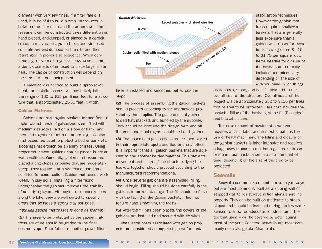
Gabion Mattress
Gabions are rectangular baskets formed from atriple twisted mesh of galvanized steel, filled withmedium size rocks, laid on a slope or bank, andthen tied together to form an armor layer. Gabionmattresses are used to protect a bed or bank of aslope against erosion on a variety of sites. Usingproper equipment, gabions can be placed in dry orwet conditions. Generally, gabion mattresses areplaced along slopes or banks that are moderatelysteep. They require a firm soil foundation and asolid toe for construction. Gabion mattresses workideally in clay soils. Installing a filter fabricunder/behind the gabions improves the stability of underlying layers. Although not commonly seenalong the lake, they are well suited to specificareas that possess a strong clay soil base.
Installing gabion mattresses is done as follows:
(1) The area to be protected by the gabion mat-tress structure should be graded to the finaldesired slope. Filter fabric or another gravel filter
layer is installed and smoothed out across theslope.
(2) The process of assembling the gabion basketsshould proceed according to the instructions pro-vided by the supplier. The gabions usually comefolded flat, stacked, and bundled by the supplier.They should be bent into the design form and allthe ends and diaphragms should be tied together.
(3) The assembled gabion baskets are then placedin their appropriate spots and tied to one another.It is important that all gabion baskets that are adja-cent to one another be tied together. This preventsmovement and failure of the structure. Tying thebaskets together should proceed according to themanufacturer’s recommendations.
(4) Once several gabions are assembled, fillingshould begin. Filling should be done carefully in thegabions to prevent damage. The fill should be flushwith the facing of the gabion baskets. This mayrequire hand smoothing the facing.
(5) After the fill has been placed, the covers of thegabions are installed and secured with tie wires.
Installation costs associated with gabion proj-ects are considered among the highest for bank
stabilization techniques.However, the gabion mat-tress requires shallowerbaskets that are generallyless expensive than agabion wall. Costs for thesebaskets range from $1.10to $1.75 per square foot.Items needed for closure ofthe baskets are normallyincluded and prices varydepending on the size ofwire you need. Such things
as tiebacks, stone, and backfill also add to theoverall cost of the structure. Overall costs of theproject will be approximately $50 to $100 per linealfoot of area to be protected. This cost includes thebaskets, filling of the baskets, stone fill (if needed),and basket closure.
The development of revetment structuresrequires a lot of labor and in most situations theuse of heavy machinery. The filling and closure ofthe gabion baskets is labor intensive and requiresa large crew to complete either a gabion mattressor stone riprap installation in a short amount oftime, depending on the size of the area to be protected.
SeawallsSeawalls can be constructed in a variety of ways
but are most commonly built as a sloping wall orstepped wall to resist wave action along shorelineproperty. They can be built on moderate to steepslopes and should be installed during the low waterseason to allow for adequate construction of thetoe that usually will be covered by water duringmost of the year. Concrete seawalls are most com-monly seen along Lake Champlain.
Gabion Mattress
Wave
Laced together with steel wire ties
Gabion cells filled with medium stones
ToeIde
al slo
pe le
ss tha
n 2:1
T H E S H O R E L I N E S T A B I L I Z A T I O N H A N D B O O K Section 4 / Erosion Control Methods 23
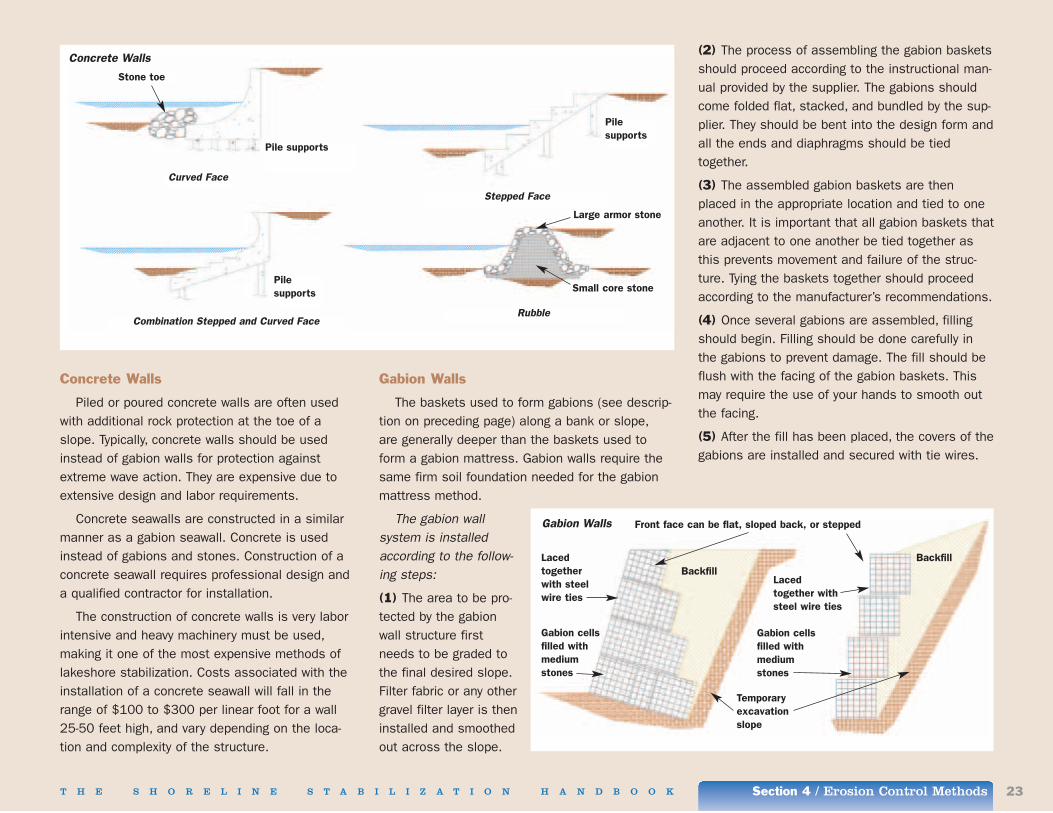
Concrete Walls
Piled or poured concrete walls are often usedwith additional rock protection at the toe of aslope. Typically, concrete walls should be usedinstead of gabion walls for protection againstextreme wave action. They are expensive due toextensive design and labor requirements.
Concrete seawalls are constructed in a similarmanner as a gabion seawall. Concrete is usedinstead of gabions and stones. Construction of aconcrete seawall requires professional design anda qualified contractor for installation.
The construction of concrete walls is very laborintensive and heavy machinery must be used,making it one of the most expensive methods oflakeshore stabilization. Costs associated with theinstallation of a concrete seawall will fall in therange of $100 to $300 per linear foot for a wall25-50 feet high, and vary depending on the loca-tion and complexity of the structure.
Gabion Walls
The baskets used to form gabions (see descrip-tion on preceding page) along a bank or slope,are generally deeper than the baskets used toform a gabion mattress. Gabion walls require thesame firm soil foundation needed for the gabionmattress method.
The gabion wall system is installedaccording to the follow-ing steps:
(1) The area to be pro-tected by the gabionwall structure firstneeds to be graded tothe final desired slope.Filter fabric or any othergravel filter layer is theninstalled and smoothedout across the slope.
(2) The process of assembling the gabion basketsshould proceed according to the instructional man-ual provided by the supplier. The gabions shouldcome folded flat, stacked, and bundled by the sup-plier. They should be bent into the design form andall the ends and diaphragms should be tiedtogether.
(3) The assembled gabion baskets are thenplaced in the appropriate location and tied to oneanother. It is important that all gabion baskets thatare adjacent to one another be tied together asthis prevents movement and failure of the struc-ture. Tying the baskets together should proceedaccording to the manufacturer’s recommendations.
(4) Once several gabions are assembled, fillingshould begin. Filling should be done carefully inthe gabions to prevent damage. The fill should beflush with the facing of the gabion baskets. Thismay require the use of your hands to smooth outthe facing.
(5) After the fill has been placed, the covers of thegabions are installed and secured with tie wires.
Pilesupports
Pile supports
Pilesupports
Large armor stone
Small core stone
Stone toe
Curved Face
Combination Stepped and Curved Face
Stepped Face
Rubble
Concrete Walls
Gabion Walls Front face can be flat, sloped back, or stepped
BackfillLacedtogetherwith steelwire ties
Gabion cellsfilled withmediumstones
Lacedtogether withsteel wire ties
Gabion cellsfilled withmediumstones
Backfill
Temporaryexcavationslope
Section 4 / Erosion Control Methods24 T H E S H O R E L I N E S T A B I L I Z A T I O N H A N D B O O K
As with the gabion mattress structure, costsassociated with gabion seawalls generally areamong the highest for bank stabilization and ero-sion control techniques. The cost of the gabionwall baskets range from $1.50 to $3.20 persquare foot for 3 foot deep baskets, $1.25 to$2.00 per square foot for 18 inch deep baskets,and $1.10 to $1.75 per square foot for 12 inchdeep baskets. Overall costs of the project will costapproximately $50 to $100 per linear foot of areato be protected. This cost includes the baskets,filling of the baskets, stone fill (if needed), andbasket closure.
BulkheadsThese retaining wall structures hold backfill
and prevent it from sliding, while providing protec-tion against moderate wave action. They are builtwhere the soil on a slope is eroding and needs to be secured. This method is suitable in areaswhere a large quantity of backfill is available andthe shoreline receives moderate wave action. They do not resist heavy wave action. They will protect un-vegetated, eroding high banks with amoderate slope. They should be installed duringthe low water season. These are the most com-monly used bulkhead structures:
Sheet Piles
These are used instead of seawallsin places where erosion has occurredover very steep slopes with high eleva-tion changes. They are not typicallyused for erosion control; rather, sheetpiles are used as a foundation forstructures such as buildings or docks.
Piles can be constructed of wood,concrete, steel, plastic, or a combina-tion of these materials. They are installed adjacentto one another to essentially create a vertical walladjacent to the water edge. A professional geo-technical engineer must plan the design of a sheetpiled system.
Installation of a sheet pile system generallyrequires heavy construction equipment and materials following this procedure:
(1) The shoreline is excavated and a vertical soilwall is created. Depending on soil conditions,a bank may need to be sloped back and laterbackfilled.
(2) Prefabricated piles are driven into the soilusing a pile-driving hammer. Cast-in-place piles areconstructed of concrete poured into auger-drilledholes in the ground.
(3) Backfill is placed behind the piles and topsoilis added, graded, and seeded.
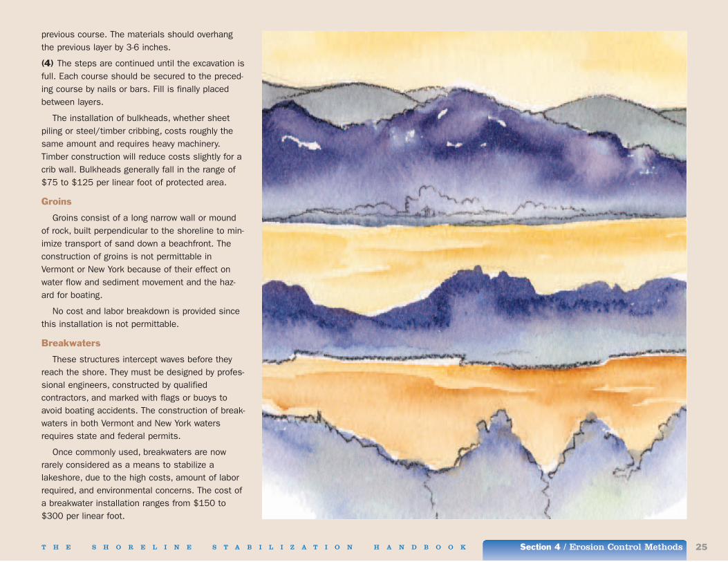
Steel/Timber Cribbing
Cribbing uses steel or timber-walled cells toform a box-like structure filled with rock or soil toadd strength. The cells can be formed several dif-ferent ways, but most commonly are built in a “logcabin” type style in which the steel or timber isstacked on to one another with a block of concreteplaced in between. Timber is more commonly used
than steel due to its availability and resistance tosalt and weathering. Rough-cut, structural-gradeDouglas fir is the most commonly used species of timber.
Construction of crib walls follows this procedure:
(1) Starting at the lowest point of the slope,material is excavated 2-3 feet below the groundsurface. The excavation should be at an incline of1:6 (Horizontal:Vertical).
(2) The first course of steel/timber/concrete isplaced at the front and back of the excavation,about five feet apart and parallel to the slope contour.
(3) The next course of material is placed perpendi-cular to the slope (at right angles) on top of the
Timber crib walls, typically constructed using Douglasfir, are not commonly built on Lake Champlain’sshores; they could be adapted as seawalls.
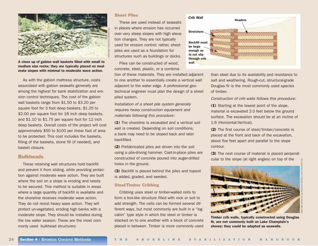
A close up of gabion wall baskets filled with small tomedium size rocks; they are typically placed on mod-erate slopes with minimal to moderate wave action.
Crib WallHeaders
Stretchers
Backfill mustbe largeenough as to not slipthrough cribwall
WW
W.D
MLL
.CO
M/P
ICS
_GA
BIO
N4
.JP
G
WW
W.S
BE
.NA
PIE
R.O
C.U
K/P
RO
JEC
TS/R
ETW
ALL
/HE
LP/S
OU
THP
RT.
GIF
T H E S H O R E L I N E S T A B I L I Z A T I O N H A N D B O O K Section 4 / Erosion Control Methods 25
previous course. The materials should overhangthe previous layer by 3-6 inches.
(4) The steps are continued until the excavation isfull. Each course should be secured to the preced-ing course by nails or bars. Fill is finally placedbetween layers.
The installation of bulkheads, whether sheet piling or steel/timber cribbing, costs roughly thesame amount and requires heavy machinery.Timber construction will reduce costs slightly for acrib wall. Bulkheads generally fall in the range of$75 to $125 per linear foot of protected area.
Groins
Groins consist of a long narrow wall or moundof rock, built perpendicular to the shoreline to min-imize transport of sand down a beachfront. Theconstruction of groins is not permittable inVermont or New York because of their effect onwater flow and sediment movement and the haz-ard for boating.
No cost and labor breakdown is provided sincethis installation is not permittable.
Breakwaters
These structures intercept waves before theyreach the shore. They must be designed by profes-sional engineers, constructed by qualifiedcontractors, and marked with flags or buoys toavoid boating accidents. The construction of break-waters in both Vermont and New York watersrequires state and federal permits.
Once commonly used, breakwaters are nowrarely considered as a means to stabilize alakeshore, due to the high costs, amount of laborrequired, and environmental concerns. The cost ofa breakwater installation ranges from $150 to$300 per linear foot.
Section 4 / Erosion Control Methods26 T H E S H O R E L I N E S T A B I L I Z A T I O N H A N D B O O K
Bioengineering Installations
Bioengineering dates back to 12th centuryChina. It has been widely used in Europe for over150 years and today increasingly throughout theUnited States. Bioengineering methods are not yetwidely used in the Lake Champlain region.However, the aesthetics, lower costs, and longer-term benefits to the shoreline and water qualitymake these methods well suited to this area.
Bioengineering stabilizes a bank and shorelinewhile improving fish and wildlife habitat. Thismethod works well in combination with structuralmethods; the combination is described as abiotechnical installation.
Bioengineering alone is generally not applied onsteep slopes and usually requires some shapingof a slope as part of the installation. Typically, pri-vate landowners use bioengineering methods insmall areas along a lake.
This method is most suitable in areas wheresite soils have adequate moisture, sufficient lightand drainage throughout the growing season so live vegetation can become fully established. A clay or loamy soil is more suitable for rootanchorage than rocky, sandy or silt soils. As notedelsewhere in this handbook, bioengineering shore-line erosion controls should be installed atseasonal low water on the lake and during the dormant growing season for the plants beingused. The selection of what types of plants andhow and when to harvest the plants to be used inyour installation is discussed in other areas ofSection 4. The most commonly used materials,installation methods and costs for bioengineeringinclude:
Live Staking
This is the easiest and least expensive bioengi-neering erosion control method to install. Livecuttings of certain species inserted into theground on a slope or shoreline will sprout rootsand new branches, eventually forming maturewoody plants. This method is limited to smallareas with minimal bank erosion damage. It ismost effective where shallow erosion hasoccurred, and when combined with other bioengi-neering methods, such as live fascine bundlingand brush matting (see pages 27 and 29). Thismethod does not require skilled labor to apply. Itcan be used in a number of different areas includ-ing the sides of gullies and across slopes.
The most commonly used plant species is thewillow; however, some species of dogwood or aldermay be used. (See page 19 for a list of native wil-low, dogwood or alder species.) The stakes should
be 0.25 to 1 inches in diameter and 2 to 3 feetlong. A dead blow hammer will be needed to drivethe live stakes down into the ground. These ham-mers are available at any hardware store. A steel bar may be necessary to form pilot holes in tightlycompacted soils.
Installation of a live staking system consists of thefollowing steps:
(1) The live stakes should be collected and pre-pared for installation. The stakes must be cut fromdormant, mature stems and used within 8-10 daysof being harvested. A supply of fresh cuttings shouldbe collected using a sharp pair of shears. The sidebranches should be trimmed making sure not todamage the bark. The stake should be cut to theneeded length (a minimum of 1 foot) and an anglecut should be made at the bottom. It is important tomake sure the angle cut is done at the bottom sothat the stake is not planted upside down.
Live Staking, and Live Staking with Contour Wattling and Native Species Planting
Live cuttingsLive cuttings
Stools of mixed grain,oats, wheats, orwoody transplants
Semi-compactedsub-surface material
Wattles of cut brush buriedin contour trenches
Loos
e slid
ing su
rface
laye
r
Planted tree or shrub

T H E S H O R E L I N E S T A B I L I Z A T I O N H A N D B O O K Section 4 / Erosion Control Methods 27
(2) The live stakes should be installed by using adead blow hammer. It is important to use a deadblow hammer as opposed to using a mallet sothat you minimize damage to the live stake. Thestake should be driven gently into the ground form-ing a right angle to the slope. If the soil is tightlycompacted, it may be necessary to create a pilothole by using a steel bar. It is important to makesure that the soil is packed around the live stakeif you have used a pilot hole. The live stakesshould be driven in so that approximately 70% ofthe stem is buried and 30% is exposed.
(3) The stakes should be installed 2 to 3 feetapart in a triangular pattern. There should be nomore than 2 to 4 stakes per square yard. Soilshould be firmly packed around the stakes.
Costs are minimized if the cuttings are col-lected from free sites and volunteer labor isprovided. However, in your planning assume thatlabor and plant materials will be purchased.Overall costs will range from $1.50 to $3.50 perstake.
Contour Wattling (Live Fascines)
Fascines are stems and branches from livewoody plants tied together in bundles. Plants thatwork best in the Lake Champlain climate are wil-low, red osier dogwood, and snowberry.
When placed in shallow trenches parallel to abank or shoreline, live fascines are called contourwattling. These bundles, held in place with woodenstakes, slow runoff and trap sediment. Live fascinesare commonly used with other methods to addstructural support to the toe of the bank. They aresuitable to protect the toe and face of a slopewhere erosion is primarily caused by stormwaterrunoff and the depth of erosion is approximately 6 to 8 inches. Riprap is the most commonly used
method to provide a stable toe. A live fascine bun-dle can also be grown on the top of the slope toact as a vegetative buffer zone.
Installing this method system requires skilled,experienced individuals and consists of the follow-ing steps:
(1) The live fascine bundles must be constructedusing fresh, live cut plant material. The cuttingsshould be straight and range from 0.25 to 1 inchin diameter and 5 to 30 feet in length dependingon the site conditions. Age, size and speciesshould be mixed throughout the bundle with thegrowing tips of the cuttings facing in the samedirection. It is okay to keep the side brancheswhen forming a live fascine bundle. The cuttingsshould be mixed together until the bundle isapproximately 6 to 8 inches in diameter whensecurely tied. The bundles can be tied with hemp
binder twine or by wrapping “pigtails.” A tie shouldbe placed every foot with a non-slipping knot suchas a square knot.
(2) Trenches should be dug at the base of a slopeand should be just large enough in width to hold afascine bundle. The depth should be about halfthe size of the bundle.
(3) The bundles should be placed in the newly dugtrench and secured using a wooden stake approxi-mately 2 to 3 feet long. The stakes, pounded intothe bundle and ground using a heavy hammer,should be spaced every 2 to 3 feet along thelength of the bundles and driven down so thatthere are 2 to 3 inches remaining above the top ofthe bundle.
(4) Moist topsoil should be placed in and alongthe sides of the bundles. It is important to notfully bury the fascines; a few twigs or leaves
Contour Wattling
8"- 10"
12"- 15"
Twine Live branches
Prepare wattling,cigar shapes bundlesof live brush withends alternating, 8"- 10" diameter tied12"- 15" apart
1. Live plant stake on contour
2. Trench above stakes1/2 diameter of bundles
3. Place bundles in trench
4. Add dead stout stakesthrough and below bundles
5. Cover wattling with soil, tamp firmly
Live branches
Compactedfill material
Live stake
Dead stout stake

Section 4 / Erosion Control Methods28 T H E S H O R E L I N E S T A B I L I Z A T I O N H A N D B O O K
should penetrate through the layer of soil.
(5) Additional trenches should be dug up the slopeat an appropriate interval. Steps 3 and 4 shouldbe repeated until the slope is covered. A 3-footspacing interval is recommended between rows.
(6) Straw or mulch should be placed in betweenthe rows on flatter slopes and a jute or coir fabricon steeper slopes. The fabric can be held in placeby running the ends of it into the trenches andstaking the fascine through the fabric.
Costs associated with the construction of thistype of installation are generally minimal. For thetypical 6 to 8 inch live fascine bundles, costsrange from $10.00 to $30.00 per foot. This priceincludes twine, securing devices for installation,harvesting, transportation, handling, fabrication,storage, excavation, backfill, and compaction. Aswith all stabilization techniques, costs will varydepending on design, access to site location, timeof year, and labor rates. Installation is relativelysimple because heavy equipment is not neededexcept to prepare the slope of the bank.
Brush Layering
This involves using cut branches from livewoody plants and dispersing them between layersof soil along a shoreline or bank to create a seriesof benches. Long, dormant live branches from wil-low, alder, and dogwood are most commonly usedto provide extra strength and reinforcement for thesoil or fill along a slope or bank. This method ismost commonly used in replacing new fill, restor-ing shallow slumps, and repairing narrow gullies. Itprovides future erosion protection and stabilizationto loose soil slopes, can be used on either cut(natural) or filled slopes, and works best whencombined with natural “geofabrics” or synthetic“geogrids.”
Skilled individuals should install a brush layeringsystem. Beginning at the base of the slope andworking upwards:
(1) Long branches should be cut from your chosenplant species. The length of the branches canrange up to 12 feet and should be approximately0.25 to 1 inch in diameter. A supply of fresh, dor-mant cuttings should be collected and trimmed ofalmost all branches.
(2) The first bench should be excavated at thebottom of the slope. The face surface of thebench should angle back into the slope approxi-mately 10-25 degrees off horizontal.
(3) The first layer of cuttings should be placed onthe bench making sure all the cut ends are touch-ing the back of the excavated area and the tips ofthe branches are pointing out of the slope. The
cuttings should be crisscrossed with the first layerbeing approximately 1 inch thick.
(4) Dry, light soil placed on the cuttings should fillany cracks or air voids in the layer. The next layerof cuttings should be placed on top of this layerand the process should be repeated until thereare several different layers.
(5) Steps 1 through 4 should be repeated as youmove up the slope. It will be helpful to build twobenches at once and to move the soil from theupslope bench onto the cuttings on the lowerbench.
(6) Mulch or straw should be placed on the soilbetween benches.
In situations where there has been heavy ero-sion on a bank, covering soil is usually filled in thebench areas by machinery.
Brush Layering Rooted plants
3'-9'
Maxslope1:1
1/3 2/3
10˚
Edge of fill3'
Plan view
Compacted fill material
Plantcuttings
4.5' - 9'
1/4 3/4
10˚
Maxslope1:1 Min. 1.5'
Low toe wallconstructed oftimber, stone,or gabion
Plant cuttings
Back fill
5'
Required verticalbench spacing (Y) tomaintain 1:1 slopeabove bench duringexcavation
Y
Y
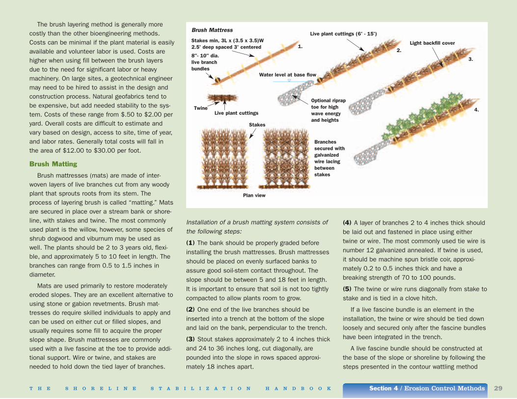
T H E S H O R E L I N E S T A B I L I Z A T I O N H A N D B O O K Section 4 / Erosion Control Methods 29
The brush layering method is generally morecostly than the other bioengineering methods.Costs can be minimal if the plant material is easilyavailable and volunteer labor is used. Costs arehigher when using fill between the brush layersdue to the need for significant labor or heavymachinery. On large sites, a geotechnical engineermay need to be hired to assist in the design andconstruction process. Natural geofabrics tend tobe expensive, but add needed stability to the sys-tem. Costs of these range from $.50 to $2.00 peryard. Overall costs are difficult to estimate andvary based on design, access to site, time of year,and labor rates. Generally total costs will fall inthe area of $12.00 to $30.00 per foot.
Brush Matting
Brush mattresses (mats) are made of inter-woven layers of live branches cut from any woodyplant that sprouts roots from its stem. Theprocess of layering brush is called “matting.” Matsare secured in place over a stream bank or shore-line, with stakes and twine. The most commonlyused plant is the willow, however, some species ofshrub dogwood and viburnum may be used aswell. The plants should be 2 to 3 years old, flexi-ble, and approximately 5 to 10 feet in length. Thebranches can range from 0.5 to 1.5 inches indiameter.
Mats are used primarily to restore moderatelyeroded slopes. They are an excellent alternative tousing stone or gabion revetments. Brush mat-tresses do require skilled individuals to apply andcan be used on either cut or filled slopes, andusually requires some fill to acquire the properslope shape. Brush mattresses are commonlyused with a live fascine at the toe to provide addi-tional support. Wire or twine, and stakes areneeded to hold down the tied layer of branches.
Installation of a brush matting system consists ofthe following steps:
(1) The bank should be properly graded beforeinstalling the brush mattresses. Brush mattressesshould be placed on evenly surfaced banks toassure good soil-stem contact throughout. Theslope should be between 5 and 18 feet in length.It is important to ensure that soil is not too tightlycompacted to allow plants room to grow.
(2) One end of the live branches should beinserted into a trench at the bottom of the slopeand laid on the bank, perpendicular to the trench.
(3) Stout stakes approximately 2 to 4 inches thickand 24 to 36 inches long, cut diagonally, arepounded into the slope in rows spaced approxi-mately 18 inches apart.
(4) A layer of branches 2 to 4 inches thick shouldbe laid out and fastened in place using eithertwine or wire. The most commonly used tie wire isnumber 12 galvanized annealed. If twine is used,it should be machine spun bristle coir, approxi-mately 0.2 to 0.5 inches thick and have abreaking strength of 70 to 100 pounds.
(5) The twine or wire runs diagonally from stake tostake and is tied in a clove hitch.
If a live fascine bundle is an element in theinstallation, the twine or wire should be tied downloosely and secured only after the fascine bundleshave been integrated in the trench.
A live fascine bundle should be constructed atthe base of the slope or shoreline by following thesteps presented in the contour wattling method
Brush Mattress
Stakes min, 3L x (3.5 x 3.5)W2.5' deep spaced 3' centered
8"- 10" dia.live branchbundles
TwineLive plant cuttings
Live plant cuttings (6' - 15')
Water level at base flow
Optional ripraptoe for highwave energyand heights
Light backfill cover
Stakes
1.2.
3.
4.
Branchessecured withgalvanizedwire lacingbetweenstakes
Plan view
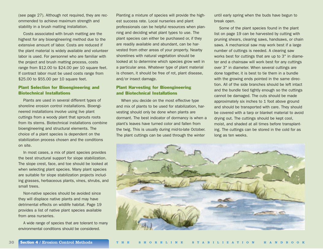
Section 4 / Erosion Control Methods30 T H E S H O R E L I N E S T A B I L I Z A T I O N H A N D B O O K
(see page 27). Although not required, they are rec-ommended to achieve maximum strength andstability in a brush matting installation.
Costs associated with brush matting are thehighest for any bioengineering method due to theextensive amount of labor. Costs are reduced ifthe plant material is widely available and volunteerlabor is used. For personnel who are familiar withthe project and brush matting process, costsrange from $12.00 to $24.00 per 10 square feet.If contract labor must be used costs range from$25.00 to $55.00 per 10 square feet.
Plant Selection for Bioengineering andBiotechnical Installations
Plants are used in several different types ofshoreline erosion control installations. Bioengi-neered installations involve using live plantcuttings from a woody plant that sprouts rootsfrom its stems. Biotechnical installations combinebioengineering and structural elements. Thechoice of a plant species is dependent on the stabilization process chosen and the conditions on site.
In most cases, a mix of plant species providesthe best structural support for slope stabilization.The slope crest, face, and toe should be looked atwhen selecting plant species. Many plant speciesare suitable for slope stabilization projects includ-ing grasses, herbaceous plants, vines, shrubs, andsmall trees.
Non-native species should be avoided sincethey will displace native plants and may have detrimental effects on wildlife habitat. Page 19provides a list of native plant species availablefrom area nurseries.
A wide range of species that are tolerant to manyenvironmental conditions should be considered.
Planting a mixture of species will provide the high-est success rate. Local nurseries and plantprofessionals can be helpful resources when plan-ning and deciding what plant types to use. Theplant species can either be purchased or, if theyare readily available and abundant, can be har-vested from other areas of your property. Nearbyshorelines with natural vegetation should belooked at to determine which species grow well ina particular area. Whatever type of plant materialis chosen, it should be free of rot, plant disease,and/or insect damage.
Plant Harvesting for Bioengineering and Biotechnical Installations
When you decide on the most effective typeand mix of plants to be used for stabilization, har-vesting should only be done when plants aredormant. The best indicator of dormancy is when aplant’s leaves have turned color and fallen fromthe twig. This is usually during mid-to-late October.The plant cuttings can be used through the winter
until early spring when the buds have begun tobreak open.
Some of the plant species found in the plantlist on page 19 can be harvested by cutting withpruning shears, clearing saws, handsaws, or chainsaws. A mechanical saw may work best if a largenumber of cuttings is needed. A clearing sawworks best for cuttings that are up to 3" in diame-ter and a chainsaw will work best for any cuttingsover 3" in diameter. When several cuttings aredone together, it is best to tie them in a bundlewith the growing ends pointed in the same direc-tion. All of the side branches should be left intactand the bundle tied tightly enough so the cuttingscannot be damaged. The cuts should be madeapproximately six inches to 1 foot above groundand should be transported with care. They shouldbe covered with a tarp or blanket material to avoiddrying out. The cuttings should be kept cool,moist, and shaded at all times before transplant-ing. The cuttings can be stored in the cold for aslong as ten weeks.

T H E S H O R E L I N E S T A B I L I Z A T I O N H A N D B O O K Section 4 / Erosion Control Methods 31
Biotechnical Biotechnical shoreline stabilization methods
combine the use of structural-mechanical materi-als and plants. The structural and biologicalmaterials work together to provide improved ero-sion control in areas of high wave energy or severeerosion while minimizing environmental impacts.Both the structural and biological materials providestability within the system and are suitable for awide range of areas. When properly installed, abiotechnical solution provides improved aestheticsover structural methods. It does require a greateramount of planning and is commonly used to prevent both surface erosion and shallow mass-movement of soil.
These methods should only be installed duringthe dormant plant growing season and low waterlevels. With the exception of live cribbing, the con-struction of biotechnical methods can be separatedinto structural and bioengineering installations. For best development and structural support, it isrecommended that they be constructed together.As with bioengineering methods, biotechnicalmethods are not yet widely used in the LakeChamplain region. However, the longer-term bene-fits to the shoreline and water quality make thesemethods well suited to this area and they shouldbecome more commonly used as awarenessincreases of their effectiveness and ability toblend into their surroundings.
The following is an overview of the materialsused for each biotechnical installation, the stepsneeded for proper implementation and an esti-mate of costs involved. Site conditions forbioengineered installations need to be consideredbefore the structural portions are installed.
Erosion Control Matting
Erosion control matting, made of lightweight,entangled nylon filaments, generally comes in rollsthat can be easily shipped, stored, and installed.
There are two options when installing erosioncontrol matting: soil filling or non-soil filling. Thematting is rolled out on a bank or slope and grassseeds are spread and planted throughout the mat-ting. Soil filling is usually done to provide topsoilfor the seeds to develop. This helps to reinforcethe plant roots. As the plant roots grow, theybecome intertwined with the matting, producing avery stable slope cover.
This method requires no heavy equipment forinstallation, and generally can be installed by oneperson. Other biodegradable and photodegradablefabrics and natural products such as coir fabriccan also be used. Erosion control matting is com-monly placed on banks, slopes, and along theedges of roadways.
Installation of an erosion control matting system isdone as follows:
(1) The slope must be properly shaped to designspecifications with all rocks and soil clumpsremoved.
(2) The matting, generally 3-4 feet wide, is rolleddown the slope overlapping 3-4 inches with eachsuccessive roll. Staples are installed down thecenter of each mat with 3 to 5 feet separating thestaples. For most slopes, 3 or 4 staples should beinstalled in every square yard.
(3) After the matting is anchored down with metalstaples and if the soil filling method is used, .5 to.75 inches of fine soil should be spread into themat, completely filling the spaces.
(4) Once the filling is complete, seeding should
occur. Seeding may occur before and after filling toincrease vegetation.
Costs associated with erosion control mattingare similar to the costs to install live staking whichis $1.50 to $3.00 per square yard. Costs are mini-mal due to minimal labor requirements and noneed for heavy machinery.
Vegetated Riprap (Joint Planting)
Vegetated riprap, often referred to as joint plant-ing, combines the use of a stone revetmentstructure and live plants. Live cut stakes approxi-mately 1 to 1.5 inches in diameter are placed inthe cracks or openings between the rocks. Thestakes need to be long enough to be able to reachthrough the armor and filter layers into the soil atthe base of the riprap. The cuttings from willowtrees tend to work best for this method. In amature installation, the roots of the plants provideadditional soil strength and the vegetation hidesthe rock creating a more scenic look. Vegetatedriprap is primarily used along waterways or inlandlakes.
Vegetated Riprap Existing slope surface
3'- 4' long, 2" diameterlive cuttings
Existing or new rockor riprap surface
3"- 4"protrude
18"min.
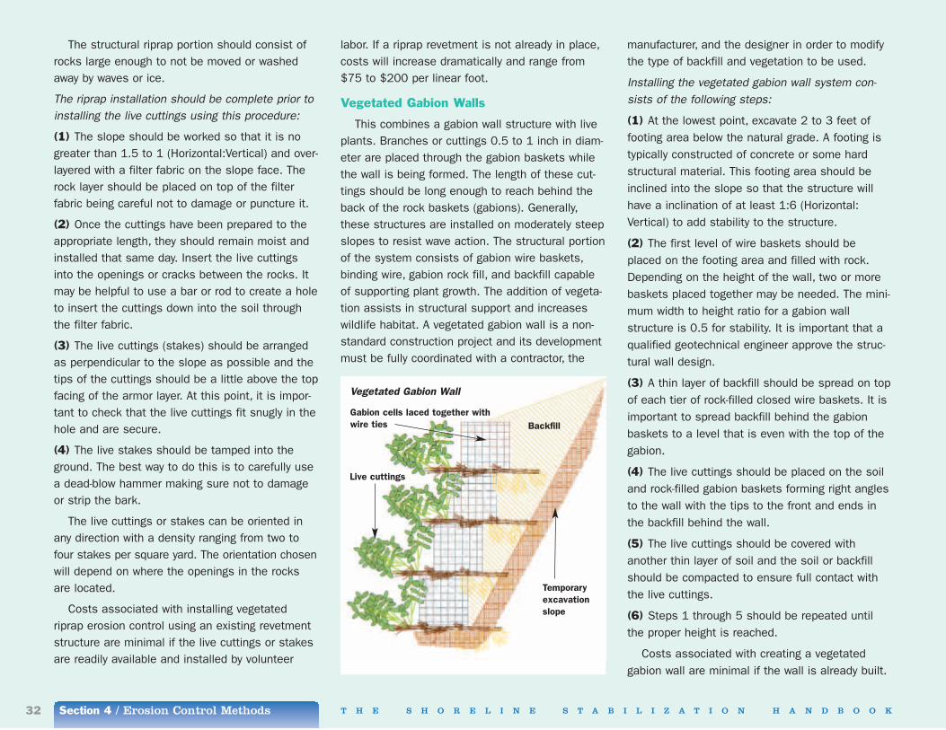
Section 4 / Erosion Control Methods32 T H E S H O R E L I N E S T A B I L I Z A T I O N H A N D B O O K
The structural riprap portion should consist ofrocks large enough to not be moved or washedaway by waves or ice.
The riprap installation should be complete prior toinstalling the live cuttings using this procedure:
(1) The slope should be worked so that it is nogreater than 1.5 to 1 (Horizontal:Vertical) and over-layered with a filter fabric on the slope face. Therock layer should be placed on top of the filter fabric being careful not to damage or puncture it.
(2) Once the cuttings have been prepared to theappropriate length, they should remain moist andinstalled that same day. Insert the live cuttingsinto the openings or cracks between the rocks. Itmay be helpful to use a bar or rod to create a holeto insert the cuttings down into the soil throughthe filter fabric.
(3) The live cuttings (stakes) should be arrangedas perpendicular to the slope as possible and thetips of the cuttings should be a little above the topfacing of the armor layer. At this point, it is impor-tant to check that the live cuttings fit snugly in thehole and are secure.
(4) The live stakes should be tamped into theground. The best way to do this is to carefully usea dead-blow hammer making sure not to damageor strip the bark.
The live cuttings or stakes can be oriented inany direction with a density ranging from two tofour stakes per square yard. The orientation chosenwill depend on where the openings in the rocksare located.
Costs associated with installing vegetatedriprap erosion control using an existing revetmentstructure are minimal if the live cuttings or stakesare readily available and installed by volunteer
labor. If a riprap revetment is not already in place,costs will increase dramatically and range from$75 to $200 per linear foot.
Vegetated Gabion Walls
This combines a gabion wall structure with liveplants. Branches or cuttings 0.5 to 1 inch in diam-eter are placed through the gabion baskets whilethe wall is being formed. The length of these cut-tings should be long enough to reach behind theback of the rock baskets (gabions). Generally,these structures are installed on moderately steepslopes to resist wave action. The structural portionof the system consists of gabion wire baskets,binding wire, gabion rock fill, and backfill capableof supporting plant growth. The addition of vegeta-tion assists in structural support and increaseswildlife habitat. A vegetated gabion wall is a non-standard construction project and its developmentmust be fully coordinated with a contractor, the
manufacturer, and the designer in order to modifythe type of backfill and vegetation to be used.
Installing the vegetated gabion wall system con-sists of the following steps:
(1) At the lowest point, excavate 2 to 3 feet offooting area below the natural grade. A footing istypically constructed of concrete or some hardstructural material. This footing area should beinclined into the slope so that the structure willhave a inclination of at least 1:6 (Horizontal:Vertical) to add stability to the structure.
(2) The first level of wire baskets should beplaced on the footing area and filled with rock.Depending on the height of the wall, two or morebaskets placed together may be needed. The mini-mum width to height ratio for a gabion wallstructure is 0.5 for stability. It is important that aqualified geotechnical engineer approve the struc-tural wall design.
(3) A thin layer of backfill should be spread on topof each tier of rock-filled closed wire baskets. It isimportant to spread backfill behind the gabionbaskets to a level that is even with the top of thegabion.
(4) The live cuttings should be placed on the soiland rock-filled gabion baskets forming right anglesto the wall with the tips to the front and ends inthe backfill behind the wall.
(5) The live cuttings should be covered withanother thin layer of soil and the soil or backfillshould be compacted to ensure full contact withthe live cuttings.
(6) Steps 1 through 5 should be repeated untilthe proper height is reached.
Costs associated with creating a vegetatedgabion wall are minimal if the wall is already built.
Vegetated Gabion Wall
BackfillGabion cells laced together withwire ties
Live cuttings
Temporaryexcavationslope
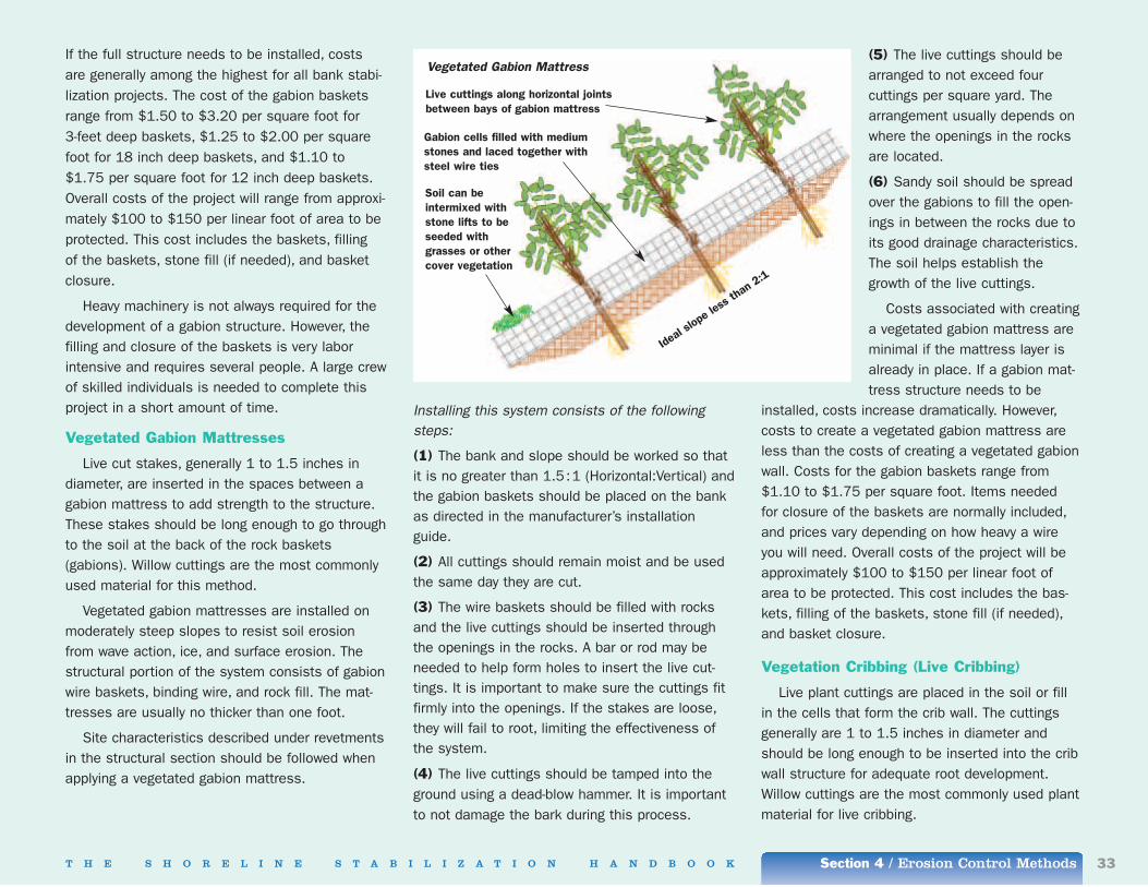
T H E S H O R E L I N E S T A B I L I Z A T I O N H A N D B O O K Section 4 / Erosion Control Methods 33
If the full structure needs to be installed, costsare generally among the highest for all bank stabi-lization projects. The cost of the gabion basketsrange from $1.50 to $3.20 per square foot for 3-feet deep baskets, $1.25 to $2.00 per squarefoot for 18 inch deep baskets, and $1.10 to$1.75 per square foot for 12 inch deep baskets.Overall costs of the project will range from approxi-mately $100 to $150 per linear foot of area to beprotected. This cost includes the baskets, filling of the baskets, stone fill (if needed), and basketclosure.
Heavy machinery is not always required for thedevelopment of a gabion structure. However, thefilling and closure of the baskets is very laborintensive and requires several people. A large crewof skilled individuals is needed to complete thisproject in a short amount of time.
Vegetated Gabion Mattresses
Live cut stakes, generally 1 to 1.5 inches indiameter, are inserted in the spaces between agabion mattress to add strength to the structure.These stakes should be long enough to go throughto the soil at the back of the rock baskets(gabions). Willow cuttings are the most commonlyused material for this method.
Vegetated gabion mattresses are installed onmoderately steep slopes to resist soil erosionfrom wave action, ice, and surface erosion. Thestructural portion of the system consists of gabionwire baskets, binding wire, and rock fill. The mat-tresses are usually no thicker than one foot.
Site characteristics described under revetmentsin the structural section should be followed whenapplying a vegetated gabion mattress.
Installing this system consists of the followingsteps:
(1) The bank and slope should be worked so thatit is no greater than 1.5:1 (Horizontal:Vertical) andthe gabion baskets should be placed on the bankas directed in the manufacturer’s installationguide.
(2) All cuttings should remain moist and be usedthe same day they are cut.
(3) The wire baskets should be filled with rocksand the live cuttings should be inserted throughthe openings in the rocks. A bar or rod may beneeded to help form holes to insert the live cut-tings. It is important to make sure the cuttings fitfirmly into the openings. If the stakes are loose,they will fail to root, limiting the effectiveness ofthe system.
(4) The live cuttings should be tamped into theground using a dead-blow hammer. It is importantto not damage the bark during this process.
(5) The live cuttings should bearranged to not exceed four cuttings per square yard. Thearrangement usually depends onwhere the openings in the rocksare located.
(6) Sandy soil should be spreadover the gabions to fill the open-ings in between the rocks due toits good drainage characteristics.The soil helps establish thegrowth of the live cuttings.
Costs associated with creatinga vegetated gabion mattress areminimal if the mattress layer isalready in place. If a gabion mat-tress structure needs to be
installed, costs increase dramatically. However,costs to create a vegetated gabion mattress areless than the costs of creating a vegetated gabionwall. Costs for the gabion baskets range from$1.10 to $1.75 per square foot. Items needed for closure of the baskets are normally included,and prices vary depending on how heavy a wireyou will need. Overall costs of the project will beapproximately $100 to $150 per linear foot ofarea to be protected. This cost includes the bas-kets, filling of the baskets, stone fill (if needed),and basket closure.
Vegetation Cribbing (Live Cribbing)
Live plant cuttings are placed in the soil or fillin the cells that form the crib wall. The cuttingsgenerally are 1 to 1.5 inches in diameter andshould be long enough to be inserted into the cribwall structure for adequate root development.Willow cuttings are the most commonly used plantmaterial for live cribbing.
Vegetated Gabion Mattress
Live cuttings along horizontal jointsbetween bays of gabion mattress
Gabion cells filled with mediumstones and laced together withsteel wire ties
Soil can beintermixed withstone lifts to beseeded withgrasses or othercover vegetation
Ideal
slope
less
than 2
:1
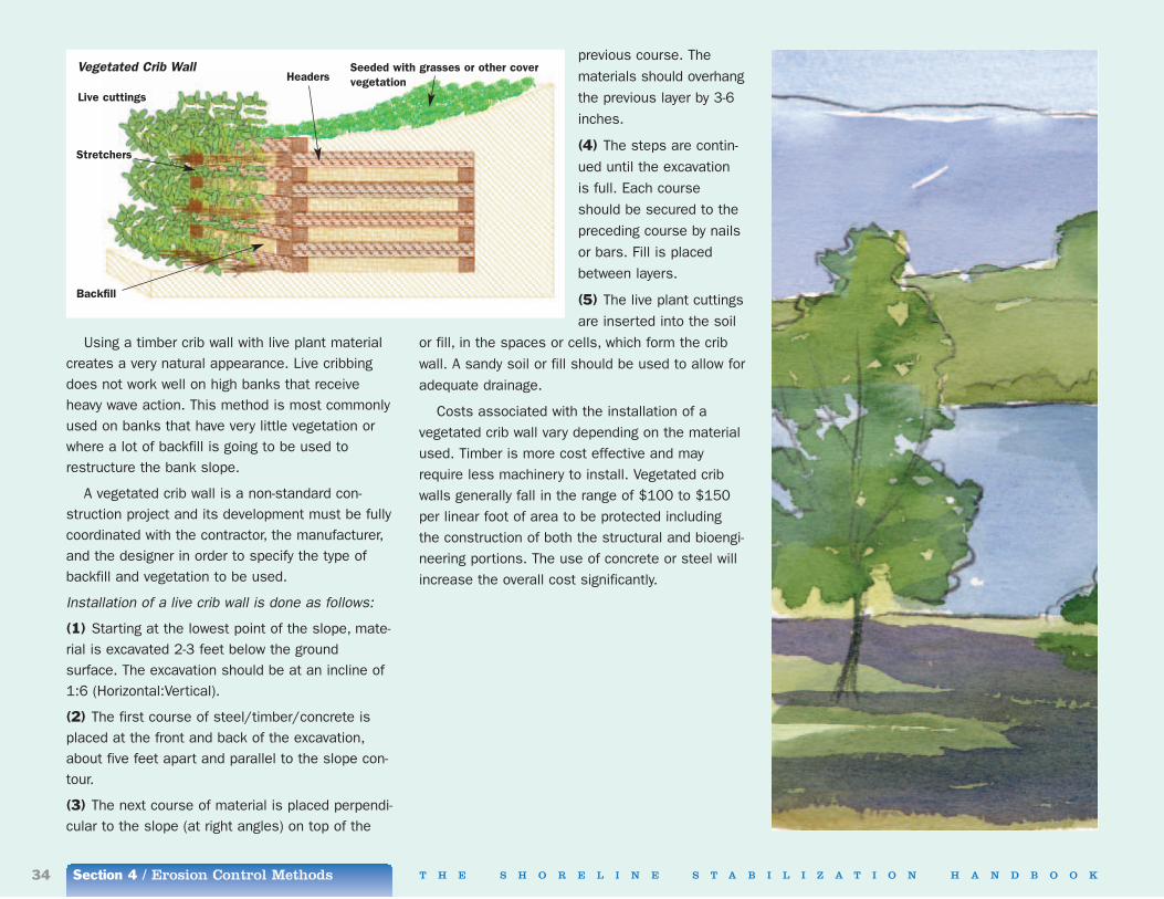
Section 4 / Erosion Control Methods34 T H E S H O R E L I N E S T A B I L I Z A T I O N H A N D B O O K
Using a timber crib wall with live plant materialcreates a very natural appearance. Live cribbingdoes not work well on high banks that receiveheavy wave action. This method is most commonlyused on banks that have very little vegetation orwhere a lot of backfill is going to be used torestructure the bank slope.
A vegetated crib wall is a non-standard con-struction project and its development must be fullycoordinated with the contractor, the manufacturer,and the designer in order to specify the type ofbackfill and vegetation to be used.
Installation of a live crib wall is done as follows:
(1) Starting at the lowest point of the slope, mate-rial is excavated 2-3 feet below the groundsurface. The excavation should be at an incline of1:6 (Horizontal:Vertical).
(2) The first course of steel/timber/concrete isplaced at the front and back of the excavation,about five feet apart and parallel to the slope con-tour.
(3) The next course of material is placed perpendi-cular to the slope (at right angles) on top of the
previous course. Thematerials should overhangthe previous layer by 3-6inches.
(4) The steps are contin-ued until the excavationis full. Each courseshould be secured to thepreceding course by nailsor bars. Fill is placedbetween layers.
(5) The live plant cuttingsare inserted into the soil
or fill, in the spaces or cells, which form the cribwall. A sandy soil or fill should be used to allow foradequate drainage.
Costs associated with the installation of a vegetated crib wall vary depending on the materialused. Timber is more cost effective and mayrequire less machinery to install. Vegetated cribwalls generally fall in the range of $100 to $150per linear foot of area to be protected includingthe construction of both the structural and bioengi-neering portions. The use of concrete or steel willincrease the overall cost significantly.
Vegetated Crib Wall
Live cuttings
Stretchers
Backfill
HeadersSeeded with grasses or other covervegetation

T H E S H O R E L I N E S T A B I L I Z A T I O N H A N D B O O K Section 4 / Erosion Control Methods 35
Guidelines for SuccessThese guidelines are applicable to all methods
and should be completed before installing anystructural, bioengineering, or biotechnical erosioncontrol process. Professional assistance isrequired for proper calculation and design.
Installation
(1) Determine the seasonal range of water levelfor the property. This can be accomplished bymeasuring the high and low water levels each yearor by consulting with local or state officials.
(2) Determine the approximate wave heights towhich the property is subject. Professionals shouldbe contacted to help determine the approximatewave height.
(3) Select a shoreline stabilization technique to beused. Determining what method is best for a par-ticular property is discussed in Section 3 of thehandbook.
(4) Before any work is done, a line of silt fencingneeds to be installed on the down slope side of the shoreline stabilization to prevent water pollution from sediment laden runoff during con-struction. This is important because if this isignored you might be subject to a state or countyfine. The fencing should ideally be installed atleast 6 inches from the water edge. If the fencingneeds to be placed in the water, due to site con-straints, a row of sand bags should be placed onthe inner or outer base of the fencing to hold itdown.
(5) Select a material (plant) to be used for thearmor layer which is capable of resisting the calcu-lated design wave height. (see page 30)
(6) Select the size of material to be used. (seepage 30)
(7) Determine the proper height at which to setthe top of the bank. (see page 11)
(8) Determine if any overtopping is expected forlow structures, if so, implement changes to thedesign to accommodate for overtopping.
(9) Design features if necessary.
(10) Design adequate surface runoff and overtop-ping runoff management structures and provideany other drainage structures that may be neces-sary, such as culverts and ditches.
(11) Consider the ends of the structure to preventflanking and damage to neighboring properties.
(12) Design the toe protection.
(13) Design the filter and underlayers.
(14) Construct the project and,
(15) Provide firm compaction of any fill and back-fill materials.
Monitoring and Maintenance
Once an erosion stabilization project is com-plete, monitoring and maintenance are essentialfor continuing success. Monitoring and maintaininga shoreline stabilization project identifies the needfor repair in a timely manner, provides a basis fordesigning a repair if needed, and provides informa-tion on the performance of the stabilizationinstallation.
Monitoring
Monitoring should be performed on adjacentshorelines up and down from the constructed area to identify any possible neighboring impacts.A simple site inspection performed by someonewith knowledge of the original design of the projectis the most cost effective, and is generally consid-
ered sufficient monitoring. This inspection shouldinclude observing the shore, water, structure,vegetation, and overall environmental conditions.Taking pictures along with notes is the best way to document any problems observed. Periodic pictures of the same area will make it easier toidentify changing characteristics.
Monitoring is of greatest importance during the first two years after construction. Inspectionsshould be conducted after high-water events orheavy storm action. During periods of low-waterlevels, visual monitoring should occur on portionsof the structure under water the majority of theyear.
The type of shoreline erosion protectioninstalled dictates monitoring frequency. As a gen-eral guideline, projects should be monitored atleast twice per year. Projects using bioengineeringmethods are most vulnerable during the firstmonths following installation and should bechecked frequently to identify potential failuresquickly. Special attention should be paid to the toeprotection and the upper bank slope where thenatural bank material or vegetation occurs.Changes in overall conditions of the lake, such aswater level and wave action, should be noted. Anevaluation of vegetative growth and any material

Section 4 / Erosion Control Methods36 T H E S H O R E L I N E S T A B I L I Z A T I O N H A N D B O O K
that has been washed ashore should be part ofevery inspection. Additional planting may beneeded depending on the growth of the plantswithin the first two years.
The project design engineers should stipulatethe monitoring frequency for hard structural projects.For erosion control installations such as construc-ted walls, a professional may need to inspect thestructure.
Maintenance
When maintenance is required, there are twoapproaches: repair the structure at the first sign ofdamage, or take no action until major maintenanceis required. Repairing minimal damage may notalways be cost effective or necessary, particularlywith hard structure solutions. Most projects do nothave to be flawless and will still provide adequateshoreline protection while having minor damage.Knowing whether damage is severe may notalways be obvious and if there is doubt you should
consult a professional. Bioengineering projects dorequire repair as soon as damage is identified ifthe project is in the first two years of develop-ment. After two years, the vegetative roots havetaken hold and repair may not be necessary.Waiting until major maintenance is required is, inmany cases, the best solution.
Repairing a Failed Project
Failure in a project or installation may notalways be easy to identify. The highest failure rateoccurs during the first two years after installationof an erosion control project. Bioengineering projects have a higher failure rate in the first twoyears because the vegetation needs time todevelop. Negative impacts to adjacent propertiescaused by the installation of an erosion controlproject is called flanking and considered a failurethat needs to be addressed accordingly. Slumping,gullying, or bank undermining are signs that thestructure is failing and should be repaired immedi-
ately through re-vegetation or structural repair.Movement of the structure toward the lake or dis-placement of a wall generally means the toe of thestructure is failing and should be repaired byadding additional toe protection or back fillingwhere necessary.
Erosion occurring behind a structure means itwas not built high enough and should be repairedby back filling or increasing the height of the struc-ture. In an installation using large stones androcks, movement of the stones and exposure ofthe filter layer is a common sign of failure and canbe repaired by placing additional stones on top. Aswith planning and designing a shoreline stabiliza-tion project, it is important to consult withprofessionals when a failure and needed repairshave been identified. Repairs need to be carefullythought out and properly installed to prevent fur-ther damage.
T H E S H O R E L I N E S T A B I L I Z A T I O N H A N D B O O K Section 5 / Permit Requirements 37
Permit RequirementsHow to Make the PermitProcess Work for You
As part of the process to create a plan to manage shoreline erosion on your property,
you should determine whether the method(s) andstructure(s) you will use require a permit.Depending on what type of structure is beinginstalled and where, it is possible that permitsmay be required from local, state, and federal gov-ernment agencies. If permits are required, it isvery helpful to contact these agencies early in yourplanning. This enhances full understanding of thepermit requirements and the review processinvolved, giving you the opportunity to include therequirements in the overall design of your installa-tion and avoid costly adjustments after the fact.
The permit process works differently dependingon the type of permit requested. The most impor-tant step is to contact the permitting agency todiscuss the project and complete their applicationforms. It will save you time to have contacted allthe agencies that will be involved in issuingrequired permits. In most instances, a review ofyour application cannot proceed until all the agen-cies that need to be involved have received yourapplication.
Often agency staff will conduct a site visit toobserve the area. When an application is received,the permitting agency will typically publish a publicnotice of the proposed improvements. After thepublic notice is released, a review is held for pub-lic comments regarding the permit application.Waiting periods vary depending on what agency isissuing the permit. Generally once the commentperiod is over and all environmental concerns havebeen addressed, a permit can be issued.
Types of Permits and Permit Authority
Municipal/County Regulations
There is no specific permit information standardused by every level of government. Some permitsare specific to shoreline modifications; othersrequire approvals for aspects of construction typi-cally related to shoreline stabilization (such asfilling, clear-cutting, and land alteration); and oth-ers do not have any permitting or notificationrequirements. You should contact your municipal orcounty office to determine what permitting require-ments apply to your project. Often towns andcounties will refer you to federal agencies such asthe Army Corps of Engineers for permitting. Youshould notify the county and/or any municipalitiesof any shoreline alteration you are planning to do,before starting the work, to identify any regulationswith which you need to comply. A listing of countycontact information and other resources is locatedin Section 6 of this handbook.
Vermont State Permits
In Vermont, permits are required when erosioncontrol installations involve construction, filling, orpotential hazards that alter the shoreline and/orwetlands. The shoreline is considered the sur-rounding perimeters of the Lake Champlain Basinand includes canals and slips. Vermont state per-mitting may also be required for shoreline work ontributaries of the lake. Any project that may alterthe area beyond the mean water level of the lake(95.5 feet) will require a Shoreland EncroachmentPermit. Encroachments include, but are not limitedto, shoreline stabilization projects such as retain-ing walls and revetments. If the lake’s adjacentwetlands are being affected by the project, aWetland Conditional Use Determination from the
Vermont Water Quality Division is required. Alsosome projects on lakes or within the buffer zonealong the shoreline will require an Act 250 permit.
The first step in the Vermont state permittingprocess is to contact the regional permit specialistat your regional Agency of Natural Resourcesoffice. In Grand Isle, Franklin, Chittenden, andAddison Counties, the appropriate regional officeis in Essex Junction, Vermont. The regional officein Rutland should be contacted if one is in RutlandCounty. The permit specialist will provide a projectreview sheet that identifies what permits are likelyrequired with appropriate contact numbers. Thepermit specialist can also provide many permitapplication forms.
When you file your completed application, sendit back with the design plans for your project. Theapplication will be reviewed for compliance with allregulations and you may be asked for additionalinformation. A public notice is typically sent outabout your proposed project to give town officials,neighbors, and any interested persons the oppor-tunity to comment on or object to your project. Inmost instances, your application is approved ordenied within 30-60 days depending on the regula-tory agency. Contact information about Vermontstate government permit agencies is located inSection 6 of this handbook.
New York State Permits
New York State requires permits for any con-struction, excavation, filling, or discharging of fillmaterial into Lake Champlain or onto its banks.The New York State Department of EnvironmentalConservation (NYSDEC) and the Adirondack ParkAgency (APA) are the two permitting agenciesinvolved in shoreline stabilization and erosion con-trol installations.

Section 5 / Permit Requirements38 T H E S H O R E L I N E S T A B I L I Z A T I O N H A N D B O O K
The first step is to contact the NYSDEC and theAPA to discuss your project and obtain a permitapplication form. When you file your completedapplication, send it back with the design plans foryour project. The application will be reviewed forcompliance with all regulations, and you may beasked for additional information. A public notice istypically sent out about your proposed project togive town officials, neighbors, and any interestedpersons the opportunity to comment on or objectto your project. In most instances your applicationis approved or denied within 30-60 days depend-ing on the regulatory agency. Contact informationabout the NYSDEC and APA is located in Section 6of this handbook.
Federal Permits
Any construction, excavation, or discharging offill material that encroaches beyond the ordinaryhigh water mark of Lake Champlain or the lake’sadjacent wetlands and tributaries requires a permit issued by the Army Corps of Engineers.Federal permits are only issued after a state permit has been approved.
You should obtain a permit application from thedistrict offices of the Army Corps of Engineersresponsible for the territory where your shorelineerosion control project will be installed. Once yourcompleted application with design plans isreceived, a public notice will be issued to notifyinterested people of your proposal. If no objec-tions are received within 30 days, the districtengineer will consider issuing a permit based onthe project’s environmental impacts. Contact infor-mation for the Vermont and New York districtoffices of the Army Corps of Engineers is locatedin Section 6 of this handbook.

T H E S H O R E L I N E S T A B I L I Z A T I O N H A N D B O O K Section 6 / Resources and References 39
Resources and ReferencesResources Used in the Development of this Handbook
T hese resources can provide additional guid-ance or assistance in the technical areas
covered in Sections 4 and 5. The list has beensegmented for easier use.
Sources of Information Pertaining to Methods of Erosion Control
A Bioengineering Solution System to CoastalShoreline Stabilization. December 2000. GeorgeFarek and John Lloyd-Reilley. Also go towww.landandwater.com.
Bioengineering for Hillslope, Streambank andLakeshore Erosion Control. November 1996.Thomas G. Franti. Also go towww.ianr.pubs.unl.edu/Soil/g1307.htm.
Biotechnical and Soil Bioengineering SlopeStabilization, A Practical Guide for Erosion Control.1996. Donald H. Gray and Robbin B. Sotir. JohnWiley & Sons, Inc., New York.
Biotechnical Slope Protection and Erosion Control.1982. Donald H. Gray and Andrew T. Leiser. VanNostrand Reinhold Company, New York, New York.
Brush Mattresses for Streambank Erosion Control.May 2001. Hollis H. Allen and Craig Fischencih.
Control of Soil Erosion. January 1996. Robert P.Stone and Neil Moore. Ontario Ministry ofAgriculture and Food, Ontario, Canada. Also go towww.gov.on.ca.
Design Recommendations for Riparian Corridorsand Vegetated Buffer Strips. April 2000. RichardA. Fischer and J. Craig Fischenich.
Gabions for Streambank Erosion Control. May2000. Gary E. Freeman and J. Craig Fischenich.
Ice Push Damage on Lake Bomoseen, Vermont.Final Report. May 2001. U.S. Army Corps ofEngineers, State of Vermont, and Lawrence W.Gatto, Michael G. Ferrick, and Darryl J. Calkins.Impacts for Stabilization Measures. May 2001.Craig Fischenich.
Lake Champlain Shoreline Erosion Control. NewEngland River Basins Commission and Army Corpsof Engineers.
Live and Inert Fascine Streambank ErosionControl. May 2001. Robbin B. Sotir and CraigFischenich.
Shoreline Erosion and Its Potential Control onThurmond Lake. Erosion Control Magazine.December 1999. Bruce K. Ferguson. Also go towww.forester.net/ec_9911_shoreline.html.
Shoreline Stabilization Using Wetland Plants andBioengineering. Volume 46, Number 3. June 2002.Cathy J. Wendt and Hollis H. Allen. WisconsinValley Improvement Co., Wausau, Wisconsin.
Soil Bioengineering Measures for Hill and SlopeStabilization Works With Plants. Florin Florinethand Cristopher Gerstgraser, Institute of SoilBioengineering and Landscape Construction,University of Agriculture, Forestry and RenewableNatural Resources, Vienna, Austria.
Soil Bioengineering. Rick Grillmayer, NottawasagaValley Conservation Authority. Also go tohttp://collections.ic.gc.ca/streams/tech/S-engineering.html.
Streambank Stabilized Using NaturalBioengineering Solutions. November 2000. MurrayMcHugh. Also go to www.landandwater.com.
The WES Stream Investigation and StreambankStabilization Handbook. David S. Biedenharn,Charles M. Elliott, and Chester C. Watson. October1997.
Use of Riprap in Soil Bioengineering StreambankProtection. Robbin B. Sotir and Nelson R.Nunnally. Robbin B. Sotir & Associates Inc.,Marietta, Georgia. Also go towww.sotir.com/pubs/publist/riprap/riprap.html.
Sources of Information Pertaining to Plants
Controlling Erosion Using Vegetation. AccessWashington. Department of Ecology. Also go towww.ecy.wa.gov.
Buffer Strips for Riparian Zone Management.January 1991. U.S. Army Corps of Engineers, NewEngland Division, Waltham, Massachusetts.
Manual of Vascular Plants of Northeastern UnitedStates and Adjacent Canada. 1991. HenryGleason and Arthur Cronquist. The New YorkBotanical Garden, Bronx, New York.
Native Shrubs for Landscaping. 1987. Sally L.Taylor, Glenn D. Dreyer, William A. Niering. TheConnecticut Arboretum at Connecticut College,New London, Connecticut. 40 pp.
Native Vegetation for Lakeshores, Streamsidesand Wetland Buffers: What you need to know tore-establish or enhance a buffer strip along waterand wetland in Vermont. 1994. VermontDepartment of Environmental Conservation, WaterQuality Division, Waterbury, Vermont. 52 pp.
Sources of Native Plant Materials in Vermont.August 2003. Vermont Department ofEnvironmental Conservation, Water QualityDivision, Waterbury, Vermont. 19 pp.
Plant Material Selection and Acquisition. May2001. Craig Fischenich.

Section 6 / Resources and References40 T H E S H O R E L I N E S T A B I L I Z A T I O N H A N D B O O K
Recommended Trees for Vermont Communities,2001. Vermont Department of Forests, Parks, andRecreation. Also go to www.vtcommunityforestry.orgfor additional publications and information.
Tree pamphlets: Benefits of Trees, Tree Selection,New Tree Planting, Mature Tree Care. 1991.International Society of Arboriculture. 4 pp ea.Available from the Vermont Department of Forests,Parks, and Recreation.
Wetland, Woodland, Wildland: A Guide to theNatural Communities of Vermont, 2000. ElizabethThomson and Eric Sorenson. Published by theVermont Department of Fish and Wildlife and TheNature Conservancy.
FEMA: National Flood Insurance Program. Go towww.fema.gov/.
Who Provides Assistance
These are the phone numbers and contactinformation for regional, state and federal officialsin the Lake Champlain Basin. All of the sourceslisted can provide assistance and some may bemore knowledgeable about the areas covered inthe handbook. All published numbers are as ofApril 2004.
Vermont and New York Cities and Towns
Starting a conversation on shoreline stabilizationwith your local municipal officials can be highlybeneficial. Vermont and New York Cities and Towns can provide assistance and directionregarding permitting, town regulations, shorelineconstruction, and questions about Lake Champlainand the other bodies of water in their areas ofjurisdiction. They may also be able to recommendadditional sources of information.
County-Based Planning Organizations
Vermont Regional Planning Commissions and New York County Planning Offices can provideassistance in planning programs related to LakeChamplain, grants and funding, acquiring local andregional maps, and responding to questions aboutlocal, state, and federal regulations. New YorkPlanning Offices can provide assistance anddirection regarding county regulations andpermitting of shoreline construction projects.
Vermont Regional Planning Commissions
Addison County Regional Planning Commission(802) 388-3141, www.acrpc.org.
Chittenden County Regional Planning Commission(802) 846-4490, www.ccrpcvt.org.
Northwest Regional Planning Commission(802) 524-5958, www.nrpcvt.com.
Rutland Regional Planning Commission(802) 775-0871, www.rutlandrpc.org.
New York County Planning Offices
Clinton County Planning Office(518) 565-4711 or (518) 565-4709
Essex County Planning Office (518) 873-3685
Washington County Planning Office (518) 746-2290
Vermont Agency of Natural ResourcesRegional Offices
Vermont Agency of Natural Resources regionaloffices can provide assistance in permitting,regulations, shoreline construction projects, andother areas relating to natural resources inVermont.
Franklin, Chittenden, Grand Isle, and AddisonCounties
Agency of Natural Resources Office (802) 879-5656
Act 250 Information (802) 879-5614
Contacts• Permit Specialist• Chittenden County Coordinator• Franklin, Grand Isle and
Addison County Coordinator• Regional Engineer• Assistant Regional Engineers
Address111 West St.Essex Junction, Vermont 05452
Rutland County
Permit Specialist (802) 786-5907
Agency of Natural Resources Office (802) 786-5920
Act 250 Information (802) 786-5920
Contacts• Rutland County Coordinator• Regional Engineer• Assistant Regional Engineers
AddressAsa Bloomer State Office BuildingRutland, Vermont 05701-5903

T H E S H O R E L I N E S T A B I L I Z A T I O N H A N D B O O K Section 6 / Resources and References 41
Vermont Department of EnvironmentalConservation, Water Quality Division
The Department of Environmental Conservation(Water Quality Division) can provide assistance inlake watershed and shoreland management, plantidentification, and native and exotic aquatic plantspecies. The Department also provides assistancethrough its wetlands, rivers, dams, and stormwaterprograms.
www.vtwaterquality.org.
Lakes & Ponds Management /Protection Section(802) 241-3777
Wetlands Section(802) 241-3754
Chittenden CountyDistrict Wetlands Ecologist, (802) 241-1418
Addison & Rutland CountiesDistrict Wetlands Ecologist, (802) 241-3761
New York State Department ofEnvironmental Conservation and Adirondack Park Agency
The New York State Department of EnvironmentalConservation and the Adirondack Park Agency canprovide assistance in lake watershed managementand land use management, plant identification,native and rare aquatic plant species, wildlifehabitat, permitting, wetland evaluation andprotection, and about the laws and regulations inNew York State. The Adirondack Park Agency hasauthority only within the Adirondack Park.
Division of Environmental Permits, Region 5Raybrook Office
ContactsRegional Permit Administrator, (518) 897-1234Deputy Regional Permit Administrator, (518) 897-1234
AddressNYS Dept. of Environmental ConservationRoute 86P.O. Box 296, Raybrook, NY 12885-0296
Division of Environmental Permits, Region 5Warrensburg Office
ContactDeputy Regional Permit Administrator, (518) 623-1281
AddressNYS Dept. of Environmental ConservationCounty Route 40P.O. Box 220, Warrensburg, NY 12885-0220
Adirondack Park Agency
ContactDivision of Regulatory Programs,(518) 891-4050
www.northnet.org/adirondackparkagency
AddressDivision of Regulatory ProgramsP.O. Box 99Ray Brook, New York 12977
U.S. Army Corps of Engineers
The U.S. Army Corps of Engineers issues permitsand can answer technical questions regardingshoreline construction projects.
Vermont Project Office
ContactSenior Project Manager, (802) 872-2893Project Manager, (802) 872-2893
AddressVermont Project OfficeU.S. Army Corps of Engineers8 Carmichael Street, Suite 205Essex Junction, VT 05452
New York District Office
Contact (212) 264-0185www.nan.usace.army.mil
AddressU.S. Army Corps of EngineersAttn: Regulatory Branch—Room 193726 Federal PlazaNew York, NY 10278-0090

Section 6 / Resources and References42 T H E S H O R E L I N E S T A B I L I Z A T I O N H A N D B O O K
Soil and Water Conservation Districts
The Soil and Water Conservation Districts provideassistance on issues relating to erosion control,water quality, wildlife habitat, and land usemanagement.
Clinton County
Office (518) 561-4616 ext. 3
Contacts• District Manager• District Conservationist• Soil Conservation Technician
Address6064 Route 22, Suite 1Plattsburgh, New York 12901
Essex County
Office (518) 962-8225
Contacts• District Field Manager• District Office Manager• Lake Champlain Water Quality Specialist
AddressCornell Cooperative Extension CenterP.O. Box 407Westport, New York 12993
Washington County
Office (518) 692-9940 ext. 3
Contacts• District Manager• Office Manager• District Technician
AddressUSDA Service Center2530 State Route 40Greenwich, New York 12834-9627
Natural Resources Conservation Service
The Natural Resources Conservation Serviceprovides assistance on issues relating to erosioncontrol, water quality, and land use management.They also may provide assistance relating toproject funding.
Vermont Service Centers
St. Albans (802) 527-129627 Fisher Road
Williston (802) 879-4785600 Blair Park Rd., Suite 280
Berlin (802) 828-4493617 Comstock Rd, Suite 1
Middlebury (802) 388-674868 Catamount Park
White River Jct. (802) 295-794228 Farm View Dr.
Rutland (802) 775-8034170 S. Main St.
Vermont Natural ResourcesConservation Districts
The Vermont Natural Resources ConservationDistricts provide assistance in wetlandconservation and restoration, wildlife habitat,aquatic habitat, land management, and otherareas related to land conservation.
Franklin County NRCD (802) 524-6505
Grand Isle NRCD (802) 864-0223
Rutland NRCD (802) 775-7192
Winooski NRCD (802) 872-2861
Flood Insurance
FEMAwww.fema.gov1-877-FEMA-MAP
Flood Insurance Agencywww.floodinsuranceagency.com
T H E S H O R E L I N E S T A B I L I Z A T I O N H A N D B O O K Section 6 / Resources and References 43
Section 7 / Glossary44 T H E S H O R E L I N E S T A B I L I Z A T I O N H A N D B O O K
GlossaryArmor: The outer layer of material, usually heavystone, of a control structure exposed to directwave action.
Bank: The rising ground bordering the sea, river,or lake.
Beach: The zone of unconsolidated material thatextends landward from the low water line to theplace where there is marked change in material or physiographic form, or the line of permanentvegetation.
Bedrock: A general term for the rock, usuallysolid, that underlies soil or other unconsolidated,surface material.
Bioengineering: The use of live plants and plantmaterial to reinforce soil, serve as water drains,act as erosion prevention barriers, and promotewater drainage in wet soils.
Biotechnical: The use of both live plant materialand inert structures to stabilize and reinforceslopes.
Bluff: An unvegetated high bank composed largelyof unconsolidated deposits with a near-verticalface overlooking a body of water.
Bluff Crest: Upper edge or margin of a shorelinebluff.
Bluff Face: The sloping portion of a high bank.
Bluff Toe: The base of a bluff where it meets thebeach.
Riparian Buffer: A protective strip of vegetatedland.
Clear-cut: A timber harvest method that removesall the trees on an area in one operation.
Cliff: A high, very steep to perpendicular or over-hanging face of rock rising above the shore.
Downdrift: The direction of predominant move-ment of coastal materials by currents.
Drainage (soil): The rapidity and extent of theremoval of water from the soil by surface runoffand by down-draw flow through the soil.
Erosion: The wearing away of rock or soil and theresulting movement of particles by wind, water, ice,or gravity.
Fetch: A continuous length of water over whichwinds blow in one direction.
Flow: A mass movement involving rapid flowage ofwet soil, rock, and displaced vegetation as a vis-cous mass down a slope or a channel; includingmudflow, debris flow, and earth flow.
Geomorphology: The study of the characteristics,origin, and development of landforms.
Gully: Large intermittent drainage channel devel-oped from the erosion forces of drainagesoccurring from surface water runoff.
Impermeable: Having a texture that does not permit fluids to move through it freely.
Infiltration: The movement of water or solutionsinto or through a rock or soil through its cracks orfractures; the flow of rainwater into soil material.
Joint: A crack formed in rock by movements nor-mal to the cracks and without shear movements ofthe rock on either side of the crack.
Mass Movement: Movement of a portion of landsurface down a slope as a slide, a flow, or soilcreep in which gravity is the main driving force.
Natural Landscape Elements: The natural water-courses, topography, hydrology, and vegetation thatcomprise a particular site.
Percent Slope: The direct ratio (multiplied by100) between the vertical and the horizontal dis-tance for a given slope; e.g., a 3-foot rise in a10-foot horizontal distance would be a 30 percentslope.
Rill: A tiny drainage channel cut in a slope by theflow of water. Can develop into a gully with continu-ing erosion.
Runoff: That part of the precipitation that appearsin uncontrolled surface streams, drains, or sewers.It is stream flow unaffected by artificial diversion,imports, storage, or other works in or on thestream channels.
Saturated: A condition in which the joints of amaterial are filled with a liquid, usually water.
Shoreline: The intersection of a specified planeor water with the beach. It migrates with changesof the water level.
Slide: A mass movement resulting from failure ofsoil or rock along a rotational or planar surface.
Slope: The inclination of the land surface from thehorizontal percentage of slope. It is the verticaldistance divided by the horizontal distance andmultiplied by 100.
Moderate Slope: Considered to be a slope thatis 45 degrees (1:1) or less.Steep Slope: Considered to be a slope that isgreater than 45 degrees.
Slump: A slide characterized by a rotary move-ment of a generally independent mass of rock orearth along a curved slip surface.
Soil: The loose surface material capable of sup-porting plant growth, and having propertiesresulting from the integrated effect of climate andliving matter on the decomposition of bedrock andsurficial surface deposits.
T H E S H O R E L I N E S T A B I L I Z A T I O N H A N D B O O K Section 7 / Glossary 45
Soil Creep: The gradual and steady downhillmovement of soil and loose rock material on aslope.
Till: Poorly sorted and generally unstratified sedi-ments, deposited directly by and underneath aglacier.
Toe of Slope: A break in the slope at the foot ofa bank.
Unconsolidated: Sediment where particles areloose and not cemented together.
Upland: A general term for elevated land abovethe beach that lies above the extreme high waterlevel.
Wetlands: Lands where the water table is near orat the surface most of the year. Aquatic vegeta-tion, such as cattails, is typical. Lands such asmarshes and swamps are typical wetlands.

Section 8 / Index46 T H E S H O R E L I N E S T A B I L I Z A T I O N H A N D B O O K
IndexNote: Italicized page locators refer to figures/tables.
AAct 250 permit, 37
Addison County, Vermont Department of NaturalResources regional offices for, 40
Adirondack Mountains, 2
Adirondack Park Agency, 37, 38, 41
Aesthetics, bioengineering and, 26
Agriculture, soil erosion and, 6
Alder
brush layering with, 28
live staking with, 26
APA. See Adirondack Park Agency
Aquatic forces, erosion caused by, 5 - 6
Armor, 44
Armor layer, within revetment, 21
Army Corps of Engineers. See U.S. Army Corps of Engineers
BBackfill, 11, 24
Bank, 44
Bank erosion, revetments and, 21
Beaches, 6, 10, 44
Bedrock, 44
Berms, 20
Bioengineering, 8, 44
brush layering, 28 - 29
brush matting, 29 - 30
contour wattling, 27-28
erosion stabilization, 13, 16, 17, 26 - 30
live staking, 26 - 27
plant harvesting, 30
plant selection, 30
Biotechnical, 44
erosion stabilization, 13, 16, 17, 31 - 34
Biotechnical shoreline stabilization
erosion control matting, 31 - 32
vegetated gabion mattresses, 33
vegetated gabion walls, 32 - 33
vegetation cribbing, 33 - 34
Bluff, 44
Bluff crest, 44
Bluff face, 44
Bluff toe, 44
Boat traffic, wave action and, 5
Boulders, removing, 11
Breakwaters, 25
Brush layering, 28 - 29
Brush matting, 26, 29 - 30
Brush mattresses, 29
Bulkheads, common types of, 24 - 25
CChamplain Canal, 2
China, bioengineering in, 26
Chittenden County, Vermont Agency of NaturalResources regional offices for, 40
Clear-cutting, 6, 44
Cliff, 44
Concrete seawalls, 23 - 24
Consolidated shoreline materials, 4
Contour wattling, 27 - 28
Costs
bio-engineering stabilization, 16
bio-technical stabilization, 16
breakwaters, 25
brush layering, 29
bulkheads, 25
concrete seawalls, 23 - 24
construction, 11
contour wattling, 28
erosion control matting, 31
gabion mattress, 22
live staking, 27
non-structural stabilization, 14
stone riprap, 22
structural stabilization, 14
vegetated crib walls, 34
vegetated gabion mattresses, 33
vegetated gabion walls, 32 - 33
vegetated riprap, 32
County soil surveys, 8
Cribbing, 24 - 25, 33
Crib walls, constructing, 24 - 25
DDamage, repairing, 36
Dead blow hammers, live staking with, 26, 27
Design, land use, 18
Developers, awareness by, 18
Dogwood
brush layering with, 28
brush matting with, 29
live staking with, 26
Dormancy, plant harvesting during, 30
Downdrift, 44
Drainage, 44
improving, 20
observing patterns with, 8
EEconomic development, and Lake Champlain Basin, 2
Education, about shoreline erosion, 18
Encroachments, 37
Environmental management, 18
Erosion, 44
aquatic forces, 5 - 6

T H E S H O R E L I N E S T A B I L I Z A T I O N H A N D B O O K Section 8 / Index 47
causes of, 4 - 6
human activities, 6
as natural process, 18
terrestrial forces, 4
Erosion control, sources of information on, 39
Erosion control installation
drafting plan, 10 - 11
planning, 8, 10 - 11
Erosion control matting, 31 - 32
Erosion control methods
bioengineering, 13, 16, 17, 26 - 30
biotechnical, 13, 16, 17, 31 - 34
guidelines for success, 35-36
non-structural and preventive, 13, 14, 15, 18 - 20
structural, 13, 14, 15, 21 - 25
Erosion stabilization projects
maintaining, 36
monitoring, 35 - 36
repairing failed projects, 36
Europe, bioengineering in, 26
FFailed projects, repairing, 36
Fascines, 27
Federal Emergency Management Agency, 11, 42
Federal permits, 38
FEMA. See Federal Emergency Management Agency
Fencing, 35
Ferns, from regional nurseries, 19
Fetch, 44
Filter fabric, for stone riprap revetment, 21, 22
Filter layer, within revetment, 21
Fish habitat, bioengineering and, 26
Flood insurance, 42
Flood insurance maps, 11
Flood line, on Lake Champlain, 11
Floodplains, 11
Flow, 44
Forests, clear-cutting of, 6, 44
Franklin County, Vermont Agency of Natural Resourcesregional offices for, 40
Frost action, 4
Funding. See Costs
GGabion mattress, 22
vegetated, 33
Gabions, 22, 23, 32
Gabion walls
installing, 23 - 24
vegetated, 32 - 33
Geofabrics, 28
Geogrids, 28
Geomorphology, 44
Government funding, for construction costs, 11
Grading and shaping slopes, guidelines for, 11
Grand Isle County, Vermont Agency of Natural Resourcesregional offices for, 40
Grasses, 19
for slope face plantings, 20
for slope stabilization, 30
Green Mountains, 2
Groins, 25
Ground covers, 19
Groundwater, 4
Gullies/Gullying, 5, 20, 44
HHerbaceous plants
from regional nurseries, 19
for slope stabilization, 30
Houses, 10
Hudson River, 2
Human activities, and shoreline erosion, 6
IIce push, 6
Impermeable, 44
Infiltration, 44
Insurance
flood, 42
property, 11
Interceptor drains, 20
Intervale Foundation, 19
JJoint, 44
Joint planting, 31 - 32
LLake Champlain
concrete seawalls along, 22
flood line on, 11
general characteristics of, 2
revetment types on, 21 - 22
Lake Champlain Basin
local, state, and federal officials in, 40 - 41
non-native species in, 20
topographic map of, 2
Vermont state permits and, 37
Lake shorelines, erosion and, 4
Lakeshore property, insuring, 11
Land preparation
description of, 10 - 11
permitting process and, 10
Landslides, 4
Land use planning, 18
Live crib walls, installing, 34
Live fascine bundling, 26
brush matting and, 29
installing, 27 - 28
Live staking, 26 - 27

Section 8 / Index48 T H E S H O R E L I N E S T A B I L I Z A T I O N H A N D B O O K
Local government, awareness by, 18
Longshore drift, 5, 6
Low water season
bioengineering controls installed during, 26
bulkhead installation during, 24
MMaintenance, of erosion stabilization projects, 36
Maps, flood insurance, 11
Mass movement, 44
Matting, 29
Moderate slope, 44
Monitoring, erosion stabilization projects, 35
Municipal/county regulations, 37
NNational Flood Insurance Program, 11
Native plants, from regional nurseries, 19
Native species
live staking with, 26
re-vegetation with, 19 - 20
Natural landscape elements, 44
Natural Resources Conservation Service, 8, 42
Natural shoreline processes, 5
Natural vegetation, 10
Neighbors, shoreline stabilization and, 10
New York, flood insurance maps for, 11
New York County Planning Offices, 40
New York State Department of EnvironmentalConservation, 37, 38, 41
New York State permits, 37 - 38
Non-native species
avoiding, 30
in Lake Champlain Basin, 20
Non-structural/preventive erosion stabilization, 13, 14,15, 18 - 20
NRCS. See Natural Resources Conservation Service
Nurseries
native plants from, 19
as resources, 30
NYSDEC. See New York State Department ofEnvironmental Conservation
OOrdinances, 18
PPercent slope, 44
Permit process
making it work, 37
shoreline stabilization and, 10
Permits, types of, 37 - 38
Permitting agency, 37
Piles, 24
“Pioneer species,” for slope face plantings, 20
Plants
for bioengineering/biotechnical installations, 26, 30
erosion control and, 13
from regional nurseries, 19
sources of information on, 39 - 40
Population growth, and Lake Champlain Basin, 2
Property insurance, 11
Property owners, awareness by, 18
Property surroundings, identifying, 10
Protractor, for measuring slope angle, 8
Pruning shears, for plant harvesting, 30
Public notices, permitting and, 37, 38
RRaindrop splash, 5
Rainfall, and Lake Champlain Basin, 2
Red osier dogwood, contour wattling with, 27
Regional Agency of Natural Resources, 37
Regional planning commissions, 40 - 41
Relocation, 20
Re-vegetation, with native species, 19 - 20
Revetments, 21 - 22
layers within, 21
types of, on Lake Champlain, 21 - 22
Richelieu River, 2
Rill/Rilling, 5, 44
Riparian buffer, 44
Riprap, for stable toe, 27
Roadways, 10, 20
Runoff, 20, 44
Rutland County, Vermont Agency of Natural Resourcesregional offices for, 40
SSaturated condition, 44
Saws, for plant harvesting, 30
Seawalls, 6, 22
concrete, 23 - 24
Sedges, 19
Septic systems/structures, 10, 20
Sheet erosion, 5
Sheet piles, 24
Shoreland Encroachment Permit, 37
Shoreline, 44
natural processes along, 5
Shoreline buffer zones, 10
Shoreline Checklist, 9
Shoreline erosion
aquatic forces and, 5 - 6
categories of, 4
characterizing, 8
human activities and, 6
terrestrial forces and, 4
Shoreline materials, categories of, 4
Shoreline stabilization, 6
methods for, 13, 14 - 17
re-vegetation and, 19 - 20

T H E S H O R E L I N E S T A B I L I Z A T I O N H A N D B O O K Section 8 / Index 49
Shrubs
from regional nurseries, 19
for slope stabilization, 30
Silt fencing, 35
Site evaluation, 8
Site planning, 10, 18
Slide, 44
Sliding, 4
Slope, 44
Slope angle, measuring, 8
Slope crest, 11
Slope crest planting, 19 - 20
Slope face, 11
Slope face planting, 20
Slope toe, 11
Slope toe planting, 20
Slump/Slumping, 4, 44
Snowberry, contour wattling with, 27
Soil, 44
Soil and Water Conservation District, 41
Soil characteristics, determining, 8
Soil creep, 4, 45
Soil erosion, 6
Steel/timber cribbing, 24 - 25
Steep slope, 44
Stone riprap revetment, 21 - 22
Storms, 6
Stormwater runoff, 6
Structural erosion stabilization, 13, 14, 15, 21 - 25
Stumps, removing, 11
TTerraces, 11
Terrestrial forces, erosion caused by, 4
Till, 45
Toe
in revetment, 21
of slope, 45
Trees
from regional nurseries, 19
for slope face plantings, 20
for slope stabilization, 30
UUnconsolidated sediment, 45
Unconsolidated shoreline materials, 4
United States, bioengineering in, 26
Upland, 45
Urbanization, 6
U.S. Army Corps of Engineers, 37, 38, 41
VVegetated crib wall, 34
Vegetated gabion mattresses, 33
Vegetated gabion walls, 32 - 33
Vegetated riprap (joint planting), 31 - 32
Vegetation
bioengineering with, 13
clearing of, 6
identifying, 8
removal of, 11
use of natural, 10
Vegetation cribbing (live cribbing), 33 - 34
Vermont, flood insurance maps for, 11
Vermont Department of Environmental Conservation,Water Quality Division within, 40
Vermont Agency of Natural Resources,regional offices of, 40
Vermont Natural Resources Conservation Districts, 42
Vermont permits, 37
Vermont Regional Planning Commissions, 40
Vermont Water Quality Division, Wetland Conditional UseDetermination from, 37
Viburnum, brush matting with, 29
Vines
from regional nurseries, 19
for slope stabilization, 30
WWater level, of Lake Champlain, 2
Water lines, 20
Wave action, 5-6
Wetland Conditional Use Determination, 37
Wetlands, 10, 37, 45
Wildlife habitat, bioengineering and, 26
Willow
brush layering with, 28
brush matting with, 29
contour wattling with, 27
live cribbing with, 33
live staking with, 26
vegetated riprap and, 31
Winds, 2, 4
YYardstick, for measuring slope angle, 8
ZZoning, 18. See also Permit process

Northwest Regional Planning Commission
7 Lake Street, Suite 201St. Albans, VT 05478
Tel: (802) 524-5958
Email: [email protected]


