
RIEMER, K.L. The role of computers in the detection and research of seismic events on the West Wits Line. APCOM 87. Proceedings of the Twentieth International Symposium on the Application of Computers and
Mathematics in the Mineral Industries. Volume 1: Mining. Johannesburg, SAIMM, 1987. pp. 55-80.
The Role of Computers in the Detection and Research of Seismic Events on the West Wits Line
K.L. RIEMER
West Driefontein Gold Mine, Carletonville, South Africa
The West Wits Line first began yielding gold in the mid-1930s and is among South Africa's leading gold-producing areas. Gold mining operations are carried out amidst the occurrence of seismic events which cause both damage to underground excavations and injury and loss of life to production personnel. The feasibility of establishing a system to minotor the seismicity on all the Gold Fields mines was investigated during the early 1980s. This led to the establishment of a centralized seismic network in 1981.
The system was structured around three major objectives. It uses Perkin Elmer (now Concurrent Computer Corporation) 16 and 32 bit mini-computers. The hardware in use at both the central and remote sites is outlined, giving a good insight into the role of computers in the system. The system software reveals the fast flow of data through the network; it can be divided into three categories: (1) data logging and transmission - remote sites, (2) data capture and communications - central site, (3) applications and research - central site.
Several examples are given which show how the system is measuring up to its objectives. These case studies also indicate how the computers are effective in representing the seismic data collected. It is concluded that the use of computers enables the pin-pointing of seismic events on the West Wits Line within about 3 - 4 minutes of their oc<:urrence.
The choice of hardware is largely dependent on the objectives of system, and the Gold Fields Network has chosen mini-computers because of the speed of communication and the large amount of data and storage required for
research applications.
Introduction
The economic potential of Carletonville
area was realized with the discovery of
the gold bearing reefs of the Upper
Throughout its 55-year history the area
has been responsible for 15 gold mining
leases. 1 In addition to the high tonnages
Witwatersrand series by Dr Rudolf
Krahmann. This resulted in the
development of the West Wits Line (Figure
1) which was to add a new dimension to
South Africa's gold reserves. Mining
operations in the area star ted i n 1934
with t he Venterspost Gold Mine, and today
the West Wits Line is among t he top
producing regions of the country.
in the area, mi ning operat i ons are
extending to progressively greater depths,
with layouts in the region of 4 DOOm below
surface presently being planned.
One of the problems which has burdened
the gold mining industry since its early
days, and in which the West Wits Line is
no excepti on, is that of rockbursts and/or
seismic events. These dangerous releases
DETECTION AND RESEARCH OF SEISMIC EVENTS ON THE WEST WITS LINE 55
I
r

~ ~ :;:: ~ ~ ~ R ~ :I:
l>
Z
12
DRN
OK
L
/'
hlO
CA
MQ
lOI,I
fj B
LY
8"'$
IIIA
'"
WO
L
~A"
IIII
'"
" ~
I f"".~
ELR
II
UT
OII
VJ.
.L£
CI
.oG
HA
NN
€ K
LF
~ ..
LIB
~~ L
" V
NT
R
EP
UB
UC
O
f S
OU
TH
A
FRIC
A.
AS
l LO
NC
O)!
CA
PE
TO
WN
~T !
LIZ
"'S
ET
K
CR
N
DO
OR
NF
ON
TE
IN
DE
EL
KR
AA
L
BL
YV
QO
R
WES
TER
N
DE
EP
ELA
ND
S RA
ND
KL
OO
F L
lBA
NO
N
VEN
TER
SPO
ST
LE
VE
LS
6 ~ ~
CA
RL
ET
ON
VIL
LE
/'
\ /
L 18
DR
IEF
ON
TE
IN
CO
NS
OL
IDA
TE
D
KLF
WD
L
0 __
' '_
3 4
5 6
7 8
9 10
11
" KM
----
--
--
-SC
AL
E
FIG
UR
E 1
. P
lan
of
loca
tion
of
min
es o
n th
e W
est
Wit
s L
ine
T--
----
---
WE
ST
ER
N
AR
EA
S

of energy s how a ll the properties of
natural earthquakes and range in sca l e
from micro fractur i ng of t he rock to
violent r e l eases of ene rgy measuring 5,2
on the Richter Scale. The events can
disrupt mining operations by causing
frequent damage to underground workings as
well as inj uries and loss of life to
underg round pe rsonnel.
In confyonting
disciplines
seismology
of
have
these problems , the
Rock Mechanics and
received enormous
attention ove r the l as t twenty years. One
of the first t asks i n seismology was the
locat i on of the hypo centers of these
events ; th is need l ed to the estab.lishment
of a number of
individual mines
seismic networks on
from the late 19605
onwa rds . Although s ome of the early
systems us ed ana logue t echni ques. most of
the s ubsequent s ys t ems r esorted to digital
methods and the us e of computers to carry
out sei~mic r es ea rch.
Gold Fie l ds of South Africa has
extensive inte rests i n the Wes t Wits Line,
and it inves tigated the feasibility of
establishing a seismic network during the
late 19705 . The purpose of this paper is
to descri be the applicat i on of computers
and t heir rol e ill the detection and
research of s e ismic events using the Gold
Fields system on the Wes t Wi t s Line. The
development of the s e i s mic
outlined together with
object ives .
The compute r hardware
network is
its major
i n use is
described in some de tai l . and the role of
the compute r s i n t erms of the applications
software is then considered. Some
examples are put forward on how the system
is meeting i ts objectives, and finally
various conclusions on the system and on
the use of computers are outlined.
The Gold Fields Network and system objectives
When the Go l d Fields Network was
establis hed . s everal objectives were laid
down for its operation. These have been
outlined by De Jongh and Klokow.~ For the
purpose of this s tud y , they are summarized
below:
Immediate objectives
It was decided that the system would
function as a management tool, including
the rapid location of seismic events.
This facilit y was vi tal j~ order to
implement rescue operations as soon as
possible whenever the need a rose .
Medium term objectivE's
Once the locations of seismic events had
been obtained they could be stored and
used to identify active geo logical
s tructures s uch as dykes and faults.
This would then assi s t in pl anning of mine
layouts and r emnant blocks. In addition,
it was hop ed t hat the information would
provide feedback on the use of various
support methods such as backfill and
stabilizing pillars .
Long term objectives
Once the patterns and the occurrence of
se1smicity had been observed on the mine,
it was hoped t o be able to study in more
detail the factors causing these events.
This would include detailed seismogram
analys is, stress migrations, laws of
attenuation and in general a more detailed
analYSis of the wave forms.
Motivation for a seismic network within
the Gold Fields Group started in about
1979 on the West Dr iefontei n mine. During
the next two years extensive work was
carried ou t by Or Rod Green (Bernard
Price Institute, University of the
Witwatersrand) and Miles Forsyth (Mining
Stress Systems) on ·the design of the
system and on the selection of suitable
DETECTION AND RESEARCH OF SEISMIC EVENTS ON THE WEST WITS LINE 57
r I I

~
00
1; z ~ '" R
~ ; ~ Q
LOC
AL
MIN
E IN
STA
LLA
TIO
NS
II
N
IIN
n
,aU
IWfN
T ~
,mllP
M'N
T
SHA
FT
~--
HEA
DGEA
R L
r'
V.H
J.
RA
NS
Mlm
R
&
~Erv
ER
\MOO
EM
\ SU
RFA
CE
' ,
In p<
MOO
ULAT
ORS
16
-B
IT
'iOMB
&
M
INI
-DI
SC
FILT
ERS
CO
MPU
TER
~
ITRI
GGER
U
NIT
I-
GEO
PHO
NE
VD
U IN
H
OLE
T
ER
MIN
AL
ICON
TROL
AMP
vco
JUN
LJ
iS
ATT
ERIE
S\
BOX
t (I.D
CK
JREA
L -TI
ME
ClOC
"J
FIG
UR
E 2
. P
lan
of
layo
ut o
f th
e G
old
Fie
lds'
sei
smic
net
wor
k
--y
CEN
TRAL
PR
OCE
SSI
NG
CENT
RE
-*H
j V
.Mf
TRAN
SMIT
TER
&
RECE
IVER
MODE
~
CRUM
32
-B
IT
pt.O
Tm
H
INI
I-25
6M
B
CO
MPU
TER
DI
SC
IllN:
PR
INTE
R
TEK
TRO
NI X
GR
APH
ICS
TERM
INAL
IDlG
lTIZ
ER l l O
THER
J TE
RM
INA
LS

;
computer hardware.
During these early development stages it
was decided to include all the surrounding
Gold Fields Mines, and the early planning
attempted to evaluate individual mine
networks against one centralized system.
Ultimately, from the considerat i on of
s t aff r equirements alone, it was decided
to design a centrali zed sys tem involving
remote stations at each of t he mines which
would be linked to a central si te at the
West Driefontein Mine.
On t he computing hardware side, the
choice was not easy and had to be based on
the knowl edge of other existing networks.
Hewlett Packard These i nc luded
( Blyvoo~it zicht and Western Deep Levels)
and Perkin Elmer (Welkom). From the start
it was clear that multiple computers would
be involved: those at the remote sites
would be slave systems and would need to
log underground data and transmit th1S to
a more powerful computer at the central
site. Other computer hardware considered
a t the time included Prime and Vax, but
ultimately the dual bus architecture on
the Perkin Elmer hardware was considered
to be a major advantage. Sixteen bit
mini - computers were proposed for the
remote sites, with a 32 bit mini-computer
at the central site for data processing
and analysis.
One other system
was for logging at
proposed at the time
the remote sites by
means of a direct memory transfer into a
micro processor. The mini computers would then be used only to transfer the data to
the central si te. At the time this
proposa l was rejected as the assurance was
high that the 16 bit remote computers
could cope with the task.
In view of the priority to receive
seismic data as quickly as possible at the
central site, the communications link
envis aged had to operate at high speeds.
In order to achieve this, a UHF radio link
that would operate a t speed of ',Bk baud
was proposed.
The eventual layout of the system
adop ted is shown in Figure 2. Each remote
system is made up of an underground
network of geophones which generate
amplified and modulated signals to a
surf ace 16 bit compute r . The Perkin Elmer
1620 computer perfo rms an analogue to
digital conversion on t he data and logs
this to a system of files on a disc drive.
The computer i s also connec ted to a
ha rdware triggering device which i s
activated dUring the s t a rt and end of any
seismic events. Once the seismic data has
been logged to disc, t he 1620 computer
transmits the underground data to the
central site for further processing and
research work. The Cent ral mini-computer
software was designed t o support up to
eight mines. At present it is monitoring
five mines, namely Wes t Driefontein, Bast
Driefontein, Kloof, Doornfontein and
Deelkraal. (see Figure 1).
The Gold Fields seismic network has been
in operation for five
already recorded about
years
60 000
and has
events.
Seismi c data is transmitted to the central
si te within about 1-2 minutes. In
addition, messages and seismic results can
be transmitted back to remote sites at
will.
The features which tend to make the Gold
Fields network different from most of the
other existing networks are its size and
also its high speed radio communications.
During the initial five year period ,
problems have arisen on t he remo te sites
wi th both the computer hardware and
software. These have generally been in
the form of data losses during the logging
cycle which have tended to make some data
DETECTION AND RESEARCH OF SEISMIC EVENTS ON THE WEST WITS LINE 59
I
I

10 'V, UPS
" tfl :C~TTERY BA KUP
PERKIN MEMORY 1MB ElMI:.R
3210
( PU DMA BUS B MS I SEC I
I I SELECTORCHANNFI
I SE LECTOR (HANNEL I \
\ CONTROLLER ANALOG I DIGITAL
\ CONVERTOR
12 BITS 32 KHl 64. K 8YTES I SEC
l )(16 MB
05( DRIVE J MULTI PLEXOR BUS 400 KBf SEC r-
I SINGLE
SY NC HRONOUS CO NTACT e 'B
ADAPTOR CLOSURE LS U ( LO('
ItB · KBAUO 2 LINE I MULTIPLEXOR
V . .,-
MODEMS AND
V. H.f . RADIOS FIGURE 3. Hardware confi,uration ror 3210 computer at remole siles
unsuitable for locating.
Changes have been carried out to the
application$ software, but were not
successful in totally eliminating the
problem, It has become evident following
these changes that an upgrading of the
remote site computers may be necessary.
System hardware
In the Gold Fields seismic network,
computers play a significant role in terms
of both speed and efficiency of handling
data. In order to understand this role it
is first necessary to outline the hardware
used in more detail . Because the remote
MINING: ROCK MECHANICS

,
1620 machi nes may be replaced with more
power f ul )2 105 the remote systems will be
described in terms of the l atter. Some of
the more important features of t he Perkin
Elmer 32 bit hardware are f irs t outlined
and then the system is described in terms
of t he remote s ites, the central site and
the operating sys tems.
The Perkin ELmer 3200 family of
computers are hardware inte rrupt driven
machines . They have four different
hardware i nterrupt Levels and can handle
up to 1023 devices on these four levels .
In addition, the computers have eight sets
of sixteen 32 bit regis t ers of which four
are speC i a lly l aid as ide to support the
four interrupt levels. Si gnificant in
this ha r dware is the dual bus architecture
which inc ludes a high speed direct memory
access COMA) bus as well as a slower speed
multiplexor bus. The hardware also has
high i nput / output band widths of 8 Hb / sec
on the 3230 and processing power of 1.0
MIPS .
One of t he latest developments in the
Pe r kin Elmer 32 bit hardware has been in
the field of parallel processing. These
32 bit sys tems can support multiple
processing units under the same operating
system. This gi ves the hardware more
power by increasing the processing
capabilities as well as their I /O
performance . These developments are
important when considering the large
amount of scientific deve lopment work that
must continually be performed on the
hardware a t the centra l site. Upgrades to
multi processing systems are only possible
from the model 3230 and upwards .
Remote slfes
The hardware configuration of t he 3210
mini-computer recently installed at the
Deelkraal Gold Mine is shown in Figure J.
This computer is configured with I MB
of memory and has a 16+16 MS disc drive
and analogue to digital converter
connected to the DMA bus. The 32 analogue
channels are wired singl e- endedly and the
conversion is 12 bits at 32 KHz. The di sc
drive is a fixed removable system and
s tores the sys t em software and the data files for logging.
The slower mult ip l exor bus houses a
s ingle synchronous adap t er wh ich i s
connected via a v-J 5/RS232 modem and
interface to the UHF radio l i nk with the
central site. Also connected to this bus
is a contact closure detector for hardware
triggering of the s eismic events, a two
line mul tiplexor board , a 8 KB loader
storage unit (LSU) and a rea l time c lock .
The two line multiplexor supports a system
console, and the 8 KB LSU provides a
facility for loading the operating system
"from t he disc drive . The data transfer
rate on the DMA bus i s up to B MB/ sec,
while on the slower mul ti plexor bus it i s
approxima t e Ly 400 K8/sec. The process ing
power of the )2 10 computer is 0,6 MIPS.
Central site
The computer
site comprises
computer with
hardware at the central
a Perkin Elmer 3230 mini-
3 MB of memory . The dual
bus arc hitecture of this cgmpute r and the
configuration of i t s peripheral s are shown
i n Figure 4 . This centra l mi ni-computer
is responsible fo r t he data capture from
t he remote sites as well as development of
the applications and research s oftware.
The DMA channel supports all t he on-line
storage devices which includes 4 disc
drives and
dr ive . The
sof tware are
drive. The
compatibility
a dual density magne tic t ape
operating system and s ys tem
normall y housed on a 300 MB
other drives are used for
with the remote sites and
for data storage.
The s lower multiplexor bus supports the
DETECTION AND RESEARCH OF SEISMIC EVENTS ON THE WEST WITS LINE 6'

~ :: :z ~ ~ R ~ z Q 2.0
KVA
UP
S BA
TTER
KI
P J
PER
KIN
ELI
"ER
323:
)
CPU
FLO
ATI
Nj
POIN
T 8
MSI
SEC
~TTERY
BAf;:
KlF
l AUT
O
REST
ART
---
-I I I I I
J 1 1 1
DJ
MB
: 1,~
I"is..
, 1 1 I 1
r 20
0 K
S/SE
C
1023
D
IVIC
ES
\ I
MEM
(RY
31
'6
1 iJ'
1A E
IJS
I II _
_ L_~_~_~-J-i
SELE
CTO
R C
HAN
NEL
SE
LEG
OO C
HAN
NEL
I ,-
--
I EX
PAN
SIO
N I
1"
1 \
I 1 _
__
__
__
__
__
__
_ ,
I 1
CONT
llOUE
R 1 1
~
: fC
ON
TRO
LLER
I
ICO
NTRO
LLER
I
§l'
I Wl
'scM
" ,f
'fA~
.:
r:.~
"s
1 .c
s, SM
A ~
1 BO
O 1
1600
I
PI
i t1J
LTIP
lEXO
R
BUS
.
I CO
NTRO
LLER
ra
KB
12 L
lNE .. Il
fYNC
I LS
U
[l'I'R'H
a L
lNE"
,~SY
NC
2x
QS
A
C P
S
/ \
1'01
4 X
PL
OT-
~
\ TE
R •
600
LINE
f M
IN
'---
PE
550
L
CM
PRIN
TER
SY
STE
M
f--
IIl CO
NSOL
E rP
E 63
.2]
@
UL
I
~
[)a
rlZE
TE
K 40
14
a ~
l IPI
O .1
5.
~
PE 6
3.2
TEK
P
AR
ALL
EL
SYN
C
4107
IN
TER
FACE
P
ffiT
S
FIG
UR
E 4
. H
ard
war
e co
nrlg
UJ'at
ion
rOT
323
0 m
ini-
com
put
er a
l ce
ntr
al s
ite
11
R
A o I o L I N
E
S

,
remainder of the devices on the system.
This inc ludes the eight synchronous ports
to the radios via two quad synchronous
adapters and a line control module . The
standard graphics and
terminal s are connected via
async hronous
and 8 line
mul tip lexor while a 2 line multiplexor
s upports a Pe r kin IHmer 550 sys tem
console . Prin t ing is s uppor ted via a 600
line /min cent ronics pr i nter, and an 8 KB
LSU provides a fac ility for loading the
operating sys tem from any of t he on-line
storage devices.
One of the non standard features on the
system i s a Tektronix 401Li graphics
t e rmi na l with a para l le l interface and
un i ve rsa l l og i c interface (ULl). Although
the ULI is a standard Perkin RImer
product. t he parallel interface and driver
rout i nes for the ULI were deve loped by the
CSIR t n Pretoria . This device, yhi ch is
capable of operating at s peeds of about
30 000 characte r / sec, i s used i n order to
s peed up the process of locating se ismic
events .
The 32JO computer is connec t ed to a 20
KVA uniterruptable payer supply yith a
batt ery back-up facili ty for about 48
hours . In addition to this, there i s a 20
minute
faci lity
a live .
battery back-up auto res tart
ior keeping t he memory content
Operlltlng systems
Both the 32 10 and the 3230 computers use
the standard Perkin Elmer operating system
05/32. Thi s is a real t ime multi-tasking
opera t i ng sys tem developed s pecifically
for the 3200 series of computers which
s upports any of the s tandard languages,
e.g Fortran. Cabal, Pascal. Basic, etc.
In the Fo rtran environment i ts supports a
universal
features.
compiler with optimizing
Task execution and the system
utilities can be controlled t hrough the
use of Perki n El mer' s poye r fu l command
substi tution system . In addition. the
sys tem is easily ope rated and controlled
t hrough a central sys tem co nsole .
This gives the operator a rea l time task
interface with control and display
f unctions for all tas ks in the sys t em.
The sys t em can also be moni t ored t hrough
the use of a facilit y s howing CPU usage,
curren t tasks etc.
OS/32 also provides a base onto yhich
higher l evel sys tems software can be
built. At present both sites use the
multi- termina l monitor (MTM ) . This is a
time- shari ng facility which is us eful for
contro l ling and scheduling development
work on the systems. The MTH Facility can
s uppo r t up to 255 system accounts and 64
users operating from either i nteractive
t ermina l s or from a batch environment .
16 bit systems
The hardware configuration of the 16 bi t
compute rs. whi ch are current ly being used
on f our of the remote s ites. although
essentia l l y the same, does have a few
significant differences. The 16 bit
systems also have a dual b~s architecture
but with much slower transfer rates of
2MB/ sec and 150 KB /sec on the DMA and
mul tiplexor buses , respective l y . The 16
bit machines a lso use t~o ana logue to
digital converters yith 16 channels per
board differentially yired and driven at
16 KH z by a small externa l clock .
The major difference betyeen the tyO
computers is in the memory systems . The
1Mb in t he 32 10 i s directly addressable
whil e the 128 Kb on t he 1620s is a paging
memory sys tem. This means t hat if the
operating system on the 16 bit is greater
than 32 Kb then these machines are
effectively reduced to 6Li Kb capacity, and
t he extended memory options are not open
to t he user. Disc storage on the 16 bit
DETECTION AND RESEARCH OF SEISMIC EVENTS ON THE WEST WITS UNE 63
~ I

i: ;: Z
ANAL
OG
/ D
l6
- ~ CO
NVER
TOR
a ;: ~ !A
LOG
GIN
G
ROUT
INE
-----1
-----
I INIT
IALI
ZE I
:IR-A
P
I/O
,
:TAT
F -I
,
TASK
C(
}1M
ON
BLO
CK
MS.
REH
0VE6
LE
DIS
C
!'bC
tl tLG
_R
Q.U
llNl _
I INIT
IALI
ZE I
I :T
RA
P
WAI
T S
TATE
' I E
XEC
UTE
• T
HR
OJ:
iH:
I IN
TERR
UPTS
'
1 _
__
_ -
TASK
(A
ll
- -~-I
L _
__
__
_ _
SY
STEM
CO
NSO
LE
FIG
UR
E s
. R
emot
e si
te s
oft
wa
re s
truc
lUre
for
log
ging
and
da
ta t
ran
fer
11
---
OMMUNICATION~ _
--
-I -
I INIT
IALI
ZE I
I :-T
RA
P "iA
IT STA
Tn
: EX
ECUT
E TH
ROUG
HI
L.. (A
ll
, IN
TER
RU
PTS
-~
10
PROC
EED
+
REA
O "' J
'--,
----
' __
---'-_
_ -'1
-W
RITE
-

hardware is on a 10 MS fixed/removable
s ys tem. One other fea ture which l imits
the capability of the 16 bit systems is
the fact that the operating system on
these computers (05 / 16) is no longer
supported by Perkin Elmer . This came
a bout as a ma jor policy decision in the
ear ly 19805 and has signif i cant ly affected
t he adaptabil ity of t hese computers to
t hei r task
network .
i n t he existing seismic
Applications software and the role of computers
The real use a nd application of the
computer equipment in the seismic network
can best be seen by examini ng the software
conf iguration a t both the remote and
central sites. The essential func tions of
the systems a re both t he logging and fast
transfer of data; the s oftware is best
divided into three categories:
( I ) Loggillg a nd. communica tions - Remote
sites .
(2) Data capture and communications-
Cent ral site .
(3) Applications and r esearch - Central
site .
Once again t he softwar e at the remote
s i tes wi l l be described using t he newly
acquired 3210 computer.
Data logging and communications: remote site
The main task of the remote s ite
computers is to perform an analogue to
digita l conversion on the 32 underground
da ta channels and the n log the data to
files on the disc. Whenever a seismic
event occurs, the computers must capture
as much of the informat ion as possible and
t he n transfer this data at high speed (48
K baud) to the central site.
to the
computers
basic
must
logging
al so
In addition
function the
monitor the
communications line for messages and data
being passed from the central s i te .
Three computer programs have been
established in order to achieve these
goals .
logging
These are LOG3216, a Fortran
routine; XFER3216, a Fortran
buffer packing routine ; and COMM32 16, an
Assembler line communications routine ,
All three programs s hare a common b lock of
memory from which they access information
s uch as input / output buffers, (iIe flags,
etc . The programs a re all interrupt
driven and use real time trap handling
routines t o execute the appropriate s ub-
routines when required. The t as k t raps
enabled in these programs include t ask
calls, tas k message, I/O proceeds and
power res torations. The basic s tructure
of the system together with the paramete rs
passed between the programs is shown in
Figure 5,
The logging program issues r eads to t he
analogue conve r te r and has a read
outstanding on the contac t closure device
in order to moui.tor the hardwa re trigger
unit. The program then goes into a trap
wait state and under normal conditions
keeps taking I/O proceed traps from the
a nalog converter. Loggin~ proceeds
direc t l y to two buffers in memor y that are
each the same size as one physical
cylinder on the disc. These two buffers
are alternated , and when one is fu l l the
program writes it away
disc. If the stat us
c losure device does
to a
of
not
cylinder on
the contact
change , the
l agging s witches between t he f i rst two
cylinders of the data file using them as a
history period. If the contact closu re
device goes high , then logging proceeds to
t he rest of t he cylinders on disc.
The logging routine has task
communications with the buffe r packing
routine. Parameters are passed every time
a seismic event has occurred and logging
DETECTION AND RESEARCH OF SEISMIC EVENTS ON THE WEST WITS LINE 65
r , I
is comple ted . If no free data files are
found on the disc then t he buffer packing
i s notified and loggi ng is paused .
Logging i s res tarted once the trans f e r
r out ine has freed a da t a file. The on l y
other parameters received by the loggi ng
program are t hose to start and end a t i me
event. A time event i s a message s ent
back from t he central si t e whe re t he firs t
fou r byt es conSis t of t he ASCII l etters
'time'. Once the buffer packi ng sees this
message . i t passes a par amete r to LOG321 6
t o commence event logging , and 1.5 seconds
l a t e r passes it a second pa rameter t o
s top. The event is then handled as usua l
a nd the data is transmi tted back to t he
central s i te. The time event i s part of a
process initiated at the central si t e to
determine whe ther any r emo t e s ite is in a
normal wor ki ng s tate. The l oggi ng prog ram
logs dat a from all the channels of the
analogue conve rters rega rd less of whether
o r not t hat channel is i n good worki ng
order.
The buffer pac king rou tine when loaded
goes into a t rap wait state and waits fo r
calls from ei ther the logging or the
communicat ions routine. The program only
packs channe l data which 1s good f o r
locat i ng purposes through the use of 4
trigger group words in the task common
block. The routine packs the data into a
5 12 byte buffe r i n task common from the
re l evant da t a file on disc , and once it
has been inte rrupted by the logging. a
s eries of call s and inte r rupts are carried
out with t he communications routine. The
first and last buffe r s are alt.'ays
different and contain the 4 trigger group
words and t he end
respectively . Task
r eceived and issued
bf the file marker ,
calls are al so
for data messages
coming i n from the centra l site . With t he
exception of t he time event , this program
will write all mes sages to the s ystem
console and a pri nt ing device. The
routine can also r eceive task messages
about i t s s tatus from the system consol e.
and in contrast to the logg ing progr am it
assigns the data files only when required.
The l i ne communicati ons routine al so
starts in a trap wait state with a read
outstanding on the communications l i ne .
Whenever event data has t o be wri t ten to
the l i ne the program rece ives a call from
the buffer packing rout i ne and hal ts the
read on this l ine and begins t he
transmi ssion s equence. Task call s a r e
received and sent back to the buffer
packing , as shot.'n in Figure 5. Tas k calls
are al s o handled with t he buffer packi ng
in orde r to process t he i nformation being
sent from the central site. This
communicat ions routine has no access to
the da t a fi les on disc , and it us es the
data buf f ers that are placed in the tas k
common area by the buf fe r packing . In
view of the control required on the line
itsel f . the program is not suited t o
Fortran and i s the only routine wri tten in
Assembl er l anguage.
The commun i cations on the system uses a
specia l l y developed bisynchronous protocol
specifica lly suited to the network. This
was writ ten by John Fr e eman (DGA) to
bypass the RJE protocol initi ally
insta l l ed on the system.
The exi s ting 16 bit s ys tems use simila r
applications software although the pr ogram
struc t ur e is slightly different and all
the softwar e is writt en in Assembler code.
Three programs, name ly a logging routine
(LOG1 6 ). a combined buf fer packing and
line communications rout ine (XHIT16) , and
a message handling routine (MESG16 ) , are
used to achieve similar results.
66 MINING: ROCK MECHANICS

Data capture and communications: central site
The chief function of the mini-computer
at the central site is to process the data
sent to it by each of the remote sites.
In addition, the central site uses a small
program (TALK16) to transmit messages and
seismic information back to the remote
sites. All the software apart from the
communications program has been written
using Fortran 77; the program structure
and flow of information is shown in Figure 6.
Three programs are responsible for the
flow of data coming in from the remote
sites. namely a line communications
routine (COMM32), a file handling routine
(LOG32), and a data manipulating routine
(GFSAOOO). The first two programs share a
common block of memory, and all three
programs are resident in memory for 24
hour data handling. The programs are all
interrupt driven in a similar way to the
remote site software.
COMM32 and LOG32 work interactively
during event transmission. COMM32 reads
the data off the line into memory buffers,
and when complete calls .LOG32 to write the
buffer away to a disc file. These files
are the same size as the communications
buffers and are built up buffer by buffer
until the data is complete, Once the mine
seismic file is full, a task call is sent
to GFSAOOO telling it that an event is
ready for processing. GFSAOOO uses the 4
trigger group words received in the first
buffer to decode which channels are being
sent and writes the channel and other
information concerning the event to two
files, a seismic data file (seisgram.dat)
and a located information file
(locatedx.dat). The located files store
data for 28 000 events each and therefore
form a series of files which are backed up
to tape when complete. These files have
a header record for each file and 256
halfwords of data for every event. The
seismic data file has a 64 byte record
length and stores a sample (halfword) for
every channel per record. The file has a
header record keeping a count of the first and last events in the file, and a header
record for each event followed by the data
for that event. The seisgram file is
temporary in nature, and is designed to
store the seismic data for a full day's
events, This is done to keep access times
to a minimum since it is the file from
which the seismograms are graphically
drawn during the locating process.
Once the day's locating has been done,
the signal data for all the located events
is rewritten to a larger file of similar
format through an archive process. These
files can grow to 680 000 records after
which time they are renamed and backed up
onto a single tape for research purposes
(see Figure 6),
Once GFSAOOO has finished the data
processing a message is logged to the
system console giving details of the event
as known, and the event is then ready for
locating and further user applications.
The time lapse between the trigger unit
going high at the remote site and the
message from GFSAOOO is about 2-3 minutes,
during which time the computers have
handled about 160 K bytes of data.
Applications and research: central site The data logging and communications
software at the central and remote sites
show that for a centralized system the
computers are efficient at transferring
fairly large amounts of data. Another
important advantage of using computers is
seen in their speed and ease of accessing
this data for various applications.
Seismic locations on some of the earlier
DETECTION AND RESEARCH OF SEISMIC EVENTS ON THE WEST WITS LINE 67

~
00
;:: z ~ ~ R ~ ~ z D R
A
o I o L I N
E
S
'-
---1
TASK
COM
MON
GFS
A30
: S
XX
XX
X
J ~
=
_JL
__ ,
I I
L-i
r-- U-
-'
18
: TAl
K 16
:
I SB
SGRA
M O
l:\
I S
(
I I
680
000
RfCS
I /'
6 ::
I I
E
>i\
CCl'-1
M 32
U
n_
_
1 I
R
_IA
RC
HIV
EI
4!-
"'EIS
GRAM
I}I
J I
1t.
LOG
32
GFSA00~
: (2
0000
0 R
ECS)
I
~ IM
ANLO
C I
f< I
I P
1 LO
CATE
DX.O
AT
L _I
I I
lPR
INTS
, I
C
I A
t--
----.r
I
LOCA
Tfl
l OA
T I
: I
I STA
TS I
1 (2
8002
_
5400
1)
0 L
-_
-...J
8.
MIN
, SE
ISM
IC
OIl
A
filE
S 1
I N
51
2 B
YlE
~E
( LE
NG
TH
I S
S'I
SW03
. XX
X SE
lS
I LO
CATE
D 0
OAT
L-_
_ -'
SElS
EO
).
>XX
SEt
S O
TH.
XX
X
I
~~~ ~~.
2~~
I (~
2800
11
I 5
EIS
DLK
. X
XX
SE
IS V
IP·
XXX
~
~)
FIG
UR
E 6
. So
ftw
are
conf
igur
atio
n fo
r se
ism
ic d
ata
capt
ure
and
com
mun
icat
ions
at
cent
ral
site
L

15
3
r
11
SAMPl.ING RATE 15 638.0 EVX EV' EV, ,VT ERROR (M)
12000 -9000 - ''''' -20 17380 -3339 - - 2487 97 1470
21312 ~5725 -2941 " 9477 20672 -7774 -2181 80 1220 20293 -7333 -2269 94 330 20331 -7930 -2345 79 100 20332 -1927 -2355 76 31 20332 -7926 -2357 76 " 7n332 -793' -2358 76 " EVENT 22617 10 ARRIVALS
• • • • • • • • • • • CHANNEL ARRIVAL THEOR DlfF VELOCITY 015T
2P 276 276 0 5.39 1180 '5 39T 399 -, 3.67 11 BD 7P 234 236 -, 5.96 ,43 75 319 332 -15 3.68 943
10P '20 173 7 5.50 573 105 331 133 , 3.'02 573 'le "6 150 6 5.47 438 '15 '" 196 _9 3.95 ,,. '" 113 119 -6 6 .90 '50 "5 153 146 7 3.38 256
EVX EV, CV, EV7 ERROR (N)
20332. -7926 - 23 52 75 " ON EAST DRIEFONTEIN CHANNEL " ENERGY = 0.36674 ENTER MAGNI rUDE FOR THIS EVENT (0,367)
FIGURE 7. Graphical representation of channel data for location purposes, and details of location calculation
networks,3 were carried out using a string
analogue technique. Traces of the actual
seismic waves were obtained on mechanical
recorders. Some of the earlier systems
actually stored the data on tape and
reproduced the signals on photographic
paper so that events were never able to be
located immediately. The string analogue
a scale model of the was basically
geophone array. The time differences
between the primary and secondary waves
were then scaled off on a length of string
and the method performed a kind of manual
least squares, to find the best fit for
all the travel times .
Since these early days several digital
algorithms have been developed for the
location of seismic events. 4 These
methods normally use the time difference
of arrivals to set up a system of linear
equations in four unkh3wns. A method of
least squares regression is usually used
DETECTION AND RESEARCH OF SEISMIC EVENTS ON THE WEST WITS LINE 69

to minimize the difference between the
arrivals, and because compute~s are so
suited to this numerical type of analysis
locations can usually be obtained within
minutes.
The GFSA system uses an algorithm set up
by Dr S. Spottiswood at Blyvooruitzicht
Gold Mine, and the parallel interface used
on the graphics terminal helps to speed up
this process even further. Windows
depicting 1 000 samples of 10 channels at
a time are drawn on the screen, and the
user selects the primary and secondary
wave arrival times by means of a graphics
screen cursor, Several options are
available to the user during the selection
of these arrivals and once he is
satisfied, a location can be obtained in
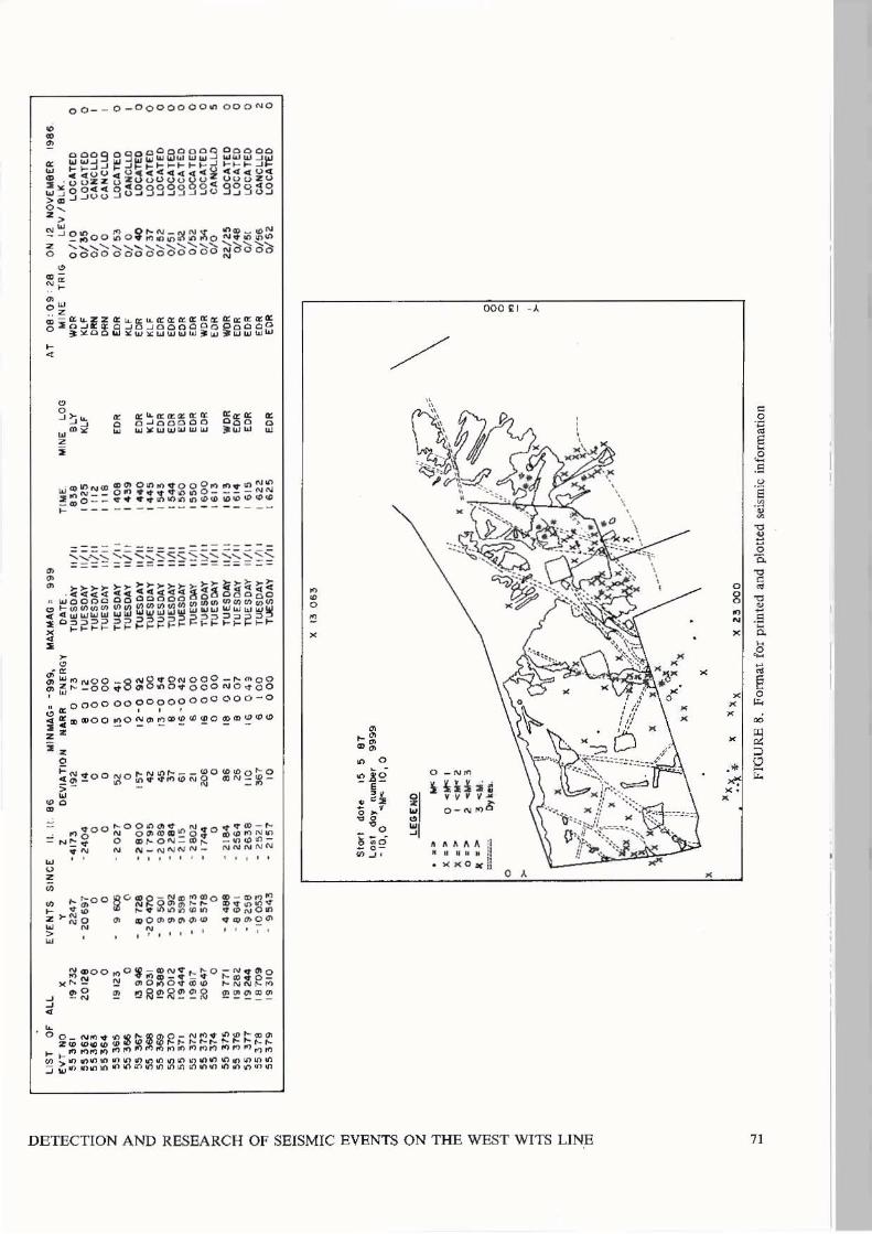
seconds. See Figure 7. Once the located information has been
stored in the relevant file, the computers
are efficient at accessing and analyzing , the seismic data. This is shown by the
daily information which is presented to
management and which is used for simple
type analysis. Printouts of the located
information can be obtained within minutes
and simple statistics can easily be
obtained from user written programs.
All this information is shown in
Figures 8 and 9.
These examples indicate that computers
with fast processing speeds are usually
well suited to the location and research
of seismic events. On other systems where
micro-seismic data is being processed and
approximately 100 events are triggered
every hour, computers are unrivalled in
data handling.
Case studies In its five years of operation the Gold
fields Seismic Network has seen the
inclusion of five mines. Priority has
always been given to operation of the
10
system as a management tool, This has
meant that maintenance work to ensure the
rapid location
always taken
development
Unfortunately.
of seismic events has
priority over
and
the
resear ch
system
work.
large amount of
maintenance wo~k, involving both the
underground technical equipment an the
computers themselves. has meant that the
system has not developed toward the
analysis of the accumulated data as it
might have done. Nevertheless, during
this time period several case histories
can be highlighted which show how the development of the system can be measured
against its oYiginal objectives.
On 27 December 1983 a 4.2 magnitude
seismic event shook the Carletonville
area. The intensity at the West
Driefontein offices was particularly high,
and management anticipated it to be
somewhere on the mine. The seismic system
was able to calculate the location and
magnitude of the event within minutes.
The hypocentey was located close to an
area of mining on West Driefontein, and
rescue operations were put into effect
immediately. thus eliminating any wasted
time in trying to establish the area of
concern, and allowing panic reduction in
distant, undamaged areas. As it turned
out. this event caused underground damage
to the surrounding mining excavations.
Five workers were fatally injured and a
total of 89 workers were hospitalized.
Since this incident, several others have
also occurred involving events between 2
and 4 on the Richtey Scale which confirm
that the system has met the required
immediate objective.
The medium term objectives of the
network were involved with seismic
improved aspects of mine planning
including mining layouts and support
MINING: ROCK MECHANICS
~
V Z
W
00- - 0_0000000." OOONO
a: ,z"' ,zo:: ,z a:a: Q C ..l OOOQO .... .... :.,0: ................ 11.1
• o •
w h~oo~Q ~R a~~= fo *; ~~~ ~ ~G ~ ~.~."."G." .~N O." Z~ ~O ~ ~O ~~~~~ .~ ~o~ ~ N , 'i', ' • • , , . • ;- , ~
" • o
" x
~ ~ • • "
000 £1 - A
o _N'" !k Hh,
v ~ f V'" O_Nrtl S
~ ~ ~ ... A ;1 •• M •• i!
>0( >< 0 ~ ;I o ,
DETECTION AND RESEARCH OF SEISMIC EVENTS ON THE WEST WITS LINE
•
o g
" N
X
X X
• •
. '
71

GESA SEISMIC NETWORK
DISTRIBUTION Cf EVENTS >1. ~ DURING AUGUST 19B4
BLY 22.14 · 5% -
--------~:;;:~t=i==f~~~~-----------DKL 4-2 . 6"10
WDL __ -\ 59=39%
-
~-__ DRN 18.11.9%
KLE 15<9·9'10
L-______ WDR
26.17.2% FIGURE 9. Graphical representation of s,eismlc information
methods. Two examp les have been used to
show ho\o1 the sys tern is meeting some of its
roles ellv~saged in the medium tern .
Figure 10 shows the locality plan of a
shaft pillar complex on West Driefontein
t hat is presently being ext racted. In
J uly 1986 mi ning conditions in the area
began to deteriorate, and the Rock Mec hanics departme nt was asked to
investigate the methods of mining in the
area. The seismic data far the area was
included in a report . Prior to t he
deterioration the area had been mined i n
both easterLy and westerly directiDns from
the 14-1 ) Carbon Leader raise (see Figure
10). Min ing in a westerly di rection was
72
progressing to~ards a geological fault
structure and was stopped purely by
accident in about January 1986 owing to
labour prob J. ems . Mining was subsequent l y
continued in an easterly direction onl y
from February to J ul y 1986 . After this
period mini ng was again anticipa t ed on t he
westerly pane l s. and the Rock Mechanics
department was asked t o investigate the
situation .
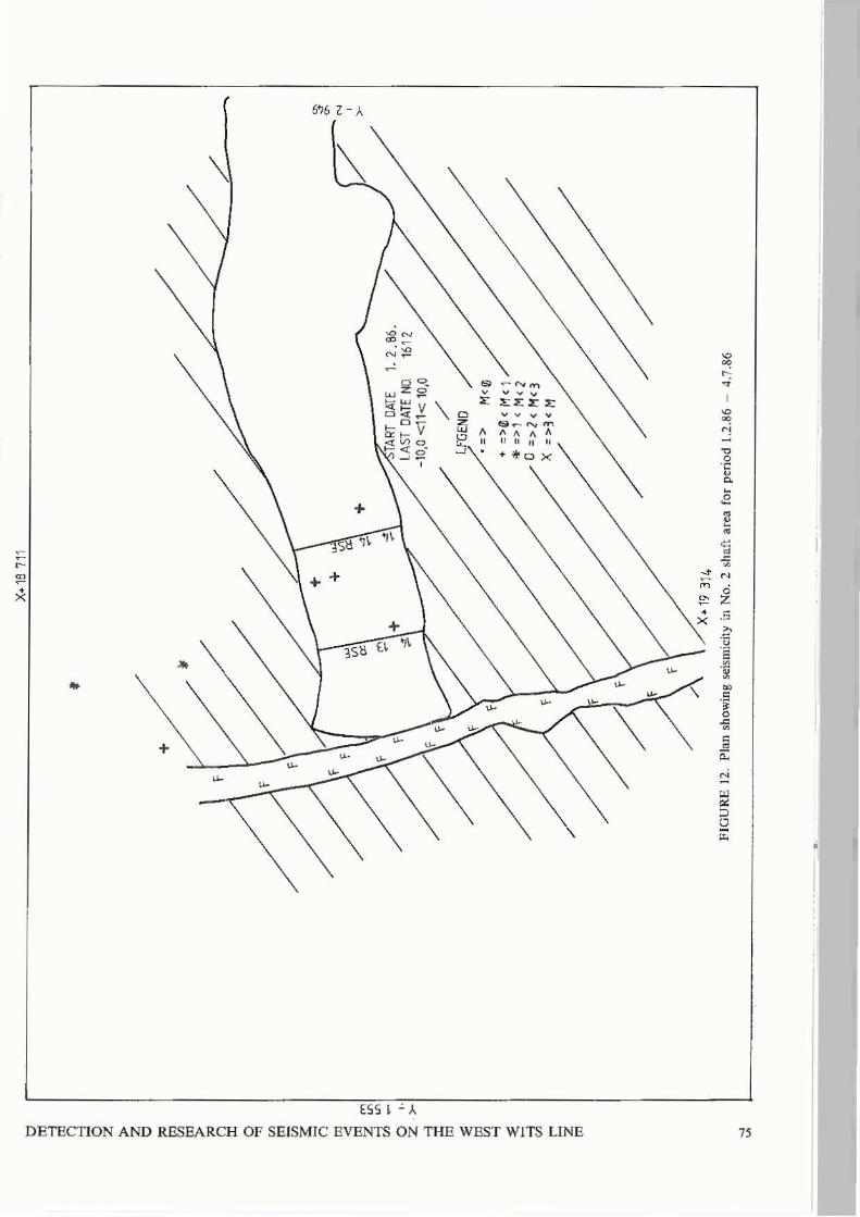
By comparing a Simp le plot of the
seismicity during the periods 1 June 1985
)1 January 1986 (both panels) and
1 February 1986 - 4 July 1986 (east side
only. see Figures 11 & 12), the Rock
Mechanics report was ab le t o show that the
MINING: ROCK MECHANICS
•

k/l~-b-
\ 20
~'
J(\
23
\ <:
) 10
\
19
\:l \
16
\ 11
\
18
'" (1 '" ~
~ 14
15
'6 z ~ <:
) ~
---~ ~ ../'1
# r
....
....
.-1~
~ ~ ~ ~ ~ ~.~ /-~
_./"
'" '" » " g 0 '" '" '" t;; ~ ~ '1 .... '" 0 z ~ "' " &\ .... " ;;i C
~ .~ ~ ~ ~ ....
...... ,
""_13
RO"
---~ ~ ~ ~ ..
-11 ~ ~ ..
....
-f;,
j'~ ~ ..
J ~ ~ ...
J r ~ ~ .....
..... SC
ALE
1100
00
~ ~
.-'
FIG
UR
E \
0. L
OO
''''' p
l.n
of
No.
2 ,
..It
pil
l" c
ompl
" on
Wc"
D,;d
onIC
ln
24
\ 25
~

i i!: Z ~ ~ ~ ~ Cl
m ~
~
~ , ~!
• ..
o + "
X+18
743
..
'/
.~r:;.
.A
, A
.. -
cV' 'ii\ 1-. ,
~,r"
;0
~
+
... 4
-'"
~
. "'"
\1
"
, ..
.. +
/
,
~I
," \
' /'
/'J
' /
/1, %
,.
,
..
FIG
UR
E 1
1. P
lan
sho
win
g se
ism
kity
in
No.
2 s
haft
are
a fo
r
I-I
L
.. ,1
CR
?\C
ci>!\
STAR
T DA
TE /
1.6
.85
. LA
ST D
AY
NO.
1 52
3 -1
0-0
<1
K
1(}-O
LEGE
ND.
'" >-
M""O
+
=>
-O""
M"'
l *" =
:>
' .... H
<2
0
= >
-2<
1'1<
3 X
=:>
3""
M
peri
od 1
.6.8
5 -
30.1
.86
~
~
m
N >'
t>
X+ 1
8 71
1
'" -I
nl B
• ~ ,. z t> '"
+
!Jl /'
, ~
m ,.
/'
L "
\ F I /'
/'
/ n :t
0 ."
/'
IF
'" !!! /'
/ '" l:
+
~ "i
1)
~
t;! +
V
-:
~ §
+
~
(0
J TA
RT D
ATE
1.1
.86.
+
-
0 ,.
" LA
ST D
ATE
NO.
1612
Z
>-
-10,
0 <1
1< 1
0,0
-I
/'
:t
m
:E lfG
ENO
Iil •
=>
M
<.
-I
+ =
:>0<
Hq
:E
*=
>1
<M
<]
~ /0
=>2
< H
<3
C
X =
= >3
( M
Z m
/'
/'
I /
1 .' ,
/\
, "'
X+
19
31
4
FIG
UR
E 1
2.
Pla
n sh
owin
g se
ism
icity
in
No.
2 s
haft
are
a fo
r pe
riod
1.2
.86
-4.
7.86
~
~

~
~ ;:: ~ Cl ::; R ~ r:
, ..,
! SC
AL
E
1'1 6
00
I
y: 8.
:.~~;o:
~.:
'~I:
'-'
>':~
'.
/~
~.
30
F
W O
R
PO
SIT
ION
2
~~\L-<
" ~~ .+
"'91'
I-'V
~IIIU'
" I
1 I
}/
/ >
>~
,. .~.-'
/
~~i
' ~
_,#$.
:;,5
'
''1 .. !y
''~
~.
,
~-
:i::
.: .. :~ .. j;~
'y. .. ':.~:
.' ·i 1- " ,:
~:
?l fA F
IOU
RE
13.
Pla
n o
f p
ropo
sed
posi
tion
s fo
r 30
Lev
el h
aula
ge b
etw
een
No.
3 S
ub V
ertic
al a
nd N
o. 5
Sub
Ver
tical
sha
fts
..--
.-

•
q" OT DATE 1 . C {f5--LAST DAY NUM BER 9999 -1I11. 0< M <: 1ft
o
•
•
+::) aJ<.M< J
*=>l<M<]
O='>1<M<3
X=>3<M
•
o .0 J!:.
MAGNITUDE
FIGURE 14. Plan showing scismicity in the area of proposed 30 Level foolwall drive fo r period 1.1.83 - 1.3.84
DETECTION AND RESEARCH OF SEISMIC EVENTS ON THE WEST WITS LINE
>-
77

westerly mining ~as the main cause of
seismicity ,n the area, rhe
recommendation put forward by the report
was carried out and the westerly panels in
the area ~ere abandoned. Since this
decision no furher problems were
experienced in the area.
A second example is highlighted through
the siting of a footwall haulage to be
connected between two shaft systems on the
West Driefontien Gold Mine (see Figure
13). The existing 30 level haulage
connection also shown on the plan was
damaged in 1984 due to a large seismic
event which was located on the system of
dykes intersecting the haulage. Once again seismic data was used in determining
the best position for this haulage.
Figure 13 shows t he layout of the mining
with the two proposed positions for the
haulage, Figure 14 represents a plot of
the seismicity in the area for the period
1/1/83 - 1/3/84, and Figure 15 a section
of all the events within a 200 m radius of
the line marked x-x on Figure 14.
It can be seen from figure 15 that most
of the seismicity in the area was limited
to within about 100 m of the reef plane.
Also important in the location of this
haulage was a 100 m thick shale horizon
located about 100 m in the footwall of the
reef. The first option for this haulage
(position 1) was found to intersect the
weaker shale horizon. In addition it ~as
intersected by a complicated system of
dykes and it would also have fallen under
the final mining remant in the area.
Consequently the second option (position
2) was chosen as it was situated much
deeper in the footwall and was considered
to be well out of the range of any
possible seismic damage.
As far as the long term objectives are
concerned, the system has not yet met any
78
of its requirements. In recent months, a
large amount of time has been spent on the
development of a data base specifically
for seismic research. This has involved
the writing of a digitizing program that
will be able to store data for any
Variables considered relevant to seismic
research. This will include i nfonnation
such as geological features, sampling
values, induced mining stresses, accident
statistics and support types. Each of these variables will be stored in separate
files on a separate disc volume. It is
hoped that this base of information will
help the system meet more of its medium
term objectives and provide a foundation
on which to base the long term research
projects.
Conclusion The Gold Fields Seismic Network was
established in 1980 in order to monitor
the seismicity occurring in association
with the gold mining operations of the
West Wits Line. The system is an example
of how computers have been used to assist
with a problem that causes the industry
frequent setbacks. Data is transmitted
from a number of remote sites to a central
processing station at speeds of 48 K baud.
The system uses Perkin "Elmer mini-
computers to achieve these goals. rhe
speed and efficiency of the computers in
handling the necessary data mean that
seismic events can be located within the
space of about 3 4 minutes. Further
analysis on this data can be carried out,
and several examples have been outlined to
show that computers are ideally suited to
this area of study.
Although the present system uses mini
computers in this particular application,
it is by no means true that they are the
only type of hardware suited to the task.
It is possible to set up seismic systems
MINING: ROCK MECHANICS

s I g N , N
o
I
I
I
I
o
+ o
I
I
I
•
+
I + I
I
I I
.. + /
I /
I
/ . • •
I
I
I I
I
o
I
I I
/ I ,.
o I •
+
DETECTION AND RESEARCH OF SEISMIC EVENTS ON THE WEST WITS LINE
ES1 6~
S9E 6~ 0
, N
79

using smalle r micro computers. Most of the
technical breakthroughs which have taken
place in the micro-computer indus try over
the las t 10 years were not avai lable in
the 19705 when mos t o[ t he exist i ng
netwo rks wer e designed. The type of
hardware chosen for any seismic
appl i cat ion wil l depend largely on the
object i ves of that system. The GoLd
Pie l ds Network was des i gned as a
centralized computer system because of its
siz e, the speed of data transfers
req uired, the large amount of data
handling and the mi nimum staff
req ui rement .
References
1 .JANISCH,P.R. Turning geo logy to
80
accoun t . Economic risk and return on
t he Wes t Wits Line. Geocongress'86.
Extended Abstrac ts, Geological
Society of South Africa. 1986. pp. 229-
232.
2. DE. JONGU ,C.L. and KLOKOW,J.W. The use of
a seismic network as a management
tool. 5th International Congress on
Rock Hechanics. Melbourne Australia,
1983 , Section D pp 101-107
3 .COOK, N.G .W.
rockburs t s .
SymposiUJ1J
University
Sei smic l ocation of
Proceedings of the fifth
on
of
Rock Mechanics.
Minnesota, May 1962 .
Oxford,Pergmon, 1963. pp. ~93 -516.
/1. ECCLES ,C.D.and RYDfffi,J . A. Seismic
location algo rithms: a comparative
evaluation . Rockbursts and Seismicity
in Hines . Johannesburg,Sout h African
Institute of
19B~. pp 89-92
Mini ng & Metallurgy.
MINING: ROCK MECHA NICS


