Download - The Little Wonder Modular - Motocraft

Part Number: 95-0024 REV C – April 2019
The Little Wonder Modular
145-180 GPD
530-681 LPD
Installation, Operation & Maintenance

Revision History
Revision Description Date
A Initial Release May 2017
B Cleaning Procedure Update June 2018
C Various Design Updates April 2019

The following are the types of flags used in this technical manual. They designate safety related items and important operational instructions and should be given special attention when they appear in the text:
Text formatted in this manner concerns an operating procedure or practice that, if not strictly observed, can result in injury to personnel or loss of life.
Text formatted in this manner concerns an operating procedure or practice that, if not strictly observed, can result in damage to or destruction of equipment.
Text formatted in this manner concerns an operating procedure or
MODEL:
SERIAL NUMBER:
DATE OF PURCHASE:
PURCHASED FROM:
INVOICE #:
VESSEL NAME:
INSTALLED BY:
DATE OF INITIAL START-UP:
WARNING
CAUTION
NOTE

� ߪ¿·¿¾» º±® ïîÊô îìÊô ïïðÊôîîðÊ°±©»®«°°·»¿±©²
�
� б©¼»® ½±¿¬»¼ ³±«²¬·²¹ ¾®¿½µ»¬·²½«¼»¼
� ݱ²¬®± ³¿²·º±¼ °®»«®» ®»¹«¿¬±®»²«®»½±²·¬»²¬°®»«®»¿²¼°®»ª»²¬±ª»®±®«²¼»®°®»«®·¦¿¬·±²±º¬»«²·¬òß¼¶«¬¿¾»¬±¿±©±°»®¿¬·±²·²¾®¿½µ·±®º®»©¿¬»®
� °®±¼«½¬·±²
� Ø·¹ «¿·¬§ °·®¿ ©±«²¼ ÌÚÝ®»ª»®»±³±·³»³¾®¿²»
� Ó¿¹²»¬·½ ¼®·ª» ¾±±¬ °«³°
� °®»«®»¹¿«¹»
� Ø·¹ °®»«®» °«³° ·³°»®ª·±«¬±¬»½±®®±·ª»»¿©¿¬»®»²ª·®±²³»²¬¿²¼¼»·¹²»¼º±®³¿·³«³
Ê·´´¿¹» Ó¿®·²» ÔÉÓ Í»®·»Ó±¼«´¿® É¿¬»®³¿µ»®ïìëóïèð ÙÐÜ � ëíðóêèï ÔÐÜ
ݱ²¬¿½¬ ײº±®³¿¬·±²æ
îêíðÛòÛЮ»·¼·±Í¬®»»¬Ý¿®±²ôÝßçðèïð
°¸±²» íïð êðè ëêð𺿨 íïð êðè ëêçî
É»¾·¬»æ
Í¿´»æ
Ì»½¸ Í«°°±®¬æ©¿¬»®¬»½à°¿®µ»®ò½±³
ݱ³°¿½¬ ¿²¼ ®»´·¿¾´»«°°´§ ±º º®»¸ ©¿¬»®òÚ±® ¿·´¾±¿¬ ¿²¼ ±¬¸»®³¿®·²» ¿°°´·½¿¬·±²ò
̸» Ô·¬¬´» ɱ²¼»® øÔÉÓ÷ Í»®·» ®»ª»®»
±³±· ¼»¿´·²¿¬·±² §¬»³ ¿®» ¬¸»
°®»º»®®»¼ ½¸±·½» º±® ¾±¿¬»® ©¸± ®»¯«·®»
³¿´´ô ´±© °±©»® ©¿¬»®³¿µ»®ò
̸» «²·¬ ¿®» ·³°´» ¬± ·²¬¿´´ ¿²¼ »¿§
¬± ±°»®¿¬»ò ×¼»¿´ º±® ¿°°´·½¿¬·±² ©¸»®»
°¿½» ¿²¼ °±©»® ¿®» ´·³·¬»¼ò ̸» ¯«¿´·¬§
½±³°±²»²¬ ¬¸¿¬ ¹± ·²¬± ¬¸» ÔÉÓ «²·¬
»²«®» ¿º»¬§ ¿²¼ §»¿® ±º ®»´·¿¾´» »®ª·½»ò
Ê·¿¹»Ó¿®·²»ÔÉÓïìëóïèð

ÉÐÊÓÌïóîðïç
Ó±¼»´ ﮬ Ò«³¾»®Û´»½¬®·½¿´ Í«°°´§
ʱ´¬ ñ и ñئ ñß³°Ý¿°¿½·¬§
ÙÐØó³í ñ ÜÉ»·¹¸¬´¾ò ñ µ¹
ÔÉÓóïìë çðóèîððçðóèêîî
ïîÊñïëß³°îìÊñéòëß³°
êñîí ïëðñêè
ÔÉÓóïèðöö çðóèëïîçðóèëçê
ïîÊñîîß³°îìÊñïïß³°
éòëñîèòì îîëñïðî
çðóèëïêçðóèëïë
ïïðñïñêðñêòêîíðñïñëðñíòí
éòëñîèòì îéëñïîë
öÓ»³¾®¿²»»»³»²¬¿®»±¼»°¿®¿¬»§ööߧ¬»³®»«·®»î ííóíððï°»®§¬»³
Í°¿®» ¿²¼ ݱ²«³¿¾´»
ﮬ Ò«³¾»® Ü»½®·°¬·±² ﮬ Ò«³¾»® Ü»½®·°¬·±²
èëóððëð Ы³°Ñ· çðóîëïî Ó»³¾®¿²»Ñóη²¹Õ·¬
ííóðïïé ë³·½®±²Ú·¬»® ìðóðîìï Í¿·²·¬§Ð®±¾»
ííóðíïï Ý¿®¾±²Ú«Ú·¬»® èëóðïðî Ý»¿²·²¹Õ·¬
ííóíððð Ó»³¾®¿²»Û»³»²¬ÔÉÓïìë èëóðïðí Ю»»®ª¿¬·±²Õ·¬
ííóíððï Ó»³¾®¿²»Û»³»²¬ÔÉÓïèðöö éðóêïèï Õ·¬ôЫ³°ô᫬·²»Í»®ª·½»
ííóíðíè Ó»³¾®¿²»Û»³»²¬ÔÉÓïìëööö ççóïççðß Ü·¹·¬¿Ø¿²¼»¼ÌÜÍÓ»¬»®
çðóðððë Ú·¬»®Ø±«·²¹Ñóη²¹ éðóððíê Þ»¬ôÓ±¼»ïìë
ççóêèèï Ú·¬»®É®»²½ éðóðïêè Þ»¬ôÓ±¼»îðð
éðóêïèï ØÐЫ³°Í»®ª·½»Õ·¬
ööߧ¬»³®»«·®»î ííóíððï°»®§¬»³öööÌ·«»¼º±®°¿®»±²§·²¹»ìðþª»»ò
Õ»§ Ú»¿¬«®»
Ñ°¬·±²¿´ ¿´·²·¬§ ³±²·¬±® ¿²¼ ¼·ª»®·±² ª¿´ª» §¬»³ º±®
©¿¬»® ¯«¿´·¬§ ¿«®¿²½»ò
Í¿´·²·¬§ ³±²·¬±® ¿²¼ ¼·ª»®·±² ª¿´ª»
ÐñÒ çðóððèï ïîÊ
ÐñÒ çðóðïïì îìÊ
ÐñÒ çðóðïïë ïïðÊ
ÐñÒ çðóðïïê îîðÊ
̱³¿·²¬¿·²°»¿µ°»®º±®³¿²½»¿©¿§«»¹»²«·²»Ð¿®µ»®Ê·¿¹»Ó¿®·²»®»°¿½»³»²¬
ÉßÎÒ×ÒÙæ Ì·°®±¼«½¬½¿²»°±»§±«¬±½»³·½¿·²½«¼·²¹Ü·øî󻬧»§÷°¬¿¿¬»øÜÛØÐ÷ô©·½·µ²±©²¬±¬»¬¿¬»±ºÝ¿·º±®²·¿¬±½¿«»½¿²½»®¿²¼¾·®¬¼»º»½¬±®±¬»®®»°®±¼«½¬·ª»¿®³òÚ±®³±®»·²º±®³¿¬·±²¹±¬±©©©òÐêëÉ¿®²·²¹ò½¿ò¹±ªò
ÿ


LWM-145 to LWM-180 Manual 1 Revised 04/2019
LWM series Seawater Desalinator is a single-pass purification system that uses
reverse osmosis (RO) to produce potable water from seawater. Product water
with salt concentrations of < 500 ppm are achieved by removing approximately
99% of the dissolved salt in seawater.
1. INSTALLATION
The RO unit should be installed in a dry, sheltered location protected from direct weather. Drainage should be provided beneath the RO unit to allow standing water to drain when performing maintenance or repair.
Refer to the Plumbing Diagram for arrangement and connection hose sizes. All
connections up to and including the boost pump must be below water line. If necessary, the three-way flushing valve may be disconnected from the flushing filter to get the valve below waterline. The pre-filter, the HP pump and the membrane rack can all be above the waterline as indicated in the diagram below.

LWM-145 to LWM-180 Manual 2 Revised 04/2019
1.1. INSTALLATION PROCESS
Locate or create a 1/2” dedicated through-hull for the feedwater intake of the RO unit. The through-hull must be attached with a ball valve (seacock), and optionally a sea strainer.
The Little Wonder MODULAR SHOULD NOT SHARE a through-hull feedwater intake. Parker Hannifin recommends the Little Wonder HAVE its OWN dedicated through-hull, to properly feed water into the RO. Avoid connecting the inlet piping to any water line which services an engine or other equipment. Air could be drawn through the unit causing damage to the RO unit’s pumps, as well as VOIDING the RO unit’s warranty with Parker.
1.1.1. TO CONNECT PLUMBING
Refer to the EXPANDED detailed Little Wonder MODULAR plumbing diagram.
Figure 1.1: Little Wonder MODULAR Plumbing Diagram.

LWM-145 to LWM-180 Manual 3 Revised 04/2019
INSTALLATION
1.1.2. FEEDWATER INTAKE
Step 1: Mount the sea strainer BELOW the vessel’s waterline.
Step 2: Mount the three-way manual Freshwater Flush Valve (attached to Carbon Filter Housing) BELOW waterline. Refer to Figure 1.2 for a view of the carbon filter and freshwater flush valve.
Figure 1.2: Carbon Filter with Freshwater Flush Valve – Isometric Views.
Parker Hannifin recommends the Manual Freshwater Flush Assembly be installed BELOW waterline. However, the valve can be removed from the filter housing and relocated below waterline, leaving the filter housing ABOVE waterline. A hose can be
plumbed from the filter housing to the valve. This way the seawater feed does not go above waterline to avoid trapping air and creating a priming problem.
Figure 1.3: Carbon Filter with Freshwater Flush Valve – Isometric Views.

LWM-145 to LWM-180 Manual 4 Revised 04/2019
Step 3: Figure 1.3: Connecting the Carbon Filter Outlet to the Separated Freshwater Flush Valve. Connect 1/2” diameter PVC hoses to connect all the feed water components up to the high- pressure pump. Note the boost pump outlet is a 3/8” diameter barb fitting. Use a short section of 3/8” hose and jump to 1/2” diameter using the step size adaptor supplied.
1.1.3. BRINE DISCHARGE Locate a convenient spot in the boat to install an overboard discharge through-hull with an 1/2” diameter. Discharge line is required to be ABOVE waterline, refer to Figure 1.1. If connecting to a common drain, tee in from above so that backflow contamination to the watermaker from other drains is not possible.
1.1.4. PRODUCT WATER AND SAMPLE WATER Connect a 1/4” diameter PVC hose (or potable water hose) from the product elbow off the back of the product flowmeter to a sample valve (Refer to Figure 1.4). On both outlets of the sample valve, connect a 1/4” inner diameter PVC hose (or potable water hose), one hose for product water sampling and the other hose for feeding the ship’s Freshwater Tank. The product tank hose off of the sample valve is to be fed into the top of the product tank, to prevent any possible backflow (refer to Figure 1.1).
Figure 1.4: Little Wonder MODULAR Sample Valve Connection.
If a fitting connection cannot be made to the top of the Freshwater Tank, tee into the Deck Water Fill.
Leave enough hose length to RUN the sample hose portion to a sink, bilge, or overboard, to sample the water.
Parker Hannifin recommends running the sample line to a galley sink and installing a dedicated water spigot, free flowing, always open (i.e. a ‘cane shaped’ fixture as used in a manual galley pump). This allows easy sampling at a sink, a drain overboard and the
capability to fill extra water bottles, while your Little Wonder produces water for all purposes.

LWM-145 to LWM-180 Manual 5 Revised 04/2019
1.1.5. FRESHWATER FLUSH Tap into your boat’s freshwater pressure system (Tee into the cold pressurized side) with a 1/2” diameter hose to the carbon flush filter. If the freshwater pressure on board is above 35 psi, install a pressure regulator.
Inlet and discharge interconnecting lines should be constructed of a NON- FERROUS material. Examples of some suitable materials are PVC, copper-nickel, 316 stainless steel pipe or a reinforced non-collapsing
hose. Ferrous piping introduces iron that will foul the membranes prematurely.
Avoid connecting the seawater source to a water line that services any other piece of equipment. Air could be drawn through the RO unit
causing damage to the RO unit's pumps. Cross contamination is also possible. The best practice is a dedicated through hull for the
watermaker, with a separate seacock and strainer.
Connect electrical power to the watermaker. Select the circuit breaker size of at least 50% more than the operating amps shown on the serial number tag. 110 VAC 60 hertz units need a three-wire supply, black, white and green for hot, common and ground respectively. 220 VAC 60 hertz units need a four-wire supply, black, blue, white and green for hot, hot, neutral and ground respectively - bring a separate neutral from the generator if necessary. 230 VAC 50 hertz units need a three-wire supply, black, white and green for hot, hot, and earth respectively. Connect power to the main terminal block in the electrical enclosure following the above wire colors.
Strictly observe all applicable electrical codes and regulations governing the installation and wiring of electrical equipment. Typical codes specify the type and size of conduit, wire diameter and class of wire insulation
depending upon the amperage and environment. The power supply should always be of a greater service rating than the requirements of the
RO unit. Never connect the RO unit to a line that services another electrical device, the RO unit should have its own breaker.

LWM-145 to LWM-180 Manual 6 Revised 04/2019
Disconnect electrical power to RO unit prior to servicing the watermaker
TURN OFF ALL ELECTRICAL POWER FOR USE WITH THE RO UNIT PRIOR TO CONNECTING TO THE RO POWER SOURCE. FAILURE TO DO SO MAY RESULT IN
SERIOUS INJURY OR DEATH TO PERSONS HANDLING THE UNIT.
Adhere to all electrical codes and regulations governing the installation and wiring of electrical equipment. Typical codes specify the type and size of conduit, wire diameter,
and class or wire insulation depending upon the amperage and environment.
The power supply should always be of greater service rating than the requirements of the RO unit. This will assure proper voltage even if power supply voltage is slightly less than
required. Never connect the RO unit to a line that services another electrical device. THE RO UNIT SHOULD HAVE ITS OWN INDEPENDENT POWER SUPPLY.
Step 1: Verify all power switches and power sources are in the OFF position.
Step 2: Connect power source wire (Positive +) to line side on RO unit’s breaker.
Step 3: AC POWERED 110V/220V Little Wonder MODULAR: Connection will be from the separate control box supplied to the onboard circuit breaker panel. Parker recommends use of a 15-amp fuse or circuit breaker.
DC POWERED 12V Little Wonder MODULAR: 12 VDC units require 6-gauge wire and a 25-amp fuse or circuit breaker. Connect RO unit’s power supply red wire (Positive +) from load side of unit’s breaker, to power input on the Little Wonder MODULAR’s terminal strip.
Step 4: Connect a negative black wire from the ground bus bar behind main breaker
panel to negative power source input on unit.
Step 5: With the DC units, connect the boost pump wires red and black to the same terminals at the side of the high-pressure pump.

LWM-145 to LWM-180 Manual 7 Revised 04/2019
Figure 1.5: LTM (DC UNIT) Electrical Interface View

LWM-145 to LWM-180 Manual 8 Revised 04/2019
2. START UP AND OPERATING PROCEDURE
1) Check the HP pump oil level by observing sight gauge located on the pump. Open the raw saltwater supply to the unit at the through-hull. Also ensure that the flushing valve is in the saltwater position with the valve handle pointing away from the carbon flushing filter. The product sample valve should be in the “sample” position, not directed to tank.
2) Verify the bypass valve (black handle) is open, counterclockwise.
3) Start the LP pump, verify the filter pressure gauge shows >5 psi indicating the system is primed with water.
4) Start the HP pump. Water should now be flowing through the system and discharging through the overboard reject line. Often installations will connect both pumps to the same circuit breaker. This arrangement is acceptable; however, it is still prudent to confirm the pumps are primed and running correctly. Remember, there is no safety switch for low flow, and pump damage will occur if running dry.
5) Slowly close the bypass valve, and confirm that the membrane pressure gauge registers 800 psi. The high-pressure setting can be adjusted by the regulator set screw on the high-pressure manifold on top of the instrument panel.
6) After 2 minutes of operation, confirm the salinity by taste test or by hand meter at the sample valve. Once it is acceptable, turn the sample valve to direct water to your storage tank. A digital salinity monitor and automatic diversion valve is
available as an option.
7) Now, would be a good opportunity to record the pressures, flow and salinity on the Operation Log.
8) For shutdown, reverse the steps. First open the black bypass valve. Then shut down the HP and LP pumps. Turn the product sample valve back to sample position. If you are unsure if the watermaker will be restarted in a day or so, now is time to flush the watermaker to keep the membranes fresh while idle, please see the next section. Bacteria and biological growth increases, the longer stagnant water is in contact with the membranes, so the flushing is advised whenever the unit will be idle. Once flushed, the flush should be repeated once every one or two weeks, if the idle period continues. For extended periods, see the section on pickling or preserving the watermaker.

LWM-145 to LWM-180 Manual 9 Revised 04/2019
3. MAINTENANCE
The service life of most system equipment is directly related to the raw water inlet conditions. Improper maintenance will also significantly reduce the life expectancy of the major unit components (such as the membranes, filters and pumps), as well as the reliability of the unit as a whole. Under normal conditions, and with proper maintenance, a reverse osmosis membrane (which is the major consumable item) should have an effective service life
The RO unit must be cleaned when product water production output drops by 20%.
Daily
Wee
kly
Mon
thly
Qua
rterly
Sem
i-Ann
ually
Ann
ually
As
Req
uire
d
Labo
r Hou
rs
(app
roxi
mat
e)
Clean/inspect micron pre-filter •
0.5
Replace filter(s)*
• 0.5
Clean membranes • 2.0
Replace Membranes • 1.0
Check pump oil level •
0.1
Change pump oil** • 0.5
Lubricate pump motor • 0.5
Table 3.0: Maintenance Task Chart.
* Parker pre-filter cartridges can be rinsed with freshwater and be reused up to 3 times. ** Change pump oil after first 50 hours of RO use. After the first oil change at 50 hours, change the pump oil every 500 hours thereafter or once annually which ever interval comes first.

LWM-145 to LWM-180 Manual 10 Revised 04/2019
4. FRESHWATER FLUSH / SHORT TERM STORAGE
Ideally, the system performs optimally when the RO unit is used regularly. The likelihood of bacterial and biological growth in the membranes increases, when stagnant seawater (in extended periods) is in contact with the membranes. A freshwater flush procedure is necessary to prevent clogging and growth of organic contaminants in the RO system and its membranes. This method pushes out older stagnant seawater (saltwater) out of the membranes and replaces it with freshwater (non-saltwater), leaving less chance of fouling the membranes. The freshwater flush procedure should be used when the unit will be placed idle or in "stand by" condition for more than several days OR idle for three days in hot, tropical climates. Although they do not attack the membranes or other system components directly, high concentrations of biological matter can block enough of the product water channels to cause a reduction of as much as 40% of the total system capacity.
Perform a freshwater flush to the RO unit with non-chlorinated fresh water only. Exposing the membranes to chlorinated water will cause irreversible damage and void the RO unit
warranty. The freshwater flush system uses a carbon filter inline before the system to consume the chlorine that may be present from the dock water.
LWM-145 to LWM-180 Manual 11 Revised 04/2019
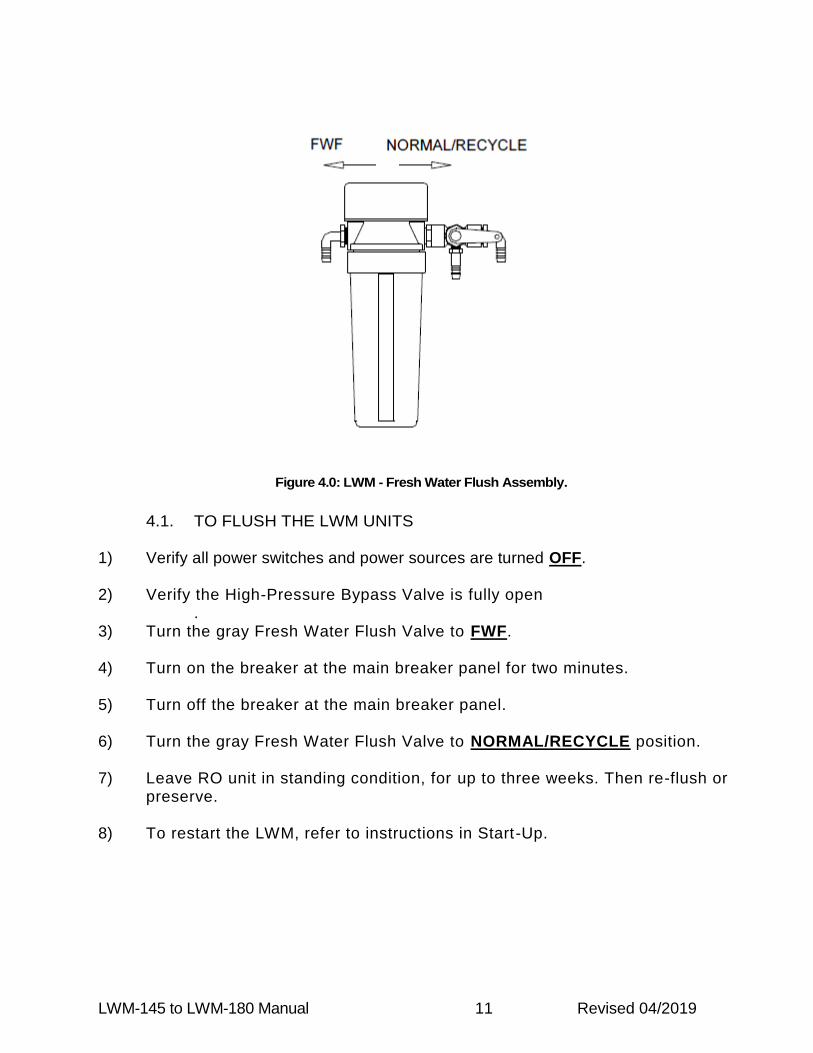
Figure 4.0: LWM - Fresh Water Flush Assembly.
4.1. TO FLUSH THE LWM UNITS
1) Verify all power switches and power sources are turned OFF.
2) Verify the High-Pressure Bypass Valve is fully open .
3) Turn the gray Fresh Water Flush Valve to FWF.
4) Turn on the breaker at the main breaker panel for two minutes.
5) Turn off the breaker at the main breaker panel.
6) Turn the gray Fresh Water Flush Valve to NORMAL/RECYCLE position.
7) Leave RO unit in standing condition, for up to three weeks. Then re-flush or preserve.
8) To restart the LWM, refer to instructions in Start-Up.

LWM-145 to LWM-180 Manual 12 Revised 04/2019
4.2. MEMBRANE CLEANING
The membrane elements require occasional service; it is recommended to clean the membranes only when dirty. Basic procedure for all cleaning and preservative treatments is similar; a specific chemical solution is circulated through the system for a pre-determined length of time.
All cleaning and preservation procedures should be performed with NONCHLORINATED freshwater to optimize performance of cleaning process.
Allow your unit’s product water to run with product to DUMP for the first 30 minutes after cleaning or upon startup after preservation.
Part # Description Cartridge
85-0102 Cleaning Chemical #1 Cleaning Chemical #2
Cartridge (Blue Stripe) Cartridge (Red Stripe)
85-0103 Preservative Chemical #3 Cartridge (Green Stripe)
Table 4.0: Chemical Cartridge Requirements
4.2.1. CLEANING CHEMICALS
Cleaning chemical #1 is an alkaline detergent, used to remove oil, grease, biological matter, and grime from the surface of the RO membranes. See warning label on side of
package and observe all safety precautions on label.

LWM-145 to LWM-180 Manual 13 Revised 04/2019
Cleaning chemical #2 is an acid, a mineral scale remover. See warning label on side of
package and observe all safety precautions on label.
THE USE OF CHEMICALS OR CLEANING METHODS OTHER THAN THOSE OUTLINED IN THIS MANUAL WILL VOID THE RO UNIT WARRANTY. NON-IONIC
SURFACTANTS USED FOR MEMBRANE CLEANING OR ANY OTHER CHEMICALS NOT APPROVED IN WRITING BY PARKER, WILL VOID THE RO
UNIT WARRANTY.
4.2.2. WHEN TO CLEAN Chemically clean the RO, when product water output drops below 80% of original production. The frequency of this occurring varies greatly upon feed water. Membrane fouling will occur with normal use.
Product water output depends on feedwater temperature, pressure and salinity. Product water output reductions from these factors are normal and may not
indicate need for membrane cleaning.

LWM-145 to LWM-180 Manual 14 Revised 04/2019
STEPS FOR CLEANING CHEMICALS #1, #2, AN D #3 (CARTRIDGE FORM)
CLEANING PROCEDURE
1. Fresh water flush system for 7 minutes.
2. Remove Pre-filter and replace with cleaning
cartridge filter (Chemical #1 – Blue Stripe), then
fill housing with unchlorinated water. Screw
housing back into place.
3. Fully open the High-Pressure Bypass Valve for
Cleaning Mode.
4. Open cleaning valve at bottom of manifold.
5. Turn product sample valve to center of product
and reject.
6. Start R.O. unit running booster pump only.
7. Close fresh water flush valve, putting valve
handle in center.
8. Allow the cleaning to run for 30 minutes.
9. Turn system off.
10. Remove cleaning cartridge and replace with 5-
micron pre-filter.
11. Close cleaning valve at bottom of manifold.
12. Turn fresh water flush valve to sea water
position.
13. The system is ready to run like normal. (Allow
system to run for 5 minutes to flush out all
cleaning chemical.)
14. If necessary, use Cleaning Chemical #2 (Red
Stripe), repeat Step 1 – 9.
15. Return R.O. to Normal Conditions.
16. Record production flow rate before and after
cleaning to determine effectiveness.
PRESERVATION PROCEDURE:
1. Fresh water flush system for 7 minutes.
2. Remove Pre-filter and replace with preservative
cartridge filter (Chemical #3 – Green Stripe), then
fill housing with unchlorinated water. Screw
housing back into place.
3. Fully open the High-Pressure Bypass Valve for
preservative recirculating.
4. Open cleaning valve at bottom of manifold.
5. Turn product sample valve to center of product
and reject.
6. Start R.O. unit running booster pump only.
7. Close fresh water flush valve, putting valve
handle in center.
8. Allow the preservative to run for 30 minutes.
9. Turn system off.
10. Remove preservative cartridge from pre-filter
housing, then replace filter housing bowl to filter
housing top empty.
11. Leave all valves in position they are in now.
12. Unit is now preserved.
For resuming normal RO operation (“unpreserving” or “unpickling”), install a 5-micron fi lter into pre-fi lter housing and fi l l it with UNCHLORINATED WATER,
Begin system Start-Up Procedures.
If RO unit storage time is to exceed four months, then it is NECESSARY to Flush (Push Out) the existing chemical out of the unit and represerve at EVERY
FOUR MONTH INTERVAL.

LWM-145 to LWM-180 Manual 15 Revised 04/2019
5. OIL CHANGE PROCEDURE
An oil change is recommended after the first 50 hours of RO use. Subsequent oil changes are to be performed every 500-hour intervals OR changed annually. Change oil any time moisture is detected or if oil is cloudy. For additional pump information, refer to MANUFACTURER’S LITERATURE in back of this manual.
DO NOT RUN PUMP WITHOUT OIL IN THE CRANKCASE.
Step 1: Turn off all power sources and switches.
Step 2: Before changing the oil, obtain a container (i.e. tray or catch basin) to collect the oil
drainage.
Step 3: Remove the oil plug (Refer to Figure 5.1) and direct the oil to a catch basin. Allow the
oil to drain empty.
Step 4: Reconnect the oil plug or oil drain stopper. Then unscrew the oil cap and refill oil to fill
line (located on HP Pump sight glass). Check for leaks and re-secure oil cap.
Figure 5.0: High Pressure Pump Service Locations

LWM-145 to LWM-180 Manual 16 Revised 04/2019
OPERATION LOG
We encourage operators to keep a simple operation log for the watermaker. Even occasional entries will help in troubleshooting. It is especially important to record performance after the first 3 hours after installation, so the baseline is known.
Date Filter Pressure
Membrane Pressure
Product Flow
Water Quality TDS (ppm)
Water Temp, Comments

OPERATION
LWM-145 to LWM-180 Manual 17 Revised 04/2019
6. OPERATION
6.1. TO START THE LITTLE WONDER MODULAR UNIT
Figure 6.1: Little Wonder MODULAR Instrument Detail.
Step 1: Turn the sample valve to SAMPLE position to direct the flow of water to the
sample line. Step 2: Turn the High-Pressure Bypass Valve (Black Valve) to CLEANING position,
counterclockwise, to release air trapped within the system. Verify the Cleaning Valve (Gray Valve) is positioned to NORMAL discharge,
allowing brine water to flow overboard. Also check the gray Freshwater Flush Valve (Refer to Figure 2.3) is positioned for seawater intake, NOT freshwater.
Failure to open the high-pressure bypass valve could result in hydraulic shock to the system. Step 3: Verify the seawater intake is open at the through-hull. Start-up time can be
expedited by filling the pre-filter housing by temporarily turning the flush valve to freshwater position before the RO unit is turned on.

Step 4: AC POWERED 110V/220V Little Wonder MODULAR Models:
Turn Power Switch ON located on the unit’s supplemental control box, to start RO. Start the LP Booster pump first, then the HP Pump.
DC POWERED 12V Little Wonder MODULAR Models: Switch ON the breaker at the main breaker panel to power up the unit.
Step 5: Upon initial start-up inspect all plumbing connections in the unit for leakage.
Varying temperatures during shipment may cause plumbing connections to seep when starting the RO unit for the first time. Secure the unit and repair any leaks before proceeding. Once the leaks are repaired, open the raw water source and restart the unit.
Step 6: Verify brine discharge is flowing overboard. If so, gradually turn the High-
Pressure Bypass Valve (Black Valve) to NORMAL/RO position. The High-Pressure Regulator is factory set at 800 psi. If High-Pressure Gauge does not read 800 psi, slowly tighten or loosen in small increments the screw atop the High-Pressure Regulator and adjust to a reading of 800 psi. For location of High-Pressure Regulator, refer to Figure 4.1.
If the RO unit is used for other than seawater purification (in freshwater or brackish water applications), reduce pressure as necessary to achieve product flow no greater than 120% of
design flow to avoid membrane damage.
RO HIGH-PRESSURE PRODUCTION SHOULD NEVER EXCEED 950 PSI, DOING SO RISKS DAMAGE TO THE RO UNIT VOIDING FACTORY WARRANTY.
At initial start-up of RO unit, keep the product water diverted out of the water storage tank. IF the unit is filled with preservative storage solution, production must be diverted AT LEAST 10
MINUTES to clear preservative solution from system. Step 7: With the Sample Valve at SAMPLE position, taste the water quality or test it with
a hand-held test meter. If quality is good, turn the Sample Valve over to PRODUCT direction, routing the product water into the vessel’s storage tank.

Step 8: Check the RO unit for water leakage periodically at the initial start-up. Observe
Product Flow meter. Record the product flow after 3 and 24 hours of operation (use the start-up sheet provided).

LWM-145 to LWM-180 Manual 20 Revised 04/2019
6.2. TO SHUT DOWN THE UNIT
Step 1: As the RO unit operates, turn the High-Pressure Bypass Valve (Black Valve) to CLEANING POSITION. This will release the high-pressure within the RO system.
Step 2: AC POWERED 110V/220V Little Wonder Models:
Turn the HP pump off, then the booster pump, off at the control box. Then turn OFF your breaker at the main breaker panel.
DC POWERED 12V Little Wonder MODULAR Models:
Turn OFF your breaker at the main breaker panel.
The RO unit may be left int his “stand-by” condition with seawater for one day. If the RO unit will be out of service for extended time periods, please refer to the Maintenance section of this manual for flushing instructions.

LWM-145 to LWM-180 Manual 21 Revised 04/2019
6.3. PRESSURE VESSEL AND MEMBRANES - DISASSEMBLY
Step 1: Disconnect plumbing from pressure vessel for disassembly. Remove the pressure vessels to a workbench to continue.
Step 2: Remove the six fasteners and cap ring holding each end plug with an Allen wrench. Place a mark on each end plug to be removed, place a corresponding mark on each end collar. This will ensure proper orientation during assembly. See bulletin at the back of the manual for part numbers of the individual components.
Step 3: Locate the screwdriver slots located on opposite sides of the pressure vessel end collar. Place an appropriately sized slot screwdriver in each slot. Twist both screwdrivers until the end plug breaks loose from the pressure vessel. A prying motion on both sides of the end plug with the screwdrivers will quickly remove it. Use this procedure for both end caps. Push or pull the membrane element out of the pressure vessel tube.
Never force a membrane out of a pressure vessel by applying pressure on the product water tube (center tube), as this will damage the membrane. If membrane is difficult to
remove, use a 2” diameter plastic pipe (PVC) to apply pressure on the protected end of the membrane.
Step 4: Note which end of the pressure vessel the brine seal was installed at. The brine seal is a black u-cup seal on the membrane outer diameter near one end. This is the feed end of the pressure vessel. When reinstalling the RO membrane, the brine seal must be located at the feed end of the pressure vessel.

LWM-145 to LWM-180 Manual 22 Revised 04/2019
6.4. PRESSURE VESSEL AND MEMBRANES - REASSEMBLY
Step 1: Inspect all O-Rings; product O-Rings, end plug O-Rings, and Brine Seal. Replace seals if there is visible damage. The product water O-Rings are internal O-Rings, inside the center hole in the end cap.
Step 2: Lubricate O-Rings and entrances to pressure vessel with glycerin or silicone lubricant. Locate discharge end of pressure vessel. Install discharge end plug by lining up with the holes of the pressure vessel, paying attention to the reference mark. Position end cap ring and insert fasteners by hand.
Never use any type of lubricant containing petroleum oil. Oil can damage your unit and reduce membranes performance.
Step 3: Align the membrane so the end without the brine seal enters the feed end of the pressure vessel first. Slide membrane into pressure vessel until resistance is felt. Continue applying pressure until the product water tube sits into the end plug.
Step 4: Install the remaining end plug (align end plug holes with mounting holes properly), use the reference mark made in Step 2 for correct assembly. Tighten the six fasteners for each end cap. Install the vessels and reconnect plumbing.
Do not apply Teflon tape or sealant to straight thread fittings such as those used on High-Pressure hose ends.

LWM-145 to LWM-180 Manual 23 Revised 04/2019
7. TROUBLESHOOTING
Below is a list of frequently encountered operational problems and some guidelines and troubleshooting checks. This section can only be a guide to solving potential problems with the RO unit and does not contain all possible malfunctions. The best troubleshooting tool is your knowledge of the RO gained through experience. Situations not covered in this section may be resolved by contacting Parker Hannifin via phone calls and e-mail.
1. Check for proper valve configuration. Make sure the cleaning valve is in the overboard “Normal” position. Confirm by checking water is flowing overboard through the brine discharge. Flow should be about 1 quart per minute.
2. Always check for loose connections or broken wires when checking electrical parts. Check for good voltage at the high-pressure pump motor; and if it is low then follow back with the voltmeter until the loose connection is found.
3. Confirm that a free sea water feed is supplied. A) The through-hull is clear of trash or kelp. B) Seacock is open. C) Sea strainer is clear. D) Boost pump is running. E) 5-micron filter is clean.
4. To flush the unit, the black handled Bypass Valve is in CLEANING position, but the gray handled Cleaning Valve must be in the NORMAL position. During flush, water must be flowing overboard through the brine discharge.
5. Low production GPH may be caused by cool seawater. Poor salt rejection may be caused by warm and/or salty seas. Do not interpret environmental factors as equipment problems.
LWM-145 to LWM-180 Manual 24 Revised 04/2019
PLUMBING DIAGRAMS
8. PLUMBING DIAGRAMS


-=DD>8
4A
@7
8B
.A
7E
>5
B$
'(
!%
##
!.
5=@
/5
BDC
08
98
B8
@6
8
3=>>5
;8
.5
B=@
82
86
"
+B
8C
<F
5D8
B+
BA
?D<
81
85
.)
0*
,%
#$
&

SYSTEM UPGRADEAS OF 3/1/2016


SYSTEM UPGRADE
AS OF 2/15/2019

SEAW
ATER IN
LET
FR
ESH
W
ATER
IN
LET
PO
TABLE W
ATER
TO
TAN
K
SAM
PLIN
G
REJECT D
ISCH
ARG
E
OVERBO
ARD
FLU
SH
FILTER
FLU
SH
VALVE
LP PU
MP
5 M
ICR
ON
PR
EFILTER
FILTERE PR
ESSU
RE
GAU
GE
HP PU
MP
SYSTEM
M
AN
IFO
LD
MEM
BR
AN
E RACK
3/8" H
P H
OSE
1/2" H
OSE
1/2" H
OSE
1/2" H
OSE
1/2" H
OSE
1/4" H
OSE
1/4" H
OSE
1/4" H
OSE
CLEAN
IN
G VALVE
LW
M-1
45 T
O L
WM
-180
PL
UM
BIN
G D
IAG
RA
M
1/2" H
OSE
1/2" H
OSE
1/2" TEE
3/8" H
OSE
1/2" H
OSE
3/8" H
B TO
1/2" H
B
AD
APTER

Pre
-filt
er A
ssem
bly
p/n
90-3
272
Rep
lace
men
t Ele
men
t p/n
33-
0117
Rep
lace
men
t O-R
ing
p/n
85-0
102
Filt
er P
ress
ure
Gau
ge, p
/n 4
0-03
00
Fre
sh W
ater
Flu
sh F
ilter
Ass
embl
y p/
n 90
-128
8R
epla
cem
ent E
lem
ent p
/n 3
3-03
11R
epla
cem
ent O
-Rin
g p/
n 85
-010
2F
lush
val
ve p
/n 6
0-00
14
See
Bul
letin
for
Pre
ssur
e V
esse
l P
arts
, bac
k of
man
ual
LTM
Sys
tem
Man
ifold
Ass
embl
y p/
n V
5020
6000
5 H
P G
auge
Rep
lace
men
t p/n
101
8142
1CC
F
low
met
er R
epla
cem
ent p
/n 8
5012
009
Man
ifold
Reb
uild
Kit
p/n
V50
2060
006
Mem
bran
e E
lem
ent
Mod
el 1
45, 1
Sho
rt M
embr
ane
p/n
33-3
000
Mod
el 2
00, 2
Sho
rt M
embr
anes
p/n
33-
3001
Mod
el 2
00, 1
Lon
g M
embr
ane
p/n
33-3
002
Mem
bran
e O
-Rin
g K
it p/
n 90
-251
2
HP
Pum
pM
odel
145
, 12V
/24V
p/n
800
1206
1M
odel
180
, 12V
p/n
800
1206
0M
odel
180
, 24V
p/n
800
1206
9M
odel
180
, 110
/230
/1/6
0/50
p/n
800
1207
0 P
umps
p/n
70-
6073
C &
70-
6074
C-C
ompl
ete
Ser
vice
Kit
p/n
6101
2051
Pum
p O
il, p
/n 8
5-00
50
LP P
ump
Low
Pre
ssur
e M
ag D
rive
Pum
p 12
V p
/n V
0160
2000
1Lo
w P
ress
ure
Mag
Driv
e P
ump
24V
p/n
V01
6020
002
Low
Pre
ssur
e M
ag D
rive
Pum
p 11
0/1/
60 p
/n 7
0-15
00Lo
w P
ress
ure
Mag
Driv
e P
ump
230/
1/50
p/n
70-
1500
Kit,
Reb
uild
, Pum
p A
ssy
110/
1/60
& 2
30/1
/50
p/n
70-1
502-
K01

éðèÌ·¬¿²Í»®·»Ø·¹¸ Ю»«®» Ì·¬¿²·«³
б·¬·ª» Ü·°´¿§³»²¬ Ы³°
ײ¬¿´´¿¬·±²ô Ñ°»®¿¬·±² ú Ó¿·²¬»²¿²½»
Ê·´´¿¹» Ó¿®·²» éðèóë Ы³°
ﮬ Ò«³¾»®æ çëóððïì
Ê·´´¿¹» Ó¿®·²» éðèóí Ы³°
Ê·´´¿¹» Ó¿®·²» éðèóï Ы³°

TABLE OF CONTENTSINTRODUCTION..................................................................................................................................................................... 1INITIAL START-UP INFORMATION...................................................................................................................................... 2
LUBRICATION .................................................................................................................................................................... 2PUMP FLOW DESIGN........................................................................................................................................................ 2MOTOR SELECTION.......................................................................................................................................................... 3MOUNTING THE PUMP ..................................................................................................................................................... 3DISCHARGE PLUMBING ................................................................................................................................................... 4PUMPED FLUIDS ............................................................................................................................................................... 4
INLET CONDITION CHECKLIST........................................................................................................................................... 5INLET SUPPLY ................................................................................................................................................................... 5INLET LINE SIZE ................................................................................................................................................................ 5INLET PRESSURE.............................................................................................................................................................. 5INLET ACCESSORIES ....................................................................................................................................................... 6
PREVENTIVE MAINTENANCE SCHEDULE......................................................................................................................... 7MAINTENANCE RECORD..................................................................................................................................................... 8TROUBLESHOOTING............................................................................................................................................................ 9SERVICE............................................................................................................................................................................... 12
INTRODUCTION ............................................................................................................................................................... 12TOOLS NEEDED (VERIFY TOOL LIST) .......................................................................................................................... 12DETACHING THE MANIFOLD FROM THE CRANKCASE .............................................................................................. 13
ROUTINE SERVICE KIT ...................................................................................................................................................... 13VALVE ASSEMBLY ROUTINE SERVICE ........................................................................................................................ 13MANIFOLD SEAL ROUTINE SERVICE............................................................................................................................ 14CRANKCASE SEAL ROUTINE SERVICE........................................................................................................................ 15
SERVICING THE CRANKCASE .......................................................................................................................................... 15OIL DRAIN PLUG O-RING REPLACEMENT.................................................................................................................... 17PLUNGER ROD SEAL REPLACEMENT.......................................................................................................................... 17BEARING SIDE PLATE O-RING/SEAL REPLACEMENT ................................................................................................ 18CRANKCASE COVER O-RING REPLACEMENT ............................................................................................................ 19CRANKSHAFT BEARING, CONNECTING ROD-PISTON ASSEMBLY SERVICE ......................................................... 20
SERVICING THE MANIFOLD .............................................................................................................................................. 20INLET/DISCHARGE ADAPTER O-RING REPLACEMENT 708-3 & 708-5...................................................................... 21VALVE ASSEMBLY SERVICING...................................................................................................................................... 21MANIFOLD SEAL SERVICING......................................................................................................................................... 23ATTACHING THE MANIFOLD TO THE CRANKCASE .................................................................................................... 24


LIST OF FIGURESFig. 1: Oil Level Sight Glass Detail. ..........................................................................................................................................................2Fig. 2: Manifold Assembly Removal .......................................................................................................................................................13Fig. 3: Valve Assembly............................................................................................................................................................................14Fig. 4: Orientation for Manifold Seal Servicing ......................................................................................................................................15Fig. 5: Plunger Retaining Bolt Assembly ................................................................................................................................................16Fig. 6: Seal Retainer.................................................................................................................................................................................16Fig. 5: Plunger Retaining Bolt Assembly ................................................................................................................................................18Fig. 6: Seal Retainer.................................................................................................................................................................................18Fig. 7: Manifold Assembly ......................................................................................................................................................................21Fig. 8: Valve Assembly............................................................................................................................................................................22Fig. 9: Orientation for Manifold Seal Servicing ......................................................................................................................................23Fig. 10: Weep Ring Extraction ...............................................................................................................................................................24

LIST OF TABLESTable 1: Approximate Horsepower Required.......................................................................................................................... 3Table 2: Tool List For Pump Service..................................................................................................................................... 12

1
INTRODUCTION
Aqua Pro Pumps “708 Series” High Pressure Pumps are the product of our years of experience in the water treatmentindustry, and have been specifically designed and engineered for corrosive and high-pressure applications. Your newAqua Pro Pump is made with dependable and proven technology to meet your highest demands.
SPECIFICATIONS
Specifications subject to change without notice.
Pump type: Reciprocating Plunger
Oil Type: Village Marine Tec. High Pressure Pump Oil(Part No. 85-0050-quart size)
Maximum Inlet pressure: Flooded to 60 PSIMaximum Fluid Temperature: 120 degrees Fahrenheit (82 degrees Celsius)
ModelNumber Capacity Inlet Port
SizeDischarge Port
SizeDimensions
L x W x H Weight Shaft
708-1 15 GPH .50 NPT .25 NPT 9.125”x 5.5” x 4” 11 lbs. .625708-1 22 GPH .50 NPT .25 NPT 9.125”x 5.5” x 4” 11 lbs. .625708-1 29 GPH .50 NPT .25 NPT 9.125”x 5.5” x 4” 11 lbs. .625708-3 2.3 GPM .75 NPT .5” MS16142-8 7.5”x 6” x 4.5” 18.9 lbs. .650708-3 3.5 GPM .75 NPT .5” MS16142-8 7.5”x 6” x 4.5” 18.9 lbs. .650708-5 8 GPM .75 NPT .5” MS16142-8 11.5”x 9.5” x 5.5” 27.6 lbs. .938
708-1(15 GPH)
708-1(22 GPH)
708-1(29 GPH)
708-3(2.3 GPM)
708-3(3.5 GPM)
708-5(8 GPM)
Number of Plungers: 1 1 1 3 3 5Bore: .707” .707” .707” .707” .707” .707”Stroke: .2” .3” .4” .276” .512” .625”Oil Capacity: 6 oz 6 oz 6 oz 19.5 oz 19.5 oz 32 oz

708 SeriesHigh Pressure Titanium Positive Displacement Pump
2
(2.1)RPMDesired""GPMDesired""
RPMRatedGPMRated
:RPMPumpDesired
INITIAL START-UP INFORMATION
The performance of the pump depends on the entire fluid system and will operate best with the proper installation ofplumbing, operation, and maintenance of the pump.
LUBRICATION
It is recommended that pump be filled with Village Marine Tec’s specially blended high pressure pump oil. To check theoil level, ensure the pump has stopped running. Then look into the sight glass in the side cover. Oil level should be levelwith the mark on the sight glass (Fig.1).
Fig. 1: Oil Level Sight Glass Detail.
PUMP FLOW DESIGN
To drive the pump to give the desired discharge volume for your specific application equation 2.1 is to be used.
PULLEY SELECTION
It is essential that an appropriate pulley size be selected to meet your application needs. Based on the required pumpdischarge volume (in GPM), the correct pulley size can be selected using equation 2.2.
WARNING
This is a positive displacement pump. A properly designed pressure relief safety valve must be installed in the dischargepiping. Failure to install such a relief mechanism could result in personal injury or damage to the pump or system. AquaPro Pumps does not assume any liability or responsibility for the operation of a customer’s high-pressure system.
NOTE
Change the original oil that came in the pump after running the pump for 100 hours. After the initial oil change, the oilshould be changed at 500-hour service intervals.

3
MOTOR SELECTION
To ensure desired pump output, the motor or engine driving the pump must possess sufficient horsepower to maintain fullRPM when the pump is under load. Using equation 2.3 an appropriate electric motor can be sized for the application.This motor sizing approach is based on pump discharge volume and maximum pump discharge pressure. The constantin the equation accounts for drive and system losses, which implies a mechanical efficiency of 85%. Consult themanufacturer of a gas or diesel engine for selection of the proper engine size. Refer to Table 1 for sample horsepowerapplications.
(2.3)HPBrakeElectric1460
PSIGPM:RequiredHP
Table 1: Approximate Horsepower RequiredHP Required (708-1 – 15 GPH) Working Pressure [PSI]Flow [GPH] Speed [RPM] 800 1000
15 734 .14 .1714 686 .13 .1613 637 .12 .1512 588 .11 .14
HP Required (708-1 – 22 GPH) Working Pressure [PSI]Flow [GPH] Speed [RPM] 800 1000
22 718 .20 .2521 686 .19 .2420 653 .18 .2319 620 .17 .22
HP Required (708-1 – 29 GPH) Working Pressure [PSI]Flow [GPH] Speed [RPM] 800 1000
29 710 .26 .3328 686 .26 .3227 661 .25 .3116 637 .24 .30
HP Required (708-3 – 2.3 GPM) Working Pressure [PSI]Flow [GPM] Speed [RPM] 800 1000
2.5 1774 1.37 1.712.3 1632 1.26 1.582.0 1419 1.10 1.371.5 1064 .82 1.03
HP Required (708-3 – 3.5 GPM) Working Pressure [PSI]Flow [GPM] Speed [RPM] 800 1000
4 1530 2.19 2.743.5 1339 1.92 2.403 1148 1.64 2.052 765 1.10 1.37
HP Required (708-5 – 8 GPH) Working Pressure [PSI]Flow [GPM] Speed [RPM] 800 1000
8 1504 4.38 5.487 1316 3.84 4.796 1128 3.29 4.115 940 2.74 3.42
MOUNTING THE PUMP
The pump should be located as close to the source of supply as possible. Mount the pump on a rigid, horizontal surfaceallowing easy access for crankcase oil draining. The pump should also be mounted in such a way that inspection can bedone with ease.
Ensure drive belt is adequately sized for system and shaft bearings. Pulley alignment is critical to the proper operation ofthe system. To check for proper alignment, place a straight-edge, square, or rule against the pulleys to make sure they
CAUTION
Pulley should be sized to not exceed the maximum pump RPM rating.
(2.2)RPMMotor
O.D.PulleyPumpRPMPump
O.D.PulleyMotor:SizePulley

708 SeriesHigh Pressure Titanium Positive Displacement Pump
4
are in line. Proper alignment of the drive pulleys will minimize crankshaft bearing and belt wear. Over tensioning of thedrive belt may cause pump crankshaft bearing damage.
If the pump will be in service in an environment with a high debris presence or in a humid environment, it is recommendedthat the pump be enclosed. Do not store or operate in excessively high temperature areas without proper ventilation.
DISCHARGE PLUMBING
In installations utilizing a Pulsation Dampening device, the device should be mounted directly to the discharge line.Consult dampening device manufacture for optimum pre-charge.
A reliable pressure gauge should be installed near the discharge outlet of the manifold. This is extremely important foradjusting pressure-regulating devices; and when appropriate, for sizing of the nozzle or restricting orifice. The pump israted for a maximum pressure; this is the pressure measured at the discharge manifold of the pump.
A pressure relief or unloader valve must be installed to prevent over-pressure in the event that the discharge or down-stream plumbing becomes restricted or is turned off. Severe damage to the pump will result if this condition occurswithout a relief valve in the line.
On fittings not using o-ring seals, use PTFE liquid sparingly, or tape to connect accessories or plumbing. Do not wraptape beyond the last thread to prevent tape from becoming lodged in the pump or accessories. This condition will cause amalfunction of the pump or system.
PUMPED FLUIDS
Some fluids may require a flush between operations or before storing. For pumping fluids other than water, contact yoursupplier or Village Marine Tec.
STORAGE
For extended storage or between uses in cold climates, drain all pumped fluids from pump and flush with antifreezesolution to prevent freezing and damage to the pump.
CAUTION
Start system with all valves open or with minimal flow restriction to avoid deadhead overpressure conditions and severedamage to the pump or system. Discharge regulating devices should be at minimum pressure setting at start-up.
CAUTION
FAILURE TO INSTALL A SAFETY RELIEF VALVE WILL VOID THE WARRANTY ON THE PUMP.
CAUTION
DO NOT RUN PUMP WITH FROZEN FLUID. DO NOT RUN PUMP DRY.

5
INLET CONDITION CHECKLIST
Review this checklist before operation of system. It is critical that all factors are carefully considered and met.
INLET SUPPLY
Inlet supply should be adequate to accommodate the maximum flow being delivered by the pump.
1. Open inlet valve and turn on supply to avoid starving the pump.
2. Avoid closed loop systems, especially with high temperature, ultra-high pressure or large volumes. Conditionsvary with regulating/unloader valve.
3. Low vapor pressure fluids, such as solvents, require positive heads to assure adequate inlet supply.
4. Higher viscosity fluids require that the pump be flooded to 60 PSI to assure adequate inlet supply.
5. Higher temperature fluids tend to vaporize and require positive heads to assure adequate inlet supply.
6. When using an inlet supply reservoir, size it to provide adequate supply of fluid to accommodate 6-10 minutesretention time at the rated GPM (however, a combination of system factors can change this requirement).Provide adequate baffling in the tank to eliminate air bubbles and turbulence. Install diffusers on all return lines tothe tank.
INLET LINE SIZE
Inlet line size should be adequate to avoid starving the pump. Pump suction should never operate in a vacuum.
1. Line size must be sufficient to allow free flow of influent fluid at the pumping flow rate. Minimize the use of thick-walled fittings, tees, 90-degree elbows, or valves in the inlet line of the pump to reduce the risk of flow restriction,vacuum, and cavitation.
2. The inlet line MUST be a FLEXIBLE hose, NOT a rigid pipe, and REINFORCED ON SUCTION SYSTEMS toavoid collapsing.
3. The simpler the inlet plumbing, the less the potential for problems. It is recommended to keep the length, numberof joints, and the number of inlet accessories to a minimum.
4. Use pipe sealant as appropriate to ensure airtight positive sealing pipe joints.
INLET PRESSURE
Inlet pressure should be between flooded (zero) to 60 PSI.
1. High RPM, high temperatures, low vapor pressures, or high viscosity reduces inlet pressure. The pump mayrequire a pressurized inlet to maintain adequate inlet supply.
CAUTION
DO NOT RUN PUMP DRY.

708 SeriesHigh Pressure Titanium Positive Displacement Pump
6
2. Optimum pump performance and service life is obtained with 20 PSI (1.4 BAR) inlet pressure. With adequateinlet plumbing, most pumps will perform with flooded suction. Maximum inlet pressure is 60 PSI (5 BAR).
3. After prolonged storage, the pump should be purged of air to facilitate priming. With the pump not running,disconnect the discharge port and allow fluid to pass through pump, then reconnect the discharge port.
INLET ACCESSORIES
Inlet accessories are designed to protect against over pressurization, control inlet flow, contamination or temperature andprovide ease of servicing.
1. An inlet/supply shut-off valve is recommended to facilitate maintenance.
2. A standpipe can be used in some applications to help maintain a positive head in the inlet line.
3. Inspect and clean the inlet filters on a regular schedule, if applicable.
4. A vacuum/pressure gauge should be installed to monitor the inlet pressure. A gauge should be mounted as closeto the pump inlet as possible. Short term, intermittent cavitation will not register on a standard gauge.
5. All accessories should be sized to avoid restricting the inlet flow.
6. All accessories should be compatible with the solution being pumped to prevent premature failure or malfunction.

7
PREVENTIVE MAINTENANCE SCHEDULE
The Required Maintenance Schedule specifies how often you should have your pump inspected and serviced. It isessential that your pump be serviced as scheduled to retain its high level of safety, dependability, and performance. Notperforming these tasks could result in catastrophic failure.
TASKS DAILY WEEKLY FIRST100 HRS.
EVERY500 HRS.
EVERY1500HRS.
PLANFOR
EVERY3000 HRS.
EVERY10000HRS.
INSPECTION TASKS
Clean Filters* X
Water Leaks X
Oil Level X
Pulley X
Belts X
Inspect Plumbing X
SERVICE TASKS
Pump Oil X X
Routine Service Kit X
Crankcase Rebuild Kit X
Manifold Rebuild Kit X
Crankshaft Bearings X
* If applicable for system

708 SeriesHigh Pressure Titanium Positive Displacement Pump
8
MAINTENANCE RECORD
Keep record of all maintenance below to ensure maintenance is performed. Note trends and increase maintenance asnecessary.
HOURS** RECOMMENDSERVICE ACTIONS / NOTES ACTUAL
HOURS SIGNATURE DATE
100 Oil
500 Oil
1000 Oil
1500 Service Kit, Oil
2000 Oil
2500 Oil
3000 Service Kit/Full Kit*, Oil
3500 Oil
4000 Oil
4500 Service Kit, Oil
5000 Oil
5500 Oil
6000 Service Kit/Full Kit*, Oil
6500 Oil
7000 Oil
7500 Service Kit, Oil
10000 Crankshaft Bearing, Oil
*Replace HP seal only in case of failure (see low-pressure troubleshooting, pg.9). Hours are for reference only (formaintenance planning purposes).
** Oil changes are mandatory at the specified hour intervals.
9
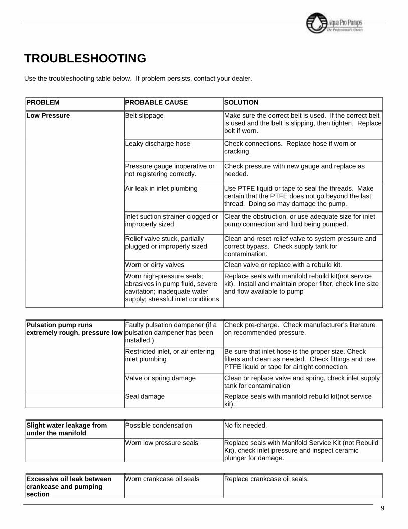
TROUBLESHOOTING
Use the troubleshooting table below. If problem persists, contact your dealer.
PROBLEM PROBABLE CAUSE SOLUTION
Low Pressure Belt slippage Make sure the correct belt is used. If the correct beltis used and the belt is slipping, then tighten. Replacebelt if worn.
Leaky discharge hose Check connections. Replace hose if worn orcracking.
Pressure gauge inoperative ornot registering correctly.
Check pressure with new gauge and replace asneeded.
Air leak in inlet plumbing Use PTFE liquid or tape to seal the threads. Makecertain that the PTFE does not go beyond the lastthread. Doing so may damage the pump.
Inlet suction strainer clogged orimproperly sized
Clear the obstruction, or use adequate size for inletpump connection and fluid being pumped.
Relief valve stuck, partiallyplugged or improperly sized
Clean and reset relief valve to system pressure andcorrect bypass. Check supply tank forcontamination.
Worn or dirty valves Clean valve or replace with a rebuild kit.
Worn high-pressure seals;abrasives in pump fluid, severecavitation; inadequate watersupply; stressful inlet conditions.
Replace seals with manifold rebuild kit(not servicekit). Install and maintain proper filter, check line sizeand flow available to pump
Pulsation pump runsextremely rough, pressure low
Faulty pulsation dampener (if apulsation dampener has beeninstalled.)
Check pre-charge. Check manufacturer’s literatureon recommended pressure.
Restricted inlet, or air enteringinlet plumbing
Be sure that inlet hose is the proper size. Checkfilters and clean as needed. Check fittings and usePTFE liquid or tape for airtight connection.
Valve or spring damage Clean or replace valve and spring, check inlet supplytank for contamination
Seal damage Replace seals with manifold rebuild kit(not servicekit).
Slight water leakage fromunder the manifold
Possible condensation No fix needed.
Worn low pressure seals Replace seals with Manifold Service Kit (not RebuildKit), check inlet pressure and inspect ceramicplunger for damage.
Excessive oil leak betweencrankcase and pumpingsection
Worn crankcase oil seals Replace crankcase oil seals.

708 SeriesHigh Pressure Titanium Positive Displacement Pump
10
PROBLEM PROBABLE CAUSE SOLUTION
Oil leaking in the area of thecrankshaft
Worn crankshaft oil seal Replace damaged oil seals. (Purchase crankcaserebuild kit, not service kit)
Bad bearing Replace bearing.
Cut or worn o-ring on bearingcase
Replace o-ring on bearing case.
Water in crankcase Humid air condensing into waterinside the crankcase
Change oil every three months or 300 hours
Worn or improperly installedcrankcase oil seals
Replace seals; follow proper installation procedure.
Excessive water leaking throughlow pressure seals
Replace seals with manifold rebuild kit(not servicekit).
Excessive play in the end ofthe crankshaft
Worn bearing Replace bearing.
Oil leaking in the rear portionof the crankcase
Damaged or improperly installedcrankcase cover, crankcasecover o-ring, drain-plug, or drain-plug o-ring.
Replace crankcase cover o-ring or drain-plug o-ring.
Loud knocking noise in pump Pulley loose on crankshaft Check key and tighten setscrew.
Restricted Inlet Clear obstruction or replace valve.
Worn bearing, connecting rod orcrankshaft.
Consult supplier for crankcase servicing.
Worn belts Replace belts.
Frequent or premature failureof the seals
Running pump dry NEVER RUN THE PUMP WITHOUT WATER.
Abrasive material in the fluidbeing pumped
Install proper filtration on pump inlet plumbing.
Excessive temperature ofpumped fluid (120 degrees Fmax.)
Reduce fluid inlet temperature to specifications.

11
PROBLEM PROBABLE CAUSE SOLUTION
Strong surging at the inlet and lowpressure
Foreign particles in the inlet ordischarge valve or worn inlet ordischarge valves
Check for smooth surfaces on inletand discharge valve seats. If signs ofwear or damage are present return tofactory for service.Check supply tank for contamination,regularly clean filter. Do not pumpabrasive fluid.
Restricted fluid flow Check the Inlet Conditions Checklist.

708 SeriesHigh Pressure Titanium Positive Displacement Pump
12
SERVICE
An authorized technician should perform all service.
Pump rebuild kits are available for seal overhauls. Contact your dealer for ordering information.
INTRODUCTION
All tasks should be performed in a clean environment, free from dust and debris. It is imperative that utmost cleanlinessbe maintained during the rebuild of your Aqua Pro Pump. The numbers following the parts are call out numbers. Theycorrespond to the parts on the drawings.
READ THE INSTRUCTIONS COMPLETELY BEFORE ATTEMPTING TO PERFORM ANY SERVICE.
Before assembling any parts, clean all parts to make free of oil, grease, dirt, and lint. Use a lint free cloth to wipe any partof the pump.
TOOLS NEEDED
Table 2: Tool List for Pump Service
3/16” Allen Wrench Phillips Head Screwdriver
1/4” Allen Wrench Pick
7/16" Socket/ Socket Wrench or Combination Wrench Snap Ring Pliers
9/16" Socket/ Socket Wrench or Combination Wrench Torque Wrench (220 in.-lb.)
1/2” Socket/ Socket Wrench or Combination Wrench Weep Ring Removal Tool (PN 91-3827)
3/4" Socket/ Socket Wrench or Combination Wrench Dead Blow Hammer
7/8" Socket/ Socket Wrench or Combination Wrench Flat Head Screwdriver
7/8" Combination Wrench
CAUTION
Ensure pump is disconnected from the motor or any driving devices. Service the pump in a clean, dirt-free environment.
NOTE
A light coating of Anti-Seize Lubricant (PN. 85-0094) should be applied on all threaded parts, unless otherwise stated.Only silicon grease (PN. 21-1122) should be used on all o-rings and seals. Use of any other type of grease may result ino-ring or seal failure.

13
DETACHING THE MANIFOLD FROM THE CRANKCASE
You will need these tools and parts to do the following:9/16” Socket/ Socket Wrench (for 708-5)1/2” Socket/ Socket Wrench (for 708-3)3/16” Allen Wrench (for 708-1)Dead Blow Hammer
Remove the two manifold bolts (58) with a 9/16” socket wrench for the 708-5, with a 1/2” socket wrench for the 708-3, orthe 4 socket head bolts with the 3/16” Allen wrench for the 708-1. Loosen the manifold assembly by lightly tapping off themanifold using the dead blow hammer, as seen in Fig. 2. Tap the manifold from both sides to apply even force to themanifold. Failing to do so can result in damage to the Ceramic Plungers. Set the manifold assembly aside in a clean workarea. If the manifold assembly locating dowel pins (53) fall out, reinsert them into the manifold alignment pin holes.
Fig. 2: Manifold Assembly Removal
ROUTINE SERVICE KITThe following are the part numbers for the 708 Series Routine Service Kits.708-1 Routine Service Kit (PN. 70-6181).708-3, 2.3 Routine Service Kit (PN. 70-6182).708-3, 3.5 Routine Service Kit (PN. 70-6183).708-5 Routine Service Kit (PN. 70-6184).
The Manifold Assembly must be detached from the crankcase to do the following service.
VALVE ASSEMBLY ROUTINE SERVICE
You will need these tools and parts to do the following:7/8" Socket Wrench or Combination WrenchPickSpring, Valve (45): PN. 70-6003Valve, Standard, 708 Series (44): PN. 70-6093 (For 708-1 & 708-3 2.3)Assembly, Valve, Heavy Duty, 708 Series (44): PN. 70-6104 (For 708-3 3.5 & 708-5)O-Ring, Valve Plug (46): PN. 70-6002Silicone Grease Lubricant: PN. 21-1122Anti-Seize Lubricant: PN. 85-0094Lint-Free Cloths

708 SeriesHigh Pressure Titanium Positive Displacement Pump
14
When the manifold assembly has been removed from the crankcase assembly, place the assembly on a clean worksurface. Remove all of the valve plug assemblies from the manifold assembly using a 7/8” socket wrench or combinationwrench. Remove the valve (44) from the assembly, followed by the valve spring (45). With the aide of a pick remove theo-ring (46) from the valve plug.
Clean and inspect all valve plugs (47) prior to reassembling. If there is a problem, contact your dealer. Once all valveplugs (47) are clean and dry, install new valve plug o-ring (46) onto valve plug (47). Install the valve spring (45) onto thevalve plug (47), it should now be attached to the plug. Press the valve (44) onto the valve spring (45). Complete valveassembly shown in Fig. 3.
Fig. 3: Valve Assembly(NOTE: There are two different valve plug designs)
Inspect the manifold (38) for debris or other fouling and clean if necessary. Inspect the valve seat surface in the manifold.If there is a problem contact your dealer. Reinstall all the valve plug assemblies with a 7/8" socket wrench or combinationwrench and tighten.
MANIFOLD SEAL ROUTINE SERVICE
You will need these tools and parts to do the following:Flat screw driverSeal, LP (45): PN. 70-6009Silicone Grease Lubricant: PN. 21-1122Lint-Free Cloths
NOTE
Valve plugs (47) will be reused.
A light coating of silicon grease (PN. 21-1122) should be used on all new o-rings and seals.Use of any other type of grease may result in o-ring or seal failure.
NOTE
A light coating of Anti-Seize Lubricant (PN. 85-0094) should be applied on all threaded parts, unless otherwise stated.
NOTE
Pump manifold assembly must be detached from the crankcase assembly to service the seals.

15
For manifold seal servicing purposes the manifold must be placed with the valve plugs sitting on a flat surface and theplunger bores facing upward. This will facilitate service technician access to the seals for removal and installation, asshown in Fig. 4.
Fig. 4: Orientation for Manifold Seal Servicing
With a flat screw driver remove the low-pressure seal (43). Ensure that the low-pressure seal spacer (39) was notaccidentally removed when the low-pressure seal was removed and press in the new low-pressure seal (43).
CRANKCASE SEAL ROUTINE SERVICE
Remove the seal retainer (29) and set aside. Remove the plunger retainer bolt (28) with a 7/16” wrench, set aside. Thereis no need to remove the plunger retainer washer (28) or plunger retainer o-rings (27) from the plunger retainer bolt (28).Remove the ceramic plunger (26). Remove the slinger (25) and the outer washer (6). With the aid of the pick remove theplunger rod oil seal (7) from the crankcase. Inspect the seal retainer washers (8) for damage, if none evident then reuse,if damage is evident consult the factory.
Insert new plunger rod oil seal (7) into crankcase making sure that the seal is fully seated, place outer washer (6) on seal.Place slinger (25) onto the plunger rod (9).
Slide ceramic plungers (26) onto plunger rod and insert the plunger retainer washer (28) into the plunger. Clean theplunger retaining bolt’s (29) threaded area. If they were removed replace the o-rings (27) onto the plunger retainer (29).Slide the plunger retaining washer (28) onto the plunger retainer (29).
A light coating of silicon grease (PN. 21-1122) should be used on all new o-rings and seals.Use of any other type of grease may result in o-ring or seal failure.
A light coating of silicon grease (PN. 21-1122) should be used on all new o-rings and seals.Use of any other type of grease may result in o-ring or seal failure.
NOTE
Examine the ceramic plungers (26) for cracks, heavy scoring, or unusual wear. If there is a problem, contact your dealer.

708 SeriesHigh Pressure Titanium Positive Displacement Pump
16
Fig. 5: Plunger Retaining Bolt Assembly
Apply Red Loctite # 262 to retainer bolt (29) threads. Reinstall the plunger retainer bolt (29) and torque to 100 in. lb. usinga 7/16” socket.
Apply Aqua Pro’s special Ceramic Lubricant (PN. 85-0087) to the ceramic plungers (26). Slide the seal retainer over theceramic plungers (26). Make sure that the flanged side is close proximity to the manifold assembly, and that hole isoriented downward ensuring that the seal retainer has adequate water drainage.
Fig. 6: Seal Retainer
Routine service is now complete.
NOTE
Be CAREFUL not to get the red loctite on any other components.

17
SERVICING THE CRANKCASE
The following are the procedures for servicing the crankcase assembly using the708-1 Crankcase Rebuild Kit (PN. 70-6113).708-3 Crankcase Rebuild Kit (PN. 70-6112).708-5 Crankcase Rebuild Kit (PN. 70-6107).
The manifold assembly must be detached from the crankcase to do the following service.
OIL DRAIN PLUG O-RING REPLACEMENT
You will need these tools and parts to do the following:7/8” Socket/ Socket WrenchPickO-Ring, Drain Plug (4): PN. 30-1286Anti-Seize Lubricant: PN. 85-0094Silicon Grease Lubricant: PN. 21-1122
Remove the oil drain plug with a 7/8” wrench and drain the crankcase oil. Clean the drain plug (5), remove the o-ring (4)with the aide of the pick if necessary. Replace with the new one supplied in the kit. Apply anti-seize lube to the threads ofthe drain plug (5) and reinstall.
PLUNGER ROD SEAL REPLACEMENT
You will need these tools and parts to do the following:7/16” Socket/ Socket WrenchTorque WrenchSeal, Oil, Plunger Rod (7): PN. 70-6018Washer, Plunger Retainer (27): PN. 70-6035O-Ring, Plunger Retainer (26): PN. 70-6012Slinger Barrier (24): PN. 70-6015Ceramic Lubricant: PN. 85-0087Silicone Grease Lubricant: PN. 21-1122Red Loctite # 262Lint-free Cloths
Remove the seal retainer (29) and set aside. Remove the plunger retainer bolt (28) with a 7/16” wrench, set aside.Remove the plunger retainer washer (28) and remove the ceramic plunger (26). Remove the slinger (25) and the outerwasher (6). With the aide of the pick remove the plunger rod oil seal (7) from the crankcase. Inspect the seal retainerwashers (8) for damage, if none evident then reuse, if damage is evident consult the factory.
Insert new plunger rod oil seal (7) into crankcase making sure that the seal is fully seated, place outer washer (6) on seal.Place slinger (25) onto the plunger rod (9).
NOTE
A light coating of silicon grease (PN. 21-1122) should be used on all new o-rings and seals.Use of any other type of grease may result in o-ring or seal failure.

708 SeriesHigh Pressure Titanium Positive Displacement Pump
18
Slide ceramic plungers (26) onto plunger rod and insert the plunger retainer washer (28) into the plunger. Clean theplunger retaining bolts (29). With the aide of a pick, remove the plunger retainer o-ring (27). Replace the o-ring (27) withthe new one supplied in the kit as shown in Fig. 6. Slide the plunger retaining washer (28) onto the plunger retainer (29).
Fig. 5: Plunger Retaining Bolt Assembly
Apply Red Loctite # 262 to retainer bolt (29) threads. Reinstall the plunger retainer bolt (29) and torque to 100 in. lb. usinga 7/16” socket.
Apply Aqua Pro’s special Ceramic Lubricant (PN. 85-0087) to the ceramic plungers (26). Slide the seal retainer over theceramic plungers (26). Make sure that the flanged side is close proximity to the manifold assembly, and that hole isoriented downward ensuring that the seal retainer has adequate water drainage.
Fig. 6: Seal Retainer
BEARING SIDE PLATE O-RING/SEAL REPLACEMENT
You will need these tools and parts to do the following:3/16" Allen WrenchPhilips Head Screw Driver
NOTE
Examine the ceramic plungers (26) for cracks, heavy scoring, or unusual wear. If there is a problem, contact your dealer.
NOTE
Be CAREFUL not to get the red loctite on any other components.

19
PickSeal, Oil, Crankshaft (18): PN. 70-6038 (708-1, 708-3) 70-6061 (708-5)O-Ring, Bearing Side Plate (15): PN. 70-6039O-Ring, Sight Glass (22): 70-6082Silicon Grease Lubricant: PN. 21-1122Anti-Seize Lubricant: PN. 85-0094
Remove the 4 socket head cap screws (19) with a 3/16” Allen Wrench from each of bearing side plate (16), (17), thisapplies to the 708-1, 708-3 3.5 GPM, and the 708-5 pumps. With the aide of a pick remove the o-rings from the grooves,remove the crankshaft oil seal (18) from the pulley side bearing cap (17).
For 708-3 2.3 GPM pumps with direct drive, uncouple the pump from the motor. Remove the 4 Philips head screws (36)holding the bell housing (34) to the pump. Now remove the bearing side plate (17), o-rings and seal can now be replaced.
Remove the sight glass retainer (24) from the bearing side plate (16). With the aide of a pick remove the sight glasso-ring (22). Replace o-ring with the one provided in the kit.
Press new crankshaft oil seal (18) into pulley side bearing cap (17), Install o-ring (15) in o-ring groove on the crankshaftbearing caps (16), (17) and reinstall caps on pump.
Install the 4 socket head cap screws (19) onto each of the bearing side plates and tighten with a 1/4” Allen Wrench. Thisapplies to the 708-1, 708-3 3.5 GPM, and the 708-5 pumps. For the 708-3 2.3 GPM pump, reinstall the bell housing (34)by installing the 4 Philips head screws (36).
CRANKCASE COVER O-RING REPLACEMENT
In this procedure you will replace the o-rings on the crankcase cover as provided in the rebuild kit.
You will need these tools and parts to do the following:3/16” Allen WrenchPhillips Head ScrewdriverPickSilicone Grease Lubricant: PN. 21-1122Red Loctite # 262Anti-Seize Lubricant: PN. 85-0094
CAUTION
Crankshaft oil seal is press fit at the factory, care is to be exercised during removal so damage does not occur to sealingsurface.
NOTE
A light coating of silicon grease (PN. 21-1122) should be used on all new o-rings and seals.Use of any other type of grease may result in o-ring or seal failure.
NOTE
A light coating of Anti-Seize Lubricant (PN. 85-0094) should be applied on all threaded parts, unless otherwise stated.
708 SeriesHigh Pressure Titanium Positive Displacement Pump
20
Unscrew the crankcase cover screws (19) with the 3/16” Allen wrench. With the aide of the pick remove the crankcasecover o-ring (20).
Install the new crankcase cover o-ring (20) provided with the rebuild kit.
Reinstall the crankcase cover and tighten the crankcase cover screws (19) with the 3/16” Allen wrench.
CRANKSHAFT BEARING, CONNECTING ROD-PISTON ASSEMBLY SERVICE
It is recommended that any service to the crankshaft bearings (16) or to the connecting rod-piston assembly be done bythe factory. Due to the high precision required only factory trained personnel are recommended for this service.Performing any maintenance other than rebuild and service kits voids the warranty if not performed by factory trainedpersonnel.
SERVICING THE MANIFOLD
The following are the procedures for servicing the crankcase assembly using the708-1 Manifold Rebuild Kit (PN. 70-6079).708-3 2.3 GPM Manifold Rebuild Kit (PN. 70-6110).708-3 3.5 GPM Manifold Rebuild Kit (PN. 70-6111).708-5 Manifold Rebuild Kit (PN. 70-6105). 8 GPM Pump Manufactured After Feb 2002708-5 Manifold Rebuild Kit (PN. 70-6108). 7 GPM Pump Manufactured Before Aug 2002
The manifold assembly must be detached from the crankcase to do the following service.
NOTE
A light coating of silicon grease (PN. 21-1122) should be used on all new o-rings and seals.Use of any other type of grease may result in o-ring or seal failure.
NOTE
A light coating of Anti-Seize Lubricant (PN. 85-0094) should be applied on all threaded parts, unless otherwise stated.

21
Fig. 7: Manifold Assembly
INLET/DISCHARGE ADAPTER O-RING REPLACEMENT 708-3 & 708-5
You will need these tools and parts to do the following:3/4” Socket/ Socket WrenchPickO-Ring, Discharge Plug Adapter (48): PN. 30-1286Silicone Grease Lubricant: PN. 21-1122Anti-Seize Lubricant: PN. 85-0094
Remove the Discharge/Plug (50) and (49) adapters from the manifold assembly with the 3/4” Socket/ Socket Wrench.With the aide of a pick remove the o-rings (48) from each of the adapters.
Install the new o-rings (48) provided with the kit onto each of the adapters.
Reinstall each of the adapters onto the manifold assembly, tighten adapter with 3/4” Socket/ Socket Wrench.
VALVE ASSEMBLY SERVICING
You will need these tools and parts to do the following:7/8" Socket Wrench or Combination WrenchPick
NOTE
A light coating of silicon grease (PN. 21-1122) should be used on all new o-rings and seals.Use of any other type of grease may result in o-ring or seal failure.
NOTE
A light coating of Anti-Seize Lubricant (PN. 85-0094) should be applied on all threaded parts, unless otherwise stated.

708 SeriesHigh Pressure Titanium Positive Displacement Pump
22
Spring, Valve (45): PN. 70-6003Valve (44): PN. 70-6093O-Ring, Valve Plug (46): PN. 70-6002Silicone Grease Lubricant: PN. 21-1122Anti-Seize Lubricant: PN. 85-0094Lint-Free Cloths
If manifold assembly has been removed from the crankcase assembly, place the assembly on a clean work surface.Remove all of the valve plug assemblies from the manifold assembly using a 7/8” socket wrench or combination wrench.Remove the valve (44) from the assembly, followed by the valve spring (45). With the aide of a pick remove the o-ring(46) from the valve plug.
Clean and inspect all valve plugs (47) prior to reassembly. If there is a problem, contact your dealer. Once all valve plugs(47) are clean and dry, install new valve plug o-ring (46) onto valve plug (47). Install the valve spring (45) onto the valveplug (47), it should now be attached to the plug. Press the valve (44) onto the valve spring (45). Complete valveassembly shown in Fig. 9.
Fig. 8: Valve Assembly(NOTE: There are two different valve plug designs)
Inspect the manifold (38) for debris or other fouling and clean if necessary. Inspect the valve seat surface in the manifold.If there is a problem contact your dealer. Reinstall all the valve plug assemblies with a 7/8" socket wrench or combinationwrench and tighten.
NOTE
Valves may be serviced while the manifold assembly is attached to the crankcase assembly.
NOTE
Valve plugs (47) will be reused.
A light coating of silicon grease (PN. 21-1122) should be used on all new o-rings and seals.Use of any other type of grease may result in o-ring or seal failure.
NOTE
A light coating of Anti-Seize Lubricant (PN. 85-0094) should be applied on all threaded parts, unless otherwise stated.

23
MANIFOLD SEAL SERVICING
You will need these tools and parts to do the following:Snap Ring PliersTool, Weep Ring Puller, 708 Series: PN. 91-3827Flat screw driverSeal, HP (40): PN. 70-0071Ring, Snap (42): PN. 70-6010Assembly, Weep Ring (41): PN. 70-3018Seal, LP (43): PN. 70-6009Silicone Grease Lubricant: PN. 21-1122Lint-Free Cloths
For manifold seal servicing purposes the manifold must be placed with the valve plugs sitting on a flat surface and theplunger bores facing upward. This will facilitate service technician access to the seals for removal and installation, asshown in Fig. 10.
Fig. 9: Orientation for Manifold Seal Servicing
With a flat screw driver remove the low-pressure seal (43). Manually remove the low-pressure seal spacer (39). With thesnap ring pliers remove the snap ring (42). Using the weep ring extracting tool remove the weep ring assembly (41) asshown in Fig. 11.
NOTE
Pump manifold assembly must be detached from the crankcase assembly to service the seals.
NOTE
Extraction of the rings is accomplished by inserting tool in relaxed state into the inner diameter of the rings, then tightenthe expansion bolt to grip the ring. Install the extraction stand and nut, tightening nut will extract to weep ring and isolatingring from manifold.

708 SeriesHigh Pressure Titanium Positive Displacement Pump
24
Fig. 10: Weep Ring Extraction
With a flat screwdriver remove the high-pressure seals (40). Manually remove the high-pressure seal spacer (40).
You must clean and inspect the following parts for re-use:Spacer, High-Pressure Seal (39): PN. 70-6016Spacer, Low-Pressure Seal (39): PN. 70-6016
Insert the high-pressure seal spacer (39) into the bore.
Insert the high-pressure seal (40) into the bore until the seal is fully seated on the high-pressure seal spacer (39).
Insert the weep ring (41) into the bore after the installation of the high-pressure seals (39). Install the snap ring (42) usingthe snap ring pliers.
Insert the low-pressure seal spacer (39) and press in the new low-pressure seal (43). The manifold seal servicing iscomplete.
ATTACHING THE MANIFOLD TO THE CRANKCASE
You will need these tools and parts to do the following:9/16” Socket/ Socket Wrench (for 708-5)1/2” Socket/ Socket Wrench (for 708-3)3/16” Allen Wrench (for 708-1)Dead Blow HammerDead Blow HammerManifold Bolt (58): PN. 70-6055 (for 708-5)Manifold Bolt (58): PN. 70-6008 (for 708-3)Manifold Screw (58): PN. 70-6046 (for 708-1)Ceramic Lubricant: PN. 85-0087Anti-Seize Lubricant: PN. 85-0094
NOTE
A light coating of silicon grease (PN. 21-1122) should be used on all new o-rings and seals.Use of any other type of grease may result in o-ring or seal failure.
NOTE
Ensure that the snap ring (42) is fully seated in the snap ring groove before continuing.

25
If a crankcase seal rebuild was not performed at this time then ensure that the dowel locating pins (53) are pressed intotheir corresponding hole. Ensure that ceramic lubricant is applied to the ceramic plunger assemblies and that the sealretainers are installed with the flange located away from the crankcase assembly.
Align manifold assembly to crankcase assembly and tighten the two manifold bolts (58) with a 9/16” socket wrench for the708-5, with a 1/2” socket wrench for the 708-3, or the 4 socket head bolts with the 3/16” Allen wrench for the 708-1.
NOTE
A light coating of Anti-Seize Lubricant (PN. 85-0094) should be applied on all threaded parts, unless otherwise stated.

708 SeriesHigh Pressure Titanium Positive Displacement Pump
26

éðèóï ÜÎßÉ×ÒÙÍ


éðèóí ÜÎßÉ×ÒÙÍ


éðèóë ÜÎßÉ×ÒÙÍ


ß«¿Ð®±rÍ»¿É¿¬»®ÎÑÓ»³¾®¿²»
߯«¿Ð®±r
®»ª»®» ±³±· ³»³¾®¿²»¼»´·ª»® ¸·¹¸ ¿´¬ ®»¶»½¬·±² ©¸·´»³¿·²¬¿·²·²¹ ¸·¹¸ °®±¼«½¬·±²®¿¬» ¬± ±¾¬¿·² ¬¸» »²»®¹§
±°»®¿¬±®ò
Þ§ »´»½¬·²¹ ¬¸» ¸·¹¸»¬ ¹®¿¼» ±º³¿¬»®·¿´ ¿²¼ ¬¸±®±«¹¸´§ ¬»¬·²¹
°»®º±®³¿²½»ô п®µ»® · ¿¾´»
°®±¼«½¬ò
߯«¿ Ю±r ³»³¾®¿²» ¿®»¼»·¹²»¼ º±® «» ·² п®µ»®°®»«®» ª»»´ ¸±«·²¹ ¿ ©»´´¿ ±¬¸»® ¾®¿²¼ ¸±«·²¹ò
ݱ²¬¿½¬ ײº±®³¿¬·±²æ
îêíð Ûò Û´ Ю»·¼·± ͬ®»»¬
Ý¿®±²ô Ýß çðèïð
°¸±²» øíïð÷ êðèóëêðð
º¿¨ øíïð÷ êðèóëêçî

� Ó¿¨·³«³ Ñ°»®¿¬·²¹ Ю»«®»æ ïððð °·
� Ó¿¨·³«³ Ñ°»®¿¬·²¹ Ì»³°»®¿¬«®»æ ïïípÚ øìëpÝ÷
� Ó¿¨·³«³ Ú»»¼ Ì«®¾·¼·¬§æï ÒÌË
� Ú®»» ݸ´±®·²» ̱´»®¿²½»æð ÐÐÓ
� Ó¿¨·³«³ Ú»»¼ Í·´¬ Ü»²·¬§ ײ¼»¨æ ÍÜ× ë
� °Ø ο²¹»æݱ²¬·²«±« Ñ°»®¿¬·±²æ ìóïï͸±®¬ó¬»®³ º±® Ý´»¿²·²¹æøíð ³·²«¬» ¼«®¿¬·±²÷ îòëóïï
ß«¿Ð®±r
Í»¿É¿¬»®ÎÑ
Ó»³¾®¿²»
Ò±¬»æ
λ½±³³»²¼»¼
Ñ°»®¿¬·²¹ Ô·³·¬æ
� Õ»»° »´»³»²¬ ³±·¬ ¿¬ ¿´´¬·³»
� ¬©± ¸±«® ±º ±°»®¿¬·±² ¸±«´¼¾» ¼·½¿®¼»¼
� ̱ °®»ª»²¬ ¾·±´±¹·½¿´ ¹®±©¬¸¼«®·²¹ ¬±®¿¹»ô ¸·°°·²¹ô±® §¬»³ ¸«¬¼±©² ·¬ ·®»½±³³»²¼»¼ ¬¸¿¬ »´»³»²¬¾» ·³³»®»¼ ·² ¿ °®±¬»½¬·ª»
±´«¬·±² º±® ´±²¹ ±® ¸±®¬ ¬»®³¬±®¿¹» ¸±«´¼ ½±²¬¿·² ïòð°»®½»²¬ ø¾§ ©»·¹¸¬÷ ±¼·«³
ÊÓÌ °ñ² èëóðïðíô èëóððíèôèëóððìì ±® èëóððìç÷
� ͬ¿²¼¿®¼·¦»¼ ¬»¬ ½±²¼·¬·±²¿®» íîôððð °°³ Ò¿Ý´ ¿¬ éépÚ øîëp Ý÷ô ©·¬¸ èðð °· º»»¼òЮ±¼«½¬·±² ®¿¬» º±® ·²¼·ª·¼«¿´»´»³»²¬ ³¿§ ª¿®§ õñó îðû ¿²¼®»¶»½¬·±² ³¿§ ª¿®§ õñó ðòìû
©¿¬»®³¿µ»®ò
Ю·²¬ λ±®¼»® Ò«³¾»® éèçé λªóÏ ðëóíðóîðïé
Ò±³·²¿´
Í·¦»
îëïç
îëïç
îëïç
îëíè
îëíè
ìðìð
êðìð
èðìð
Ю±¼«½¬ Ú´±©
ÙÐÜ ³íñ¼¿§
îîð ó ðòèí
ïëð ó ðòëé
ïðë ó ðòìð
ëëð ó îòðè
îïð ó ðòèð
ïîðð ó ìòëì
îëðð ó çòìé
éîëðóîéòíê
̧°·½¿´ Í¿´¬
붻½¬·±² û
ççòì
ççòð
ççòð
ççòì
ççòð
ççòì
ççòì
ççòì
ÊÓÌ
ﮬ Ò±ò
ííóîëïç
ííóíððð öö
ííóíððïöö
ííóðîíè
ííóíððîöö
ííóðììð
ííóððíê
ííóðèìð
Ü·³»²·±²
·²½¸»ñ½³
ßö
ïçñìè
ïçñìè
ïçñìè
íèñçêòë
íèñçêòë
ìðñïðïòê
ìðñïðïòê
ìðñïðïòê
Þ
ïòïñîòè
ïòïñîòè
ïòïñîòè
ïòïñîòè
ïòïñîòè
ïòðñîòë
ïòîéñíòî
ð
Ý
ðòéëñïòç
ðòéëñïòç
ðòéëñïòç
ðòéëñïòç
ðòéëñïòç
ðòéëñïòç
ïòëñíòè
ïòïîëñîç
Ü
îòìñêòï
îòìñêòï
îòìñêòï
îòìñêòï
îòìñêòï
íòçêñïðòï
ëòçèñïëòî
éòçñîðï

ο½±®Ê·¿¹»Ó¿®·²»Îѳ»³¾®¿²»°®»«®»ª»»º»¿¬«®»²±²ó³»¬¿·½©»¬¬»¼«®º¿½»º±®»½»»²¬½±®®±·±²®»·¬¿²½»òÍ·³°»»²¼°«¹¼»·¹²¿±©
«·½µ®»³±ª¿º±®»»³»²¬»®ª·½·²¹ò׺¬»·¦»§±«®»«·®»·²±¬±©²°»¿»½±²¬¿½¬«º±®½«¬±³¾«·¼ò
Ю»«®» Ê»»´
ß»³¾´·»
ݱ²¬¿½¬ ײº±®³¿¬·±²æ
ο½±® Ü·ª··±²ñÊ·´´¿¹» Ó¿®·²» Ì»½ò
îêíð Ûò Û´ Ю»·¼·± ͬ®»»¬
Ý¿®±²ô Ýß çðèïð
°¸±²» íïð ëïê ççïï
º¿¨ íïð ëíè íðìè
®¿½±®à°¿®µ»®ò½±³
©©©òª·´´¿¹»³¿®·²»ò½±³
©©©ò°¿®µ»®ò½±³ñ®¿½±®
Õ»§ Ú»¿¬«®»æ
Ñ°»®¿¬·²¹Ð®»«®»æïððð°·ñê辿®
ݱ¿®æêðêïÌóêб©¼»®½±¿¬»¼¿«³·²«³
Û²¼Î·²¹æêðêï Ìóê ß²±¼·¦»¼ ¿«³·²«³ ±² îòë� ¿²¼ ì� ·¦»ÍÍíïê ±² ê� ·¦»Ú¿¬»²»®æÍÍíïê
Ú±® Í»¿©¿¬»® Û´»³»²¬

Ü»½®·°¬·±²
Ê»»´ ß»³¾´§öö
Ю±¼«½¬ Ñó®·²¹
Û²¼ д«¹ Ñó®·²¹
Û²¼ д«¹
Û²¼ η²¹
Ý¿°½®»©
͸»´´ ɸ·¬»
Ù®¿§
׬»³
ï
î
í
ì
ë
ê
é
Ï«¿²¬·¬§ °»®
ß»³¾´§
ì
î
î
î
ööö
ï
ï
îòë� ¨ ïç�
íîóîëïç
íîóîïïê
íîóîîîè
íîóîëïíö
íîóìðïí
èêóðïðê
íîóððîë
íîóððçè
ëñî
îòë� ¨ íè�
íîóîëíéö
íîóîïïê
íîóîîîè
íîóîëïíö
íîóìðïí
èêóðïðê
íîóððîê
íîóððçç
éñí
ì� ¨ ìð�
íîóðììì
íîóîïïê
íîóìíìî
íîóìðïî
íîóìðïì
èêóðïîí
д»¿» Ý¿´´
íîóìððï
îîñïð
ê� ¨ ìð�
íîóêðìð
íîóîîîç
íîóðêìð
íîóêðïî
íîóððçê
èêóðïíê
д»¿» Ý¿´´
íîóðððï
ìëñîðÉ»·¹¸¬ ø´¾ñµ¹÷
Û²¼ Ы¹ íîóîëïé · ¿± ¿ª¿·¿¾» º±® îòë�
º»»¼ñ®»¶»½¬°±®¬«»¼±²±³»ÊÓÌÐÉ©¿¬»®³¿µ»®òË»±º½±¿®»¬®»¿¼»²¼°«¹½¿²¹»¬»ª»»¿»³¾§°ñ²¬±íîóîëíè
Ý¿°½®»©æÑ®¼»® ê °»® »²¼ °«¹ ±² îòë� ·¦»Ñ®¼»® è °»® »²¼ °«¹ ±² ì� ·¦»Ñ®¼»® ïð °»® »² °«¹ ±² ê� ·¦»
Ю»«®» Ê»»´
ß»³¾´·»
Ú±® Í»¿©¿¬»® Û´»³»²¬
ﮬ Ò«³¾»®æ
Ю·²¬ λ±®¼»® Ò«³¾»® éèçè λªóß ïîóïðóîðïî
̱ ³¿·²¬¿·² °»¿µ °»®º±®³¿²½» ¿´©¿§ «» ¹»²«·²» п®µ»®óο½±®ñÊ·´´¿¹» Ó¿®·²» Ì»½ò ®»°´¿½»³»²¬ °¿®¬ò
Ó»³¾®¿²»²±¬·²½«¼»¼òÚ±®¿°°·½¿¾»³»³¾®¿²»»»³»²¬»»¾«»¬·²Ò±òéèçéøß«¿Ð®±ÎÑÓ»³¾®¿²»÷

©¿¬»®³¿µ»®·²¼«¬®§¿²¼¿®»«°»®·±®¬±©±«²¼±®°±§°«²½¿®¬®·¼¹»¬±
½¿®¬®·¼¹»·¦»¼±©²ò
ߪ¿·¿¾»·²¿©·¼»¿®®¿²¹»±º·¦»¿²¼³·½®±²®¿²¹»¬±»²«®»¬¿¬»ª»®§
²±¬±©²°»¿»½±²¬¿½¬«©·¬¬»¼·³»²·±²®»«·®»¼ò
д»¿¬»¼ Ú·´¬»® ¿²¼Ú·´¬»® Ý¿®¬®·¼¹» Õ·¬
Í·²¹»«»Ý»¿²·²¹¿²¼Ð®»»®ª¿¬·ª»
³¿·²¬»²¿²½»ò
Ý¿®¬®·¼¹»Õ·¬»·³·²¿¬»¬»¬®±«¾»¿²¼³»±º³»¿«®·²¹°±©¼»®»¼½»³·½¿¿²¼»²«®·²¹½±®®»½¬
ìòë� ïð� ±«·²¹ ¿²¼ ½±²¬¿·² ¬» ½±®®»½¬¿³±«²¬±º½»³·½¿º±®¿·²¹»«»ò
ݱ²¬¿½¬ ײº±®³¿¬·±²æ
îêíð Ûò Û´ Ю»·¼·± ͬ®»»¬
Ý¿®±²ô Ýß çðèïð
°¸±²» øíïð÷ êðèóëêðð
º¿¨ øíïð÷ êðèóëêçî
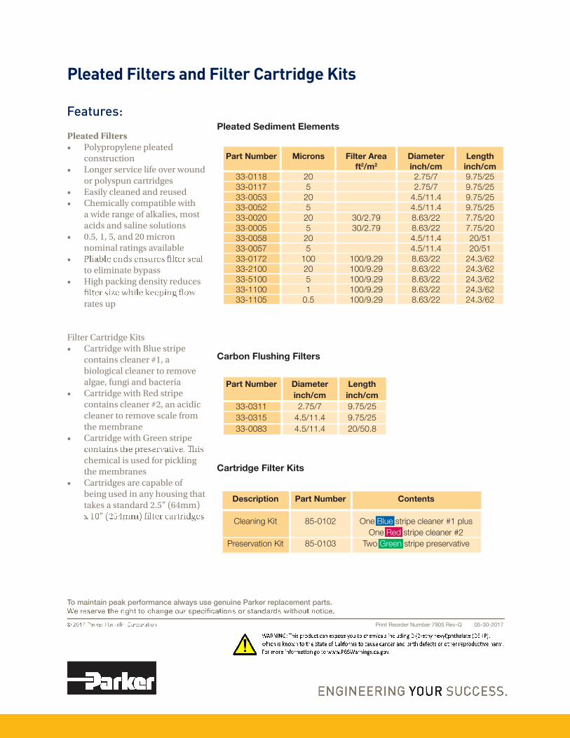
д»¿¬»¼ Ú·´¬»®
� б§°®±°§»²» °»¿¬»¼ ½±²¬®«½¬·±²
� Ô±²¹»® »®ª·½» ·º» ±ª»® ©±«²¼ ±®°±§°«²½¿®¬®·¼¹»
� Û¿·§ ½»¿²»¼ ¿²¼ ®»«»¼� Ý»³·½¿§ ½±³°¿¬·¾» ©·¬
¿©·¼»®¿²¹»±º¿µ¿·»ô³±¬¿½·¼¿²¼¿·²»±«¬·±²
� ðòëô ïô ëô ¿²¼ îð ³·½®±² ²±³·²¿®¿¬·²¹¿ª¿·¿¾»
� ¬±»·³·²¿¬»¾§°¿
� Ø·¹ °¿½µ·²¹ ¼»²·¬§ ®»¼«½»
®¿¬»«°
Ú·¬»®Ý¿®¬®·¼¹»Õ·¬� Ý¿®¬®·¼¹» ©·¬ Þ«» ¬®·°»
½±²¬¿·²½»¿²»®ýïô¿¾·±±¹·½¿½»¿²»®¬±®»³±ª»¿¹¿»ôº«²¹·¿²¼¾¿½¬»®·¿
� Ý¿®¬®·¼¹» ©·¬ λ¼ ¬®·°» ½±²¬¿·²½»¿²»®ýîô¿²¿½·¼·½½»¿²»®¬±®»³±ª»½¿»º®±³¬»³»³¾®¿²»
� Ý¿®¬®·¼¹» ©·¬ Ù®»»² ¬®·°»
½»³·½¿·«»¼º±®°·½µ·²¹¬»³»³¾®¿²»
� Ý¿®¬®·¼¹» ¿®» ½¿°¿¾» ±º ¾»·²¹«»¼·²¿²§±«·²¹¬¿¬¬¿µ» ¿ ¬¿²¼¿®¼ îòë� øêì³³÷
д»¿¬»¼ Ú·´¬»® ¿²¼ Ú·´¬»® Ý¿®¬®·¼¹» Õ·¬
Ú»¿¬«®»æ
Ý¿®¾±² Ú´«¸·²¹ Ú·´¬»®
Ý¿®¬®·¼¹» Ú·´¬»® Õ·¬
д»¿¬»¼ Í»¼·³»²¬ Û´»³»²¬
ﮬ Ò«³¾»®
ííóðïïè
ííóðïïé
ííóððëí
ííóððëî
ííóððîð
ííóðððë
ííóððëè
ííóððëé
ííóðïéî
ííóîïðð
ííóëïðð
ííóïïðð
ííóïïðë
Ó·½®±²
îð
ë
îð
ë
îð
ë
îð
ë
ïðð
îð
ë
ï
ðòë
Ú·´¬»® ß®»¿
º¬îñ³î
íðñîòéç
íðñîòéç
ïððñçòîç
ïððñçòîç
ïððñçòîç
ïððñçòîç
ïððñçòîç
Ü·¿³»¬»®
·²½¸ñ½³
îòéëñé
îòéëñé
ìòëñïïòì
ìòëñïïòì
èòêíñîî
èòêíñîî
ìòëñïïòì
ìòëñïïòì
èòêíñîî
èòêíñîî
èòêíñîî
èòêíñîî
èòêíñîî
Ô»²¹¬¸
·²½¸ñ½³
çòéëñîë
çòéëñîë
çòéëñîë
çòéëñîë
éòéëñîð
éòéëñîð
îðñëï
îðñëï
îìòíñêî
îìòíñêî
îìòíñêî
îìòíñêî
îìòíñêî
Ü·¿³»¬»®
·²½¸ñ½³
îòéëñé
ìòëñïïòì
ìòëñïïòì
Ô»²¹¬¸
·²½¸ñ½³
çòéëñîë
çòéëñîë
îðñëðòè
ﮬ Ò«³¾»®
ííóðíïï
ííóðíïë
ííóððèí
ﮬ Ò«³¾»®
èëóðïðî
èëóðïðí
Ü»½®·°¬·±²
Ý´»¿²·²¹ Õ·¬
Ю»»®ª¿¬·±² Õ·¬
ݱ²¬»²¬
Ѳ» Þ´«» ¬®·°» ½´»¿²»® ýï °´«
Ѳ» λ¼ ¬®·°» ½´»¿²»® ýî
Ì©± Ù®»»² ¬®·°» °®»»®ª¿¬·ª»
Ю·²¬ λ±®¼»® Ò«³¾»® éçðë λªóÏ ðëóíðóîðïé
̱ ³¿·²¬¿·² °»¿µ °»®º±®³¿²½» ¿´©¿§ «» ¹»²«·²» п®µ»® ®»°´¿½»³»²¬ °¿®¬ò


