
The industry’s first industrial drive control SoC
supporting digital and analog position sensors
C2000™ DesignDRIVE Position Manager technology solves interfacing
challenges with position sensors in industrial servo and AC inverter drives
Brian Fortman, C2000™ Marketing
Industrial Drives and Automation Position Encoder Interface Circuits DesignDRIVE Kit (TMDXIDDK377D)

Agenda
• Top-level overview of DesignDRIVE Position Manager and its benefits
• Analog position sensor interface solutions
• Absolute encoder master solutions
• Getting started
2

www.ti.com/C2000Drives
3
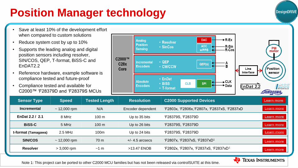
Sensor Type Speed Tested Length Resolution C2000 Supported Devices
Incremental ~ 12,000 rpm N/A Encoder dependent ‘F2803x, ‘F2806x,‘F2807x, ‘F2837xS, ‘F2837xD
EnDat 2.2 / 2.1 8 MHz 100 m Up to 35 bits ‘F28379S, ‘F28379D
BiSS-C 5 MHz 100 m Up to 26 bits ‘F28379S, ‘F28379D
t-format (Tamagawa) 2.5 MHz 100m Up to 24 bits ‘F28379S, ‘F28379D
SIN/COS ~ 12,000 rpm 70 m +/- 4.5 arcsecs ‘F2807x, ‘F2837xS, ‘F2837xD1
Resolver > 3,000 rpm ~1 m >13.47 ENOB ‘F2802x, ‘F2807x, ‘F2837xS, ‘F2837xD
1
Position Manager technology
• Save at least 10% of the development effort
when compared to custom solutions
• Reduce system cost by up to 10%
• Supports the leading analog and digital
position sensors including resolver,
SIN/COS, QEP, T-format, BiSS-C and
EnDAT2.2
• Reference hardware, example software is
compliance tested and future-proof
• Compliance tested and available for
C2000™ ‘F28379D and ‘F28379S MCUs
4
Note 1: This project can be ported to other C2000 MCU families but has not been released via controlSUITE at this time.

C2000™ Delfino™ F28379 MCUs and DesignDRIVE Position Manager technology
5
Solve Conformance
Challenges
Simplify the
System
Save Development
Time
Alleviate months of work
proving sensor interface
compatibility
Reduces system cost by 10%
while improving system
performance
Eliminates up to 10% of the
development engineering
effort
The industry’s first industrial drive control system-on-chip
to support digital and analog position sensors
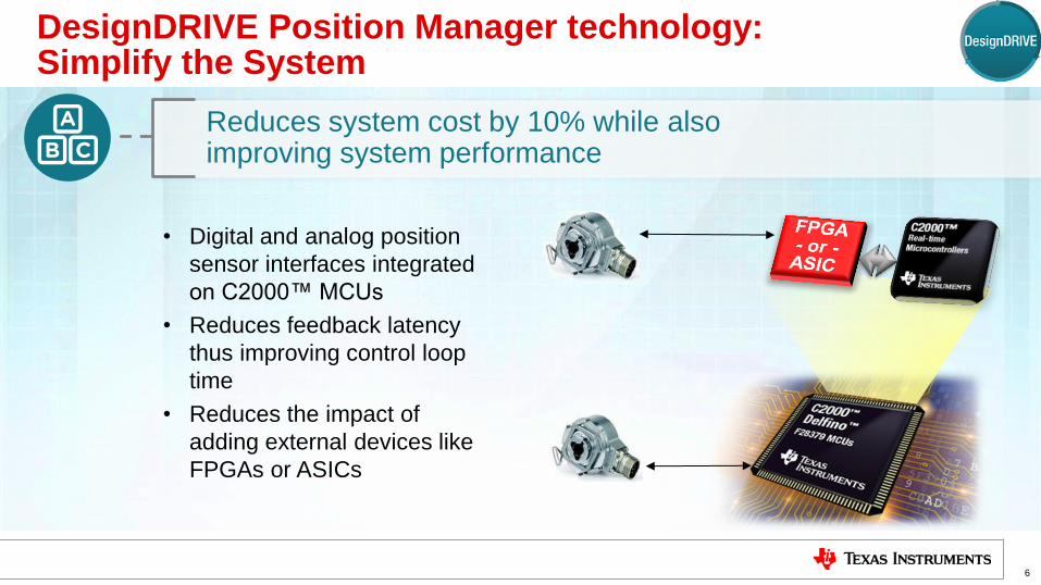
DesignDRIVE Position Manager technology: Simplify the System
6
• Digital and analog position
sensor interfaces integrated
on C2000™ MCUs
• Reduces feedback latency
thus improving control loop
time
• Reduces the impact of
adding external devices like
FPGAs or ASICs
Reduces system cost by 10% while also improving system performance

DesignDRIVE Position Manager technology: Save Development Time
7
• Performance-tuned
software
• Reference hardware &
software
• API, line interface and
power supply reference
designs from TI
A complete solution from TI’s
C2000™ MCU team
High-Level Driver
Low-Level Driver
Hardware
Silicon
Existing Custom
EnDat_HLD
Custom
Custom
FPGA Gates
Example
Project
PM_endat22
API / Library
IDDK
Reference
C2000 EnDat
Peripheral
SPI+GPIO+CLB
Traditional
FPGA
Approach
With C2000
Position
Manager
Eliminates up to 10% of the development engineering effort
EnDat 2.2 Solution Example: Stackup vs. FPGA
TIDA-00179
TIDM-SERVODRIVE

DesignDRIVE Position Manager technology: Solve Conformance Challenges
8
Gives developers peace-of-mind regarding sensor interface compatibility
• Compliance testing
performed by TI for
EnDat 2.2, BiSS-C and
T-format
• DesignDRIVE
Development Kit (IDDK)
testing reference
• Roadmap support for
more protocol standards,
future revisions
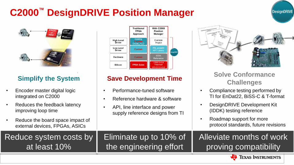
C2000™ DesignDRIVE Position Manager
9
Solve Conformance
Challenges Simplify the System Save Development Time
• Encoder master digital logic
integrated on C2000
• Reduces the feedback latency
improving loop time
• Reduce the board space impact of
external devices, FPGAs, ASICs
• Compliance testing performed by
TI for EnDat22, BiSS-C & T-format
• DesignDRIVE Development Kit
(IDDK) testing reference
• Roadmap support for more
protocol standards, future revisions
• Performance-tuned software
• Reference hardware & software
• API, line interface and power
supply reference designs from TI
Reduce system costs by
at least 10%
Eliminate up to 10% of
the engineering effort
Alleviate months of work
proving compatibility
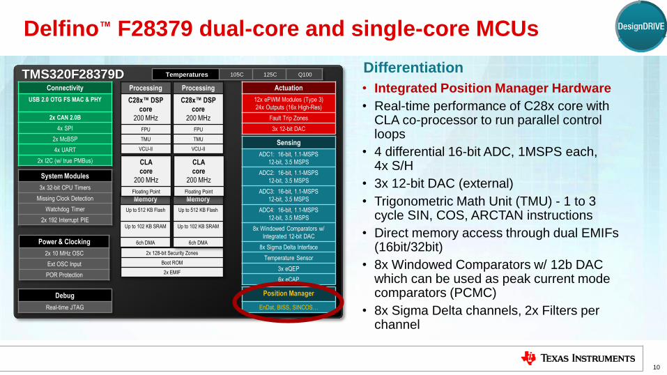
Delfino™ F28379 dual-core and single-core MCUs
10
• Integrated Position Manager Hardware
• Real-time performance of C28x core with CLA co-processor to run parallel control loops
• 4 differential 16-bit ADC, 1MSPS each, 4x S/H
• 3x 12-bit DAC (external)
• Trigonometric Math Unit (TMU) - 1 to 3 cycle SIN, COS, ARCTAN instructions
• Direct memory access through dual EMIFs (16bit/32bit)
• 8x Windowed Comparators w/ 12b DAC which can be used as peak current mode comparators (PCMC)
• 8x Sigma Delta channels, 2x Filters per channel
Differentiation
Sampling
TMS320F28379D
Memory
Up to 512 KB Flash
Up to 102 KB SRAM
6ch DMA
CLA
core
200 MHz
Floating Point
Temperatures 105C 125C Q100
Processing
C28x™ DSP
core
200 MHz
FPU
TMU
VCU-II
2x 128-bit Security Zones
Boot ROM
2x EMIF
Memory
Up to 512 KB Flash
Up to 102 KB SRAM
6ch DMA
CLA
core
200 MHz
Floating Point
Processing
C28x™ DSP
core
200 MHz
FPU
TMU
VCU-II
Actuation
12x ePWM Modules (Type 3)
24x Outputs (16x High-Res)
Fault Trip Zones
3x 12-bit DAC
Power & Clocking
2x 10 MHz OSC
Ext OSC Input
POR Protection
Debug
Real-time JTAG
Sensing
ADC1: 16-bit, 1.1-MSPS
12-bit, 3.5 MSPS
ADC2: 16-bit, 1.1-MSPS
12-bit, 3.5 MSPS
ADC3: 16-bit, 1.1-MSPS
12-bit, 3.5 MSPS
ADC4: 16-bit, 1.1-MSPS
12-bit, 3.5 MSPS
8x Windowed Comparators w/
Integrated 12-bit DAC
8x Sigma Delta Interface
Temperature Sensor
3x eQEP
6x eCAP
System Modules
3x 32-bit CPU Timers
Missing Clock Detection
Watchdog Timer
2x 192 Interrupt PIE
Position Manager
EnDat, BISS, SINCOS…
Connectivity
USB 2.0 OTG FS MAC & PHY
2x CAN 2.0B
4x SPI
2x McBSP
4x UART
2x I2C (w/ true PMBus)

Integrated Position Manager
• First MCU with both digital and analog position sensor support
• Released on ‘F28379D/S today
• Integrated sensor master/controller with control loop processor
• Flexible, multi-protocol support
• Software stackup and example use application
• Reference hardware design and compatibility tested
“Standalone” Position Manager Add-On
• Works independent to control loop processor
• Leverages same core Position Manager library
• Position Manager performance and testing
• Simple SPI (or other) interface to
customer’s controller
• Stay tuned for further cost-optimized add-on
versions
11
C2000 DesignDRIVE Position Manager Implementation Options
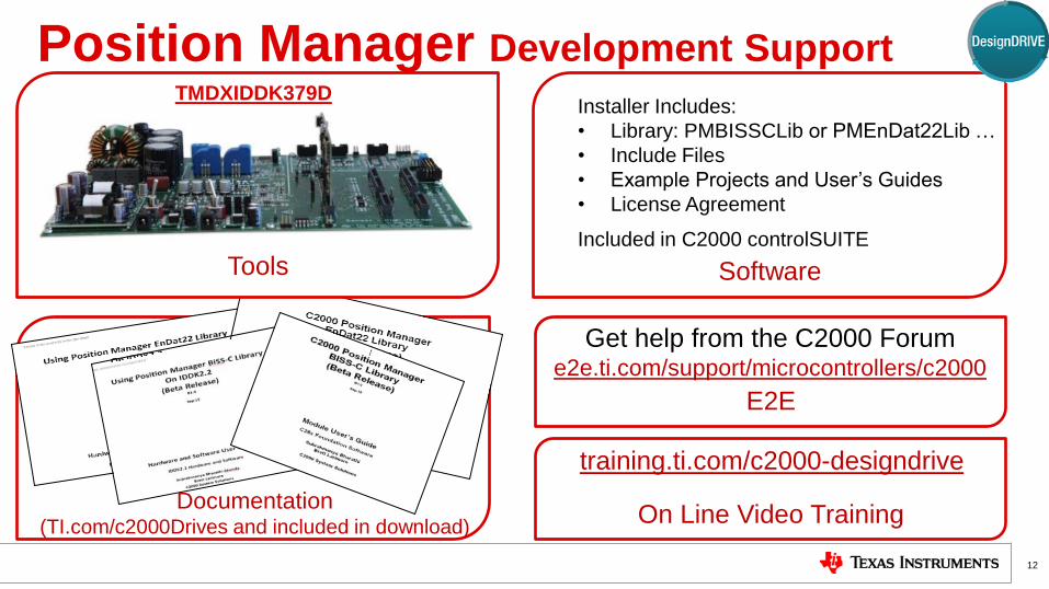
Tools
E2E
Position Manager Development Support
12
TMDXIDDK379D
Get help from the C2000 Forum e2e.ti.com/support/microcontrollers/c2000
Software
Included in C2000 controlSUITE
Installer Includes:
• Library: PMBISSCLib or PMEnDat22Lib …
• Include Files
• Example Projects and User’s Guides
• License Agreement
On Line Video Training
training.ti.com/c2000-designdrive
Documentation (TI.com/c2000Drives and included in download)

TI Information – Selective Disclosure
Position Manager Solutions
13
Sensor Type Speed Tested Length Resolution C2000 Supported Devices
Incremental ~ 12,000 rpm N/A Encoder dependent ‘F2803x, ‘F2806x,‘F2807x, ‘F2837xS, ‘F2837xD
CW/CCW Any device with eQEP – please see lit # SPRABX2
“CW/CCW Support on the C2000 eQEP Module”
EnDat 2.2 / 2.1 8 MHz 100 m Up to 35 bits ‘F28379S, ‘F28379D
BiSS-C 5 MHz 100 m Up to 26 bits ‘F28379S, ‘F28379D
t-format (Tamagawa) 2.5 MHz 100m Up to 24 bits ‘F28379S, ‘F28379D
SIN/COS ~ 12,000 rpm 70 m +/- 4.5 arcsecs ‘F2807x, ‘F2837xS, ‘F2837xD1
Resolver > 3,000 rpm ~1 m >13.47 ENOB ‘F2802x, ‘F2807x, ‘F2837xS, ‘F2837xD
1

TI Information – Selective Disclosure
DesignDRIVE Position Manager SIN/COS
An overview of the C2000 SIN/COS solution
14
Sensor Type Speed Tested Length Resolution C2000 Supported Devices
Incremental ~ 12,000 rpm N/A Encoder dependent ‘F2803x, ‘F2806x,‘F2807x, ‘F2837xS, ‘F2837xD
CW/CCW Any device with eQEP – please see lit # SPRABX2
“CW/CCW Support on the C2000 eQEP Module”
EnDat 2.2 / 2.1 8 MHz 100 m Up to 35 bits ‘F28379S, ‘F28379D
BiSS-C 5 MHz 100 m Up to 26 bits ‘F28379S, ‘F28379D
t-format (Tamagawa) 2.5 MHz 100m Up to 24 bits ‘F28379S, ‘F28379D
SIN/COS ~ 12,000 rpm 70 m +/- 4.5 arcsecs ‘F2807x, ‘F2837xS, ‘F2837xD1
Resolver > 3,000 rpm ~1 m >13.47 ENOB ‘F2802x, ‘F2807x, ‘F2837xS, ‘F2837xD
1

DesignDRIVE Position Manager SIN/COS technology: Simplify the System
15
Reduce system cost by AND improve system performance
Features Benefits
• Integrated MCU solution for interface to SIN/COS
transducers
• Lowers system cost - no additional external
sensing circuitry (sensor power supply and diff
amps are still required)
• Potentially lowers sensing latency (depending
on existing architecture)
• Supports high shaft speeds as well as high
resolution at low speeds - 3 operating modes
based on shaft speed
• Optimum precision across a wide speed range
• Error detection • Robust data integrity
• Continuous calibration (at low speed) • Automatic correction of drift and offset errors
• Delivers position and speed information • Tunable for each application
• Tuned for position control applications
(information obtained every control cycle) • Built for position and timing performance
• Packaged library module • Easy to integrate and use
• Available now! • Begin development today!

CMP
INDEX
ADC-B
ADC-A
C28x™
Core(s)
How does the DesignDRIVE SIN/COS solution work?
CMP
CMP Angle = arctan(A/B)
QEP
Speed = PulseCount
C2000™ MCU SINCOS User’s Guide:
TI.com/lit/SPRUI54

Position Manager SIN/COS Solution
System Block Diagram
• SinCos solution supported on C2000 MCUs
with dual ADCs, comparators and QEP
• Software project is based on ‘F2837x
• Requires buffer interfaces and transducer
power supply circuits outside MCU
• Interface circuits included on the
DesignDRIVE Development Kit – IDDK
SIN/COS Receiver
• Simultaneously sampling ADC
• Converts quadrature sinusoidal signals – low speeds
• Comparators
• Convert sinusoids to pulses – high speeds
• Quadrature Encoder Pulse Module (QEP)
• Counts high speed pulses and indicates direction
• C28x CPU
• Filtering, Calibration, Offset Correction, Gain Control
• Fine angle calculation
Check out TI Designs
TIDA-00176
TIDM-SERVODRIVE
TMS320F2837x Motor SinCos position encoder
Connector
CableEncoderPower Supply
A
B
I
F2837x
An
alo
g Su
b-S
yste
m
PMSinCosLibrary
Signal Conditioning Board

SINCOS Commands Supported
18
Command Description
PM_sincos_calcAngle Computes the mechanical shaft angle in scaler per-unit
PM_sincos_updateCalData Calculates the gain and offset calibration coefficients
and updates active values
PM_sincos_initLib
Sets the elements of the specified SINCOS data
structure to their default values. The function clears all
data from both input filters, and initializes the selected
QEP peripheral.
PM_sincos_reset Resets the dynamic SINCOS variables to default
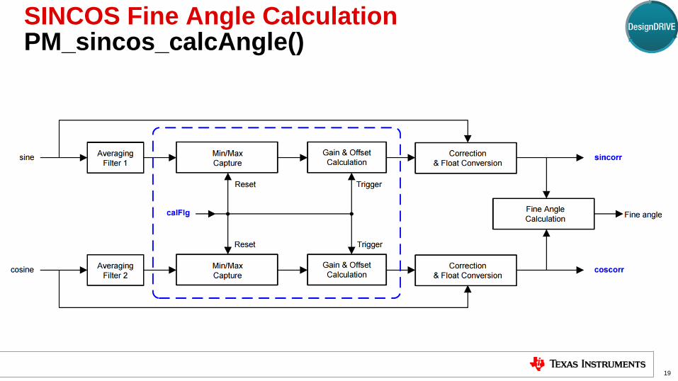
SINCOS Fine Angle Calculation PM_sincos_calcAngle()
19
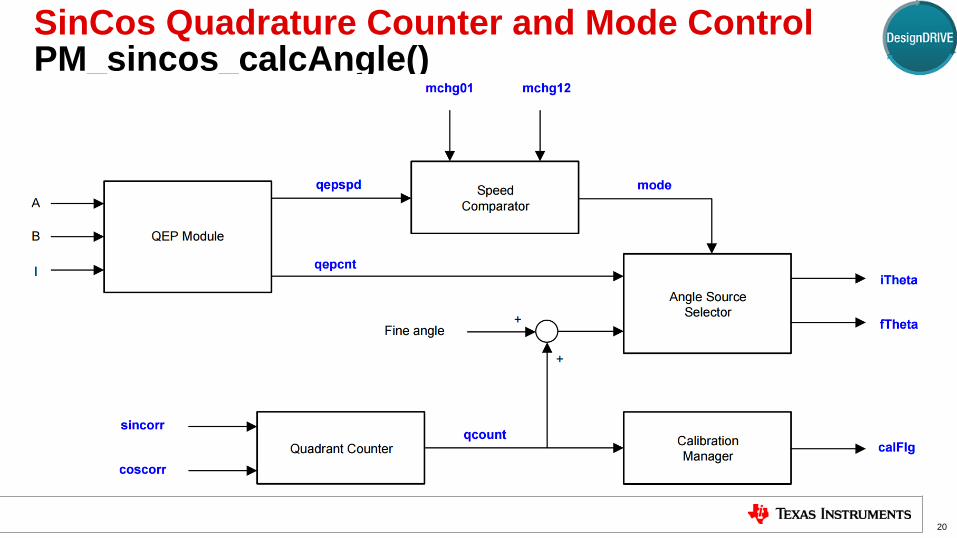
SinCos Quadrature Counter and Mode Control PM_sincos_calcAngle()
20

Angle calculation and mode selection
21

PM_SinCos Resource Requirements for TMS320F28379
22
Shared Resources
CPU and Memory Module Check CPU and Memory utilization for various functions Application to ensure enough CPU cycles and Memory are
allocated
Configurable Resources
eQEP Module and
IOs One QEP instance to support high speed
mode
Any QEP instance can be chosen. The
module and three corresponding IOs will then be dedicated for SinCos
Dedicated Resources
AD-C0 AIO Sine channel input AIO dedicated for SinCos
AD-D0 AIO Cosine channel input AIO dedicated for SinCos
AD-D2 AIO Index input AIO dedicated for SinCos
GPIO15 AIO CMPSS-4 high output IO dedicated for SinCos
GPIO14 AIO CMPSS-7 high output IO dedicated for SinCos
GPIO59 AIO CMPSS-8 high output IO dedicated for SinCos
Resource Name Type Purpose Usage Restrictions
Dedicated Resource – “hardwired and consumed” by the SinCos project.
Configurable Resource – can be customized by the user to choose an alternate instance, however, the
IDDK hardware has defined the resource used in the EnDat22 project.
Shared Resource - EnDat22 project uses a portion of the capabilities/channels available
TI Information – Selective Disclosure
DesignDRIVE Position Manager Resolver
An overview of the C2000 Resolver solution on Delfino™ ‘F2837x MCUs
23
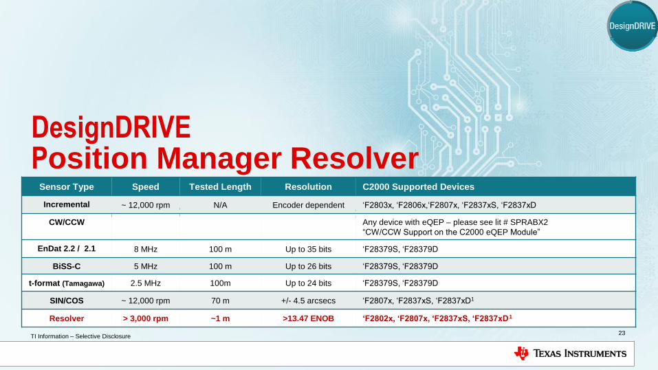
Sensor Type Speed Tested Length Resolution C2000 Supported Devices
Incremental ~ 12,000 rpm N/A Encoder dependent ‘F2803x, ‘F2806x,‘F2807x, ‘F2837xS, ‘F2837xD
CW/CCW Any device with eQEP – please see lit # SPRABX2
“CW/CCW Support on the C2000 eQEP Module”
EnDat 2.2 / 2.1 8 MHz 100 m Up to 35 bits ‘F28379S, ‘F28379D
BiSS-C 5 MHz 100 m Up to 26 bits ‘F28379S, ‘F28379D
t-format (Tamagawa) 2.5 MHz 100m Up to 24 bits ‘F28379S, ‘F28379D
SIN/COS ~ 12,000 rpm 70 m +/- 4.5 arcsecs ‘F2807x, ‘F2837xS, ‘F2837xD1
Resolver > 3,000 rpm ~1 m >13.47 ENOB ‘F2802x, ‘F2807x, ‘F2837xS, ‘F2837xD
1

How Does A Resolver Work?
25
• When the primary is excited with a sinusoidal carrier
wave, amplitude modulated sinusoidal signals are
generated in the secondary windings whose envelopes
are nothing but the sine and cosine of shaft angle
Position Manager Resolver Interface
• Observer constructs smooths sinusoidal output
between peak samples of the carriers.
• Minimizes error over all dynamic conditions
• Signal cleansing - band pass filter
• Decimation
• Error computation
• Band pass delay compensation
TI Whitepaper: SPRY212A
MotorResolver
Connector
Cable
A
B
X
F2837x
An
alo
g Su
b-S
yste
m
PMResolverLibrary
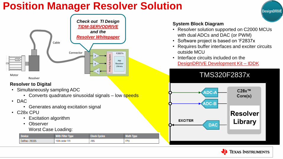
Position Manager Resolver Solution
System Block Diagram
• Resolver solution supported on C2000 MCUs
with dual ADCs and DAC (or PWM)
• Software project is based on ‘F2837x
• Requires buffer interfaces and exciter circuits
outside MCU
• Interface circuits included on the
DesignDRIVE Development Kit – IDDK
Resolver to Digital
• Simultaneously sampling ADC
• Converts quadrature sinusoidal signals – low speeds
• DAC
• Generates analog excitation signal
• C28x CPU
• Excitation algorithm
• Observer
Worst Case Loading:
Check out TI Design
TIDM-SERVODRIVE
and the
Resolver Whitepaper
TMS320F2837x
TI Information – Selective Disclosure
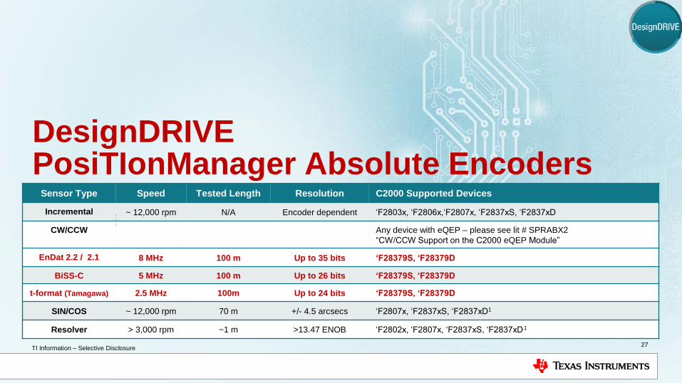
DesignDRIVE PosiTIonManager Absolute Encoders
EnDat2.2, EnDat 2.1
BiSS-C
Tamagawa T-format
27
Sensor Type Speed Tested Length Resolution C2000 Supported Devices
Incremental ~ 12,000 rpm N/A Encoder dependent ‘F2803x, ‘F2806x,‘F2807x, ‘F2837xS, ‘F2837xD
CW/CCW Any device with eQEP – please see lit # SPRABX2
“CW/CCW Support on the C2000 eQEP Module”
EnDat 2.2 / 2.1 8 MHz 100 m Up to 35 bits ‘F28379S, ‘F28379D
BiSS-C 5 MHz 100 m Up to 26 bits ‘F28379S, ‘F28379D
t-format (Tamagawa) 2.5 MHz 100m Up to 24 bits ‘F28379S, ‘F28379D
SIN/COS ~ 12,000 rpm 70 m +/- 4.5 arcsecs ‘F2807x, ‘F2837xS, ‘F2837xD1
Resolver > 3,000 rpm ~1 m >13.47 ENOB ‘F2802x, ‘F2807x, ‘F2837xS, ‘F2837xD
1
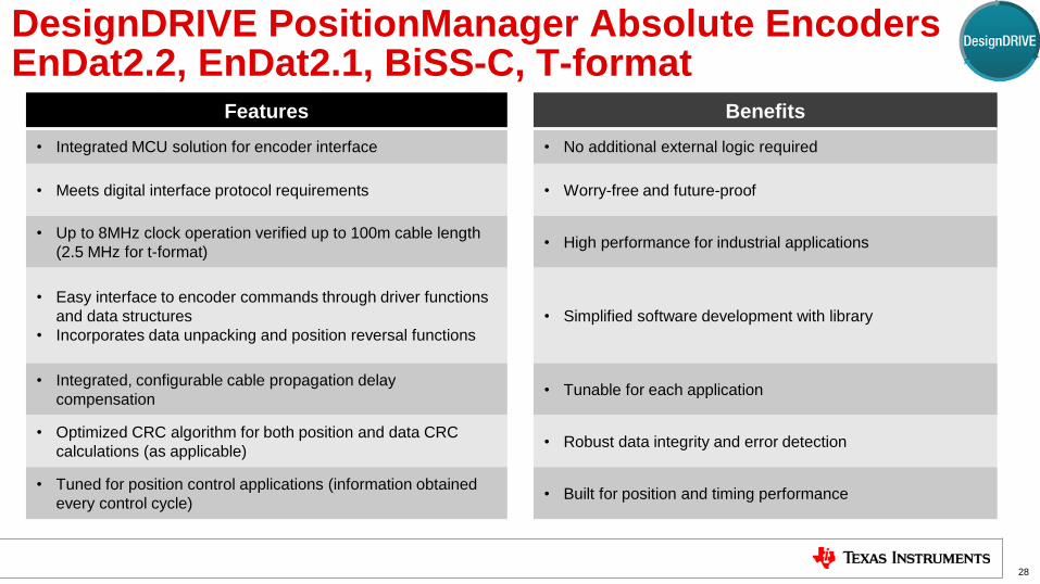
DesignDRIVE PositionManager Absolute Encoders EnDat2.2, EnDat2.1, BiSS-C, T-format
Features Benefits
• Integrated MCU solution for encoder interface • No additional external logic required
• Meets digital interface protocol requirements • Worry-free and future-proof
• Up to 8MHz clock operation verified up to 100m cable length
(2.5 MHz for t-format) • High performance for industrial applications
• Easy interface to encoder commands through driver functions
and data structures
• Incorporates data unpacking and position reversal functions
• Simplified software development with library
• Integrated, configurable cable propagation delay
compensation • Tunable for each application
• Optimized CRC algorithm for both position and data CRC
calculations (as applicable) • Robust data integrity and error detection
• Tuned for position control applications (information obtained
every control cycle) • Built for position and timing performance
28
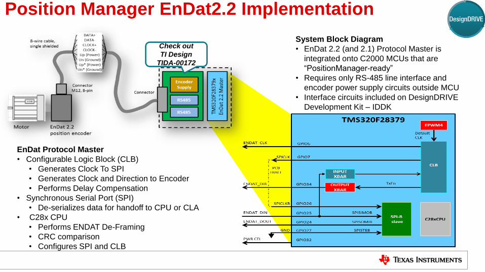
Position Manager EnDat2.2 Implementation
System Block Diagram
• EnDat 2.2 (and 2.1) Protocol Master is
integrated onto C2000 MCUs that are
“PositionManager-ready”
• Requires only RS-485 line interface and
encoder power supply circuits outside MCU
• Interface circuits included on DesignDRIVE
Development Kit – IDDK
EnDat Protocol Master
• Configurable Logic Block (CLB)
• Generates Clock To SPI
• Generates Clock and Direction to Encoder
• Performs Delay Compensation
• Synchronous Serial Port (SPI)
• De-serializes data for handoff to CPU or CLA
• C28x CPU
• Performs ENDAT De-Framing
• CRC comparison
• Configures SPI and CLB
Check out
TI Design
TIDA-00172

Position Manager BiSS-C Implementation
System Block Diagram
• BiSS-C Protocol Master is integrated onto
C2000 MCUs that are “Position Manager-ready” like the ‘F28379
• Requires only RS-485 line interface and
encoder power supply circuits outside MCU
• Interface circuits included on the
DesignDRIVE Development Kit – IDDK
BiSS-C Protocol Master
• Configurable Logic Block (CLB)
• Generates Clock To SPI
• Generates Clock and Direction to Encoder
• Performs Delay Compensation
• Synchronous Serial Port (SPI)
• De-serializes data for handoff to CPU or CLA
• C28x CPU
• Performs BiSS De-Framing
• CRC comparison
• Configures SPI and CLB
Check out TI Designs
TIDA-00175
TIDA-00179
TIDA-00180
TIDM-SERVODRIVE
TM
S3
20
F2
83
79X
BiS
S-C
Ma
ste
r

Position Manager T-format Implementation
System Block Diagram
• T-format Protocol Master is integrated onto
C2000 MCUs that are “Position Manager-ready” like the ‘F28379
• Requires only RS-485 line interface and
encoder power supply circuits outside MCU
• Interface circuits included on the
DesignDRIVE Development Kit – IDDK
BiSS-C Protocol Master
• Configurable Logic Block (CLB)
• Generates Clock To SPI
• Generates Clock and Direction to Encoder
• Performs Delay Compensation
• Synchronous Serial Port (SPI)
• De-serializes data for handoff to CPU or CLA
• C28x CPU
• Performs BiSS De-Framing
• CRC comparison
• Configures SPI and CLB
Check out TI Designs
TIDM-SERVODRIVE
TM
S3
20
F2
83
79X
BiS
S-C
Ma
ste
r
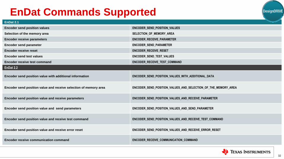
EnDat Commands Supported
32
EnDat 2.1
Encoder send position values ENCODER_SEND_POSITION_VALUES
Selection of the memory area SELECTION_OF_MEMORY_AREA
Encoder receive parameters ENCODER_RECEIVE_PARAMETER
Encoder send parameter ENCODER_SEND_PARAMETER
Encoder receive reset ENCODER_RECEIVE_RESET
Encoder send test values ENCODER_SEND_TEST_VALUES
Encoder receive test command ENCODER_RECEIVE_TEST_COMMAND
EnDat 2.2
Encoder send position value with additional information ENCODER_SEND_POSITION_VALUES_WITH_ADDITIONAL_DATA
Encoder send position value and receive selection of memory area ENCODER_SEND_POSITION_VALUES_AND_SELECTION_OF_THE_MEMORY_AREA
Encoder send position value and receive parameters ENCODER_SEND_POSITION_VALUES_AND_RECEIVE_PARAMETER
Encoder send position value and send parameters ENCODER_SEND_POSITION_VALUES_AND_SEND_PARAMETER
Encoder send position value and receive test command ENCODER_SEND_POSITION_VALUES_AND_RECEIVE_TEST_COMMAND
Encoder send position value and receive error reset ENCODER_SEND_POSITION_VALUES_AND_RECEIVE_ERROR_RESET
Encoder receive communication command ENCODER_RECEIVE_COMMUNICATION_COMMAND

BiSS-C Commands Supported
33
Name Description
PM_bissc_generateCRCTable This function generates table of 256 entries for a given CRC polynomial (polynomial) with specified number of bits (nBits). Generated
tables are stored at the address specified by pTable.
PM_bissc_getCrc Calculate the n-bit CRC of a message buffer by using the lookup table, to get the CRC of each byte. This function can be used for both
position and data CRC checks with corresponding CRC table and polynomial.
PM_bissc_getBits
This function is used for extracting the bits of interest from the receive data buffer. After every transaction, data received from the encoder
is stored in the receive buffer. This function can be used to extract position bits, CRC, CDS data etc. from the receive data buffer.
PM_bissc_setCDBit This function is used to configure what the CDM bit will be in the upcoming SCD transfer. Every BiSS frame ends with a timeout and
during this time no further clocks are transmitted by BiSS Master. Clock line MA is held to the state of the bit set by this function. The
inverse of the same is interpreted as the CDM bit by the slave.
PM_bissc_startOperation This function will initiate the BiSS-C transfer. To be called after PM_bissc_setupNewSCDTransfer. This function starts the transaction set
up by the PM_bissc_setupNewSCDTransfer function earlier. Note that the setup up and start operation are separate function calls. User
can setup the transfer when needed and start the actual transfer using this function call, as needed, at a different time.
PM_bissc_setupPeriph Setup for SPI, CLB and other interconnect XBARs for BiSS-C are performed with this function during system initialization. This function
needs to be called after every system reset. No transactions will be performed until the setup peripheral function is called.
M_bissc_setFreq Function to set the clock frequency.
Clock Frequency = SYSCLK/(4*BISSC_FREQ_DIVIDER)
- Ex: set BISSC_FREQ_DIVIDER to 25 for 2MHz operation
PM_bissc_setupNewSCDTransfer Setup a SPI and other modules for a given transaction. All the transactions should start with this command. This function call sets up the
peripherals for upcoming BiSS-C transfer but does not actually perform any transfer or activity on the interface. Once the transfer is setup
using this function, PM_bissc_startOperation can be called to start the transfer.
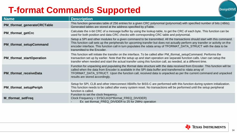
T-format Commands Supported
34
Name Description
PM_tformat_generateCRCTable This function generates table of 256 entries for a given CRC polynomial (polynomial) with specified number of bits (nBits).
Generated tables are stored at the address specified by pTable.
PM_tformat_getCrc Calculate the n-bit CRC of a message buffer by using the lookup table, to get the CRC of each byte. This function can be
used for both position and data CRC checks with corresponding CRC table and polynomial.
PM_tformat_setupCommand
Setup a SPI and other modules for a given command to be transmitted. All the transactions should start with this command.
This function call sets up the peripherals for upcoming transfer but does not actually perform any transfer or activity on the
encoder interface. This function call in turn populates the sdata array of TFORMAT_DATA_STRUCT with the data to be
transmitted to the Encoder.
PM_tformat_startOperation This function will initiate the transfer on the interface. To be called after PM_tformat_setupCommand. Performs the
transaction set up by earlier. Note that the setup up and start operation are separate function calls. User can setup the
transfer when needed and start the actual transfer using this function call, as needed, at a different time.
PM_tformat_receiveData
Function for unpacking and populating the tformat data structure with the data received from Encoder. This function will be
called when the data from Encoder is available in the SPI data buffer and transferred to rdata array of
TFORMAT_DATA_STRUCT. Upon the function call, received data is unpacked as per the current command and unpacked
results are stored accordingly.
PM_tformat_setupPeriph Setup for SPI, CLB and other interconnect XBARs for BiSS-C are performed with this function during system initialization.
This function needs to be called after every system reset. No transactions will be performed until the setup peripheral
function is called.
M_tformat_setFreq Function to set the clock frequency.
Clock Frequency = SYSCLK/(4*tformat_FREQ_DIVIDER)
- Ex: set tformat_FREQ_DIVIDER to 25 for 2MHz operation
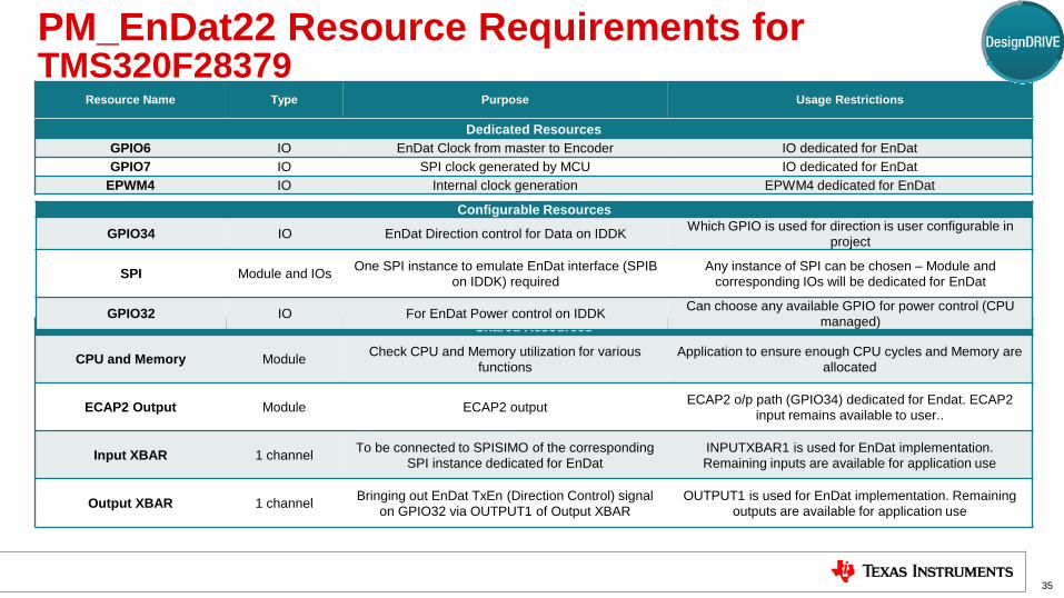
PM_EnDat22 Resource Requirements for TMS320F28379
35
Shared Resources
CPU and Memory Module Check CPU and Memory utilization for various
functions Application to ensure enough CPU cycles and Memory are
allocated
ECAP2 Output Module ECAP2 output ECAP2 o/p path (GPIO34) dedicated for Endat. ECAP2
input remains available to user..
Input XBAR 1 channel To be connected to SPISIMO of the corresponding
SPI instance dedicated for EnDat INPUTXBAR1 is used for EnDat implementation.
Remaining inputs are available for application use
Output XBAR 1 channel Bringing out EnDat TxEn (Direction Control) signal
on GPIO32 via OUTPUT1 of Output XBAR OUTPUT1 is used for EnDat implementation. Remaining
outputs are available for application use
Configurable Resources
GPIO34 IO EnDat Direction control for Data on IDDK Which GPIO is used for direction is user configurable in
project
SPI Module and IOs One SPI instance to emulate EnDat interface (SPIB
on IDDK) required Any instance of SPI can be chosen – Module and
corresponding IOs will be dedicated for EnDat
GPIO32 IO For EnDat Power control on IDDK Can choose any available GPIO for power control (CPU
managed)
Dedicated Resources
GPIO6 IO EnDat Clock from master to Encoder IO dedicated for EnDat
GPIO7 IO SPI clock generated by MCU IO dedicated for EnDat
EPWM4 IO Internal clock generation EPWM4 dedicated for EnDat
Resource Name Type Purpose Usage Restrictions

PM_BiSS-C Resource Requirements for TMS320F28379
36
Shared Resources
CPU and Memory Module Check CPU and Memory utilization for various functions Application to ensure enough CPU cycles and Memory are
allocated
ECAP2 Output Module ECAP2 output ECAP2 o/p path (GPIO34) dedicated for BiSS. ECAP2 input
remains available to user..
Input XBAR 1 channel To be connected to SPISIMO of the corresponding SPI
instance dedicated for BiSS-C INPUTXBAR1 is used for BiSS-C implementation. Remaining
inputs are available for application use
Configurable Resources
BiSS-TxEn / GPIO34 IO For Transmit Enable control of RS485 Can choose any IO.
GPIO34 is used on IDDK and example projects
SPI Module and IOs One SPI instance to emulate BiSS interface (SPIB on
IDDK) required Any instance of SPI can be chosen – Module and corresponding
IOs will be dedicated for BiSS-C
Biss-PwrCtl / GPIO32 IO For BiSS-C Power control on IDDK Can choose any available GPIO for power control.
GPIO34 is used on IDDK and example projects
Dedicated Resources
GPIO6 IO BiSS clock from master to Encoder IO dedicated for BiSS-C
GPIO7 IO SPI clock generated by MCU IO dedicated for BiSS-CBiSS-C
EPWM4 IO Internal clock generation EPWM4 dedicated for BiSS-C
Resource Name Type Purpose Usage Restrictions
Dedicated Resource – “hardwired and consumed” by the BiSS-C project.
Configurable Resource – can be customized by the user to choose an alternate instance, however, the
IDDK hardware has defined the resource used in the BiSS-C project.
Shared Resource - BiSS-C project uses a portion of the capabilities/channels available

T-format Resource Requirements for TMS320F28379
37
Shared Resources
CPU and Memory Module Check CPU and Memory utilization for various functions Application to ensure enough CPU cycles and Memory are
allocated
Output XBAR 1 channel Bringing out tformat TxEn (Direction Control)
signal on GPIO32 via OUTPUT1 of Output
XBAR
OUTPUT1 is used for implementation. Remaining outputs are available for application use.
Input XBAR 1 channel To be connected to SPISIMO of the corresponding SPI
instance dedicated for BiSS-C INPUTXBAR1 is used for mplementation. Remaining inputs are
available for application use
Configurable Resources
SPI Module and IOs One SPI instance to emulate t-format interface (SPIB on
IDDK) required Any instance of SPI can be chosen – Module and corresponding
IOs will be dedicated for t-format
PwrCtl / GPIO32 IO For encoder control on IDDK Can choose any available GPIO for power control.
GPIO32 is used on IDDK and example projects
TxEn IO Direction control on data GPIO34 is used for this purpose on IDDK and
example projects. User can choose any GPIO with OUTPUTXBAR1 mux option
Dedicated Resources
GPIO7 IO SPI clock generated by MCU IO dedicated for t-format implementation
EPWM4 IO Internal clock generation EPWM4 dedicated for t-format
Resource Name Type Purpose Usage Restrictions
Dedicated Resource – “hardwired and consumed” by the BiSS-C project.
Configurable Resource – can be customized by the user to choose an alternate instance, however, the
IDDK hardware has defined the resource used in the BiSS-C project.
Shared Resource - BiSS-C project uses a portion of the capabilities/channels available

Position Manager - TMS320F28379x System Resource Requirements Reference
38
QEP ADC CMPSS DAC SPI CLB PWM GPIO C28 Cyc/
Sample Pgm (KB)
RAM
(KB)
QEP 1 QEP
peripheral 90 0.2 .03
Resolver 2 Ch 1 Ch EPWM6 190 0.8 0.2
SinCos 1 3 Ch 3 6 642 1.4 0.05
EnDat 2.2 1 Y EPWM4 2x – DIR,
PWR
Refer to
table* 4.6 0.5
BiSS 1 Y EPWM4 1 PWR Refer to
table* 2.3 0.4
Tamagawa 1 Y EPWM4 2x – DIR,
PWR
Refer to
table* 1.8 0.3
*Different functions have different execution times – details captured in corresponding library documentation
** Complete resource requirements specified in the “Resource requirements” section of corresponding lib user guide

EnDat Testing Results at Heidenhain Lab
39
Encoder Name Type Resolution Cable Length
In Meters
Max EnDat
Clock
In MHz
Test Result
ROC425 Rotary 25-bits 70m 8MHz Pass
LC415 Linear 35-bits 70m 8MHz Pass
RCN8310 Rotary 29-bits 70m 8MHz Pass
ROQ437 Multi Turn 25-bits,
12-bits (Turns) 70m 8MHz Pass
LIC211 Linear 32-bits 70m 8MHz Pass
ROC413 Rotary 13-bits 70m 8MHz Pass
Note: Cable lengths up to 100m have also been tested with some of the encoders. Users are free to
deploy longer cable lengths, perform delay compensation, switch to higher EnDat clock frequencies and
perform tests.

BiSS Testing Results at TI Lab
40
Encoder
Manufacturer Encoder Name Type Resolution
Cable
Length
In Meters
Max BiSS
Clock
In MHz
CD interface
used
Test
Result
Lika HS58S18/I7 Rotary 18-bits
(padded to 24bits) 100m 3.33MHz Yes Pass
Kuebler 8.F5863.
1426.C423 Rotary 26-bits (12+14) 100m 5MHz No Pass
Note: Users are free to deploy longer cable lengths, perform delay compensation,
switch BiSS-C clock frequency and perform tests.

T-format Testing Results at TI Lab
41
Encoder
Manufacturer Encoder Name Type Resolution
Cable
Length
In Meters
Max t-format
Clock
In MHz
Test
Result
Tamagawa TS5643N100 Rotary 17-bits
(padded to 24bits) 70m 2.5 Mbps Pass
Tamagawa TS5700N8501 Rotary 24-bits 70m 2.5 Mbps Pass
Note: Users are free to deploy longer cable lengths, perform delay compensation,
and perform tests on their own.
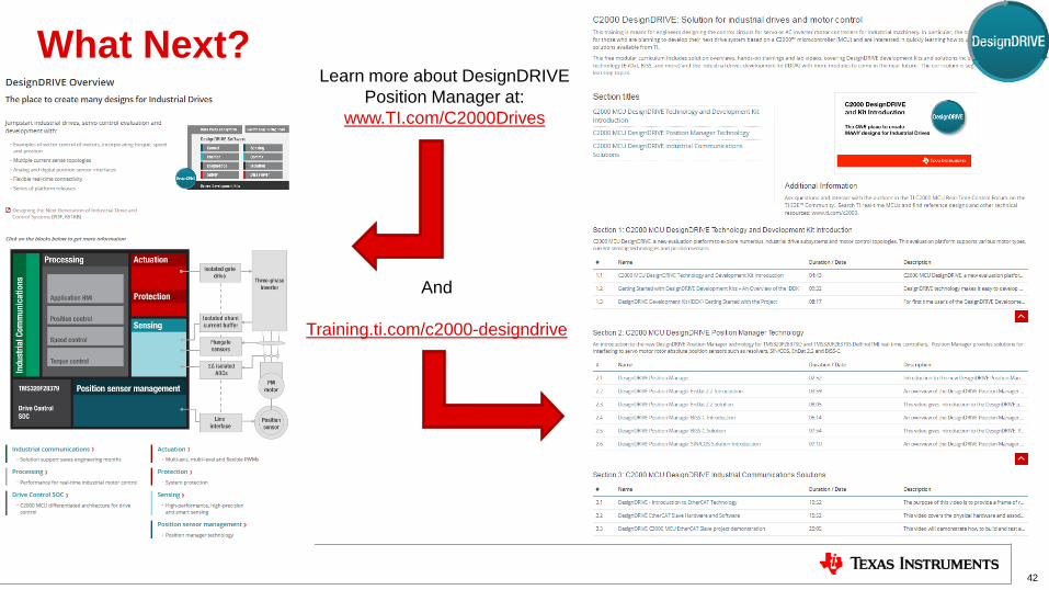
What Next?
42
Learn more about DesignDRIVE
Position Manager at:
www.TI.com/C2000Drives
And
Training.ti.com/c2000-designdrive
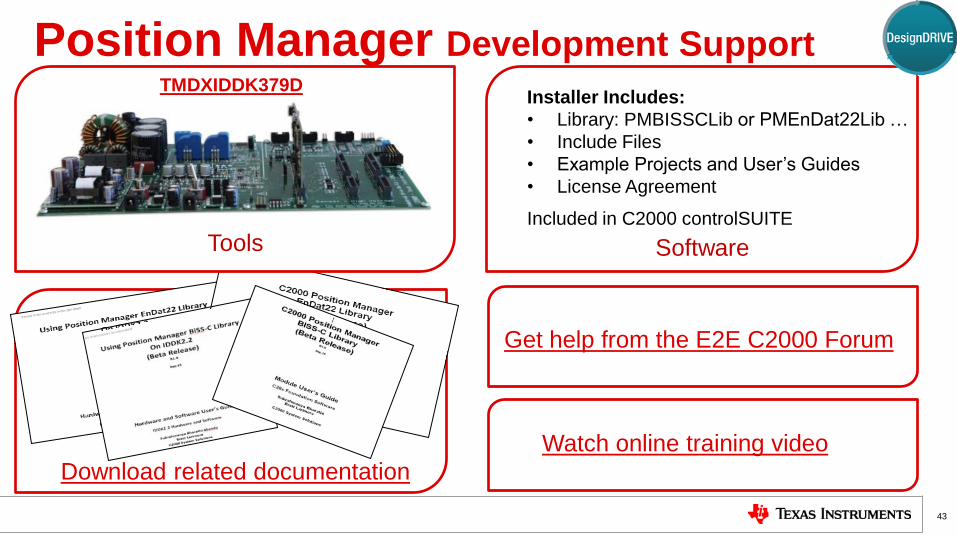
Tools
Position Manager Development Support
43
TMDXIDDK379D
Get help from the E2E C2000 Forum
Software
Included in C2000 controlSUITE
Installer Includes:
• Library: PMBISSCLib or PMEnDat22Lib …
• Include Files
• Example Projects and User’s Guides
• License Agreement
Download related documentation
Watch online training video


