Download - The amateur mechanic - archive.org
ECHANIG-X:FREDERICK COLLINS
I i|) IK
in
mi!|M,':U.'ii:'!i'
mm. mmmmmmmmmnw

Hntt Q\alkgt of Agriculture
At (HortteU MniUEtaitB
atljaca, Jf. ^.
ICibratg

&&iiiUi i>.«>v^.««ity Library
1S5.C55
The amateur mechanic,
3 1924 003 595 141

The original of tliis book is in
tine Cornell University Library.
There are no known copyright restrictions in
the United States on the use of the text.
http://www.archive.org/details/cu31924003595141
The
AMATEUR MECHANIC
By A. Frederick Collins
The Amateur Mechanic
How to Fly
The Home Handy Book
Keeping Up with YourMotor Car
The Book of Wireless
The Book of Stars
The Book of Magic
The Book of Electricity
D. Applbton & CompanyPublishers New York

The
AMATEUR MECHANIC
BY
A. FREDERICK COLLINSAXITHOB OF "eEEPINO tTP WITH TOUB HOTOB CAB/' "HOW TO FLT/
"the BOOE 07 ELECTBICtIT," BIC.
FULLY ILLUSTRATED
D. APPLETON AND COMPANYNEW YORK LONDON
1919

COPTMGHT, 1918, BT
©. APPLETON AND COMPAMf
Printed in the United States of America
TOMT NIECE AND NEPHEW
ETHEL AND EARL COLLINS

A WORD TO YOU
Don't do anything until you have read this book
!
I might qualify the above statement by saying
that if you are an amateur it will pay you to scan
the following pages before you try to do mechanical
things.
The idea I have tried to carry out is to parallel
the case of the locomotive engineer. You know, of
course, that he did not build the engine he drives
but he knows every part of it, exactly how it works,
how to run it to get the most power, or speed, or
both, out of it with the highest fuel economy and,
further, if he should have a breakdovsTi on the road
he knows just how to make whatever repairs are
needed to go on with his run.
I have presupposed that you know how to use
ordinary tools (though I have explained the modeof operation of a few that relate to the art of meas-
uring) and J have not told how to make the various
devices and machines described but what I have
gone into is how things are constructed, how to makesimple calculations to get the result you want, howthe machine works, how to run it to get the most
light, heat or power out of it at the least cost for
fuel, upkeep and expenditure of labor, how to repair
vii
A WORD TO YOU
it when something happens, and, lastly, how to
buy it.
A further purpose of this book is to tell about the
kinds of materials that are used in building and the
appliances that are employed in operating a home
or a farm so that if you are a householder or a hus-
bandman you can enjoy all the benefits of the elec-
trical and mechanical arts known that make for the
comfort, convenience, economy and safety of your-
self and family and so make life worth living.
A. rBEDEEiCK Collins.
600 Riverside Drive,
New York City. '
viu
CONTENTS
I. Rules and Tools tor Measuring ... 1
A carpenter's boxwood rule—The triangular
boxwood rule and scale—A pattern maker's
shrinkage rule—The use of flexible rules
—
About tape measures—The carpenter's steel
square—Laying out an octagon or 8-square
—
The brace measure table—The essex board
measure table—The rafter framing table—Thevernier—The vernier caliper—The micrometer
caliper—Gauges for testing and comparing
—
The protractor—The planimeter.
II. When You Build Youk House ... 25
Comparative cost of buildings—Kinds of ma-terials to use—Now about lumber—The waywood is seasoned—^How to tell good lumber
—
Using lumber to the best advantage—The frame' of a building—^Kinds of woods for building
—
Where to use these woods—How to preserve
wood—Bricks and brickwork—Plaster for walls
—About laying brick—Stone and stonework
—
Stucco for buildings—^Building with concrete
—
Materials for concrete and where to use them
—
Mixing concrete—^Placing concrete—^Tinishing
concrete surfaces.
III. A Water System for Your Place . . 46
Kinds of water supplies—How to purify water—The amount of water needed—Schemes for awater supply—The gravity system—The air
pressure or pneumatic system—How to figure
the capacity of a tank—The weight of water
—
The automatic air, or auto-pneumatic system
—
About pimips and pumping—The action of
ix
CONTENTSCHAPTEB PAGE
pumps—To prevent pipes from freezing
—
When a water pipe is frozen—A work on
plumbing and sewage.
IV. A Heating Plant fob Yotje Home . . 63
What heat is—^What temperature means—Howheat warms a room—How heat is measured
—
About heating and ventilating—Kinds of heat-
ing plants—To find the size of heater needed
—Electric heating apparatus—How to get good
ventUation.
V. How Machines are Made and Used . . 75
To find the speed of a shaft, pulley or fly-
wheel—How to find the size of a puUey—^Howto figure the size of belt needed—^How to splice
a belt—A good belt dressing—Gears and toothed
wheels—Figuring the size of gears—Friction
and what it does—How to reduce friction—Fig-
uring the size of gears—Friction and what it
does—How to reduce friction—The use of lubri-
cants—How to find the H.P. needed to drive amachine.
YI. Putting Wind and Water Power to Work 94
What wind power is—The parts of a windmill
—Sizes of windmills for primping—Sizes ofwindmills for machinery—The height of efficient
winds—About towers for windmills—^Whatwater power is—Kinds of water wheels—Thejet water wheel—The water turbine—How the
turbine is made and works—The hydraulic ram.—What "heat of water" means—To find thehorse power of a water wheel—To find the
amount of water delivered by a ram.
VII. Making the Steam Engine Work for You 112
About the energy of steam—What steam pres-
sure is—How steam is measured—How a steamboiler is made—The fittings of a boiler—How asteam engine is made—How the engine works
—
The latent heat of steam—What the flywheel

CONTENTSOHAfTEB PAGE
does—^Packing for stuffing boxes—^How to figure
the horse power of a boiler—How to figure the
H.P. of your engine.
Vin. UsiiTG Hot Aib, Gas, Gasoline and Oil En-gines 132
The hot air engine—^How the hot air engine
works—How to use a hot air engine—The gas
engine—The parts of a gas engine—How a gas
engine works—How a gasoline engine works
—
The parts and action of the carburetor—How anoil engine works—Sizes and power of engines—
•
How to figure the horse power of a gas, gaso-
line or oil engine.
IX. How TO Hitch Up Power .... 148
How to use wind power—How to use waterpower—How to use steam power—^Using hotair power—How to use oil and gasoUne power
—
How to use your automobile as a power plant.
X. Installing a Home Ice-Making Machine . 157
What cold is—How cold is produced—Aboutice-making machines—How to insulate the brine
mains—^How to build a refrigerator—Some facts
about ice making—^What it costs to make ice.
XL Electricity in the Home and on the Farm . 166
What to know about electricity—^What an elec-
tric installation consists of—How a dynamo is
made—How a djTiamo generates current—Theelectric motor—How a storage battery is made
—
How to use a storage battery—The switchboardand its instruments—Wire for the transmissionline—^What an electric plant will do.
Xn. Useful Rules and Tables .... 183
INDEX 187
XI


LIST OF ILLUSTRATIONS
1.—Eules and scales
2.—The steel tape measure ....3A.—The carpenter's steel square . .
3B.—^rising the steel square . .; . .
4.—The vernier
5.—The micrometer
6.—^A level and its plumb glass
7.—^A few other useful gauges
8.—The protractor for finding angles and measur-
ing them in degrees ....9.—^A cheap planimeter for measuring the area of
any plane surface ....10.—Cross section view of tree showing medullary
rays and annual rings....11.—How timber should be cut
12.—The frame of a building ....13.—Bands of bonds used in laying brick
14.—Kinds of stone and stone work .
15.—How stucco is put on ... .
16.—The only tools you need for concrete work
17.—^Forms for placing concrete
18.—Some concrete block designs .
19.—The pasteur water filter ....20.—^A home-made water distilling apparatus .
21.—^A gravity water system ....22.—The hydro-pneimiatic system .
23A.—The auto-pneumatic water pump .
23B.—The auto-pneumatic water system .
24.—^Kinds of pumps
xiii
3
6
8
9
14
18
19
21
22
23
27
29
30
36
37
39
43
44
45
48
50
52
53
56
57
58
LIST OF ILLUSTRATIONSnOimS FAQE
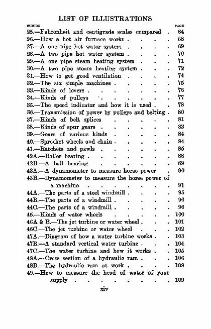
25.—Fahrenheit and centigrade scales compared . 64
26.—^How a hot air furnace works .... 68
27.^A one pipe hot water system .... 69
28.—^A two pipe hot water system .... 70
29.—^A one pipe steam heating system ... 71
30.—^A two pipe steam heating system ... 72
31.—How to get good ventilation .... 74
32.—The six simple machines 75
33.—Kinds of levers 76
34.—Kinds of pulleys • 77
35.—The speed indicator and how it is \iaed . . 78
36.—Transmission of power by pulleys and belting . 80
37.—Kinds of belt splices 81
38.—Kinds of spur gears 83
39.—Gears of various kinds 84
40.—Sprocket wheels and chain 84
41.—^Ratchets and pawls 85
42A.—Roller bearing 88
42B.—A ball bearing 89
43A.—^A dynamometer to measure horse power . 90
43B.—Dynamometer to measure the horse power of
a machine 91
44A.—The parts of a steel windmill.... 95
44B.—The parts of a windmill 96
44C.—The parts of a windmill 96
45.—Kinds of water wheels 100
46A & B.—The jet turbine or water wheel . . . 101
46C.—The jet turbine or water wheel . . . 102
47A.—^Diagram of how a water turbine works . . 103
47B.—A standard vertical water turbine . . . 104
47C.—The water turbine and how it works . . 105
48A.—Cross section of a hydraulic ram . . . 106
48B.—The hydraulic ram at work .... 108
49.—^How to measure the head of water of your
supply 109
XIV
LIST OF ILLUSTRATIONSFIOtTBE PAGE
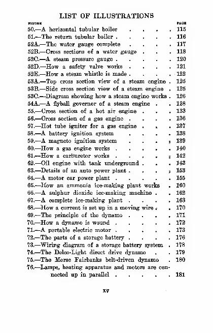
50.—A horizontal tubular boiler .... 115
51.—The return tubular boiler 116
52A.—The water gauge complete .... 117
52B.—Cross sections of a water gauge . . . 118
52C.—A steam pressure gauge 120
52D.—How a safety valve works .... 121
52E.—^How a steam whistle is made . . . . 122
53A.—Top cross section view of a steam engine . 125
53B.—Side cross section view of a steam engine . 125
53C.—^Diagram showing how a steam engine works . 126
54A.—A flyball governor of a steam engine . . 128
55.—Cross section of a hot air engine . . . 133
56.—Cross section of a gas engine .... 136
57.—^Hot tube igniter for a gas engine . , . 137
58.—^A battery ignition system .... 138
59.—A magneto ignition system . . . , 139
60.—How a gas engine works 140
61.—^How a carburetor works . . . . s 142
62.—Oil engine with tank underground . . . 143
63.—^Details of an auto power plant . . . i 153
64.—^A motor car power plant 155
65.—^How an ammonia ice-making plant works . 160
66.—A sulphur dioxide ice-making machine . . 162
67.—^A complete ice-making plant .... 163
68.—^How a current is set up in a moving wire .• . 170
69.—The principle of the dynamo .... 171
70.—^How a dynamo is wound 172
71.—^A portable electric motor 173
72.—The parts of a storage battery .... 176
73.—Wiring diagram of a storage battery system. . 178
74.—The Delco-Light direct drive dynamo . . 179
75.—The Morse Fairbanks belt-driven dynamo . 180
76.—^Lamps, heating apparatus and motors are con-
nected up in parallel 181
XV

THEAMATEUR MECHANIC
CHAPTER I
EULES AND TOOLS FOE MBASUEING
All tools for measuring may be divided into two
classes, and these are (1) ndes and instruments for
making actual measurements, and (2) gauges for
testing and comparing.
A rule is simply a strip of wood, or metal, or other
material, having a straight edge and whose surface is
graduated into inches or centimeters ^ and fractions
thereof. This graduated surface is called a scale,
and sometimes the rule itseK is spoken of as a scale.
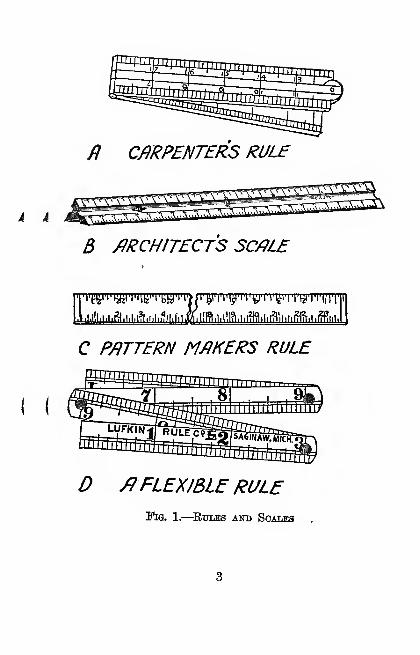
A Carpenter's Boxwood Rule.—Carpenters'
rules are not all made alike, for some are 1 foot-4 fold,
some are 2 foot-2 fold, those in general use are 2 foot^
4 fold, others are 3 foot-4: fold and, finally, there are
4 foot-4 fold rules.
But a regular carpenter's rule is taken to mean a
2 foot-4 fold boxwood rule, the scales being divided
into eighths, tenths, twelfths and sixteenths of an
•A unit of lineal measurement used in the Metric System.
1

THE AMATEUR MECHANIC
inch. To measure closely, turn the rule on its edge
so that the graduated lines set against the board or
whatever it is you are measuring. A rule of this
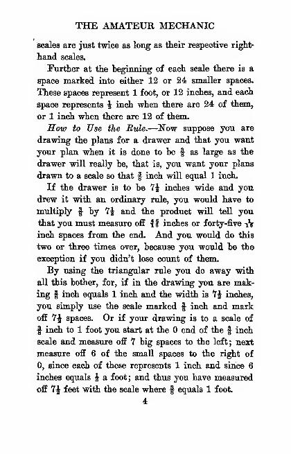
kind is shown at A in Fig. 1.
The Triangular Boxwood Rule and Scale.—^If
you are making machine or ardiitectural drawings
you should by all means have one of these scales, for
with it you can draw to scale, or get the actual di-
mensions from drawings that have been made to
scale, both easily and quickly.
This rule, which is shown at B, has, as you will
see, three sides and each side has two surfaces^ mak-
ing six surfaces in all. On one of these surfaces
there is an ordinary twelve-inch scale graduated in
inches and a different scale is graduated on each end
of the other five surfaces, thus making eleven scales
all told. These other ten scales are graduated to ^,
^,-k> i, %, i, fJij li and 3 inches to the foot.
To Learn the Bide.—^Lay it on the table with the
twelve-inch scale away from you, just as though you
were going to draw a line and so that it reads from
on the left to *12 on the right. Now turn the rule
toward you until the next side is uppermost, and you
wiU see that the upper left-hand scale reads to f of
an inch toward the right, and that the upper right-
hand scale reads to f of an inch toward the left.
The lower left-hand scale, you will observe, reads
to 3 inches toward the right^ and that the lower
right-hand scale reads to li inches toward the left.
You will also note that the left-hand upper and lower
i i
( (
fl CmPENTERS RULB
B mCHITECTS 5C/JL£
.>,i,i!i,i,i.fl,i,i,i?i,i,i
TO^|i'^i'i'iMil'iTiii'n'triTlii'IT|,'lT
C P/iTTERN M/fKERS RULE
/fFLEXIBLE RULEFig. 1.—^RuuBS and Scales
THE AMATEUR MECHANIC
scales are just twice as long as their respective right-
hand scales.
Further at the beginning of each scale there is a
space marked into either 12 or 24 smaller spaces.
These spaces represent 1 foot, or 12 inches, and each
space represents i inch when there are 24 of them,
or 1 inch when there are 12 of them.
How to Use the Rule.—ISaw suppose you are
drawing the plans for a drawer and that you want
your plan when it is done to be f as large as the
drawer will really be, that is, you want your plans
drawn to a scale so that f inch will equal 1 inch.
If the drawer is to be 7i inches wide and you
drew it with an ordinary rule, you would have to
multiply f by 7i and the product will tell you
that you must measure off H inches or forty-five iV
inch spaces from the end. And you would do this
two or three times over, because you would be the
exception if you didn't lose ooimt of them.
By using the triangular rule you do away with
all this bother, for, if in the drawing you are mak-
ing f inch equals 1 inch and the width is 1i inches,
you simply use the scale marked f inch and markoff 7J spaces. Or if your drawing is to a scale of
f inch to 1 foot you start at the end of the f inch
scale and measure off 7 big spaces to the left; next
measure off 6 of the small spaces to the right of
0, since each of these represents 1 inch and since 6
inches equals J a foot; and thus you have measured
off 74 feet with the scale where f equals 1 foot
4
RULES AND TOOLS FOR MEASURING
In the same way you can use any scale on the
rule and make working drawings to any scale within
its limitations and without any calculation whatever.
The chief thing to remember is that each of these
scales starts off with a space divided into 12 parts
or 24 parts depending on the size of the scale and
whether this space represents 1 foot and the smaller
spaces i an inch or 1 inch, as the case may be. Arule of ftis kind can be bought ^ for as little as sixty
cents.
A Pattern Maker's Shrinkage Rule.—^When a
casting is made the metal shrinks on cooling, and to
allow for this shrinkage the pattern must be made a
little larger than the casting is to be.
A shrinkage rule, see 0, is graduated to allow for
the shrinkage of the metal you are using. The spac-
ing of the graduations is used to measure the patterns
you are making, while the figures on the graduations
show the actual size the castings will be.
The Use of Flexible Rules.—^Rules made of
cardboard, celluloid, thin steel and wood are useful
for measuring curved surfaces.
Cardboard rules can be bought* for a couple of
cents each; celluloid rules 6 inches long can be had
for five cents each, and very thin spring-tempered
rules for machinists * can be purchased in any lengths
•Triangular boxwood rules can be bought of the L. E.Knott Apparatus Co., Boston, Mass., and also of Keuffel andEsser Co., 127 Pulton St., New York.•The L. E. Knott Apparatus Co. sells these.* These rules are sold by Hammacher, Schlemmer and Co.,
Fourth Ave. and 13th St., New York.
5
THE AMATEUR MECHANIC
from 1 inch up to 48 inches for fifteen cents for the
shortest up to $7 for the longest.
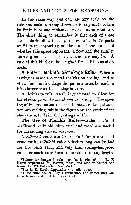
Where measurements of doors, windows, boilers.
Fig. 2.
—
The Steel Tape Measure
eta, are to be made a flexible folding wood rule will
be found very convenient, while a flexible steel fold-
ing rule, as shown at D, is a good one to use for
metal work.
About Tape Measures.—These elongated rules
are used by every carpenter, mason, contractor, sur-
6
RULES AND TOOLS FOR MEASURING
veyor and engineer and you ought to have one in your
kit of tools.
An ordinary tape measure, see A in Fig. 2, con-
sists of a thin, flexible steel tape from :| to f inch
wide and from 25 to 100 feet long; it is graduated
on one side into feet, inches and eighths and is fitted
into a hard leather case. The tape can he reeled up
hy a handle which folds in flush with the side of
the case.
The Boe tape measure has a right angle attachment
which permits it to be used quickly and accurately
for laying out right angles as shown at B. It is
based on the well-known trigonometrical formula that
a triangle whose sides measure 6, 8 and 10 feet makes
a right angle. Hence, by using this tape measure
you can get a perfect right angle without a surveying
instrument or tools or help of any kind.
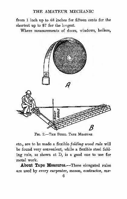
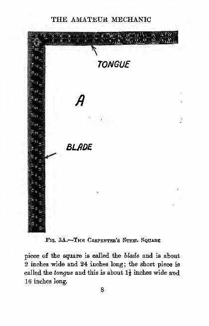
The Carpenter's Steel Square.—The ordinary
carpenter's square, or steel square, or framing square,
as it is variously called, is used not only as a rule, a
straight edge and a try square in building construc-
tion but also for laying out octagons, or 8 squares,
as they are called, finding the square feet in boards,
or hoard measure as it is termed, finding the lengths
and cuts of braces and also of common, hip, valley
and jack rafters for different pitches of roofs.
The ordinary steel square is formed of two parts
though these are usually made of one piece of steel
about -J of an inch thick and which set at right angles
to each other as shown at A in Fig. 3. The long
7
THE AMATEUR MECHANIC
Fig. 3A.--Thb Carpenter's Stbhc^ Square
piece of the square is called tlie hlade and is about
2 inches wide and 24 inches long ; the short piece is
called the tongue and this is about li inches wide and
16 inches long.
8

RULES AND TOOLS FOR MEASURING
The side of the square with the maker's name
stamped on it is called its face and the other and op-
posite side is called its hack. It is usually divided
into ihs, -h, -h, tV, ^ and ^ inch scale divisions.
Laying Out an Octagon or 8-Square.—^Along
the middle of the tongue of the square you wiU find
THE AMATEUR MECHANIC
scale of the square, set them to as many spaces of
the scale as there are inches in any one side of the
square you have drawn. Lay this distance off on
both sides of each middle point, as shown at B 1,
2, 3, 4, 5, 6, 7 and 8. Then connect these points
with lines starting at 1 and drawing to 2, from 2 to
3, and so on until the octagon is complete.
You will ohserve that it is the 8-square scale on the
square and not the square itself that is the important
part of laying out octagons and that a scale of this
kind marked on a rule would serve the purpose just
as well.
The Brace Measure Table.—^Along the center of
the back of the tongue of your square you will find a
table of numbers and you will see that there are two
numbers, one above the other, which are equal and one
number to the left of them.
The purpose of this table is to make it possible
for a carpenter to instantly determine the length of
a brace when its ends are to be fixed at equal distances
from the intersecting post, beam, shelf, wall or any
other like construction.
The table is used like this : Suppose that you have
a shelf you want to fix to the wall with a pair of
braces, and that you want to have each end of each
brace 9 inches from the point where the wall and the
shelf intersect each other. Look at the table and
you wiU see that after the set of number 9 the number
12.72 is just to the left of it.
This number—12.72—is the length in inches, then,
10
RULES AND TOOLS FOR MEASURING
that you must make the short side of the brace, so
cut a piece of wood a little longer than 12.72 inches
—say 15 inches—if the brace is to be made 12.72
inches on one side, l^ow put it in your miter box
and cut off each end at an angle of 45 degrees, when
it will just fit into the corner with each end 9 inches
away from the intersection of the shelf and wall, as
shown at C.
This table is based on the same trigonometrical
relations between the lengths of the sides of a right
triangle as that described under the caption of Tape
Measures.
The Essex Board Measure Table.—The term
hoard measure means the number of square feet in a
board 1 inch thick. A board 2 inches thick will
have twice as many hoard feet in it as a board 1 inch
thick, and so on.
Of course a board 12 inches wide will have as
many feet in it as it is feet long and you don't have
to do any figuring to know the answer. But if the
board is more or less than 12 inches wide you will
have to make a small calculation to find the board
feet in it. If, for instance, the board is 8 inches
wide and 10 feet long, to figure out the board feet
you will have to find the number of square inches in
it first and then divide the product by 144.
But if you use the Essex board measure table on
the square you can instantly find the number of board
feet in a board without any calculation. The start-
ing point in this table is always the figure 12. If,
11
THE AMATEUR MECHANIC
now, you want to find the board feet in a board 8
inches wide and 10 feet long, simply follow the
graduated line on the left of the table down to the
figure 10, then follow the cross line toward the left
to 8, and you wiU find that the number under 8 is 6
;
you wiU also see that 6 is to the left of the cross line
and 8 is to the right, which means that there is 6
feet and t% inches, board measure, in the board.
But if the board is wider than 12 inches, then you
follow the cross line toward the right to the number
representing the length of the board you want to
measure. If the board is 2 inches, multiply the
result you get by 2, which will give you the board
measure for that thickness.
The Rafter Framing Table,—On the back of a
good steel square you will find a table of numbers
marked between the scales of inches on the tongue.
With this table you can find the lengths for rafters
of known rise and run for a given pitch. The rise
of a rafter is the vertical height from its ridge end
to a horizontal line on a level with its foot.
The run of a rafter is the reach in length from the
outside edge of its foot to a point exactly under its
ridge end on a horizontal line level with its foot.
The pitch of a rafter is the ratio of the rise to twice
the run, which is usually equal to the width of the
building.
N'ow, if you will look at the left of the table you
will see a series of figures, thus
:
12

RULES AND TOOLS FOR MEASURING
PITCH
12—4
THE AMATEUR MECHANIC
having a ^ pitch and a run of 20 feet will be 24' 0"
T% ", or 24 feet and ^ inch.
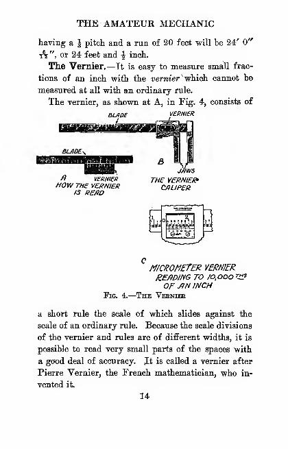
The Vernier.—It is easy to measure small frac-
tions of an inch with the uermer^which cannot be
measured at all with an ordinary rule.
The vernier, as shown at A, in Fig. 4, consists of
BUIDE VERNIER
/? YERHIERHOW THE VERNIER
IS REfiO
BMws
THE Y£RN/£/<»CJILIPER
Fig. 4.-
micrometer vernierREflDING TO /o.oooVi?OF -AN INCH
-The Veeniie
a short rule the scale of which slides against the
scale of an ordinary rule. Because the scale divisions
of the vernier and rules are of difFerent widths, it is
possible to read very small parts of the spaces with
a good deal of accuracy. Jt is called a vernier after
Pierre Vernier, the French mathematician, who in-
vented it.
14
RULES AND TOOLS FOR MEASURING
The principle on whicli the vernier works is this
:
First the scale of the ordinary rule is divided, let's
say, into lOths of an inch, and that the vernier is 1
inch long and is divided into 9ths of an inch—that
is, it has one less scale division or space to the
inch than the rule it slides against.
Now when the end lines of both the scales of the
vernier and the rule meet, that is, when they are in
a line with each other, the 10th line on the vernier
will exactly coincide with the 9th line on the rule.
If, now, you slide the vernier toward the right
so that the first lines on the vernier and rule meet,
the vernier will have moved exactly tV of a scale
division or space, which is t^ of an inch, for this is
the difference between the two scales. By sliding
the vernier over until the second lines meet, it will
have moved 1% of a scale division, or t^t of an incl •
or 3V of an inch, and so on. Verniers are put ol
and used with various measuring tools, such as
calipers, protractors, etc.
The Vernier Caliper.—The vernier caliper
shown at B is made to take inside as well as out-
side measurements. It is graduated on the front to
read, by means of the vernier, to lOOOths of an inch
and on the back to 64th3 of an inch.
How to Bead a Vernier Caliper.—There are three
chief makes of vernier calipers, and these are (1)
the Brown and Sharp, (2) the Starrett and (3)
the Columbia Pattern.
On either of the first two makes of calipers the
15
THE AMATEUR MECHANIC
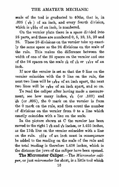
scale of the tool is graduated to 40ths, that is, in
.025 ( iV ) of an inch, and every fourth division,
which is tMt of an inch, is numhered.
On the vernier plate there is a space divided into
25 parts, and these are numbered 0, 5, 10, 15, 20 and
25. These 25 divisions on the vernier take up exact-
ly the same space as the 24 divisions on the scale of
the rule. This makes the difference between the
width of one of the 25 spaces on the vernier and one
of the 24 spaces on the scale -^ of A or ttJW of an
inch.
If now the vernier is set so that the line on the
vernier coincides with the line on the rule, the
next two lines will be tijVt of an inch apart, the next
two lines will be xuVir of an inch apart, and so on.
To read the caliper after having made a measure-
ment, see how many inches, ^ (or .100) and
"A (or .025), the mark on the vernier is from
the mark on the rule, and then count the number
of divisions on the vernier from to a line which
exactly coincides with a line on the scale.
In the picture shown at C the vernier has been
moved to the right 1 1\ and ^V inches, or 1.425 inches,
as the 11th line on the vernier coincides with a line
on the rule, riiv of an inch must in consequence
be added to the reading on the scale of the rule and
the total reading is therefore 1.436 inches, which is
the distance the jaws of the caliper have been opened.
The Micrometer Caliper.—The Micrometer cali-
per, or just micrometer for short, is a little tool which
16
RULES AND TOOLS FOR MEASURING
•will measure very accurately from to 1 inch im
thousandths or even ten-thousandths of an inch.
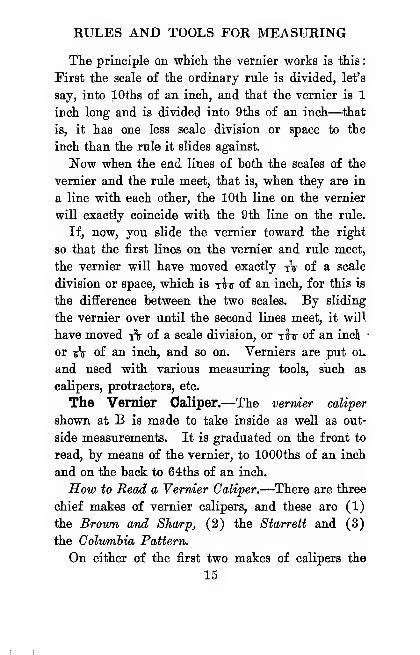
A micrometer is formed of (1) a frame to which is
fixed (2) the anvil and through which (3) the spindle
passes; the spindle is fastened to (4) the thimble
and these turn in (5) the sleeve^ as shown at A in
Fig. 5.
How to Bead a Micrometer.—To measure the
thickness of a sheet of paper or anything else, put
it hetween the anvil and the end of the spindle and
hold the frame with your left hand. Now turn the
thimble with your right hand and since the spindle
is fixed to the thimble it of course turns with it.
This makes it move through the nut in the frame
and toward or away from the anvil.
The distance between the opposed surfaces of the
anvil and the spindle is shown by the lines and figures
on the sleeve and the thimble, and these tell the thick-
ness of the thing you have measured.
The pitch of the screw threads on the inside part
of tl^e spindle which screws through the nut, is 40
to the inch ; one complete turn of the spindle, there-
fore, moves it up or down -^ij, or ilfir, of an inch.
The sleeve is marked with 40 lines to the inch and
these correspond to the number of threads on the
spindle.
When the end of the spindle rests on the anvil the
graduated edge of the thimble is exactly even with the
line marked on the sleeve and the line on the
thimble tallies with the horizontal line on the sleeve.
17
THE AMATEUR MECHANIC
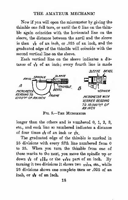
Now if you will open the micrometer by giving the
thimble one full turn, or until the line on the thim-
ble again coincides with the horizontal line on the
sleeve, the distance between the anvil and the sleeve
is then :iV of an inch, or .025 of an inch, and the
graduated edge of the thimble will coincide with the
second vertical line on the sleeve.
Each vertical line on the sleeve indicates a dis-
tance of iV of an inch; every fourth line is made
SLEEVE BEVEL
/fNYlLSPINDLE SLeEVe
/)
/f/CfipMET£^l?E/)DING70 — FRAME/.OOOV^ OF/IN/NCH
THIMBLEBEVEL VERNIEU
Fig. 5.-
MICROMETER WITH
VERNIER READINGTO /o.ooor»s OFAN INCH
The MiCEiOMETBB
longer than the others and is numbered 0, 1, 2, 3,
etc., and each line so numbered indicates a distance
of four times iV of an inch or tV,
The graduated edge of the thimble is marked in
25 divisions with every fifth line numbered from
to 25. When you turn the thimble from one of
these marks to the next, you move the spindle up or
down A of iMt or the ttVtt part of an inch. Byturning it two divisions it shows two nrVir, etc., while
25 divisions shows one complete turn or .025 of an
inch, or A of an inch.
18
RULES AND TOOLS FOR MEASURING
All you have to -(10 to read the micrometer, then,
is to multiply the number of vertical divisions vs^hich
you can see on the sleeve by 25 and all the number
of divisions on the graduated edge of the thimble
from the line to the line which tallies with the
horizontal line on the sleeve; multiply this number
by 25 and add the number of divisions shown on the
<B)=^^
^L£V£L WJTH PWNB Gl/FSSy?r £/7C// £AfD
/ALCOHOL CENTER.BUBBLE^ GLfiS-S
TUBE
Pli//^S GJUJSS /IJfRKED /}T ITSCENTER OR CROWN/NG PO//^TMYTWO UNE%
Pig. 6.—A Level and Its Plumb Glass
bevel of the thimble. In the cut shown at A the
micrometer is open 7 X 25 = 175 -(- 3 = 178 or
tWo of an inch.
A Micrometer Reading to Ten-Thoicsandths.—^A
vernier is used on a micrometer, see B, in order to
read it to tttAttt of an inch. To read a tt.Vttt
micrometer, first find the thousandths of an inch as
described above, and then note the line on the thimble.
If it is the second line, marked 1, add T^r.^inr; if it
is the third line, marked 2, add tttjW, etc.
19
THE AMATEUR MECHANIC
Gauges for Testing and Comparing.—Gaugesfor every purpose to facilitate or to make more accu-
rate the work of the mechanic can be bought at almost
any hardware store. If you cannot get what you
want, write Hammacher, Schlemmer & Co., Fourth
Avenue and 13th Street, "New York, and they will
most likely be able to supply you with the tool you
need.
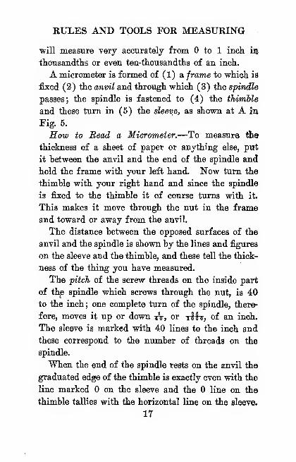
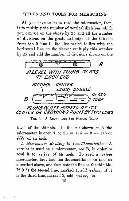
One of the most common and useful gauges is the
carpenter's or mason's level, shown at A in Fig. 6.
When you are putting in a foundation for either a
building or for machinery, the first thing to do is to
find whether the top of it is level. This is done with
a level ; and to ascertain whether the side of the wall
is plumb, an upright level, or plumb, must be used.
A spirit level consists of a sealed glass tube nearly
filled with alcohol and having a bubble floating in
it, as shown afr B. This plumb glass, as it is called,
is set in a stock, or length of wood, when the whole
device is called a level. When the level is laid on
a level surface the bubble will be in the middle of
the glass, but if the surface is not level the bubble
will flow to one end or the other to indicate it.
Levels are usually made with two plumb glasses,
one in the upper edge and one in the top of and at
right angles to it, so that it can be used to find if
the side of a wall, as well as the top of it, is level.
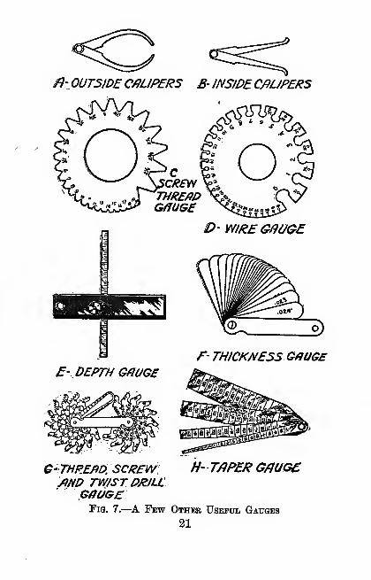
A few of the more common gauges used by machinists
are shown in Fig. 7.
The Protractor.—To find any angle or to plot one
20
/}'0UT5/D£ C/?UPER5 B- JNSJDECfiUPERS
CCREW
THREADGfilUGE
mit^
F- THICKNESS GflUGE
E- DEPTH GflUGE
c-iTHREAD, screw: H- t/iper g/iugc/)HD TW/STDR/U
GffaesTig. 7.—^A Few Other Useful Gauges
21
THE AMATEUR MECHANIC
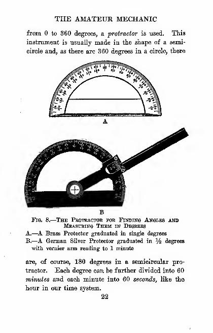
from to 360 degrees, a protractor is used. This
instrument is usually made in the shape of a semi-
circle and, as there are 360 degrees in a circle, there
Fig. 8.
—
The Protractor tor Finding Angles aotj
Measuring Them in Degrees
A.—A Brass Protector graduated in single degrees
B.—A German Silver Protector graduated in % degrees
with vernier arm reading to 1 minute
are, of course, 180 degrees in a semicircular pro-
tractor. Each degree can be further divided into 60
minutes and each minute into 60 seconds, like the
hour in our time system.
22
RULES AND TOOLS FOR MEASURING
A brass protractor 3J inches in diameter can be
bought " for as little as 25 cents. One of this kind
is shown at A in Fig. 8. For all ordinary work
scale divisions of 1 degree, or ^ degree, will be found
close enough; but where readings to minutes are
needed a vernier protractor, as shown at B, must be
used.
To use an ordinary protractor, place it on a sheet
POi£
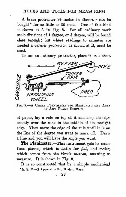
O WHEELFig. 9.—^A Cheap Planimeter for Measuring the Area
OP Ant Plane Surface
of paper, lay a rule on top of it and keep its edge
exactly over the nick in the middle of its straight
edge. Then move the edge of the rule until it is on
the line of the degree you want to mark off. Drawa line and you will have the angle you want.
The Planimeter.—This instrument gets its namefrom planus, which is Latin for flat, and meter,
which comes from the Greek metron, meaning to
measure. It is shown in Fig. 9.
It is so constructed that by a simple mechanical
*li. E. Knott Apparatus Co., Boston, Mass.
- 23
THE AMATEUR MECHANIC
operation the area of any flat figure, however irregu-
lar the boundary line of it may be and drawn to what-
ever scale, such as a plot of ground, plans, indicator
diagrams, etc., can be easily and quickly measured.
The area of the plane figure is measured by mere-
ly tracing the outline with the tracing point and
figuring the result from the reading on the graduated
wheel. This wheel is divided into 100 parts, each
of which represents tV of a square inch, and each
10th can be read down to lOOths by the vernier on
the instrument.
The simplest and cheapest planimeter measures up
to 10 square inches and costs about $15. It can be
bought of Keuffel and Esser, 101 Fulton Street, NewYork, or of Hhs L. E. Knott Apparatus Gomparuf,
Boston, Mass.
CHAPTEK II
WHEN YOU BUILD YOUR HOUSE
You will find it a money saving deal to know
something about building materials and how to choose
and use them before you start in to build a house,
or even a chicken coop.
Without such a working knowledge it is easy to
pay high prices for poor grades and to use costly
materials where cheaper kinds will do just as well.
This is equally true whether you are going to do
the job yourself or to hire someone to do it for you.
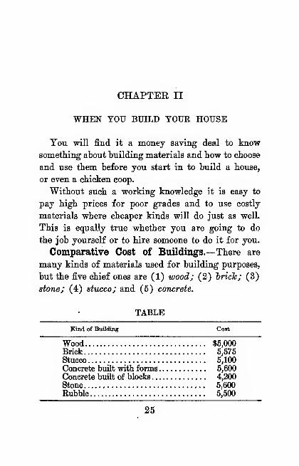
Comparative Cost of Buildings.—There are
many kinds of materials used for building purposes,
but the five chief ones are (1) wood; (2) hrich; (3)
stone; (4) stucco; and (5) concrete.
TABLE
Kind of Buildine Coat
Wood $5,000Brick 6,575Stucco 5,100Concrete bmlt with forms 5,600Concrete built of blocks 4,200Stone 5,600Rubble 5,500
25
THE AMATEUR MECHANIC
The comparative cost of buildings in -which these
materials are used varies in different localities, hut
the above table will serve to shov7 them approxi-
mately.
Kinds of Materials to Use.—Where ordinary-
buildings are put up, the piling, if it is used, can be
of wood or concrete. For basement walls to the first
floor level, plank, brick, rubble, stone, concrete or
hollow tile can be used.
, Walls are built of wood, brick, stone, stucco, con-
crete, and occasionally of tile. Chimneys can be
laid up of brick or built of concrete. All kinds of
material, such as wood, asphalt and asbestos shingles,
tin, galvanized iron, copper and zinc, slate and tile,
are used for roofing.
Floors can be made of wood, concrete, tile, mosaic,
rubber or pulp. The outside trim, such as doors and
finish, windows and finish, pillars and turned work
in general, and the inside finish, such as stairs, rail-
ings, ceiling beams, mantels, paneling, etc., all come
under the head of mill work and can be bought ready
made cheaper than you or a carpenter could possibly
make them. They are far better, too, when bought.
Builders' hardware includes all kinds of hardware
used on a building, and, finally, for plastering, wood
and metal lath are used.
Now about Lumber.— TTAen the Tree is Felled.
—The word timber is used to mean both growing trees
and cut trees and squared and sawed wood of the
larger sizes, while the word lumber is taken to mean
26
WHEN YOU BUILD YOUR HOUSE
timber whicli has been sawed into scantlings and
boards.
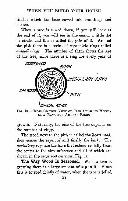
When a tree is sawed down, if you will look at
the end of it, yon will see in the center a little dot
or circle, and this is called the pith of it. Around
the pith there is a series of concentric rings called
annual rings. The number of them shows the age
of the tree, since there is a ring for every year of
HEflRTWOODB/?RKJ
SfiPWOOH
'5DULLARY R/fYS
P/TH
'/f/VNU/iL RINGS
Fig. 10.
—
Ceoss Section View of Tree Showing Medul-lary Rats and Annual Eings
growth. Naturally, the size of the tree depends on
the number of rings.
The wood next to the pith is called the Jieartwood,
then comes the sapwood and finally the hark. The
medullary rays are the lines that extend radially from
the center to the circumference and all of which are
shown in the cross section view, Fig. 10.
The Way Wood Is Seasoned.—When a tree is
growing there is a large amount of sap in it. Since
this is formed chiefly of water, when the tree is felled
27
THE AMATEUR MECHANIC
the water still remains in it. Before it can be used
for building, the water must be dried out of it to
some extent, and this process is called seasoning.
The two usual ways of getting rid of the water
are by (1) natural seasoning and (2) hot air season-
ing. If after the rough work has been done on a
building it is left for a while before finishing, it
dries out still more, and this is called second seo/-
soning.
Natural Seasoning.—The natural way of season-
ing lumber is the best way, but it takes a long time.
It is done by piling it up so that the air can pass
freely all around each piece. When you buy lum-
ber for outside use, be sure to get it seasoned by this
process.
Hot Air Seasoning.—This is the artificial method
and, while it is quickly done, it is not nearly as good
as natural seasoning. It consists of putting the lum-
ber in a drying roorrij that is, a room which is kept
hot by means of steam pipes. Wood seasoned in
this way is very apt to shrink or swell with the
changes of the weather. Hence it should never be
used except for inside work.
How to Tell Good Lumber.—Trees have their
diseases and parasites as well as human beings and
in buying lumber, as in every day life, you must look
out for them.
Lumber for building should be straight grained,
be clear, that is, without knots, and be free from
sap. You can always tell good lumber by its sweet
28
WHEN YOU BUILD YOUR HOUSE
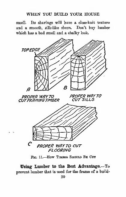
smell. Its shavings will have a dose-knit texture
and a smooth, silk-like sheen. Don't buy lumber
which has a bad smeU and a chalky look.
TOP£DGE
PROPER VMYTOCUTFRAMING TIMBER
PROPER W/tY TOCUT SILLS
PROPER W/}YTO CUT/=LOORING
Fig. 11.—How Toibeb Should Bb Cut
Using Lumber to the Best Advantage.—To
prevent lumber that is used for the frame of a build-
29
THE AMATEUR MECHANIC
ing from shrinting, it should he cut so tliat the an-
nual rings run in the same direction as the long end
of the board, as shown at A in Fig. 11.
Where beams are used for sills, as the horizontal
members which form the foundation of the building
are called and on which the weight of the building
rests, the beam will be stronger if it is laid with the
annual' rings horizontal, as shown at B. Flooring
is less apt to shrink and will wear better if you can
get it so that its annual rings are perpendicular to
the surface, as shown at C.
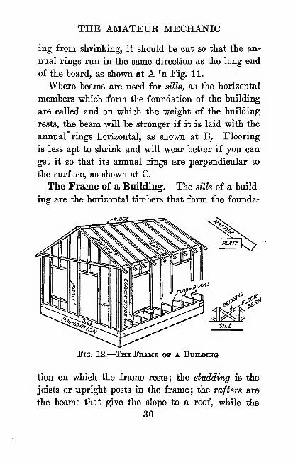
The Frame of a Building.—The sills of a build-
ing are the horizontal timbers that form the founda-
^«">
Fig. 12.
—
The Frame of a BunDiNG
tion on which the frame rests; the studding is the
joists or upright posts in the frame; the rafters are
the beams that give the slope to a roof, while the
30
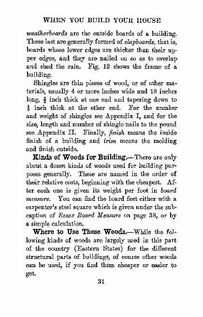
WHEN YOU BUILD YOUR HOUSE
weatherboards are the outside boards of a building.
These last are generally formed of clapboards, that is,
boards whose lower edges are thicker than their up-
per edges, and they are nailed on so as to overlap
and shed the rain. Tig. 12 shows the frame of a
building.
Shingles are thin pieces of wood, or of other ma-terials, usually 4 or more inches wide and 18 inches
long, J inch thick at one end and tapering down to
^ inch thick at the other end. For the number
and weight of shingles see Appendix I, and for the
size, length and number of shingle nails to the pound
see Appendix II. Finally, finish means the inside
finish of a building and trim means the molding
and finish outside.
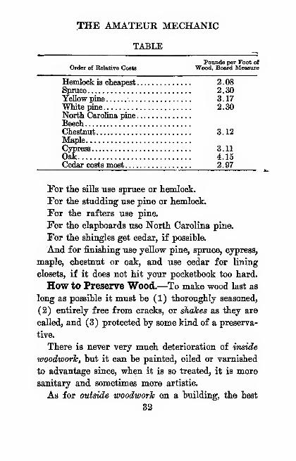
Kinds of Woods for Building.—There are only
about a dozen kinds of woods used for building pur-
poses generally. These are named in the order of
their relative costs, beginning with the cheapest Af-
ter each one is given its weight per foot in hoard
measure. You can find the board feet either with a
carpenter's steel square which is given under the sub-
caption of Essex Board Measure on page 38, or by
a simple calculation.
Where to Us© These Woods.—While the fol-
lowing kinds of woods are largely used in this part
of the country (Eastern States) for the different
structural parts of buildings, of course other woods
can be used, if you find them cheaper or easier to
get.
31
THE AMATEUR MECHANIC
TABLE
Pounds per Foot ofOrder of Relative Coeta Wood, Board Measure
Hemlock is cheapest 2.08Spruce 2.30Yellow pine 3. 17White pine. 2.30North Caxolina pineBeechChestnut 3.12MapleCypress 3.11Oak 4.15Cedar costs most 2.97
For the sills use spruce or hemlock.
For the studding use pine or hemlock.
For the rafters use pine.
For the clapboards use North Carolina pine.
For the shingles get cedar, if possible.
And for finishing use yellow pine, spruce, cypress,
maple, chestnut or oak, and use cedar for lining
closets, if it does not hit your pocketbook too hard.
How to Preserve Wood.—To make wood last as
long as possible it must be (1) thoroughly seasoned,
(2) entirely free from cracks, or shakes as they are
called, and (3) protected by some kind of a preserva-
tive.
There is never very much deterioration of inside
woodwork, but it can be painted, oiled or varnished
to advantage since, when it is so treated, it is more
sanitary and sometimes more artistic.
As for outside woodwork on a building, the best
32
WHEN YOU BUILD YOUR HOUSE
way to preserve it is to paint it. The best kind of
paint is made of pure white lead and boiled linseed
oil. Where wood is to be set in the ground, as
posts, piles and flag poles, the ends can be tarred,
charred or creosoted. ^ Tarring and creosoting are
simple processes, for the wood needs only to be dipped
into the former and soaked in the latter while it is
hot. Charring is done by covering the end of the
wood with charcoal and burning it.
Bricks and Brickwork.—^A brick is a piece of
molded clay which is dried in the sun and then
burned in a kiln. Bricks come in two colors, red
and white. The color of red bricks is caused by iron
compounds in the clay, while light-colored bricks are
made from clay which is practically free from iron.
Kinds of Bricks.—^Bricks can be divided into two
general classes, and these are (1) stoch or hiln-run
bricks, which are hard enough for the outside of
buildings, and (2) soft or salmon bricks, which are
used only for backing up and filling in.
There are a dozen grades of brick of the first kind
and among these are (a) common molded, (b)
pressed and (c) enameled bricks. There are half
a dozen grades of the second kind and among these
are common, soft and salmon brick.
The size of a standard brick in the United States
is 2 X 4 X 8i inches and its weight is about 4t\ pounds.
•For wood preservatives write the CarbolineiMn Wood Pre-
serving Co., 36 Greene Street, New York, or the Lyster Chemical
Co., 61 Broadway, New York.,
33
THE AMATEUR MECHANIC
There are 66 cubic inches in a brick and, hence, it
takes 26.2 bricks to make a cubic foot.
Bricks are very porous. A conunon brick will
absorb as much as ^ of its weight of water; but a
really good brick should not absorb more thair tV
of its weight of water. To test a brick for porosity,
weigh it, then let it soak in water over night and
weigh it again. The difference in the weights wiU
give the weight of the water absorbed.
Mortar for BrickworTe.—In laying up a brick wall
or chimney, the bricks are held together with a ce-
ment called mortar, which is made of slaked lime and
sand.
Lime, or more properly quicklims, is a substance
whose chemical name is calcium, oxide. When it is
mixed with water it generates a lot of heat and
changes into calcium hydroxide. This process is
known as slaking.
Sand is then mixed with it and the mortar thus
made slowly absorbs carton dioxide from the air
which, acting on the calcium, hydroxide, forms cal-
cium, carbonate, or limestone, and when the water
dries out it becomes very hard. The purpose of the
sand is to make the mortar porous so that the carbon
dioxide can mix with it and it also prevents the mor-
tar from cracking when it gets hard.
Plaster for Walls.—Plaster is simply mortar.
Three different kinds of it are used for walls, and
these are (1) coarse stuff, (2) fine stuff and (3)
gauged stuff.
Si
WHEN YOU BUILD YOUR HOUSE
Coarse staff is common mortar with liair mixed
in it to bind it together. It is formed of 6 parts of
lime, 12 of sand and 1 of hair. It is the first coat
of plaster put on the lath, and the plasterer calls this
rendering.
Fine stuff is made by mixing lime with water until
it is about as thick as cream. After it has settled,
the water is drained off. When the lime paste has
hardened a little, a very small quantity of sand is
mixed with it; it is then put over the coarse stuff,
and this is called floating.
Gauged stuff is made by miTn'rig 1 part of plaster
of Paris with 4 parts of fine stuff. The plaster of
Paris makes the stuff set very quickly, and so no
more must be mixed at a time than you can put on
before it gets hard. It is plastered over the fine stuff
and is the last coat, or finish, and is called setting.
About Layingf Brick.—^In bricklaying a course is
a continuous layer of bricks in a horizontal line, and
a bond means the method used in laying the bricks
in courses.
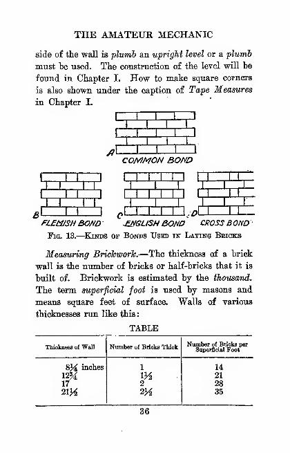
There are four chief bonds used in building brick
structures, and these are (1) common bond, (2)
Flemish bond, (3) English bond and (4) cross bond,
all of which are shown in Fig. 13.
When you lay up a brick wall, the first thing to
do is to have the foundation on which the courses are
laid perfectly level. To find whether the top surface
of the foundation and of the wall as you lay it are
level, you must use a level, and to ascertain if the
35
THE AMATEUR MECHANIC
side of the wall is plumb an upright level or a plumb
must be used. The construction of the level will be
found in Chapter I. How to make square corners
is also shown under the caption of Tape Measures
in Chapter I.
COMMON BOND
'^°?=? °̂ ^^.DV
I. I I. I
fLEtUSH BOND -ENGLISH BOND CROSS B OND'
Fig. 13.
—
Kinds of Bonds Used in Laying Beicks
Measuring BrickworTe.—The thickness of a brick
wall is the number of bricks or half-bricks that it is
"built of. Brickwork is estimated by the thousand.
The term superficial foot is used by masons and
means square feet of surface. Walls of various
thicknesses run like this:
TABLE
Thickness of Wall
WHEN YOU BUILD YOUR HOUSE
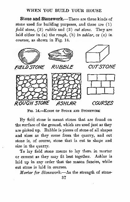
Stone and Stonework.—There are three kinds of
stone used for building purposes, and these are (1)
field stone, (2) rubhle and (3) cut stone. They are
laid either in (a) the rough, (b) in ashlar, or (c) in
courses, as shown in Fig. 14.
FJELDSTONE RUBBLE CLfTSTOfiE
ROUGH STONE fiSHUiR COURSES
Fie. 14.—^KiNDS OF Stone and Stonework
By field stone is meant stones that are found on
the surface of the ground, which are used just as they
are picked up. Eubble is pieces of stone of all shapes
and sizes as they come from the quarry, and cut
stone is, of course, stone that is cut to shape and
size in the quarry.
To lay field stone means to lay them in mortar
or cement as they may fit best together. Ashlar is
laid up in any order that the mason fancies, while
cut stone is laid in courses.
Mortar for Stoneworh.—As the strength of stone-
37
THE AMATEUR MECHANIC
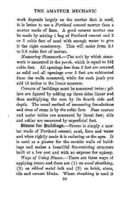
vrork depends largely on the mortar that is used,
it is better to use a Portland cement mortar than a
mortar made of lime. A good cement mortar can
be made by mixing 1 bag of Portland cement and 2
or 3 cubic feet of sand with enough water to give
it the right consistency. This will make from 2,1
to 2.8 cubic feet of mortar.
Measuring Stonework.—The unit by which stone-
work is measured is the perch, which is equal to 241
cubic feet. All openings less than 3 feet are counted
as solid and all openings over 3 feet are subtracted
from the walls measured, while for each jamb you
add 18 inches to the linear measure.
Comers of buildings must be measured twice;pil-
lars are figured by adding up three sides linear and
then multiplying the sum by its fourth side and
depth. The usual method of measuring foundations
and sizes of stone is by the cubic foot. Base courses
and water tables are measured by lineal feet; siUs
and ashlar are measured by superficial feet.
Stucco for Buildings.—Stucco is simply a mor-
tar made of Portland cement, sand, lime and water
and when rightly made it is enduring as the ages. It
is used as a plaster for the outside walls of build-
ings and makes a beautiful fire-resisting structure
built at a low cost and with no expense for upkeep.
Ways of Using Stucco.—There are three ways of
applying stucco and these are (1) on wood sheathing,
(2) on rihied metal lath and (3) on brick, stone,
tile and cement blocks. Where sheathing is used it
38
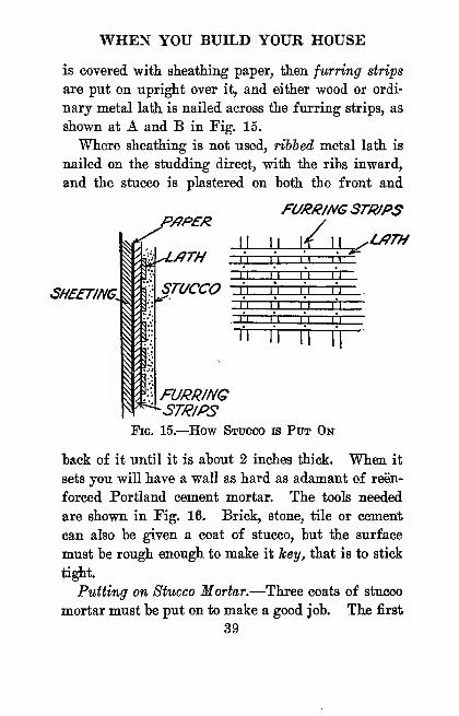
WHEN YOU BUILD YOUR HOUSE
is covered with, sheatiiing paper, tlien furring strips
are put on -upright over it, and either wood or ordi-
nary metal lath is nailed across the furring strips, as
shown at A and B in Fig. 15.
Where sheathing is not used, ribbed metal lath is
nailed on the studding direct, with the ribs inward,
and the stucco is plastered on both the front and
^A5Sf77ACL I ^
fc^'"
PJ7P£fZFUJ?R/f^G3TR/PS
ZSTUCCO 3 EZZI
1—
r
\^UyTH
\\\\
FURRING'STR/PS
Fig. 15.—How Stucco is Put On
back of it until it is about 2 inches thick. When it
sets you will have a wall as hard as adamant of reen-
forced Portland cement mortar. The tools needed
are shown in Fig. 16. Brick, stone, tile or cement
can also be given a coat of stucco, but the surface
must be rough enough to make it hey, that is to stick
tight.
Putting on Stucco Mortar.—Three coats of stucco
mortar must be put on to make a good job. The first
39

THE AMATEUR MECHANIC
coat, which, is put on the face of the lath, and the
second coat, which is put on the back of the lath,
should each be f inch thick, while the last and finish-
ing coat should be J inch thick.
When stucco is put on ribbed lath, the first front
and back coats should be from f to J inch thick, and
the finish coat J inch thick.
How to Make Stucco Mortar.—For the first two
coats of stucco mix 3 parts of sand with 1 part of
Portland cement by volume. For the finish coat
mix 2i parts of sand with 1 part of Portland cement
and tV part of lime.
Use a water-tight platform to mix the stucco on
so that, after you have the right amount of water
for mixing, it wiU not leak away. Sometimes hair
or fiber is used for the first coat of stucco, as in
ordinary mortar. If either is used, it is mixed in
after the mortar is made. Mix the mortar until it
is smooth and is of the same color throughout.^
Building with Concrete.— Concrete is your
building material, by which I mean that you can
build any ordinary structure of it with the help of
common labor.
It is timeproof, waterproof and fireproof and,
though it costs a little more than wood in the first
place, it does not cost anything for paint and re-
pairs after it is built. It is. different from brick
"If you are interested in building a stucco home, a garage
or a barn, write the Atlas Portland Cement Co., 30 BroadStreet, New York, and they will send you plans and specifica-
tions without cost.
40

WHEN YOU BUILD YOUR HOUSE
and stone in that you can always get the materials
to make concrete •wherever you live.
What Concrete Is.—Concrete is made up of four
materials and these are (1) Portland cement, (2)
sand, (3) stone or gravel and (4) water. It is called
Portland cement hecause it is about the same color
as the limestone quarried on the Isle of Portland,
England.
It is made by heating limestone, clay and sand, or
blast furnace slag, until they are changed into a
powder and when this is mixed with water it wiU
set hard and water will not affect it in any way.
Portland cement is manufactured in great mills
where it is packed in bags which hold about 1 cubic
foot each. It is then shipped to the four quarters
of the globe, so you will have no trouble in buying
it wherever you are.
Materials for Concrete.—Testing Portland Ce-
ment.—^Before the cement is used it must be kept
perfectly dry or it will absorb moisture and get hard.
Sometimes when bags of cement are piled on each
other, the cement will caJce, but this does not injure
it in any way. To test cement that is lumpy, pinch
a piece of it between your fingers and see if it will
break up ; if it will not, it is useless for concrete.
Testing Sand.—Sand, or fine aggregate, as it is
called, must not have any loam, clay or other impuri-
ties in it. The particles that form it must not be
too large to pass through a sieve with f inch meshes.
To test sand for impurities, take a little while it
41

THE AMATEUR MECHANIC
is still moist from where it is dug and rub it between
the palms of your hands. If it does not soil them it
is free enough from loam to use, but if it does, it
must be washed by shoveling it onto a screen and
washing it down with water.
Crushed Stone or Gravel.—^Either gravel or
crushed stone, or coarse aggregate, as it is called,
can be used for concrete. It must be clean, free
from impurities, and should not be less than \ inch
in size and never more than half the thickness of
the concrete you are placing. Finally, well water
is the best kind to use for making concrete.
Mixtures of Concrete and Where to Use Them.—The following mixtures are largely used and will
give satisfaction for the purposes named.
A Rich Mixture.—^Use 1 part of cement, Ij parts
of sand and 3 parts of coarse aggregate; this makes
a good cement for waterproof buildings and roads.
The Standard Mixture.—^Use 1 part of cement, 2
parts of sand and 4 parts of coarse aggregate. Use-
ful for floors, roofs, tanks, conduits, sewers and reen-
forced work.
A Medium Mixture.—^Use 1 part of cement, 2\
parts of sand and 5 parts of coarse aggregate. Large-
ly used for foundations, piers, walls, etc
A Lean Mixture.—^Use 1 part of cement, 3 parts
of sand and 6 parts of coarse aggregate. Good for
backing stone masonry, massive concrete work and
large foundations.
« .Mixing Concrete.—The materials of which con-
42
WHEN YOU BUILD YOUR HOUSE
Crete is made can he mixed either (1) by hand, or
(2) by machine. It should be mixed close to the
place where you are going to use it ; otherwise it will
set before you can place it. For ordinary work it
should be about as thick as jelly, and it should be
mixed just as mortar is.
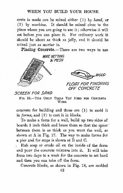
Placing Concrete.—There are two ways to use
WIRE NETTING
'AMESH
WOOD
FLO/?TFOR FINISHING
OFF CONCRETESCREEN FOR S/tND
Fig. 16.
—
The Only Tools You Need foe ConcreteWork
concrete for building and these are (1) to mold it
in forms, and (2) to cast it in blocks.
To make a form for a wall, build up two sides of
boards 1 inch thick and brace them so that the space
'
between them is as thick as you want the wall, as
shown at A in Fig. 17. The way to make forms for
a pier and for steps is shown at B and C.
IHub soap or crude oil on the inside of the form
and pour the concrete mixture into it. It will take
from two days to a week for the concrete to set hard
and then you can take off the form.
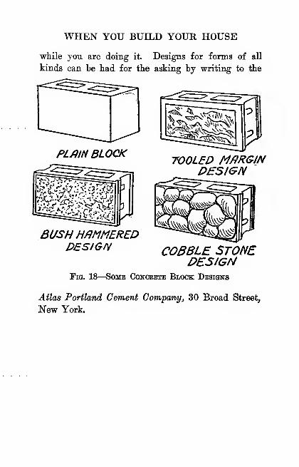
Concrete blocks, as shown in Fig. 18, are molded
43

THE AMATEUR MECHANIC
either hollow or in solid veneer and they are easy to
make and set. If you are interested in building with
them, write to the Ideal Concrete Machinery Comr
pany of South Bend, Indiana, for a free booklet of
their machines and equipment.
FORMFOR MAKINGDUPLICmEfiERS
FORMSFOR nmiNG)'-
fi W/ILL
Fig. 17.-
FORMS FORCONCRETFSTEPS
Forms foe Placing Concbete
Finishing Concrete Surfaces.—Ordinary con-
crete work does not have to be finished, but you can
improve the surfaces of walls by rubbing them with a
cement mortar hrich, made of 1 part of cement and
2 parts of sand, and keeping it flushed with water
44
WHEN YOU BUILD YOUR HOUSE
while you are doing it. Designs for forms of all
kinds can be had for the asking by writing to the
PL/}IN BLOCKTOOLED M/iRGIN
DESIGN
BUSH H/)MMEREPDESIGN COBBLE STONE
DESIGNFig. 18
—
Some Concrete Block Designs
Atlas Portland Cement Company, 30 Broad Street,
New YorL
CHAPTEE III
A WATER SYSTEM FOR YOUR PLACE
In these days of power and pumps, the scsheme of
carrying water from a well to supply the kitchen and
of taking a bath in a washtub on Saturday night is
as out-of-date and about twice as barbarous as cook-
ing in a fireplace.
But however or wherever the water comes from,
disease germs are more than likely to be carried by
it, and as it is your first duty to safeguard the health
of your home you must know to a certainty that the
water supply is absolutely pure.
Kinds of Water Supplies.—There are three
kinds of water supplies, or places from which to get
water, and these are (1) surface, (2) shallow under-
ground and (3) deep underground supplies.
The surface supplies are the ponds, streams, rivers
and cisterns and all , of these are very apt to be
polluted with disease germs. This untoward con-
dition is largely due to contamination from sewage,
that is, the sewage is either emptied into them or
else seeps into them from nearby sources. What-
ever you do, don't use water from a surface supply
46
A WATER SYSTEM FOR YOUR PLACE
for driiiking, or cooking, or even washing dishes,
unless it has been thoroughly purified first.
The water of shallow wells is also often disease
hearing, hut deep wells are very seldom so. In any
event, remember that water which looks perfectly
clear may have disease germs in it.
How to Purify Water.—By Boiling.—^A simple
and sure way to get rid of all the germs in water is
to boil it; but it is not enough to merely bring the
water to a boil, for a typhoid germ is as immune to
heat as an asbestos cat. Boiling the water for 15
minutes or so will kill most of the germs, but to be
sure .that all of them are killed the water must be
boiled twice.
By Filtration.—A great deal of impure matter in
water can be removed from it by filtering, that is,
by straining it through some kind of porous material.
Filters that are made to screw on to the faucet re-
move some of the impurities, but most of the germs
go on through.
Filters made of charcoal, sand and gravel •" remove
nearly all the impurities, but still some of the germs
get through. By adding a very small amount of
alum to the water the impurities and nearly all the
germs will stick to the particles of it which then
fall to the bottom, or are precipitated, as it is called.
' A complete description of a cheap and good filter of this
kind, with drawings, is given in my "Home Handy Book,"published by D. Appleton and Company, New York.
47

THE'AMATEUR MECHANIC
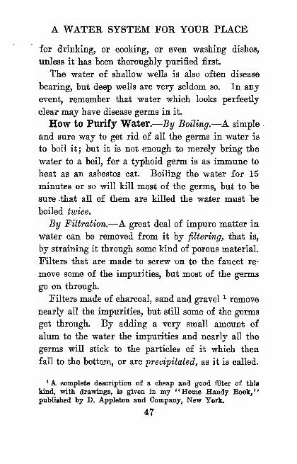
The Pasteur filter ^ is a good one for the house-
hold. The water flows in through the top and its
"weight forces it through an unglazed porcelain
cylinder, the top end of which is closed. To makethe filter effective the cylinder must be taken out
W/JT£R INLET
UNGLfiZEPPORCEUillCYUNPER
STBELCYUNDER)
^OUTLET
Fig. 19.
—
The Pasteub Water Filteb
every day and the mud and slime scrubbed off with
a brush. Otherwise it will form a breeding place
for the germs instead of purifying the water. It
is shown in Fig. 19.
By Distillation.—To distill water on a large scale
' Sold by the Consolidated Filters Co., 136 West 65th Street,
New York.
48
A WATER SYSTEM FOR YOUR PLACE
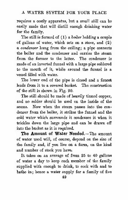
requires a costly apparatus, but a small still can be
easily made tbat will distill enougb drinking water
for the family.
The still is formed of (1) a boiler Holding a couple
of gallons of water, whicb sets on a stove, and (2)
a condenser bung from the ceiling; a pipe connects
the boiler and the condenser and carries the steam
from the former to the latter. The condenser is
made of an inverted funnel with a large pipe soldered
to the mouth of it, while around the funnel is a
vessel filled with water.
The lower end of the pipe is closed and a faucet
leads from it to a covered bucket. The construction
of the still is shown in Fig. 20.
The still should be made of heavily tinned copper,
and no solder should be used on the inside of the
seams. Now when the steam passes into the con-
denser from the boiler, it strikes the funnel and the
cold water which surrounds it condenses it when it
trickles down the large pipe and can be drawn off
into the bucket as it is required.
The Amount of Water Needed.—The amount
of water used will, of course, depend on the size of
the family and, if you live on a farm, on the kind
and number of stock you have.
It takes on an average of from 25 to 40 gallons
of water a day to keep each member of the family
supplied with enough to drink, to cook with and to
bathe in; hence a water supply for a family of five
49

COVER . J^J/^ V^NT
COOLING W/9T£R
COLLECTOR
CONDENSER^
STE/lMPJPf
A,v^PlSriLLEP^^ W/fTER s
FILLER
Aif.^
BOILER
BUCKET[r~[ STOVE
ffFig. 20.—^A Home-made Water Distilling Appabatus
50
A WATER SYSTEM FOR YOUR PLACE
or six should liave a tank, if one is used, witli a
capacity of something over 200 gallons.
Where there is stock, each cow needs about 12
gallons ; each horse about 10 gallons ; each hog about
2i gallons; each sheep about 2 gallons, and there
must be a small surplus for the dog and the cat. If
you intend to sprinkle the lawn and the garden and
have fire protection, allov^ance must also be made for
an additional supply.
Schemes for a Water Supply.—There are three
schemes in general use by which you can have run-
ning water in your house and on your farm and
these are (1) the gravity system, (2) the air pres-
sure or 'pneumatic system and (3) the automatic
air pressure or auto-pneumatic system.
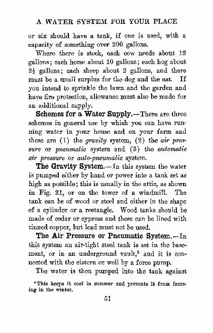
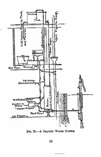
The Gravity System.—In this system the water
is pumped either by hand or power into a tank set as
high as possible; this is usually in the attic, as shown
in Fig. 21, or on the tower of a windmill. The
tank can be of wood or steel and either in the shape
of a cylinder or a rectangle. Wood tanks should be
made of cedar or cypress and these can be lined with
tinned copper, but lead must not be used.
The Air Pressure or Pneumatic System.—Inthis system an air-tight steel tank is set in the base-
ment, or in an underground vault,^ and it is con-
nected with the cistern or well by a force pump.
The water is then pumped into the tank against
"This keeps it cool in. summer and prevents it £rom freez-
ing in the winter.
51
S+ovc -
' Wa+«rFrfeofc
Fig. 21.—^A GBAvrrr Water System
52
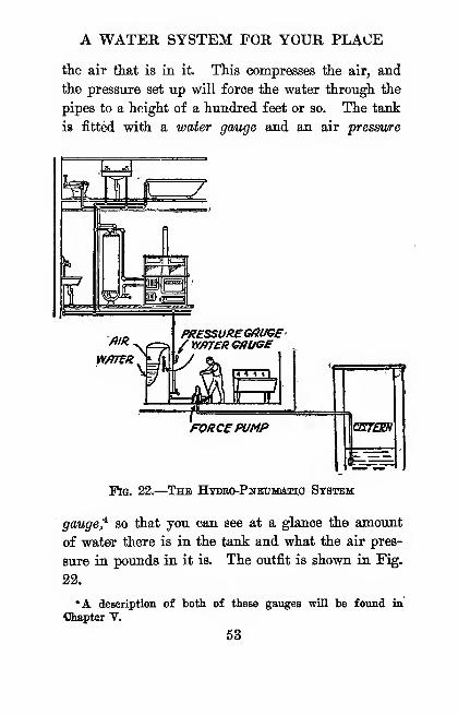
A WATER SYSTEM FOR YOUR PLACE
the air tliat is in it. This compresses the air, and
the pressure set up will force the water through the
pipes to a height of a hundred feet or so. The tank
is fitted with a water gauge and an air pressure
WfiTtR
PRESSUREGffOGe'/ WATER Gtiuee
Fig. 22.
—
The Hydeo-Pnedmiatio System
gauged so that you can see at a glance the amount
of water there is in the tank and what the air pres-
sure in pounds in it is. The outfit is shown in Fig.
22.
•A description of both of these gauges will be found in
Chapter V.
53

THE AMATEUR MECHANIC
The tank can be set up on end, that' is, upright,
or lengthwise, that is, in a horizontal position, ac-
cording to the room you have. The size of the tank
will, as before, depend, of course, on the amount of
water needed. A 220 gallon tank is about as large
as you can use to advantage with a hand pump, and
this will supply a family of five or six, provided all
of them do not take a bath every day. In figuring
the size of the tank, allow ^ of the space for the com-
pressed air.
As water absorbs the compressed air in the tank,
means must be provided to supply air to the tank.
This is done either by (1) an air inlet valve in the
suction pipe of the pump, (2) by using a combined
air and water pump or (3) by a separate air com-
pressor run by an engine or other motive power.
How to Figure the Capacity of a Tank.—To find the quantity of water a cylindrical tank will
"hold, figure it this way
:
C = Da X 0.7854 X d X 7.48
where C is the capacity in gallons of the tank you
want to find,
D2 is the diameter of the tank in feet squared,
0.7854 is a constant,
d is the depth of the tank in feetj and
7.48 is the number of gallons in a cubic foot.
To find the quantity of water a rectangular tank
will hold, use this formula
:
C = LXWXDX 7.48
54
A WATER SYSTEM FOR YOUR PLAGE
where C is the capacity in gallons of the tank
which you want to find,
L is the length of the tank,
W is the width of the tank,
D is the depth of the tank, and
7.48 is the niimher of gallons in a cubic foot.
The Weight of Water.—In putting up a tank,
due consideration must be given to its weight on the
structure supporting it, when it is full of water.
Knowing that the weight of a gallon of water is 8.4
pounds and tliat a cubic foot of water weighs 62.5
pounds, it is easy to find the total weight of water in
either a cylindrical or a rectangular tank.
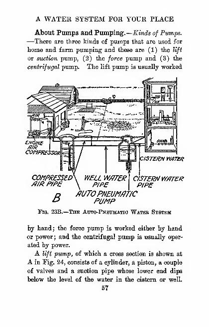
The Automatic Air, or Autd-pneumatic Sys-
tem.—As its name indicates, this system is worked
by compressed air which automatically delivers the
water direct from a lake or river, cistern or well, to
the faucets where it is to be used. The water, of
course, must be free from dirt.
The apparatus consists of (1) an engine or mo-
tive power of some kind, (2) an air compressor,
(3) a steel air tank and (4) an auto-pneumatic wa-
ter pump. The engine drives the compressor which
pumps the tank full of air to a pressure of from 40
to 100 pounds per square inch. The air tank is con-
nected directly with a pipe line to the pump, which
is placed near the bottom of the well or cistern.
Since the air in the air tank is under a high pres-
sure and the water pump works on a low pressure, a
55
THE AMATEUR MECHANIC
reducing valve is placed in the pipe line to lower the
pressure of the air and make it flow in a steady stream
to the pump.
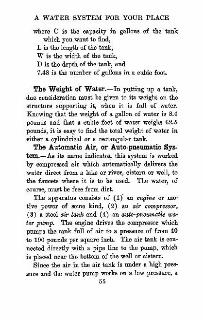
The pump is the chief part of the outfit and is
formed of two steel cylinders. These are connected
at the upper ends to the compressed air tank. In the
bottom of each cylinder is an ialet valve for the water
£XHJIV5t \fllR
iiV
VRV/UMECLDStCtEXHAUST
'AOfEOPEN,
tMpmtEPfilR
YmTEH
iNLET ^^
^ CYUNDERW CYUNDtk^, DISCHf)RGIN<5''JEXHAUSTIN0
WATER. ' AND REFILLING
Fig. 23A.—The Auto-Pnbumatio "Water Pump
to flow from the well or cistern, as in any force pimip.
Each cylinder is also fitted with an air exhaust valve
and, when the pump is submerged in the water, the
pipes from the exhaust valves project above the sur-
face of the water. Einally, each cylinder is con-
nected to the delivery pipe which carries the water to
the faucets. The operation of the system will be
readily understood from Fig. 23.
56
A WATER SYSTEM FOR YOUR PLACE
About Pumps and FvLvtrping.—Kinds of Pumps.
—There are three kinds of pumps that are used for
home and farm pumping and these are (1) the lift
or suction pump, (2) the force pump and (3) the
centrifugal pump. The lift pump is usually worked
ENGINE
COJ1PRESSE0/}/R P/PE
B
WELL W/?TERP/PE
fiUTOPNEUM/^T/CPUMP
CISTERN W/}T&i
aSTERNWPTERPIPE
Pig. 23B.
—
The Auto-Pneihiatio Water System
by hand; the force pump is worked either by hand
or power; and the centrifugal pump is usually oper-
ated by power.
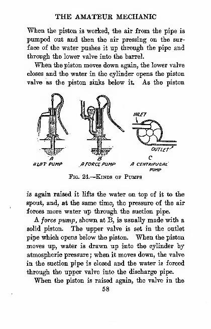
A lift pump, of which a cross section is shown at
A in Fig. 24, consists of a cylinder, a piston, a couple
of valves and a suction pipe whose lower end dips
below the level of the water in the cistern or well.
57
THE AMATEUR MECHANIC
When the piston is worked, the air from the pipe is
pumped out and iien the air pressing on the sur-
face of the water pushes it up through the pipe and
through the lower valve into the barrel.
When the piston moves down again, the lower valve
closes and the water in the cylinder opens the piston
valve as the piston sinks below it. As the piston
BaroKccPu/iP /> centrifugal
puhp
Fig. 24.
—
Kinds op Pumps
is again raised it lifts the water on top of it to the
spout, and, at the same time, the pressure of the air
forces more water up through the suction pipe.
A force pump, shown at B, is usually made with a
solid piston. The upper valve is set in the outlet
pipe which opens below the piston. When the piston
moves up, water is drawn up into the cylinder by
atmospheric pressure ; when it moves down, the valve
in the suction pipe is closed and the water is forced
through the upper valve into the discharge pipe.
When the piston is raised again, the valve in the
58
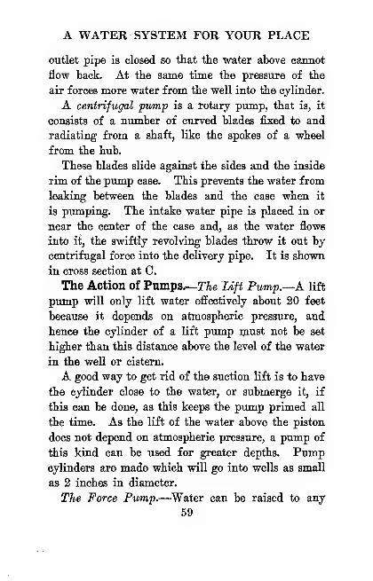
A WATER SYSTEM FOR YOUR PLACE
outlet pipe is closed so that the water above cannot
flow back. At the same time the pressure of the
air forces more water from the well into the cylinder.
A centrifugal pump is a rotary pump, that is, it
consists of a number of curved blades fixed to and
radiating from a shaft, like the spokes of a wheel
from the hub.
These blades slide against the sides and the inside
rim of the pump case. This prevents the water from
leaking between the blades and the case when it
is pumping. The intake water pipe is placed in or
near the center of the case and, as the water flows
into it, the swiftly revolving blades throw it out by
centrifugal force into the delivery pipe. It is shown
in cross section at 0.
The Action of Pumps.—T^e Lift Pump.—A lift
pump win only lift water effectively about 20 feet
because it depends on atmospheric pressure, and
hence the cylinder of a lift pump must not be set
higher than this distance above the level of the water
in the well or cistern.
A good way to get rid of the suction lift is to have
the cylinder close to the water, or submerge it, if
this can be done, as this keeps the pump primed all
the time. As the lift of the water above the piston
does not depend on atmospheric pressure, a pump of
this kind can be used for greater depths. Pumpcylinders are made which will go into wells as small
as 2 inches in diameter.
The Force Pump.—^Water can be raised to any
59
THE AMATEUR MECHANIC
Leight by means of a force pump. The purpose of
;the air chamber on a force pump is to make the water
flow in a continuous stream through the delivery pipe.
In this case, when the water is forced into the air
chamber, it covers the mouth of the delivery pipe
and, as it rises, it compresses the air that is in the
chamber. The pressure of it soon becomes great
enough to force the water through the delivery pipe
in a steady stream.
The Centrifugal Pump.—^As the blades of a cen-
trifugal pump do not fit air-tight, it is not positive
in its action, like a valve pump. It will not, there-
fore, exhaust the air from the suction line, so it must
be primed every time before it is started, no matter
how small the suction is.
To prime the pump, it must be at rest and both
the suction pipe and the pump case must be filled
with water. A small centrifugal pump will then
only lift water 10 or 15 feet, but it will deliver it
to a height of 35 feet or so. These pumps are largely
used for pumping water to boilers in steam heating
plants.
To Prevent Pipes from Freezing.—Where a
water pipe extends above the ground or is above the
frost level, it must be protected from freezing and
this can be done with a frost box.
To make this covering build three box tubes around
the pipe, as long as the part of it you want to pro-
tect, and cover the outside of each one with tar
paper. Have an air space of 6 inches all round be-
60

A WATER SYSTEM FOR YOUR PLACE
tween the inside and the pipe and an air space of 2
inches between each of the other two boxes. Keep
the boxes separated from each other by blocks or
trimmers, and you will have a good insulation against
the cold. Ordinary pipe coverings will not keep
water pipes that are out of doors from freezing.
To prevent underground water pipes from freez-
ing, the pipes must be buried to a depth of 3 or 4
feet.
When a Water Pipe Is Frozen.—^Where an ex-
posed pipe freezes, wrap woolen cloths around the
frozen part and pour hot water on it until it thaws.
If an underground pipe freezes, you will have to dig
down to it and thaw it out. If it is a large pipe,
you can do this by building a fire around it. If a
lead pipe bursts, it can be soldered, but if an iron
pipe bursts a new length of pipe will have to be put
in.
A Word on Plumbing and Sew&ge.—Plumb-ing.—^It is easy to do your own plumbing, for the days
of lead pipe with the trouble of making wiped joints
are over; instead iron pipe in all sizes and with all
the necessary fittings can be bought ready to put
together,^
Use 1 or IJ inch pipe for the main piping to the
supply tanks. The table on the next page shows the
sizes of pipes required for various branches.
Make all joints and fittings water-tight with red
• Write Sears, Eoebuck and Co. for their catalogue on Plumb-ing.
61

THE AMATEUR MECHANIC
TABLE
Branches from Main Pipe
OHAPTEE IV
A HEATING PLANT FOR YOUE HOME
There are many kinds of forces that perform
amazing feats, and one of the most active of these
is heat.
What Heat Is.—The most common way of pro-
ducing heat is by burning something, or comhustion,
as it is called. Combustion is caused by chemical
action.
As an illustration take oxygen and carbon^ These
two substances have a great attraction for each other,
and, if you can get a large quantity of oxygen and a
lot of carbon stored up separately, you have the means
for making a fire and hence of generating heat.
!Now air is formed of ^ part by volume of oxygen,
so you always have a supply of this gas at hand.
As coal is nearly pure carbon, you can get a supply,
of this (sometimes) if you have the money. Here,
then, are your separate stores of these combustible
chemicals, and all you need to do to start the chemical
action of combustion is to ignite them.
When combustion is going on, the particles, or
molecules, as they are called, of oxygen and carbon
combine and they vibrate at a rapid rate. These
63

THE AMATEUR MECHANIC
rapid to and fro motions impinging on our sense of
feeling set up the sensation that we call heat.
What Temperature Means.—Heat and temperw
z/z -
zoo190-
IBO
no160-
I50-
/to-
I30
IZOno-zoo
90-
80-
70-60-
5040-32-
ZO-
IO-\
BOILINGPOINT
'
F/iE£ZJNSPO/NT
'100'
-90
-80
70
-60
50
30
zo\
Ia
-0
-10
m. ,#F/fHRENHEIT CENTIGRffDE\
Fig. 25.
—
Fahrenheit and Centigrade Scales Cojipased
ture mean two entirely different things, though they
are very closely related.
Temperature is not only the degree to which a
64
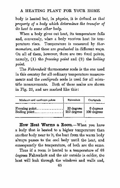
A HEATING PLANT FOR YOUR HOME
body is heated but, in physics, it is defined as that
property of a body which determines the transfer of
its heat to some other iody.
When a body gives out heat, its temperature falls
and, conversely, when a body receives heat its tem-
perature rises. Temperature is measured by ther-
mometers, and these are graduated in different ways.
On all of them, however, there are two fixed points,
namely, (1) the freezing point and (2) the boiling
point.
The FahrenJieU thermometer scale is the one used
in this country for all ordinary temperature measure-
ments and the centigrade scale is used for all scien-
tific measurements. Both of these scales are shown
in !Fig. 25, and are marked like this:
Minimum and maximum points

THE AMATEUR MECHANIC
xmless more lieat is constantly supplied to the room,
its temperature will fall.
How Heat Is Measured.— Since heat is a force,
it can be measured quite as exactly as wind, water,
steam or electricity.
Just as the unit of English lineal measure is the
inch and the unit of weight is the pound, so also the
tinit of heat is the British thermal unit, or B. T. U.,
as it is called for short, and this is the amount of
heat that is needed to raise the temperature of 1
pound of water 1 degree Fahrenheit.
About Heating and Ventilating.—On first
thought heating and ventilating may seem to have
little in common, yet a supply of pure, fresh air is
even more necessary than a supply of hot air. But
when you get both of them together you have the
ideal conditions that make for health and comfort.
Since this is true, in planning a house you should
provide for ventilating it at the same time that you
consider the best way of heating it, for the air sup-
ply should be heated before it is admitted to the
rooms.
Kinds of Heating Plants.—There are seven ways
a building can be heated, and named, these are (1)
by fireplaces, (2) by stoves, (3) by hot air furnaces
(4) by hot water systems, (5) by steam heating
plants, (6) by gas turners and (7) by electric heat-
ing apparatus.
The Cozy Fireplace.—Next to a fire in the center
of a wigwam with a hole in its top for the smoke
66
A HEATING PLANT FOR YOUR HOME
to get out, the fireplace is tlie oldest scheme of manto heat his ahode.
Fireplaces are used in present day homes chiefly
for the cheer and comfort they offer. They are very
wasteful of fuel, for 85 per cent of the stored up
energy of the wood or coal goes up the chimney;
but they are good ventilators, for the chimney makes
a draft and this pulls fresh air into the room.
To get the best results, fireplaces should he lined
with brick, and where grates are used they should
be set well above the level of the floor.
The Cheap Old Siove.—Since a stove is cheap,
portable and far more efficient than a fireplace, it has
all but supplanted the latter in the cheaper houses.
The bad features about a stove are that it dries the
moisture out of a room, it does not draw in any fresh
air, and it makes a lot of dirt. The best thing that
can be said of a stove is that it uses 50 per cent or
more of the heating energy of the fuel it burns.
The Hot Air Furnace.—To get rid of the trouble
and dirt of fireplaces and stoves, some genius got up
the scheme of hot air heating.
In this system a furnace is used which has a double
shell; the fire is built on a grate in the inside one,
or fire pot, and air is drawn in between it and the
outer shell or casing, where it is heated. The hot
air then passes through large pipes in the top of the
furnace, or dome, as shown in Fig. 26, where it flows
into the various rooms through iron openings, called
registers, set in the floors or baseboards. The regis-
67
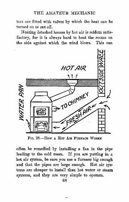
THE AIMATEUR MECHANIC
ters are fitted with valves by whicli the heat can be
turned on or cut off.
Heating detached houses by hot air is seldom satis-
factory, for it is always hard to heat the rooms on.
the side against which the wind blows. This can
HOT/J/R
W i
Fig. 26.—How a Hot Am Fubnace Works
often be remedied by installing a fan in the pipe
leading to the cold room. If you are putting in a
hot air system, be sure you use a furnace big enough
and that the pipes are large enough. Hot air sys-
tems are cheaper to install than hot water or steam
systems, and they are very simple to operate.
68
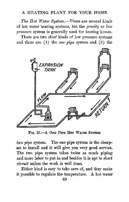
A HEATING PLANT FOR YOUR HOME
The Hot Water System.—There are several kim^s
of hot water heating systems, hut the gravity or low
pressure system is generally used for heating homes.
There are two chief kinds of low pressure systems
and these are (1) the one pipe system and (2) the
fh EXP/)NS/0//
Fig. 27.—A One Pipe Hot Water System
two pipe system. The one pipe system is the cheap-
est to install and it will give you very good service.
The two pipe system takes twice as much piping
and more labor to put in and besides it is apt to short
circuit unless the work is well done.
Either kind is easy to take care of, and they make
it possible to regulate the temperature. A hot water
69
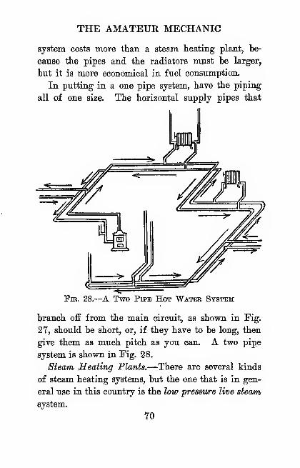
THE AMATEUR MECHANIC
system costs more than a steam heating plant, be-
cause the pipes and the radiators mjast be larger,
but it is more economical in fuel consumption.
In putting in a one pipe system, have the piping
all of one size. The horizontal supply pipes that
Two Pipe Hot WAMas System
branch off from the main circuit, as shown in Fig.
27, should be short, or, if they have to be long, then
give them as much pitch as you can. A two pipe
system is shown in Fig. 28.
Steam- Heating Plants.—There are several kinds
of steam heating systems, but the one that is in gen-
eral use in this country is the low pressure live stewm
system.
YO

A HEATING PLANT FOR YOUR HOME
A low pressure steam boiler is made just about
the same as a hot water boiler, but it is fitted
with a steam gauge, water gauge and safety valve
which operates the damper to regulate it.
/iUTOM/JT/C/^/R MV/fLVeFOR F^R/?D//?TOR ^ (^
Fig. 29.
—
A. One Pipe Steam Heating System
As in hot water heating, there are two schemes of
piping used, namely, (1) the one pipe system and
(2) the two pipe system. In the one pipe system,
and this is the one that is most widely used, a single
71
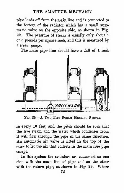
THE AMATEUR MECHANIC
pipe leads off from the main line and is connected to
the bottom of the radiator which has a small auto-
matic valve on the opposite side, as shown in Fig.
29. The pressure of steam is usually only about 4
or 5 pounds per square inch, and this is measured by
a steam gauge.
The main pipe line should have a fall of 1 inch
z m7Tf/ei///£
Fig. 30.—^A Two Pipe Steam Heating System
in every 10 feet, and the pitch should be such that
the live steam and the water which condenses from
it will flow through the pipe in the same direction.
An automatic air valve is fitted in the top of the
riser to let the air that collects in the main line pipe
escape.
In this system the radiators are connected on one
side with the main line of pipe and on the other
with the return pipe, as shovra in Fig. 29. Where72
A HEATING PLANT FOR YOUR HOME
this system is used the pipes can he of^ smaller
diameter than with the one pipe system. The lower
part of the pipe line of a steam heating plant should
always be even. Fig. 30 shows a two pipe line steam
heating system.
Noise in Steam Pipes.—The reason steam pipes
crack and pound is because the hot steam strikes on
the cold pipe or water caught in traps or pockets in
the pipe. When it is the latter, the cold water con-
denses the steam and this forms a vacuum which pulls
the water toward it with great force.
The chief thing you want to look after in installing
a steam heating plant is to give the pipes sufficient
pitch to carry off all the water formed in them and
not to have any uneven places or pockets to catch
the water.
To Find the Size of Heater Needed.—The size
of a hot air furnace, a hot water heater or a steam
boiler needed to heat a house can be found in several
ways.
The simplest method depends on the cubic con-
tents of the building to be heated and this is found
by multiplying the total exposure of the house by 50
and dividing it by 30,000 and the result will be the
number of square feet needed for the grate.
Gas Sealers.—Gas is used in nearly every city
for cooking ranges, but it is used only to heat houses
with as a makeshift, except in districts where there is
natural gas.
Electric Heating Apparatus.—Where water
73
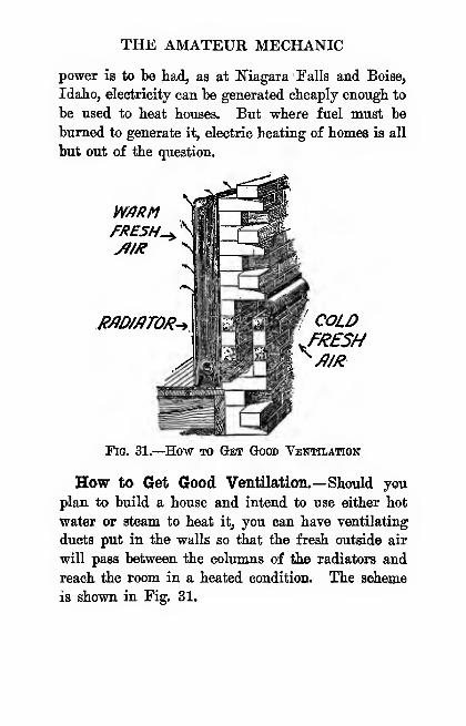
THE AMATEUR MECHANIC
power is to be had, as at Niagara Falls and Boise,
Idaho, electricity can he generated cheaply enough to
he used to heat houses. But where fuel must be
burned to generate it, electric heating of homes is all
but out of the question.
W/iRMFRESHES
R/JDMTOR- COLDJ'RESH^Jl/R
Fig. 31.—How to Get Good Ventilation
How to Get Good Ventilation.—Should you
plan to build a house and intend to use either hot
water or steam to heat it, you can have ventilating
ducts put in the walls so that the fresh outside air
will pass between the columns of the radiators and
reach the room in a heated condition. The scheme
is shown in Fig. 31.
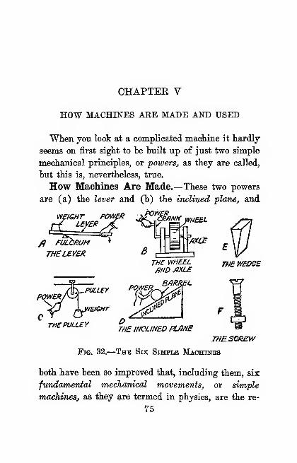
CHAPTEE V
HOW MACHINES ARE MADE AND USED
When you look at a complicated macliine it hardly
seems on first sight to be built up of just two simple
mechanical principles, or powers, as they are called,
but this is, nevertheless, true.
How Machines Are Made.—These two powers
are (a) the lever and (b) the inclined plane, and
weiGHT POWfKuy£R
^POWEH ^
fi FULC/iUM
THELEVER BTHE WHEELAND MLE
PULLEY
'EIGHT
POWER,
THE PULLEYTHE INCLINED PLME
THESCREW
Fig. 32.
—
The Six Simpi»e Machinks
both have been so improved that, including them, six
fimda/mental mechanical movements, or simple
muchinesj as they ^re termed in physics, are the re-
75
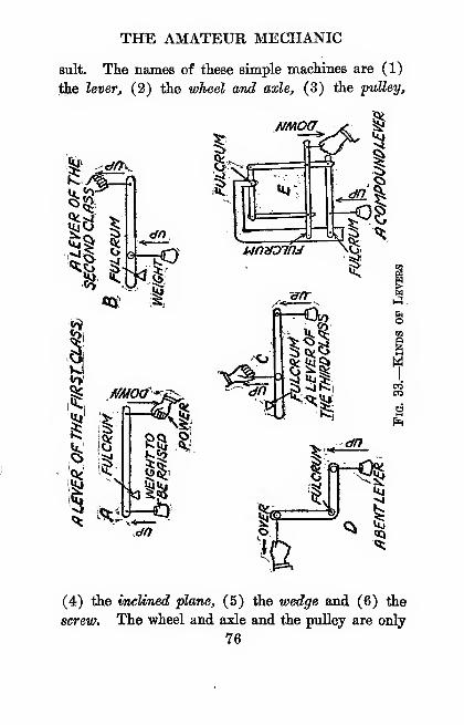
THE AMATEUR MECHANIC
suit. The names of these simple machines are (1)
the lever, (2) the wTireel and axle, (3) the pulley.
Iosi
<?5 ^4>.
cfn,
Q^^
f/Moa^i
I
(^dft
I
I"
NMOa^
Ui:
,^unnoiru
I
-^
dn
I?
1-3.
o
e«7
it
(4) the inclined "plana, (5) the wedge and (6) the
screw. The wheel and axle and the pulley are only
76
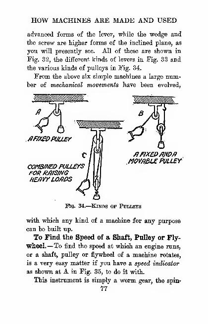
HOW MACHINES ARE MADE AND USED
advanced forms of the lever, while the wedge and
the screw are higher forms of the inclined plane, as
you will presently see. All of these are shown in
Fig. 32, the different kinds of levers in Fig. 33 and
the various kinds of pulleys in Fig. 34.
From the above six simple machines a large nxun-
ber of mechanical movements have been evolved,
.fiF/XeDPUU£r
coMB/u£i>puaersFORR/ltS/NGHE/IVYLO/fOS
^f/XEDfim/f/10Y/?fiL£ PULLEY
"Fig. 34.
—
^Kjnds of PtmLBTS
with which any kind of a machine for any purpose
can be built up.
To Find the Speed of a Shaft, Pulley or Fly-
wheel.—To find the speed at which an engine runs,
or a shaft, pulley or flywheel of a machine rotates,
is a very easy matter if you have a speed indicator
as shown at A in Fig. 35, to do it with.
This instrument is simply a worm gear, the spin-
77

THE AMATEUR MECHANIC
die of which has threads cut on it. These mesh with
the teeth of a gear to which an indicator dial is fixed.
To use the indicator, all you need to do is to set it at
0, note the time on your watch, and press the pointed
end of the spindle on the center of the end of the
fiSPEED INDICfiTOR r> WHEEL
SHAFT
RUBBER BEHEDWHEEL /JSURFACE SPEED
fiTTfiCHMENT
Fig. 35.
—
The Speed Indicator and How It Is Used
revolving shaft. In a minute read the dial, which
will give you the numher of revolutions per minute.
To find the surface speed, that is, the number of
lineal feet per minute the periphery, or surface, of
the wheel is traveling, a surface speed attachment is
used ; this consists of a rubber-banded wheel that can
be slipped over the spindle of the indicator, as shown
at B.
78
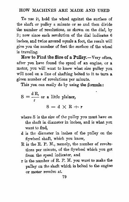
HOW MACHINES ARE MADE AND USED
To use it, hold the wheel against the surface of
the shaft or pulley a minute or so and then divide
the number of revolutions, as shown on the dial, by
2 ; now since each revolution of the dial indicates 6
inches, and twice around equals a foot, the result will
give you the number of feet the surface of the wheel
is traveling.
How to Find the Size of a Pulley.—Very often,
after you have found the speed of an engine, or a
motor, you will want to know what size pulley you
will need on a line of shafting belted to it to turn a
given number of revolutions per minute.
This you can easily do by using the formula :
S = —- or a little plainer,r
S = d X E -^ r
where S is the size of the pulley you must have on
the shaft in diameter in inches, and is what you
want to find,
d is the diameter in inches of the pulley on the
flywheel shaft, which you know,
E is the K. P. M., namely, the number of revohi-
tions per minute, of the flywheel which you get
from the speed indicator, and
r is the number of E. P. M. you want to make the
pulley on the shaft which is belted to the engine
or motor revolve at.
79
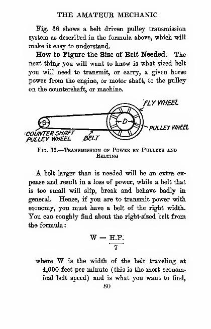
THE AMATEUR MECHANIC
Eig. 36 shows a belt driven pulley transmission
system as described in the formula above, which will
make it easy to understand.
How to Figure the Size of Belt Needed.—Thenext thing you will want to know is what sized belt
you will need to transmit, or carry, a given horse
power from the engine, or motor shaft, to the pulley
on the countershaft, or machine.
FLYWHEEL
\COUNTERSHAFTPULLEY WHEEL
PULLEY WHEEL
Fig. 36.
—
Transmission op Power by Pullets andBelting
A belt larger than is needed will be an extra ex-
pense and result in a loss of power, while a belt that
is too small will slip, break and behave badly in
general Hence, if you are to transmit power with
economy, you must have a belt of the right width.
You can roughly find about the right-sized belt from
the formula
:
W = H.P.
where W is the width of the belt traveling at
4,000 feet per minute (this is the most econom-
icalbelt speed) and is what you want to find,
80
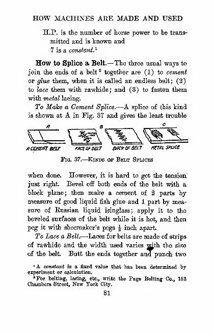
HOW MACHINES ARE MADE AND USED
H.P. is the number of horse ppwer to be trana-
mitted and is known and
7 is a constant.^
How to Splice a Belt.—The three usual ways to
join the ends of a belt^ together are (1) to cement
or glue them, when it is called an endless belt; (2)
to lace them with rawhide; and (3) to fasten them
with metal lacing.
To Make a Cement Splice.—A splice of this kind
is shown at A in Fig. 37 and gives the least trouble
fiCUJaTTBeW f/K£OfBaT BACK OFBELT MtTflL SPUC£
Fig. 37.
—
Kinds of Bki/t Splices
when done. However, it is hard to get the tension,
just right. Bevel off both ends of the belt with a
block plane; then make a cement of 2 parts bymeasure of good liquid fish glue and 1 part by mea-
sure of Kussian liquid isinglass; apply it to the
beveled surfaces of the belt while it is hot, and then
peg it with shoemaker's pegs | inch apart.
To Lace a Belt.—^Laces for belts are made of strips
of rawhide and the width used varies with the size
of the belt. Butt the ends together and punch two
'A oongtant is a fixed value that has been determined byexperiment or calculation.
'For belting, lacing, etc., write the Page Belting Co., 152Chambers Street, New York City.
81
THE AMATEUR MECHANIC
rows of holes in each end, as shown at B. Begin at
the center and lace it over to one edge, then back to
the other edge, and then to the center again. Lace
it so that the upper side of the lacing is parallel and
crosses over on the under side.
Metal Belt Lacing.—This is a steel punching, as
shown at C. To use it you only need to butt the
ends together, set it evenly over both ends, and drive
the sharp points through them. Turn the belt over,
clinch the points and drive them into the belt. It
is a quick and cheap way to make a joint.
A Good Belt Dressing.—A belt dressing is a
compound used to increase the friction and makes
'the wheel pull the belt without slipping,
(1) Take 37 per cent of boiled linseed oil and
mix it with 30 per cent of tallow; (2) mix 6 per
cent of beeswax with 27 per cent of machine oil, all
by measure. Heat 1 and 2 separately to 360 degrees
FahrenJieit and then mix together.
Gears and Toothed Wheels.—In mechanics the
word gear is used to mean two different things, name-
ly, (1) a gear is a gear wheel, or cogwheel, as it is
commonly called, that is, a wheel with teeth cut on its
rim, or periphery, which can mesh with another
toothed wKftfel or toothed rack, and (2) a gear is
made up of a whole set of parts of some mechanical
device, as the steering gear of an automobile. The
only kind of gears we will talk about here are gear,
wheels.

HOW MACHINES ARE MADE AND USED
There are five ordinary kinds of gears,' and
these are (1) spur gears, (2) internal gears,
(3) miter gears, (4) hevel gears and (5) crown
gears.
Spur Gears.—A spur gear is a gear with teeth
on its periphery. The three usual forms of this kind
of gear are (1) the spoked gear, (2) the webhed gear
PINION-
D RACK
fiRACKmo PINION
A-SPOKED B-WEBBED C-PLfllH
M /NTERN/ILGE/}/^
Tig. 38.
—
Kinds op Spur Gears
and (3) the plain gear, all of which are shown at
A, B and C in Fig. 38. A rack is a flat strip of
metal with teeth cut on one side of it, so that a spur
gear which has the same sized teeth will mesh with
it, as shown at D.
Internal Gears.—An internal gear is an inside, or
° For gears of all kinds, sprockets, etc., write the ChicagoModel Works, 166 West Madison Street, Chicago, 111., or
Luther H. Wightman and Co., Boston, Mass.
83
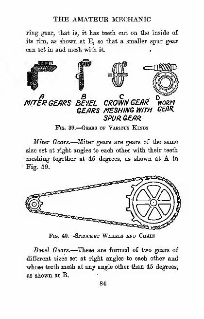
THE AMATEUR MECHANIC
ring gear, that is, it has teeth cut on the inside of
its rim, as shown at E, so that a smaller spur gear
can set in and mesh with it.
a R CMITER GEARS BEVEL CROWN GE/}R
GE/JRS /MESHING WTHSPUR G£./iR
Fig. 39.
—
Gears op Various Kinds
D ^WORMG£flR.
Miter Gears.—^Miter gears are gears of the same
size set at right angles to each other with their teeth
meshing together at 45 degrees, as shown at A in
Fig. 39.
Pig. 40.
—
Sprocket Wheels and Chain
Bevel Gears.—These are formed of two gears of
different sizes set at right angles to each other and
whose teeth mesh at any angle other than 45 degrees,
as shown at B.
84
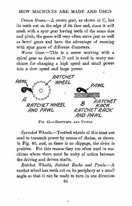
HOW MACHINES ARE MADE AND USED
Crown Gears.—A crown gear, as shown at C, has
its teeth cut on the edge of its face and, since it will
mesh with a spur gear having teeth of the same size
and pitch, the gears will very often serve just as well
as bevel gears and have the advantage of running
with spur gears of different diameters.
Worm Oear.—This is a screw working with a
spiral gear as shown at D and is used in many ma-
chines for changing a high speed and small power
into a slow speed and large power.
WHEELP/?WL
R/ITCHET WHEEL o j^^q^mo P/iWL R/ITCHETR/JCK
/)ND P/JWLFig. 41.—Eatchets and Pawls
8'prochei Wheels.—Toothed wheels of this kind are
used to transmit power by means of chains, as shown
in Fig. 40, and, as there is no slippage, the drive is
positive. For this reason they are often used in ma-
chines where there must be unity of action between
the driving and driven shafts.
Ratchet Wheels, Ratchet Racks and Pawls.—
A
ratchet wheel .has teeth cut on its periphery at a small
angle so that it can be made to turn in one direction
85
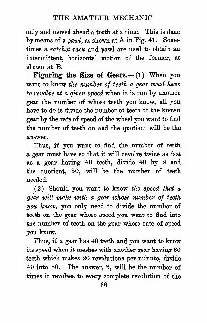
THE AMATEUR MECHANIC
only and moved ahead a tooth at a time. This is done
by means of a pawl, as shown at A in Fig. 41. Some-
times a ratchet rack and pawl are used to obtain an
intermittent, horizontal motion of the former, as
shown at B.
Figuring the Size of Crears.— (1) When you
want to know the number of teeth a gear must have
to revolve at a given speed when it is run by another
gear the number of whose teeth you know, aU you
have to do is divide the number of teeth of the known
gear by the rate of speed of the wheel you want to find
the number of teeth on and the quotient will be the
answer.
Thus, if you want to find the number of teeth
a gear must have so that it will revolve twice as fast
as a gear having 40 teeth, divide 40 by 2 and
the quotient, 20, vtIU be the number of teeth
needed.
(2) Should you want to know the speed that a
gear will make with a gear whose number of teeth
you know, you only need to divide the number of
teeth on the gear whose speed you want to find into
the number of teeth on the gear whose rate of speed
you know.
Thus, if a gear has 40 teeth and you want to know
its speed when it meshes vsdth another gear having 80
teeth which makes 20 revolutions per minute, divide
40 into 80. The answer, 2, will be the number of
times it revolves to every complete revolution of the
86
HOW MACHINES ARE MADE AND USED
gear -witli 80 teetli ; or 2 X 20, or 40, will be its num-
ber of revolutions per minutei.
Friction and What It Does.—There is no such
thing as a perfectly smooth surface. Even a sheet
of highly polished glass has minute elevations and
depressions on it, and, chiefly, because of these, if you
lay one sheet of glass on another and slip it along
it takes force to overcome the resistance, or friction,
as it is called.
l^ow, while friction is a useful thing in our daily
lives, since nails and screws would not hold and we
could not walk and an automobile could not run
without it, it is hard to contend with it in machin-
ery, for it takes a lot of power to overcome it and
this is wasted energy. The next best thing to
do is to reduce the friction as much as possible,
for this means to increase the efficiency of the ma-
chine.
How to Reduce Friction.—There are two kinds
of friction, and these are (1) sliding friction and
(2) rolling friction.
Where two surfaces slide on each other, one of
them should be harder than the other to reduce the
friction. Hence, steel shafts of machines are madeto revolve in bronze or babbitt bearings. The friction
between a rotating shaft and a fixed bearing is clearly
sliding friction. The following are a couple of anti-
friction alloys :*
'For bronze and babbitt write the Union Smelting and Be-fining Co., Avenue T) and 14th Street, New York City.
87
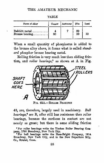
THE AMATEUR MECHANIC
TABLE
Name of Alloy
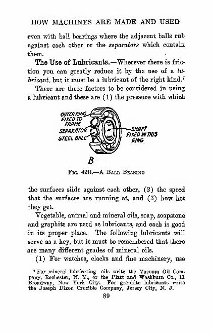
HOW MACHINES ARE MADE AND USED
even with ball bearings wbere the adjacent balls rub
against each other or the separators which contain
them.
The Use of Lubricants.—Wherever there is fric-
tion you can greatly reduce it by the use of a Ivr
hricant, but it must be a lubricant of the right kindJ
There are three factors to be considered in using
a lubricant and these are (1) the pressure with which
wnRRiNq.flX£D TO
ST£ELBML^WMJ %is
BFig. 42B.—A Ball Beaking
the surfaces slide against each other, (2) the speed
that the surfaces are running at, and (3) how hot
they get.
Vegetable, animal and mineral oils, soap, soapstone
and graphite are used as lubricants, and each is good
in its proper place. The following lubricants will
serve as a key, but it must be remembered that there
are many different grades of mineral oils.
(1) For watches, clocks and fine machinery, use
Tor mineral lubricating oils write the Vacuum Oil Com-pany, Eochester, N. Y., or the Piatt and Washburn Co., 11Broadway, New York City. For graphite lubricants write
the Joseph Dixon Crucible Company, Jersey City, N. J.
89
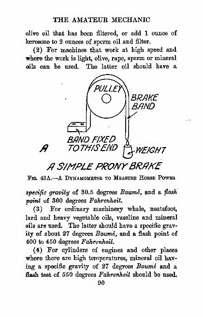
THE AMATEUR MECHANIC
oliTe oil that has been filtered, or add 1 ounce of
kerosene to 2 ounces of sperm oil and filter.
(2) For machines that work at high speed and
where the work is light, olive, rape, sperm or mineral
©ils can be used. The latter oil should have a
BRmcBrno
B/iND FIXEDTOTH/S5m hWEIGHT
/?S/MPLEPRONYBRmfFh3. 43A.—A Dtnamometeb to Measdbe HOrse Power
specific gravity of 30.5 degrees Baume, and a fiash
point of 360 degrees Fahrenheit.
(3) For ordinary machinery whale, neatsfoot,
lard and heavy vegetable oils, vaseline and mineral
oils are used. The latter should have a specific grav-
ity of about 27 degrees Baume, and a flash point of
400 to 450 degrees Fahrenheit.
(4) For cylinders of engines and other places
where there are high temperatures, mineral oil hav-
ing a specific gravity of 27 degrees Baume and a
flaah test of 550 degrees Fahrenheit should be used.
90
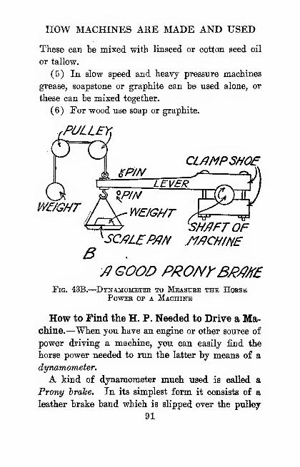
HOW MACHINES ARE MADE AND USED
These can be mixed with linseed or cotton seed oil
or tallow.
(5) In slow speed and heavy pressure machines
grease, soapstone or graphite can be used alone, or
these can be mixed together.
(6) For wood use soap or graphite.
PULLEY,
QCL/iMPSNOe
WE/GHT^ 'SH^FTOF
SC/?L£P/Jf^ /1/9CHINE
/^ GOOD PRONrBJ^maPig. 43B.
—
Dynamometer to Meastjee the HoesbPower of a Machine
How to Find the H. P. Needed to Drive a Ma-chine.—When you have an engine or other source of
power driving a machine, you can easily find the
horse power needed to run the latter by means of a
dynamometer.
A kind of dynamometer much used is called a
Promj hrahe. In its simplest form it consists of a
leather brake band which is slipped over the pulley
91

THE AMATEUR MECHANIC
of the macliine, as shown at A in Fig. 43. One end
is fixed to a support and a weight is hung on its free
end, which is just heavy enough to affect the speed
of the pulley which you can tell by your speed indi-
cator.
You can easily rig up a Prony brake and roughly
find the horse power needed to drive the machine
by the following formula:
„p ^ 3.1416 X D X R X W396,000
where H.P. is the horse power and is what you
want to find,
3.1416 is the diameter of the pulley in inches,
E is the number of revolutions of the pulley per
minute,
W is the weight of the weight on the end of the
brake band in pounds, and
396,000 is a constant.
Thus, if you put the brake band over a pulley
25 inches in diameter which is making 1056 revolu-
tions per minute, and you find that a weight of 10
pounds hung on the band just slows down its speed,
you can find the horse power by substituting the
figures for the formula above, thus
:
HP _ 3-1^16 X 25 X 1056 X 10 _' ' 396,000
'
which means that 2 H.P. are needed to turn the
pulley at that speed.
92
HOW MACHINES ARE MADE AND USED
A better thougli more complicated form of Prony
brake is shown at B, in "wbich a pair of brake shoes
are clamped around the shaft, and these absorb the
power which turns it. This is the really practical
type of dynamometer, but for your purposes the sim-
ple Prony brake will probably be accurate enough.

CHAPTER yi
PDTTING WIND A2n) WATER POWER TO WORK
The source of all the power we have that ia avail-
able for useful work is the sun and the two chief
natural powers due to it are (X) mnd power and (2)
water power.
Wind Powee
What Wind Power Is.—The unad, as we call it,
is simply a current of air and this is caused by the
sun heating some parts of it more than other parts.
To equalize this difference of temperature the cold
and heavy air flowing to the hot and lighter air sets
it in motion when it develops power in virtue of its
weight and speed.
Although the air is a yielding fluid, it acts just
about like a solid body if it is moving swiftly enough
or it is hit vsdth something hard enough. Thus,
when you fly a kite, the force of the vsdnd drives the
slanting kite up and out while you hold it in and
down. But, if the string should break and the kite
should keep the right slant, it would go on as long
as the wind lasted.
94

PUTTING WIND AND WATER TO WORK
The Parts of a Windmill.—There are seven chief
parts to a real windmill,^ of the kind that is used
in the United States, and these are (1) the tower,
(2) the turntable, (3) the main ^aft, (4) the wheel.
SH/IFT
'H^EL
TURN T/JBLt
TOWERTig. 44A.
—
The Parts of a Steel Windmill
(5) the gears, (6) the tailhone and (7) the van*, or
rudder, all of which are shown in Fig. 4-4-A-
The turntable is mounted on top of the tower and
connects the mill with it; the maiii shaft is fixed to
* For steel windmills, towers and pumps write to Woods andCo., 69 Park Place, New York City.
95
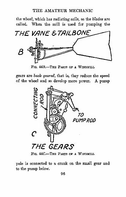
THE AMATEUR MECHANIC
the wlieel, which has radiating sails, as the blades are
called. When the mill is used for pumping the
THE V/^NE & Tfl/LBONE
B
Pig. 44B.
—
The Pabts of a Windmill
gears are hack geared, that is, they reduce the speed
of the wheel and so develop more power. A pump
TOpuhproo
THE GE/iRSFig. 44C.
—
The Paets of a Windmill
pole is connected to a crank on the small gear and
to the pump below.
96
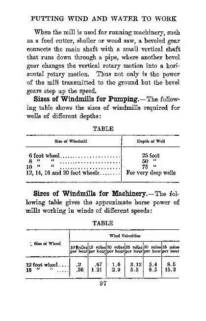
PUTTING WIND AND WATER TO WORK
When the mill is used for running machinery, such
as a feed cutter, sheller or wood saw, a beveled gear
connects the main shaft with a small vertical shaft
that runs down through a pipe, where another hevel
gear changes the vertical rotary motion into a hori-
zontal rotary motion. Thus not only is the power
of the mill transmitted to the ground hut the bevel
gears step up the speed.
Sizes of Windmills for Pumping.—The follow-
ing table shows the sizes of windmills required for
wells of different depths:
TABLE
Ssse of Windmill
THE AMATEUR MECHANIC
The Height of Efficient Winds.—If your wind-
mill is too low, the house, bam, trees, etc., will cut
off the force of the wind and this will reduce its
efficiency.
To get the best results, have the height of your
windmill 15 or more feet above all wind obstacles.
In any case, see to it that the tower is high enough
so that the lightest wind blowing from any direction
will have a clean sweep across the mill.
To Find the Height of Buildings, Trees, etc.—To know how high a tower you need to get the best
results, stand a pole 10 feet high in the sunshine
and measure the length of the shadow it casts. At
the same time measure the length of the shadow cast
by the highest building or tree nearest the place where
you are going to set up your windmill.
"Now divide the length of the shadow of the tree
or house by the length of the shadow of the pole, and
multiply the height of the pole by the quotient;
or, to make a formula of it so that it will be
H==^h
where H is the height of the house which you want
to find,
L is the length of the shadow of the tree or house,
1 is the length of the shadow of the pole, and
h is the height of the pole.
As an example, suppose that the shadow cast by the
98
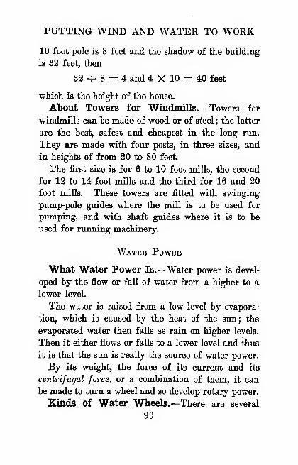
PUTTING WIND AND WATER TO WORK
10 foot pole is 8 feet and tlie shadow of the building
is 32 feet, then
32 -f- 8 = 4 and 4 X 10 = 40 feet
•which is the height of the house.
About Towers for Windmills.—Towers for
windmills can be made of wood or of steel ; the latter
are the best, safest and cheapest in the long run.
They are made with four posts, in three sizes, and
in heights of from 20 to 80 feet.
The first size is for 6 to 10 foot mills, the second
for 12 to 14 foot mills and the third for 16 and 20
foot mills. These towers are fitted with swinging
pump-pole guides where the mill is to be used for
pumping, and with shaft guides where it is to be
used for running machinery.
Watee Power
Wliat Water Power Is.—Water power is devel-
oped by the flow or fall of water from a higher to a
lower leveL
The water is raised from a low level by evapora-
tion, which is caused by the heat of the sun; the
evaporated water then falls as rain on higher levels.
Then it either flows or falls to a lower level and thus
it is that the sun is really the source of water power.
By its weight, the force of its current and its
centrifugal force, or a combination of them, it can
be made to turn a wheel and so develop rotary power.
Kinds of Water Wheels.—There are several
99
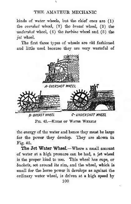
THE AMATEUR MECHANIC
kinds of water wheels, but the chief ones are (1)
the overshot wheel, (2) the breast wheel, (3) the
undershot wheel, (4) the turbine wheel and (5) the
jet wheel.
The first three types of wheels are old fashioned
and little used because they are very wasteful of
B-BREfiST WHEEL C- UNDERSHOT WHEEL
Fig. 45.
—
Kinds of Water Wheels
the energy of the water and hence they must be large
for the power they develop. They are shown in
Fig. 45.
The Jet Water Wheel.—Where a small amount
of water at a high pressure can be had, a jet wheel
is the proper kind to use. This wheel has eups, or
buckets, set around its rim, and the wheel, which is
small for the horse power it develops as against the
ordinary water wheel, is driven at a high speed by
100
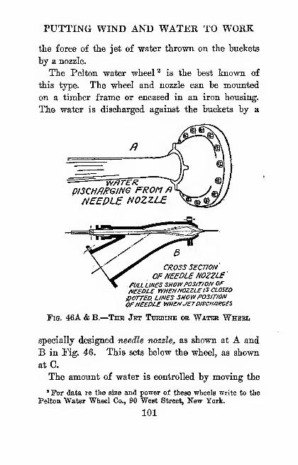
PUTTING WIND AND WATER TO WORK
the force of tlie jet of water thrown on the buckets
by a nozzle.
The Pelton water wheel ^ is the best known of
this type. The wheel and nozzle can be mounted
on a timber frame or encased in an iron housing.
The water is discharged against the buckets by a
01SCH/URGING FROM fl ^
NEEDLE NOZZLE
CROSS SECTION
OF NEEDLE NOZZLE
'
. FULL LINES SHOWPOSJTION OFNEEDLE WHENNOZZLEIS CLOSED
POTTED. LINES SHOWPOSITIONOFNEEDLE WHENJETD/SCH/}RB£S
Pig. 46A & B.
—
The Jet Tuebine ob Water Wheel
specially designed needle nozzle, as shown at A and
B in Fig. 46. This sets below the wheel, as shown
at C.
The amount of water is controlled by moving the
' For data re the size and power of these wheels write to the
Pelton Water Wheel Co., 90 West Street, New Tork.
101
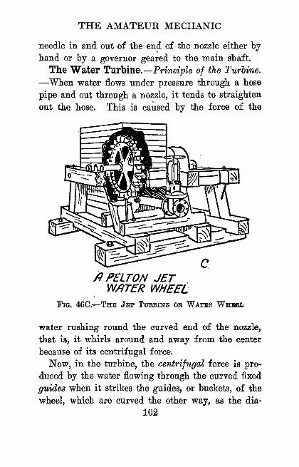
THE AMATEUR MECPIANIC
needle in and out of the end of the nozzle either by
hand or by a governor geared to the main shaft.
The Water TvLrhme.—Principle of the Turbine.
—^When water flows under pressure through a hose
pipe and out through a nozzle, it tends to straighten
out the hose. This is caused by the force of the
fl PELTON JETW/ITER WHEEL
Fig. 46C.
—
The Jet Turbine or Water Whsel
water rushing round the curved end of the nozzle,
that is, it whirls around and away from the center
because of its centrifugal force.
Now, in the turbine, the centrifugal force is pro-
duced by the water flowing through the curved fixed
guides when it strikes the guides, or buckets, of the
wheel, which are curved the other way, as the dia-
102
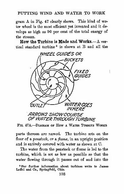
PUTTING WIND AND WATER TO WORK
gram A in Fig. 47 clearly shows. This kind of wa-
ter wheel is the most efficient yet invented and it de-
velops as high as 90 per cent of the total energy of
the stream.
How the Turbine is Made and Works.—A ver-
tical standard turbine® is shown at B and all the
yyHEEL GU/P£S OR-BUCKETS
GU/DES
VUnlf W/PTEPGOfS//V//E/?E
JJRPOWS SNOWCOUR5EOFW/PrER THRCXJGH TURB/NE
Fig. 47A.
—
Diagram op How a Water Turbine Works
parts thereon are named. The turbine sets on the
floor of a penstock, or a flv/me, in an upright position
and is entirely covered with water as shown at 0.
The water from the penstock or flume is led to the
turbine, which is set as low as possible so that the
water flowing through it passes out of and into the
'For further information about turbines write to JamesLefEel and Co., Springfield, Ohio.
103
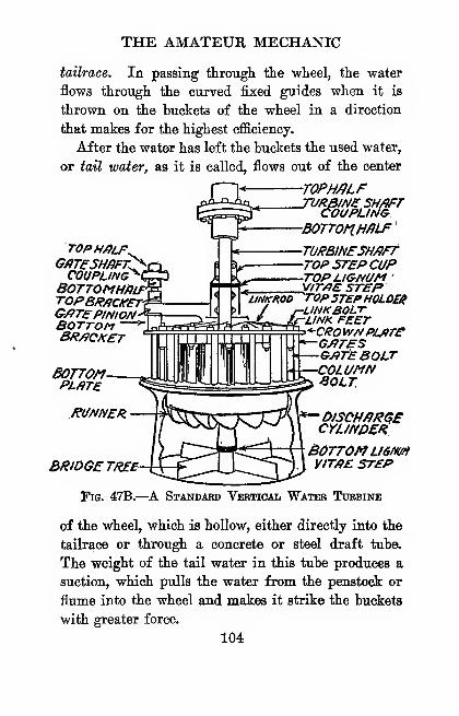
THE AMATEUR MECHANIC
tailrace. In passing through the wheel, the water
flows through the curved fixed guides when it is
thrown on the buckets of the wheel in a direction
that makes for the highest efficiency.
After the water has left the buckets the used water,
or taU water, as it is called, flows out of the center
TOPH/}LFTVRBlNe 5H/)Fr
COUPLINGBOTTOnn^LF'
TURBINESH/)rrTOP STEP CUPTOPLI&NUM '
TOPHALFGPTESHfiFT^\COUPLING^f
BOTTOMHtiiroPBPflCICET\G/fTePlNIONBOTTOM ~
BRACKET
BOTTOMPLATE
{RUNNER
BRIOGETREE
^ yijr/iE STEP^JNKWOTOPSTEPHOLDER
r-UNKBOlX«U...A-/W/f FEET^ ri r n ,-'rCI?0WNPL/ITE
G/fTES&/?TEBQLrCOLUMNBOLT
^DlSCHffRGECYUNDER
Bottom usrwfiVIT/}E STEP
Fig. 47B.—^A Standard Vertical Watbb Turbine
of the wheel, which is hollow, either directly into the
tailrace or through a concrete or steel draft tube.
The weight of the tail water in this tube produces a
suction, which pulls the water from the penstock or
flume into the wheel and makes it strike the buckets
with greater force.
104
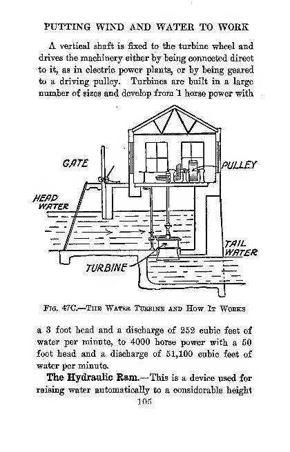
PUTTING WIND AND WATER TO WORK
A vertical shaft is fixed to the turbine wheel and
drives the machinery either by being connected direct
to it, as in electric power plants, or by being geared
to a driving pulley. Turbines are built in a large
number of sizes and develop from 1 horse power with
PULLEY
HEAPW/ITER
TAILWflTEH
Fig. 47C.
—
The "Water Tuebine and How It Woeks
a 3 foot head and a discharge of 252 cubic feet of
water per minute, to 4000 horse power with a 50
foot head and a discharge of 51,100 cubic feet of
water per minute.
The Hydraulic Ram.—This is a device used for
raising water automatically to a considerable height
lOR
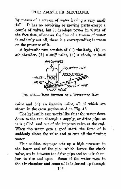
THE AMATEUR MECHANIC
by means of a stream of water having a very smalj
fall. It has no revolving or moving parts except a
couple of valves, but it develops power in virtue of
the fact that, whenever the flow of a stream of water
is suddenly cut off, there is a corresponding increase
on the pressure of it.
A hydraulic ram consists of (1) the body, (2) an
air chamber, (3) a sniff valve, (4) a check, or irdet
^filRCHmSEBi
PEUY£RY PIPS
^^^;:^^UPPLY PIPE'SNIFF HOLE
Fis. 48A.
—
Cross Section op a Hydraulic Ram
uoZue and (5) an impetus valve, all of which are
shown in the cross section at A in Fig. 48.
The hydraulic ram works like this : the water flows
down to the ram through a supply, or drive pipe, as
it is called, and out of the impetus valve at the end.
When the water gets a good start, the force of it
suddenly closes the valve and so cuts off the flowing
water.
This sudden stoppage sets up a high pressure in
the lower end of the pipe which forces the check
valve, set in between the drive pipe and the air cham-
ber, to rise and open. Some of the water rises in
the air chamber and some of it is forced up through
106
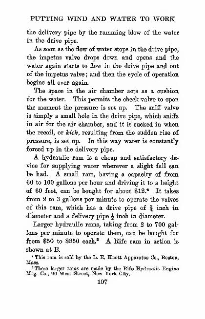
PUTTING WIND AND WATER TO WORK
the delivery pipe by the ramming blow of the water
in the drive pipe.
As soon as the flow of water stops in the drive pipe,
the impetus valve drops down and opens and the
water again starts to flow in the drive pipe an(i out
of the impetus valve ; and then the cycle of operation
begins all over again.
The space in the air chamber acts as a cushion
for the water. This permits the check valve to open
the moment the pressure is set up. The sniff valve
is simply a small hole in the drive pipe, which sniffs
in air for the air chamber, and it is sucked in whenthe recoil, or hich, resulting from the sudden rise of
pressure, is set up. In this way water is constantly
forced up in the delivery pipe.
A hydraulic ram is a cheap and satisfactory de-
vice for supplying water wherever a slight fall can
be had. A small ram, having a capacity of from
60 to 100 gallons per hour and driving it to a height
of 60 feet, can be bought for about $12.* It takes
from 2 to 3 gallons per minute to operate the valves
of this ram, which has a drive pipe of f inch in
diameter and a delivery pipe ^ inch in diameter.
Larger hydraulic rams, taking from 2 to 700 gal-
lons per minute to operate them, can be bought for
from $50 to $850 each." A Eife ram in action is
shown at B.* This ram is sold by the L. E. Knott Apparatus Co., Boston,
Mass.
'These larger rams are made by the Eife Hydraulic EngineMfg. Co., 90 West Street, New York City.
107

THE AMATEUR MECHANIC
What "Head of Water" Means.—Before you
install a water wlieel, turbine or ram, you should first
find (1) the head of water in feet that you are going
to use, (2) the quantity of water in cubic feet that
flows per minute, and from these two factors a simple
calculation will give you (3) the horse power of the
JNTflKErmn
SUPPLY^PIP£
Fig. 48B.
—
The Hydraulic Eam at Woek
water supply, and then you will know what size water
wheel or turbine you should use.
By head of water is meant the distance the water
actually falls to operate the wheel or ram. Now,
there are two kinds of heads of water, and these are
(1) the static, or surveyed head, and (2) the net,
running or effective head.
The static, or surveyed head as it is called, is sim-
108
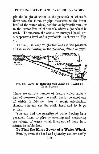
PUTTING WIND AND WATER TO WORK
ply the height of water in the penstock or where it
flows into the flume or pipe measured to the lower
level of the water wheel, turbine or hydraulic ram, or
to the center line of the nozzle where a jet wheel is
used. To measure the static, or surveyed head, use
a carpenter's level and a yardstick, as shown in Fig.
49.
The net, running or effective head is the pressure
of the water flowing in the penstock, flume or pipe.
_a__»^_ ^-< ,f\..Sf'?ZQU:fY?tCi .
^^^3^1^^^™nK^ I
MWB? ^^*^^^»fa|r^ \yJKDSTICK /v9it
Fig. 49.—How to Measure the Head op Water opYoTJR Supply
There are quite a number of factors which cause a
loss of pressure from the static head, the chief one
of which is friction. For a rough calculation,
though, you can use the static head and let it go
at that.
You can find the quantity of water flowing in a
penstock, flume or pipe by catching and measuring
the voliune of water which flows out of them in 1
minute in cubic feet.
To Find the Horse Power of a Water Wheel.
—Finally, from the head and quantity you can easily
109

ri'HE AMATEUR MECHANIC
calculate the gross horse power of the water wheel by
means of this formula
:
G.H.P. = .00189 X H X Qwhere G.H.P. ia the gross horse power and is
what you want to find,
.00189 is a constant,
H is the head in feet and which you have measured,
and Q is the quantity of water in cubic feet per
minute and is known.
Thus, if you have a head of 30 feet and a pipe
delivering 2,700 cubic feet of water per minute,
the gross horse power will be
G.H.P. => .00189 X 30 X 2,700 = 153.29
Actual Horse Power of the Water Wheel.—As a matter of fact, a water wheel is only about 80
per cent efficient and to find the actual horse power
of the water wheel, you will have to multiply the
gross horse power by .80. Then, in the preceding
example, the actual horse power of the water wheel is
153.29 X .80, or only 122.68.
To Find the Amount of Water Delivered by a
Ram.—^You can find the amount of water delivered
by a hydraulic ram from the following formula:
H X Q X 40G^- 5
where G is the number of gallons delivered and is
what you want to know,
110
PUTTING WIND AND WATER TO WORK
H is the Lead in feet and which you know,
Q is the quantity of water in gallons (not cubic
feet) per minute and which you know,
40 is a constant, and
D is the height you want the water delivered to.
Thus, if you have a head of 30 feet and a pipe
delivering 2,700 gallons per minute and you want
the ram to deliver this amount of water at a height
of 84 feet, the amount of water delivered per hour
will be
30 X VOO X 40 840,000G = ==
—
'- = 10,000 gallons84 84
per hour.

CHAPTEK YII
MAKING THE STEAM ENGINE WORK FOE YOU
Steam is the great prime power and it has done
more to aid and ahet civilization than all the other
powers put together. To generate steam a boiler
must be used, and to make the steam develop power
an engine is necessary.
Ifow while a steam boiler and engine, or power
plant as it is called, costs more to buy and to run
than a windmill or a water wheel, a gas, gasoline
or an oil engine, it is a far more certain source of
power than any of these and it runs more smoothly
and starts off with the full load the instant the steam
is turned on.
About the Energy of Steam.—^When 1 cubic
inch of water is heated and changed into steam the
latter will expand until it takes up nearly 1 cubic
foot of space.
When water is heated to 2'12 degrees Fahrenheit
it boils, and the more heat you apply to the water
the more steam you will get and the hotter it will be.
Steam which can be seen is not real steam at all,
but merely little drops of water that have been con-
densed by the cold air and carried up by the real
steam, which is much hotter and quite invisible.
112

MAKING THE STEAM ENGINE WORK
Now the heat of steam is of two kinds and these
are (1) kinetic heat, that is, heat which makes the
steam move, and this is what we call sensible heat,
and (2) potential heat, that is, heat that is stored
up in the steam, or latent heat, as it is called.
One of the curious things about energy of any kind
is that it can be changed from energy of motion to
energy at rest, and the other way about, with won-
derful facility and quickness. Hence sensible heat
can be changed into latent heat and vice versa. In
an engine it does this in such a way that all the power
there is in the steam is gotten out of it.
What Steam Pressure Is.—When water is
heated to make steam the particles of water, or
molecules, as they are called, are torn off from it
and thess are forced out in straight lines like minia-
ture cannon balls. They keep on going until they
hit other molecules or strike the sides of the vessel
containing them.
This continual pounding away of the molecules of
steain inside the boiler or the cylinder of an engine
is so swift and hard that it sets up streams of force
in every direction and this force and the extent of
it is what is meant by the term steam pressure.
How Steam is Measured.—In this country steam
pressure is measured in pounds, and this is done by
connecting a steam, gauge to the boiler near the top
where the steam is hottest. The pressure of the
steam acts on a mechanism that makes a needle swing
over a dial, which is graduated to read in pounds.
113
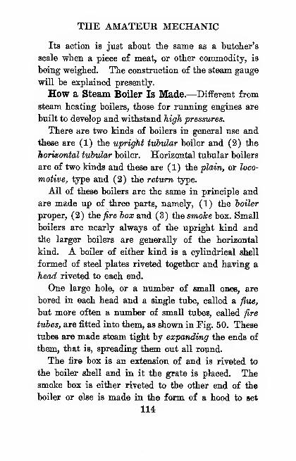
THE AMATEUR MECHANIC
Its action is just atout tlie same as a butcher's
scale wlieii a piece of meat, or other commodity, is
being weighed. The construction of the steam gauge
will be explained presently.
How a Steam Boiler Is Made.—Different from
steam heating boilers, those for running engines are
built to develop and withstand high pressures.
There are two kinds of boilers in general use and
these are (1) the upright iubular boiler and (2) the
horizontal tubular boiler. Horizontal tubular boilers
are of two kinds and these are (1) the plain, or loco-
motive, type and (2) the return type.
All of these boilers are the same in principle and
are made up of three parts, namely, (1) the toiler
proper, (2) the fire box and (3) the smoJce box. Small
boilers are nearly always of the upright kind and
the larger boilers are generally of the horizontal
kind. A boiler of either kind is a cylindrical shell
formed of steel plates riveted together and haviag a
head riveted to each end.
One large hole, or a number of small ones, are
bored in each head and a single tube, called a flue,
but more often a number of small tubes, called fire
tubes, are fitted into them, as shown in Fig. 50. These
tubes are made steam tight by expanding the ends of
them, that is, spreading them out all round.
The fire box is an extension of and is riveted to
the boiler shell and in it the grate is placed. Thesmoke box is either riveted to the other end of the
boiler or else is made in the form of a hood to set
114
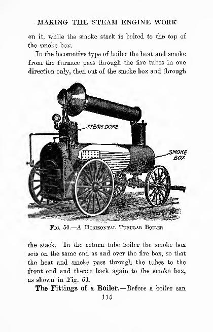
MAKING THE STEAM ENGINE WORK
on it, while the smoke stack is bolted to the top of
the smoke box.
In the locomotive type of boiler the heat and smoke
from the fiirnace pass through the iire tubes in one
direction only, then out of the smoke box and through
Fig. 50.—A Horizontal Tubular Boiler
the stack. In the return tube boiler the smoke box
sets on the same end as and over the fire box, so that
the heat and smoke pass through the tubes to the
front end and thence back again to the smoke box,
as shown in Fig. 51.
The Fittings of a Boiler.—Before a boiler can
115

THE AMATEUR MECHANIC
be used to get up steam it must have a mimLcr of
fittings. Chief among these are (1) the water in-
take pipe. (2) the ivater pump, (3) the water gauge,
(4) the steayn delivery pipe, (5) the steam gauge
cocTcs, (6) the steam, gauge, (7) the safety valve and
(8) the steam whistle.
SMOKE STLRtI OE.UY£JiY F//?£ FE/7/iSMOKe
STfiCK .PIPE TUBES BOX
FRONT'^- SMOKE''
BOX.
Fig. 51.
—
The Return Tubular Boiler
(1) The water intake pipe connects the lower part
of the boiler below the water line with a source of
water. An ordinary globe valve is fitted to the in-
take pipe near the boiler and (2) a force pump is
coupled to this and to the water supply to feed the
water into the boiler against its hack pressure.
(3) The water gauge is fitted to the shell of the
boiler at the water line. It is formed of a long,
upright glass tube set in two wheel valves, both of
which connect with the boiler, as shown at A in Fig.
52. Since water seeks its own level, whatever the
size, shape or position of the connecting vessel may116
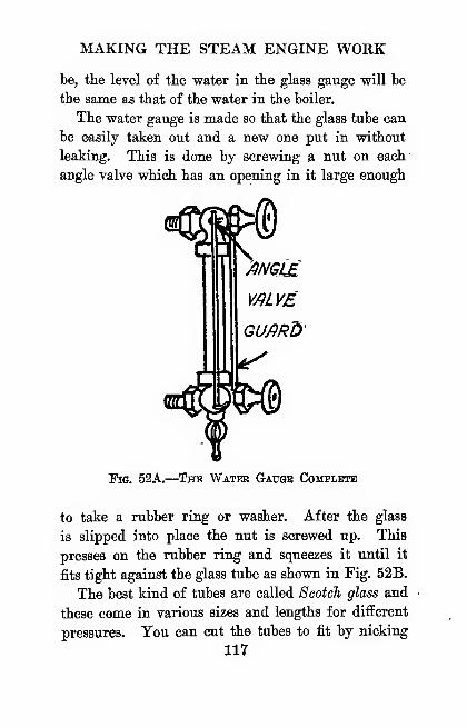
MAKING THE STEAM ENGINE WORK
be, the level of the water in the glass gauge will be
the same as that of the water in the boiler.
The water gauge is made so that the glass tube can
be easily taken out and a new one put in without
leaking. This is done by screwing a nut on each'
angle valve which has an opening in it large enough
Fig. 52A.
—
^The Water Gauge Cohplete
to take a rubber ring or washer. After the glass
is slipped into place the nut is screwed up. This
presses on the rubber ring and squeezes it until it
fits tight against the glass tube as shown in Fig. 52B.
The best kind of tubes are called Scotch glass and
these come in various sizes and lengths for different
pressures. You can cut the tubes to fit by nicking
117

THE AMATEUR MECHANIC
tbem with a file, or, better, use a regular water gauge
glass cutter.^
(4) The steam delivery pipe is screwed in the top
of the boiler, if it is an upright one, or in the steam
dome, if it is of the horizontal type, so that the hot-
THI5ENDSCREWSINTO BOILER
RUBBERW/?SHER-
NUT
GLms TUBE
TH/SENDSCREWS/NTO BOILER
Fig. 52B.
—
Cross Sections of a Water Gauge
test steam, which has the most energy in it, will be
delivered to the engine. A globe valve is fitted to
this pipe near the boiler so that the steam can be
cut off at this point if needs ba
(5) Three gauge cocks are fitted into the shell of
' These can be bought of Hammaoher, Schlemmer and Co.,
Fourth Avenue and 13th Street, New York City.
118
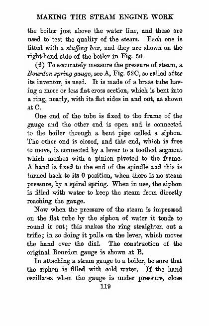
MAKING THE STEAM ENGINE WORK
tte boiler just above the water line, and tbese are
used to test the quality of the steam. Each one is
fitted with a stuffing box, and they are shown on the
right-hand side of the boiler in Fig. 50.
(6) To accurately measure the pressure of steam, a
Bourdon spring gauge, see A, Fig. 520, so called after
its inventor, is used. It is made of a brass tube hav-
ing a more or less flat cross section, which is bent into
a ring, nearly, with its flat sides in and out, as shown
atC.
One end of the tube is fixed to the frame of the
gauge and the other end is open and is connected
to the boiler through a bent pipe called a siphon.
The other end is closed, and this end, which is free
to move, is connected by a lever to a toothed segment
which meshes with a pinion pivoted to the frame.
A hand is fixed to the end of the spindle and this is
turned back to its position, when there is no steam
pressure, by a spiral spring. When in use, the siphon
is filled with water to keep the steam from directly
reaching the gauge.
Now when the pressure of the steam is impressed
on the flat tube by the siphon of water it tends to
round it out; this makes the ring straighten out a
trifle ; in so doing it pulls on lie lever, which moves
the hand over the dial. The construction of the
original Bourdon gauge is shown at B.
In attaching a steam gauge to a boiler, be sure that
the siphon is filled with cold water. If the hand
oscillates when the gauge is under pressure, close
119

THE AMATEUR MECHANIC
StPHON '^TOBOILEIi
NEEDLE
E/XEP ENi BRfiSSTUBE
f FREE ENDTHISEND SCREWS nPTURP/N BOILER ^^ ^^^^
Fig. 52C.—^A Steam Peessure Gauge
the cock a little, but not enough to reduce the pres-
sure on the gauge. Always buy a gauge that is
graduated to double the working pressure of the
boiler, as this will insure accuracy. Fig. 520.
120

MAKING THE STEAM ENGINE WORK
(7) Every boiler must have a safety valve, so that
the steam will blow off automatically before the pres-
sure becomes dangerous. The safety valve for
stationary engines is usually of the weight and lever
type, as shown in Eig. 52D.
It consists of a valve in which a conical plug fits
into a similarly shaped opening ; this plug is held in
its seat by a lever pivoted to the boiler at one end
j/y/////^////
Fig. 52D.—How a Safety Valve Works
and carrying a sliding weight on its free end. To
make the valve blow off when a given pressure is
reached, aU you have to do is slide the weight along
the graduated lever to the notch marked with the
number of pounds you want.
A bell whistle is the kind that is blown by steam
and is so called because the steam striking a cylin-
drical, open-mouthed tube makes it vibrate like a bell.
The whistle is formed of a heavy piece of tube
closed at one end for the bell. This is fixed to a
cup by means of a standard, and the cup in turn is
fastened to the stem of a stopcock. Holes are drilled
121
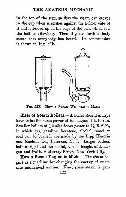
THE AMATEUR MECHANIC
in the top of the stem so that the steam can escape
in the cup when it strikes against the hollow side of
it and is forced up on the edge of the hel|, which sets
the hell to vibrating. Then it gives forth a lusty
sound that everybody has heard. Its construction
is shown in Fig. 52E.
j^=iT
Fig. 52E.—How a Steam Whistle is Made
Sizes of Steam Boilers.—A boiler should always
have twice the horse power of the engine it is to run.
Smaller boilers of ^ boUer horse power to IJ B.H.P.,
in which gas, gasoline, kerosene, alcohol, wood or
coal can be burned, are made by the Lipp Electric
and Machine Co., Paterson, N. J. Larger boilers,
both upright and horizontal, can be bought of Done-
gan and Swift, 6 Murray Street, New York City.
How a Steam Engine is Made.—The steam en-
gine is a machine for changing the energy of steam
into mechanical motion. Now, since steam is gen-
122
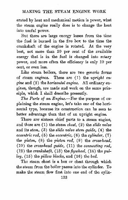
MAKING THE STEAM ENGINE WORK
erated by heat and mechanical motion is power, what
the steam engine really does is to change the heat
into useful power.
But there are large energy losses from the time
the fuel is burned in the fire box to the time the
crankshaft of the engine is rotated. At the very
best, not more than 20 per cent of the available
energy that is in the fuel is changed into rotary
power, and more often the efficiency is only 10 per
cent, or even less.
Like steam boilers, there are two generic forms
of steam engines. These are (1) the upright en-
gine and (2) the horizontal engine. All ordinary en-
gines, though, are made and work on the same prin-
ciple, which I shall describe presently.
The Parts of an Engine.—For the purpose of ex-
plaining the steam engine, let's take one of the hori-
zontal type, because its construction can be seen to
better advantage than that of an upright engine.
There are sixteen chief parts to a steam engine,
and these are (1) the steam chest, (2) the slide valve
and its stem, (3) the slide valve stem guide, (4) the
eccentric rod, (5) the eccentric, (6) the cylinder, (7)
the piston, (8) the piston rod, (9) the cross-head,
(10) the cross-head guide, (11) the connecting rod,
(12) ih.e crankshaft, (13) Hie flywheel, (14) tiie pul-
ley, (15) the pillow blocks, and (16) the bed.
The steam chest is a box or chest through which
the steam from the boiler passes into the cylinder. Tomake the steam flow first into one end of the cylin-
123
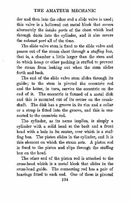
THE AMATEUR MECHANIC
der and then into the other end a slide valve is used
;
this valve is a hollowed out metal block that covers
alternately the intake ports of the chest which lead
through ducts into the cylinder, and it also covers
the exhaust port all of the time.
The slide valve stem is fixed to the slide valve and
passes out of the steam chest through a stuffing hox,
that is, a chamber a little larger than the stem and
in which hemp or other packing is stuffed to prevent
the steam from leaking out when the stem slides
forth and back.
The end of the slide valve stem slides through its
guide; to the stem is pivoted the eccentric rod
and the latter, in turn, carries the eccentric on the
end of it. The eccentric is formed of a metal disk
and this is mounted out of its center on the crank-
shaft. The disk has a groove in its rim and a collar
or a strap is fitted into the groove, and this is con-
nected to the eccentric rod.
The cylinder, as its name implies, is simply a
cylinder with a solid head at the back and a front
head with a hole in its center, over which is a stuf-
fing box. The piston slides in the cylinder, and it is
this element on which the steam acts. A piston rod
is fixed to the piston and slips through the stuffing
box on the head.
The other end of the piston rod is attached to the
cross-head which is a metal block that slides in the
cross-head guide. The connecting rod has a pair of
bearings fitted to each end. One of these is pivoted
124
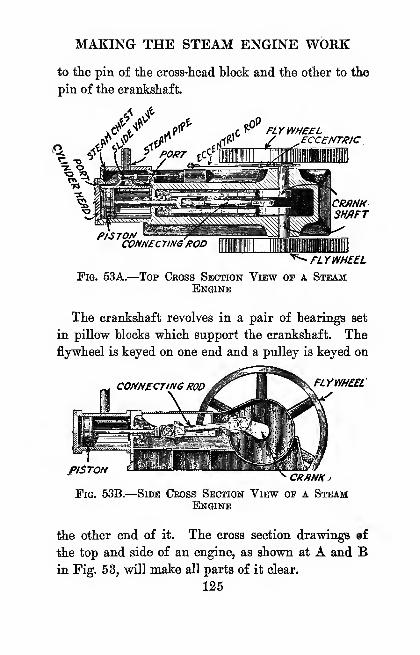
MAKING THE STEAM ENGINE WORK
to the pin of the cross-head block and the other to the
pin of the crankshaft.
S'\^,?^ f-^ FLYWHEEL
ECCENTRIC
CMNKSMflFT
PISTONCONNECTING ROD
^^FUyWHEELFig. 53A.
—
Top Cross Section View of a SteamEngine
The crankshaft revolves in a pair of bearings set
in pillow blocks which support the crankshaft. The
flywheel is keyed on one end and a pulley is keyed on
FLYWHEEL
PISTONCR/INKj
Fig. 53B.
—
Side Cross Section View of a SteamEngine
the other end of it. The cross section drawings af
the top and side of an engine, as shown at A and Bin Fig. 53, will make all parts of it dear.
125
THE AMATEUR MECHANIC
How the Engine Works.—In the picture shown
at C the steam chest is set above and away from the
cylinder simply so that you can see to better advan-
tage the ports and ducts that connect the steam chest
with the cylinder.
The slide valve, through its eccentric, and the pis-
ton, through its connecting rod, are coupled to the
STEflnPiPBSLIDE Y/iLYE
SLIDE VMYEROD
PO^T
EXH/JUSTPORT
PISTON
PORT
PI5TONR0D
CYLINDER
Fig. 53C.—Diagram Showing How a Steam EngineWOEKS
crankshaft so that they move in opposite directions.
The result is that, when the piston reaches either
end of the cylinder, the inlet port at the end nearest
the piston is open.
You will observe that the hollow in the slide valve
is always over the exhaust port, and that it always
covers the latter and one 'of the inlet ports at the
same time.
Now the way the engine works is like this : When126
/
MAKING THE STEAM ENGINE WORK
the steam under pressure from the boiler passes into
the steam chest, the slide valve is in one end of it
and the piston is in the opposite end of the cylinder.
Hence the port nearest to the piston is open and the
steam flows through it into the cylinder and pushes
the piston over to the other end.
When it reaches the port on this side it is open and
the steam rushing into the cylinder forces the piston
back again, which pushes the steam out of the other
inlet port and thence, by means of the slide valve,
out of the exhaust port into the open air.
Each forward movement of the piston pushes the
crankshaft half way round and each backward move-
ment pulls it the other half way round, thus making
a complete cycle, or one revolution.
The Latent Heat of Steam.—The above is the
simple mechanical action of the steam engine, but
there is another factor which, though it cannot be
seen, must be considered if the engine is to be an
efficient one, and that is the latent heat in the steam.
ISoi only does the sensible heat of the steam pro-
duce pressure but the latent heat also; by this is
meant that after the steam in the cylinder has been
cut off by the slide valve, its latent heat, that is, the
energy stored up in it, begins to change into energy
of motion, and this makes the steam expand and
keeps on pressing against the piston.
So to get all the power that is in the steam out of
it, the length of the stroke of the slide valve is so
adjusted that it cuts off the steam long before the pis-
127
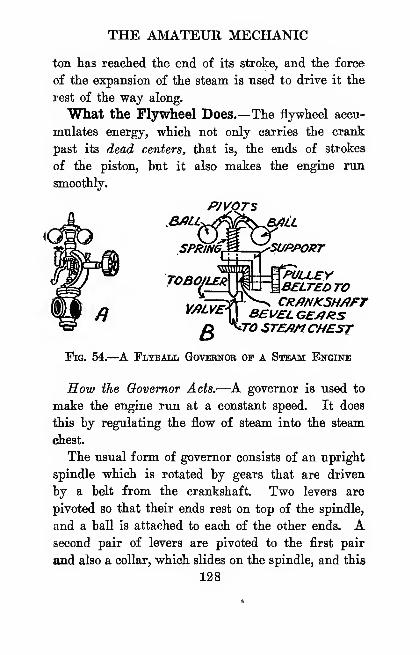
THE AMATEUR MECHANIC
ton has reached the end of its stroke, and the force
of the expansion of the steam is used to drive it the
rest of the way along.
What the Flywheel Does.—The flywheel accu-
mulates energy, which not only carries the crank
past its deibd centers, that is, the ends of strokes
of the piston, but it also makes the engine run
smoothly.
SUPPOKTSPRING, -!<•
TOBOtLE^^^^^^//^^^
i/zj/wrxr-KT ^ CRfiNKSHAFTiJ
B£V£LCE/J/ZSQ ^^O STEAMCHEST
Fig. 54.—^A Flyball Governor op a Steam Engine
How the Oovemor Acts.—^A governor is used to
make the engine run at a constant speed. It does
this by regulating the flow of steam into the steam
chest.
The usual form of governor consists of an upright
spindle which is rotated by gears that are driven
by a belt from the crankshaft. Two levers are
pivoted so that their ends rest on top of the spindle,
and a ball is attached to each of the other ends. Asecond pair of levers are pivoted to the first pair
and also a collar, which slides on the spindle, and this
128
MAKING THE STEAM ENGINE WORK
in turn is attached to the valve of the delivery pipe.
When the engine runs too fast, the balls fly apart,
which pulls the collar up and closes the valve. The
instant the steam is cut off the engine slows down
and the balls drop, thereby letting more steam into
the steam chest and then the engine runs faster. Agovernor is shown in cross-section at B in Mg. 54
and just as it is at A.
Packing for StufiSng Boxes.—Packing ^ is used
to prevent leakage around the piston and piston rod
and the connecting rod. Formerly hemp was largely
used for packing and the stuffing box was filled with
it. To reduce friction and wear on the packing and
rod, prepared packing was invented. This consists
of flax, asbestos and rubber cemented together and
lubricated with oil and graphite. It is quick and
easy to put in and insures against leaks and blowouts.
How to Figure the Horse Power of a Boiler.—
Since a boiler does not do mechanical work, the horse
power of it cannot be calculated in the same way as
in the case of an engine. It has been found by ex-
periment that, when 34.5 pounds of water are
changed into steam from and at a temperature of 212
degrees FaJirenheit, 1 holier horse power is produced.
A boiler horse power is the amount of steam power
needed to run an engine of 1 horse power.
It has also been found that, to change 34.5 pounds
'For kinds and prices write to TJie Crandall Packing Co.,
136 Liberty Street, New York City, or to TJie Johns-ManvUle
Co., 4l8t Street and Madison Avenue, New York City.
129
THE AMATEUR MECHANIC
of water into steam from and at 212 degrees, the
boiler must have 10 square feet of heating surface.
By heating surface is meant all of the boiler that the
fire actually strikes plus the total area of all the fire
tubes plus two-thirds the area of the smoke box.
Thus the heating surface required in a boiler to
make enough steam to run an engine, the horse power
of which you know, is
H.S. = H.P. X 10
where H.S. is the heating surface which you want
to find,
H.P. is the horse power of the engine which you
know and
10 is the number of square feet of heating surface
needed to generate 1 boiler horse power.
As an example, suppose you want to buy a boiler
for an engine of 2 horse power. Then
H.S. ^ 2 X 10, or 20 square feet of heating sur-
face is needed to generate enough steam to run your
engine at full load.
How to Figure the H.P. of Your Engine.—
You can find, roughly, the horse power of a single
cylinder steam engine by using this formiila
:
PXLXAXEH.P.
33,000
where H.P. is the horse power which you want to
find,
130
MAKING THE STEAM ENGINE WORK
P is the pressure of the steam on the piston and
this you get from the steam gauge of the boiler,
L is the length of the piston stroke in feet,
A is the area of the piston head in square inches
and is found by multiplying the radius of the
piston squared by 3.14,
E is the number of revolutions of the crankshaft
which you can find by a speed indicator, and
33,000 is the number of foot pounds which are
equal to 1 horse power.
Suppose, now, you want to find the horse power of
an engine whose cylinder is 4 inches in diameter;
the stroke of the piston is 8 inches; the pressure on
the piston is 40 pounds to the square inch and the
crankshaft makes 300 revolutions per minute.
The area of the cylinder is then 3.14 X R^ or
3.14 X 22 = 3.14 X 4 = 12.56 square inches; the
length of the stroke in feet is -^ foot or f foot or .66
foot.
Substituting these known values in the formula,
you have
40 X -66 X 12.56 X 300
33,000
99,480*^^ spoo == ^ ^°''^ P"^""-
CHAPTEK VIII
USING HOT AIR, GAS, GASOLINE AND OILENGINES
Hot air, gas, gasoline and oil engines furnish
sources of power that have many advantages for
home use over windmills, water wheels and steam en-
gines and, as each of the first named has its own
peculiar qualities, these will be cited as we go along.
The Hot Air Engine.—^While the hot air engine ^
is the most efiicient of all heat engines, it is only
used for pumping water, because of its small power
compared to its size.
The chief advantage of the hot air engine lies in
its absolute safety. Any boy or girl who can build
a fire or light a gas jet or a kerosene burner can run
the engine as well as a grown person. And, further,
a little fuel is all that is needed to have a supply
of water all the time.
How the Hot Air Engine Works.—The chief
parts of a hot air engine are (1) the displacement,
or expansion, cylinder, (2) the loose fitting transfer
piston, (3) the piston rod and connecting rod for it,
'Hot air engines axe sold by the Eider-Eriessoa Co., 20Murray Street, New York City.
132
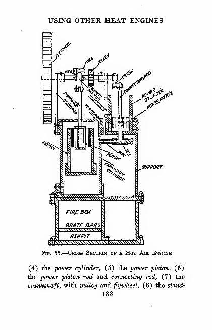
USING OTHER HEAT ENGINES
1^V
.StlPPOKT
Fig. 55.
—
Cross Section of a Hot Aie Engine
(4) the power cylinder, (5) the power piston, (6)
the power piston rod and connecting rod, (7) the
crankshaft, with pulley and flywheel, (8) the stand-
133

THE AMATEUR MECHANIC
ards, on which it is mounted, and (9) the fire hox, aH
of which are shown in the cross section view in
Fig. 55.
Now when a fire is built in the fire box it heats
the bottom of the expansion cylinder and, on giving
the flywheel a turn, the loose fitting transfer piston
in it moves down. This forces the hot air in the
bottom to go up and around it and into the top of
the*cylinder. On reaching the upper part the air is
cooled by a water jacket around the cylinder in which
water is flowing.
When the air is thus cooled it contracts, and, as
the expansion and power cylinders are connected,
the air contracts in the latter as well as in the former.
The power piston is pushed down by the force of
the air outside upon it, or the atmospheric pressure
as it is called.
Since the transfer piston and the power piston are
set at a straight angle, that is, an angle of 180 de-
grees, when the power piston is moving toward the
bottom the transfer piston moves toward the top.
This forces the cooled air back to the bottom of the
expansion cylinder, where the fire heats it once more.
When it is heated, the air expands, pushing the power
piston up, and the cycle starts aU over again.
Just bear in mind that the power is developed
only in the power cylinder by the hot air expanding
against the power piston first and, on cooling, by
the atmospheric pressure outside of it.
How to Use 9> Hot Air Engine.—When burning
134

USING OTHER HEAT ENGINES
coal, a good draft is needed. A 5-iiicli stove pip©
should he used for the smaller engines, and a 6-inch
pipe for the large engines, and a damper must be put
in the pipe in either case.
Chestnut size hard coal is the best fuel. This
should be fed into the fire box in small quantities
often in order to get an even heat and a steady speed.
Kerosene and gasoline burners can be bought of the
makers of hot air engines for burning these fuels.
The Gas Engine.—A gas engine is better than a
steam engine and boiler in that its first cost is
cheaper, it is smaller for the amount of power it
gives, it does not need to be looked after so closely,
and it is more economical to run.
Different from a steam engine, though, a gas en-
gine must be run at its full working speed before
it can be used to transmit its power to machinery.
Otherwise it will stall; this is because it is the sud-
den force of the explosion of the gas that drives the
piston to the end of the cylinder, while the heat
in the steam makes it expand and develop power
from the moment it enters the cylinders. Hence, a
gas engine must be started up before the load is
thrown on and this can be done either by shifting a
belt or by using a clutch of some kind.
The Parts of a Gas Engine.—A gas engine is
formed of the following principal parts, namely: (1)
the cylinder, (2) the piston and its connecting rod,
(3) the air and gas inlet valve, (4) the exhaust valve,
(5) the camshaft and cam, (6) the timing gears, (7)
135

THE AMATEUR MECHANIC
the crankshaft, on which are the pulley and flywheel,
and (8) the igniter.
In the type of gas engine in general use the
cylinder is open at one end, as shown in Fig. 56.
The piston is connected direct to the crankshaft hy
PLUG
EXHAUST
VMVI
INLETmLV£
P/5T0N
CONNECT/N&ROD
CAM
TIMINGGE/IR5
Fig. 56.
—
Cross Sectioit op a Gas Engine
a connecting rod, and this does away with the piston
rod, cross-head and cross-head guide.
The inlet valve is set in the closed end of the cylin-
der and works against a spiral spring. This lets the
juel mixture, as the gas and air which form the ex-
136

USING OTHER HEAT ENGINES
plosive charge is called, into the cylinder. A cam
opens it at the right instant to admit the fuel mix-
ture.
The exhaust valve is a valve in the head of the
cylinder and this is opened at the right time to let
out the humt gases by the cam on the camshaft, which
is geared to the crankshaft with a pair of bevel gears,
CYLINDEROF£NG//V£
^^"^"'^'-^/RON TUBE
HOTTUBE
TO Q/f3 SUPPLY
-ABUNSENBURNER
Tig. 57.
—
^Hot Tube Igniter fob a Gas Engine
or timing gears, as they are called. In automobile
engines both the inlet and the exhaust valves are
opened by cams on the camshaft.
The igniter which fires the fuel charge in the
cylinder is set in the head of the engine. There
are two kinds of igniters in general use and these are
(1) the hot tube igniter and (2) the electric spark
system.
The Hot Tube Igniter.—This is a very simple
13Y
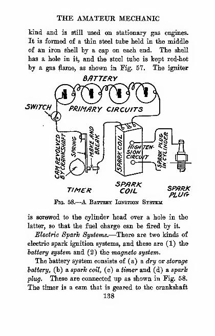
THE AMATEUR MECHANIC
kind and is still used on stationary gas engines.
It is formed of a thin steel tube held in the middle
of an iron shell by a cap on each end. The shell
has a hole in it, and the steel tube is kept red-hot
by a gas flame, as shown in Fig. 57. The igniter
B/ITTERV
SWITCH PRIM/1RY CIRCUITS
r?^
i0«j
1 n^^
TIMER5P/IRKCOIL SP/)RK
PLUCtFig. 58.—A Battery Ignition System
is screwed to the cylinder head over a hole in the
latter, so that the fuel charge can be fired by it.
Electric Spark Systems.—There are two kinds of
electric spark ignition systems, and these are (1) the
battery system and (2) the magneto system.
The battery system consists of (a) a dry or storage
battery, (b) a spark coil, (c) a timer and (d) a spark
plug. These are connected up as shown in Fig. 58.
The timer is a cam that is geared to the crankshaft
138
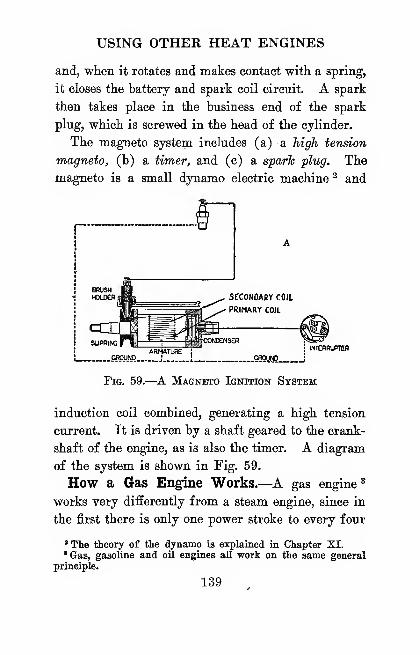
USING OTHER HEAT ENGINES
and, when it rotates and makes contact with a spring,
it closes the battery and spark coil circuit. A spark
then takes place in the business end of the spark
plug, which is screwed in the head of the cylinder.
The magneto system includes (a) a high tension
magneto^ (b) a timer, and (c) a sparh plug. The
magneto is a small dynamo electric machine ^ and
INIEBRUPKW
GROl!N0_;
Fig. 59.—A Magneto Ignition System
induction coil combined, generating a high tension
current. It is driven by a shaft geared to the crank-
shaft of the engine, as is also the timer. A diagram
of the system is shown in Fig. 59.
How a Gas Engine Works.—A gas engine*
works very differently from a steam engine, since in
the first there is only one power stroke to every four
' The theory of the dynamo is explained in Chapter XI.'Gas, gasoline and oil engines all work on the same general
principle.
139
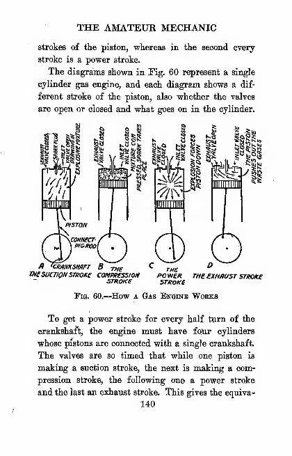
THE AMATEUR MECHANIC
strokes of the piston, whereas in the second every
stroke is a power stroke.
The diagrams shown in Fig. 60 represent a single
cylinder gas engine, and each diagram shows a dif-
ferent stroke of the piston, also whether the valves
are open or closed and what goes on in the cylinder.
n <CRANKSMFT B THEtH£SUCTIONSTROKE COMPItESSIOM
STROKE
THEPOWERSTROKE
THE EXHAUST STROKE
Tig. 60.—How a Gas Engine Works
To get a power stroke for every half turn of the
crankshaft, the engine must have fofur cylinders
whose pistons are connected with a single crankshaft.
The valves are so timed that while one piston is
making a suction stroke, the next is making a com-
pression stroke, the following one a power stroke
and the last an exhaust stroke. This gives the equiva-
140
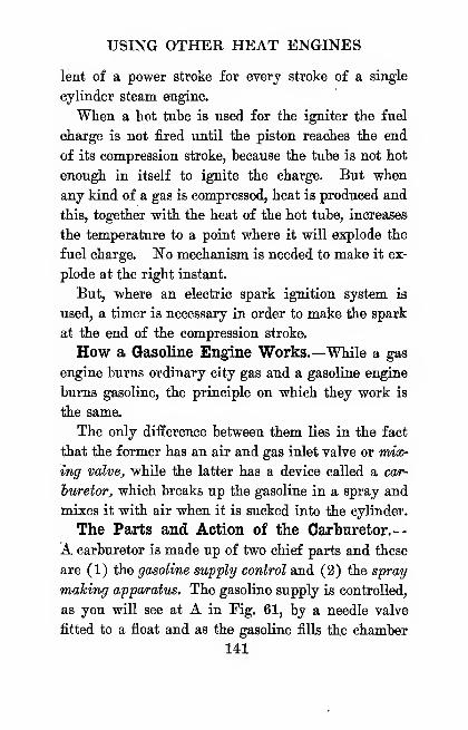
USING OTHER HEAT ENGINES
lent of a power stroke for every stroke of a single
cylinder steam engine.
When a kot tube is used for the igniter the fuel
charge is not fired until the piston reaches the end
of its compression stroke, because the tube is not hot
enough in itself to ignite the charge. But when
any kind of a gas is compressed, heat is produced and
this, together with the heat of the hot tube, increases
the temperature to a point where it will explode the
fuel charge. No mechanism is needed to make it ex-
plode at the right instant.
But, where an electric spark ignition system is
used, a timer is necessary in order to make the spark
at the end of the compression stroke.
How a Gasoline Engine Works.—While a gas
engine burns ordinary city gas and a gasoline engine
burns gasoline, the principle on which they work is
the same.
The only difference between them lies in the fact
that the former has an air and gas inlet valve or rmx-
ing valve, while the latter has a device called a car-
huretor, which breaks up the gasoline in a spray and
mixes it with air when it is sucked into the cylinder.
The Parts and Action of the Carburetor.—
A carburetor is made up of two chief parts and these
are (1) the gasoline supply control and (2) the spray
making apparatus. The gasoline supply is controlled,
as you will see at A in Fig. 61, by a needle valve
fitted to a fioat and as the gasoline fills the chamber
141
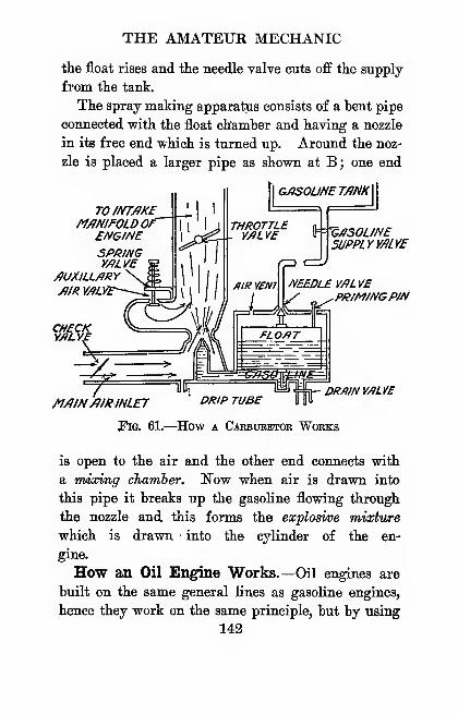
THE AMATEUR MECHANIC
the float rises and the needle valve cuts off the supply
from the tank.
The spray making apparatus consists of a bent pipe
connected with the float chamber and having a nozzle
in its free end vehich is turned up. Around the noz-
zle is placed a larger pipe as shown at B; one end
GASOUNETflNKX
TO INTAKEMANIFOLD OF
ENGINESPRINGVALVE
AUXILLARYAIH yALVt~--~~:B
CHECKYALVr
V^/ISOUNESUPPLY VALVE
NEEDLE VALVEPRIM/NGPIN
MAIN/fIRINLET '^'^'P ^fJ^^
Fig. 61.—How a Carbubetor Works
DRAIN VALVE
is open to the air and the other end connects with
a mixing chamber. Now when air is drawn into
this pipe it breaks up the gasoline flowing through
the nozzle and this forms the explosi/oe mixture
which is drawn > into the cylinder of the en-
gine.
How an Oil Engine Works.—Oil engines are
built on the same general lines as gasoline engines,
hence they work on the same principle, but by using
142

USING OTHER HEAT ENGINES
kerosene or crude oil for fuel these are safer and
more economical to run.
The fuel oil is kept in a supply tank, which should
be set below the level of the ground and outside of
the building where the engine is placed, as shown in
Fig. 62. The oil is pumped from the supply tank
into a fuel reservoir fixed to the cylinder of the en-
COMBUSTIONCH/tnBER
JNJECT/OMPUMP IMBP/C^TOP
/?/R SUCTIONP/P£
miNBEPRING
Fig. 62.
—
Oil Engine with Tank Underground
gine, and the oil in it is kept at a constant level by
an overflow pipe which carries the excess oil back to
the supply tank.
From the fuel reservoir the oil flows into the
•mixing valve which breaks up the kerosene, or crude
oil into a spray. The mixing valve is formed of a
needle valve which sets in a nozzle; the small end
of the nozzle is screwed into the head of the cylinder
and the other and large end is connected to the fuel
143
THE AMATEUR MECHANIC
reservoir. When the engine is running a small quan-
tity of the oil is drawn into the cylinder with the air
on the suction stroke of the piston, while a needle
valve regulates the amounit of oil that is taken into
the cylinder for each charge just as in an ordinary
carhuretor.
In the end of the air inlet pipe of the mixing
valve is a little damper called a butterfly valve. Byopening it more or less the right amount of air for
the amount of oil used to make the proper fuel mix-
ture for varying loads can be had. To do this a
governor, called a throttling governor, is connected
with the butterfly valve. This holds the speed of
the engine steady.
The inlet pipe of the mixing valve is also some-
times fitted with a nozzle attached to a supply of wa-
ter, which is thrown in a fine spray and drawn in
with the fuel mixture. The amount of water that is
taken into the cylinder is regulated by a needle valve.
The instant the water gets into the cylinder it is
converted by the heat into steam. This acts as a
cushion to break the violent force of the explosion
and makes the operation of the engine more economi-
cal without reducing the power. The water must
not be turned on until the engine has been running
for some time, and it must be shut off a little while
before the engine is stopped so that the cylinder will
be left dry.
To start an oil engine, especially where crude oil
is used, it is a good scheme to fill the reservoir with
144
USING OTHER HEAT ENGINES
gasoline first. By the time this is used up the en-
gine will he warm and work hetter.
Sizes and Power of Engines.—T^e Hoi Air En-gine.—The sizes of hot air engines are not hased
on the horse power which they develop, hut on the-
vertical heights to which they can pump water. Thus
an engine with a cylinder 5 inches in diameter will
pump water to a height of 50 feet; 6 inches to 75
feet; 8 inches to 125 feet; and 10 inches to 160
feet. For data of hot air engines write to the Rider-
Ericsson Engine Co., 20 Murray Street, New York.
City.
The Gas Engine.—Gas engines are built in all
sizes, from 1 horse power on up to any horse power
you want. Wherever there is a supply of natural
or artificial gas, you have a source of power that is.
at once cheap and requires a minimum of atten-
tion. Eor data, floor space required, speed, weight
and other data write to the Otto Gas Engine Works,
114 Liberty Street, New York City.
The Gasoline Engine.—^A gasoline engine is not
as economical to run as a gas engine but, where gas
is not available, it is the next best kind of a prime
mover. There are many makes of gasoline engines,
on the market, but to get a line on them write to the
Otto Gas Engine Works and the Eider-Ericsson En-
gine Co., as above; Fairbanks, Morse and Co., 30
Church Street, New York City, and Sears, Koebuck
& Co., Chicago.
145
THE AMATEUR MECHANIC
The Oil Engine.—The smallest oil engine that I
know of develops 2^ horse power, and from this little
xmit the sizes go on up to those large enough to run
a sugar refinery or to supply power for a submarine.
An oil engine uses about half as much kerosene as
the amount of gasoline used by a gasoline engine and,
as kerosene costs about half as much as gasoline,
it is obvious that it costs about a fourth as much to
run it. Crude oils are even cheaper than kerosene,
hut it is better to run small engines on kerosene than
on the heavier oils.*
For small oil engines write to Sears, Eoebuck &Co., Chicago, 111., and for the larger sizes get in
touch with Fairbanks, Morse and Co.
How to Pigfure the Horse Power of a Gas,
Gasoline or Oil Engine.—You can find about the
number of horse power a four stroke cycle engine will
give with this rule
:
D^ X NH.P. =
2.5
whpre H.P. is the horse power you want to know,
D^ is the bore or diameter of the cylinder squared,
N is the number of cylinders, and
2.5 is the coefficient and has been found accurate
for a piston speed of 1,000 feet per minute.
'Before buying any kind of an internal combustion engine"write to the National Board of Fire Underwriters, 76 WilliamSt., New York City, for a booklet called Segvlatuyns for the
Installation and Use of Internal Combustion Engine wMch will
be sent you free of charge.
146
USING OTHER HEAT ENGINES
Now suppose you have a 1 cylinder engine wkose
bore is 2f inches, then
:
2.752 X 1J-L.X .

CHAPTER IX
HOW TO HITCH UP POWER
Wherever you live you can easily have some kind
of power and, having it, you can with a little schem-
ing harness it up and make it pump water, wash
clothes, saw wood and do a hundred and one other
chores in and around the house and farm.
How to Use Wind Power.—While wind power
is intermittent and variahle, a good windmill prop-
erly fitted with transmission gears can be erected on
top of your barn, either by using a four post mast
or a steel tower, and running the vertical shaft down
inside of it.
The lower end of the vertical shaft is geared to a
horizontal shaft and this in turn has a pulley keyed
to it. The drive is then braced securely to hold it in
place, when it can be belted to whatever machine you
want it to run.
When I say any machine, I mean a machine which
does not require a constant speed, as, for instance,
a feed cutter, com sheUer, circular saw for sawing
wood, and the like.
About Changing Wind Power Into Electricity.—Many attempts have been made to generate elee-
148
HOW TO HITCH UP POWER
tricity by using a windmill as a prime mover, but as
the speed of the latter is so variable and the power
is so uncertain, it is not to be recommended, espe-
cially since the oil engine is so cheap to install and to
run.
How to Use Water Power.—If there is a stream
of water on your place, you have a source of power
that you can develop vsdth very little trouble and at
small initial expense. It will do all kinds of useful
work without cost and with practically no attention
after the plant is in operation.
All ordinary machinery can be belted directly to
the pulley on the shaft of a water wheel, or you
may have to use a pair of gears to speed up the drive
pulley. If you should want, however, to transmit
the power from the water to some distant point there
are two ways open for you to do it and these are (1)
by a rope drive and (2) by electric transmission.
To transmit power by a rope drive means simply
that you use an endless hemp rope instead of a belt
.
to connect the grooved pulley on the shaft of the
water wheel to a similar grooved pulley at the distant
place where you want to run the machinery. Where
power is to be transmitted over short distances and
light and heat are not needed at the other end, a
rope drive is both cheap to install and to keep up.
The distance to which a rope drive will work
satisfactorily, ranges anywhere from 10 to 175 feet,
while with carrying pulleys the power can be trans-
mitted to almost any distance.
149
THE AMATEUR MECHANIC
Should jou intend to install a rope transmission
of any kind, write to the American Manufacturing
Company, Noble and West Streets, Brooklyn, NewYork, for a copy of their Bltie Book of Rope Trans-
mission which they will send you gratis. In it you
will find out everything that is known about trans-
mission ropes and rope driving.
Where power is to be transmitted over consider-
able distances, the only feasible scheme is to belt or
gear a dynamo to the water wheel and convert the
energy of the head of water into current electricity.
If the water wheel can be fitted with a governor to
regulate the flow of water, the current can be used for
lighting, as it comes direct from the dynamo.
But for a lighting system it is always good practice
to hook up a storage battery to the dynamo and then
oull the current from the storage battery. This ar-
rangement not only gives a uniform current but,
when the battery is charged, you can shut down the
water wheel and dynamo, lock up the power house
and leave it to the battery to deliver the current
without fear of something going wrong.
How to Use Steam Power.—Steam is the ideal
power for running aU kinds of machinery in gen-
eral and dynamos in particular, because it is steady,
continuous and easy to regulate. Where gas, gaso-
line or oil can be used to fire the boiler, it takes but
little work to keep a steam power plant going; but
it isn't safe to let a boiler and a steam engine run
alone for any length of time.
150
HOW TO HITCH UP POWER
A dynamo can be belted to a steam engine and tbe
flywheel is often used for tbe pulley so that the
dynamo can be nm at a high enough speed without
using countershafting. If the engine is a high speed
one, the armature of the dynamo, that is, the re-
volving element, can be connected direct to the crank-
shaft of the engine.^
A storage battery need not be used to take the
current from the dynamo and then deliver it to the
lighting and heating appliances, but the current can
be used for lighting, and all other purposes you want
to put it to, as it is generated by the dynamo, that
is, where the engine is used only for running the
dynamo; where other machinery is driven by the
engine and there are variations in the load, or if
you want a current when the engine is not running,
or you want more current than the dynamo alone will
give at certain hours of the day or night then, of
course, you will have to install a storage battery.
Using Hot Air Power.—A hot air engine serves
admirably for ptimping water, running com shellers
and any kind of small machinery where a safe power
is needed for short periods of time. It is not a good
power, though, for driving a dynamo, even when a
storage battery is used in connection with it.
How to Use Oil and Gasoline Power.—An en-
gine burning kerosene is the cheapest and, next to
the hot air engine, the safest kind of a portable prime
»See Chapter XI.
151
THE AMATEUR MECHANIC
mover, not only in its first cost but in operation and
in upkeep.
You can't beat it as a handy power producer on
"tbe farm, for it will do nearly everything but herd
sheep and milk cows. But, if you want to generate
electric power for lighting, you must use a storage
battery between the dynamo and the lighting cir-
cuits.
A gasoline engine runs more smoothly than an oil
engine but, unless you have a four cylinder engine,
when you run the dynamo with it, if you do not run
any other machinery at the same time you can get
along without a storage battery.
In these days when so many second-hand ears have
been relegated to the scrap heap, you can often pick
up a car with a 20 or 30 horse power engine for as
many or a fewer number of dollars.
Having it, you can leave the engine on the frame
and mount the latter on a foundation of timbers, or
jou can loosen the bolts and take the engine off of
the frame and set it on timbers or on a concrete
foundation.
How to Use Your Automobile as a PowerPlant.—In these days when every well-to-do farmer
owns a motor car, it is easy to make it serve as a
power plant for driving light machinery, or even a
dynamo, in a pinch.
The drive is of the friction type, that is, the rear
wheels of a motor car set on a pair of rollers and,
when the engine is running, the friction between the
152
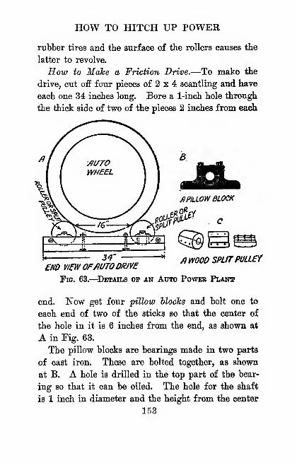
HOW TO HITCH UP POWER
rubber tires and the surface of the rollers causes the
latter to revolve.
How to Make a Friction Drive.—To make the
drive, cut off four pieces of 2 x 4 scantling and have
each one 34 inches long. Bore a 1-inch hole through
the thick side of two of the pieces 2 inches from each
^1 I .ffUTO \a
^PILLOW BLOCK
C
34- «/} WOOD SPLITPULLEY
£m VIEWOFfiUTODRIVE
Fig. 63.
—
^Details op an Auto Power Plant
end. ISTow get four pillow Hocks and bolt one to
each end of two of the sticks so that the center of
the hole in it is 6 inches from the end, as shown at
A in Fig. 63.
The pillow blocks are bearings made in two parts
of cast iron. These are bolted together, as shown
at B. A hole is drilled in the top part of the bear-
ing so that it can be oiled. The hole for the shaft
is 1 inch in diameter and the height from the center
153

THE AMATEUR MECHANIC
of it to the base is 1^ inches. Tou can buy them
for about Y5 cents apiece.*
After boring the holes for the bolts, round them,
out on one side so lihat the heads of the bolts will set
in flush with the surface. This done, lay one of the
sticks with the pillow block on it on one of the other
sticks, bore a i-inch hole through both of them 11
inches from each end, and then bolt the sticks to-
gether. These form the ends of the drive.
Now get two pieces of iron rod 1 inch in diameter
and 6 feet 2 inches long. Have a thread cut on each
end of each one 6 inches down ; screw a nut on each
end and then slip on a washer. Put the ends of
the rods through the holes in the ends in the sticks,
slip a washer over each one and screw a nut on the
end of each rod. This completes the frame.
The next thing is the roUers. You will either have
to get these turned or else buy split pulleys,^ that is,
pulleys which are cut in two so that they can be
bolted to a shaft, as shown at C. Get two lengths
of steel shaft 1 inch in diameter. Have one of them
6 feet long and the other 6 feet 6 inches long. Then
have a wood turner turn four hardwood rollers each
«f which is 6 inches in diameter and 12 inches long.
Next, bore a 1-inch hole down through the middle
'Luther H. Wightman, Milk Street, Boston, Mass., makesthem.
For further information and prices re wood split pulleys
write the Dodge Sales and Engineering Co., 21 Murray Street,
New York Cily.
154
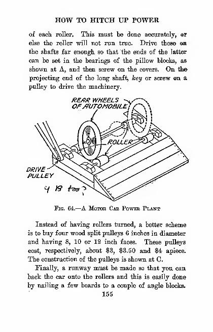
HOW TO HITCH UP POWER
of eacli roller. This must be done accurately, ®r
else the roller will not run true. Drive these Oia
the shafts far enough so that the ends of the latter
can be set in the bearings of the pillow blocks, as
shown at A, and then screw on the covers. On the
projecting end of the long shaft, hey or screw on a
pulley to drive the machinery.
RE/}/? WHEELS -^./—
v
OF/)UTOMOB/LEs r
DRIVEPULLEY
7 /9 tW^
Fig. 64.—^A Motor Car Power Plant
Instead of having rollers turned, a better scheme
is to buy four wood split pulleys 6 inches in diameter
and having 8, 10 or 12 inch faces. These pulleys
cost, respectively, about $3, $3.50 and $4 apiece.
The construction of the pulleys is shown at 0.
Finally, a run.way must be made so that you can
back the car onto the rollers and this is easily done
by nailing a few boards to a couple of angle blocks.
155

THE AMATEUR MECHANIC
Then your friction drive is ready to run as shown in
Fig. 64.
To find the horse power of the engine, see Chap-
ter VI; and to find the size and the speed of the
drive pulley needed to run a machine.at a given speed,
se3 Chapter IV.
CHAPTEE X
INSTALLING A HOME ICE-MAKING MACHINE
While it is easy to produce intense heat, it is quite
another matter to make intense cold, especially on
a small scale. Hence, ice is cut in the winter, stored
in ice houses until summer and, when the ther-
mometer is in the neighborhood of lOO-j- in the shade,
it is delivered by the ice man at fabulous prices to
the sweltering householder.
What Cold Is.—When we say a thing is cold wemean that it has a temperature which is lower than
that of the normal, or standard, temperature, which
is generally taken to be the temperature of the humanbody, namely, 98f degrees Fahrenheit.
The standard of low temperature is the freezing
point of water. This, as you found "in Chapter IV,
is 32 degrees on the Fahrenheit thermometer and
degree on the centigrade thermometer. But the
freezing point of a substance does not by any means
show that there is no more heat in it. The tem-
perature at which a body really loses all of its heat
is called the absolute zero and this is 273 degrees
colder than the freezing, or point, on the centigrade
scale.
15-7
THE AMATEUR MECHANIC
How Cold is Produced.—There is only one wayby which cold can be produced and this is by evaporor
tionj to do this a liquid must be used or if a gas is
used it must be condensed into a liquid first, and in
all ice-making machines both of these principles are
combined and used.
Cooling hy Evaporation.—^In physics evaporation
means that a vapor is formed on and given off by the
exposed surface of water, or any other liquid, which
has a temperature below the boiling point. In coun-
tries where the heat is intense, drinking water is kept
cool by putting it in unglazed earthen jars, which
are porous, and set in the shade where the wind will
blow on them.
As the water seeps through the pores of the jar
and reaches the surface, the wind evaporates it and
this rapid evaporation keeps the water cool. An ex-
periment to illustrate cooling by evaporation is to
put a few drops of alcohol, or, better, ether, in the
open palm of your hand, when it will evaporate very
fast, and you will feel it get quite cold.
What Condensation Is.—^In physics condensation
means that a gas or vapor is changed to a liquid.
Now, there are two ways a gas or vapor can be
liqiiefied and these are (1) by cooling it and (2) by
compressing it, and both of these processes are used
in ice-making machines.
For experimental purposes and making ice cream,
a freezing mixture can be made by mixing 1 part of
salt with 3 parts of cracked ice, and this will produce
158
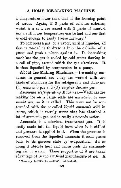
A HOME ICE-MAKING MACHINE
a temperature lower than that of the freezing point
of water. Again, if 3 parts of calcium chloride,
which is a salt, are mixed with 2 parts of cracked
ice, a still lower temperature can be had and one that
is cold enough to easily freeze mercury.^
To compress a gas, or a vapor, until it liquefies, aH
that is needed is to draw it into the cylinder of a
pump and push a piston against it. In ice-making
machines the gas is cooled by cold water flowing in
a coil of pipe, around which the gas circulates. It
is then liquefied by compression in a pump.
About Ice-MaMug Machines.—Ice-making ma-
chines in general use today are worked with two
kinds of chemicals for the refrigerants and these are
(1) ammonia gas and (2) svlphur dioxide gas.
Ammonia Refrigerating Machines.—^Machines for
making ice on a large scale use ammonia, or am-
monia gas, as it is called. This must not be eon-
founded with the so-called liquid ammonia sold in
stores, which is merely water that has absorbed a
lot of ammonia gas and is really ammonia water.
Ammonia is a colorless, transparent gas. It is
easily made into the liquid form when it is chilled
and pressure is applied to it. When the pressure is
removed from the liquefied ammonia it soon passes
back to its gaseous state by evaporation. Jn so
doing it absorbs heat and hence cools the surround-
ing air or water. These properties of it are taken
advantage of in the artificial manufacture of ice. A•Mercury freezes at —39.5° Fahrenheit.
159
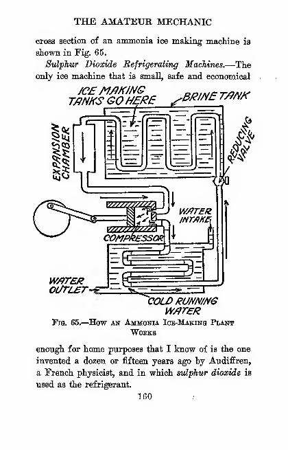
THE AMATEUR MECHANIC
cross section of an anunoma ice making machine is
shown in Fig. 65.
Sulphur Dioxide Refrigerating Machines.—Theonly ice machine that is small, safe and economical
.3/^/NBT/?/V/CT/JNKS GOHERE
VMTER
Fig. 65.—^How an Ammonia Ice-Making PlantWOEKS
enough for home purposes that I know of is the one
invented a dozen or fifteen years ago by Audiffren,
a French physicist, and in which sulphur dioxide is
used as the refrigerant.
160 /

A HOME ICE-MAKING MACHINE
Sulphur dioxide is a gas that liquefies muoh easier
tban anunonia gas, in fact all that is needed to liquefy
it is to set the vessel containing it in a freezing mix-
ture made of ice and salt, as previously described.
Sulphur dioxide also liquefies at a much lower pres-
sure than ammonia and has a much lower working
pressure.
Different from the ammonia ice-making machine
in which there is a leakage of the refrigerant^ as the
ammonia is called, through the stufiing boxes and pipe
joints, the Audiffren sulphur dioxide machine has its
refrigerant hermetically sealed, that is, sealed air-
tight, in the dumbbell which forms the rotating part
of the machine.
The machine,^ which is shown in cross section in
Fig. 66, consists of a shaft with a pulley on one end,
a refrigerator drum, or hollow shell, on the other end
and a compressor drum, or hollow shell, set on the
shaft between them. This revolving element, or
dumbhellj so called from its shape, rests on two bear-
ings, one on each side of the middle drum.
The compressor, as the pump is called, hangs on
the shaft and it is held by a heavy lead weight, so
that it always keeps an upright position. The piston
which works in the cylinder of the pump is moved to
and fro by means of a connecting rod fixed to an
eccentric on the shaft.
Above the cylinder and the shaft is a reservoir for
' This ice machine is sold by The Johns-ManviUe Co., 4l8t Stand Madison Ave., New York City.
161
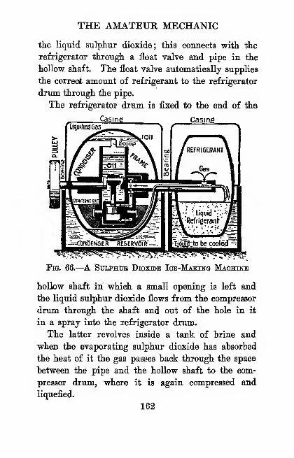
THE AMATEUR MECHANIC
the liquid sulphur dioxide; this connects with the
refrigerator through a float valve and pipe in the
hollow shaft. The float valve automatically supplies
the correct amount of refrigerant to the refrigerator
drum through the pipe.
The refrigerator drum is fixed to the end of the
Casing casing.
Fig. 66.—^A ^tilphub Dioxide Ice-Making Machine
hollow shaft in which a small opening is left and
the liquid sulphur dioxide flows from the compressor
drum through the shaft and out of the hole in it
in a spray into the refrigerator drum.
The latter revolves inside a tank of brine and
when the evaporating sulphur dioxide has absorbed
the heat of it the gas passes back through the space
between the pipe and the hollow shaft to the com-
pressor drum, where it is again compressed and
liquefied.
162
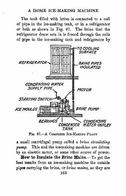
A HOME ICE-MAKING MACHINE
The tank filled with brine is connected to a coil
of pipe in the ice-making tank, or in a refrigerator
or both as shown in Fig. 67. The brine that the
refrigerator drum sets in is forced through the coils
of pipe in the ice-making tank and refrigerator by
REFmG£/iATOR^
fnW
THE AMATEUR MECHANIC
called, must be well insulated, that is, covered, to
prevent them from absorbing heat. The better they
are insulated the smaller will be the expense of mak-
ing the ice. The best insulation for brine mains is
cork. This can be bought of the Armstrong Cork
Company, 50 Church St., l^ew York City, or of the
Johns-Manville Company, 41st St. and Madison Ave.,
New York City.
How to Build a Refrigerator.—The refrigera-
tor must also be thoroughly well insulated. If you
will build one of the following materials in the order
named, you will have one that will keep out heat
as well or better than any you could buy.
The materials are named in the order in which
they are built up from the outside to the inside of
the refrigerator. Begin with (1) one layer of ^-inch
boards for the outside and (2) cover this on the in-
side with waterproof paper; (3) put on a layer of
pure sheet cork 2 or 3 inches thick; (4) on this put
another layer of waterproof paper; (5) then a layer
of ^inch boards, and, finally, (6) line it with tVinch thick opaque glass, or thin sheet enameled steel.
Some Facts About Ice Making.—The follow-
ing facts are interesting in connection with the mak-
ing of ice. (1) Water that has been distilled will
freeze clear, but it is not at all necessary to use dis-
tilled water to get nearly pure ice.
(2) When raw water is frozen it tends to force
the impurities in it to the center. The slower the
water is frozen the clearer the ice will be. (3) If
164
A HOME ICE-MAKING MACHINE
the water is stirred or otherwise agitated while it is
freezing, the quicker and more surely will the im-
pure matter he forced to the center of the cakes
when it can be removed. Agitation helps to form
clear, solid cakes of ice. ,
(4) The rate at which ice freezes decreases direct-
ly with the thickness of that which is already frozen.
This being true, it follows that the time it takes
to freeze a cake of ice increases in proportion to the
square of the thickness of that to be frozen.
(5) To malie raw water ice, fill the cans with the
water and agitate it until it is partly frozen. Then
draw off the remaining water. This will carry off
most of the impurities that have been frozen out and
into it. Fill the can with fresh water and agitate
it while it is freezing as before.
What It Costs to Make Ice.—To find the dif-
ference in the cost of natural ice and mechanically
made ice, you must include in the former (1) the
cost of harvesting, which means the labor of cutting
and storing it; (2) the melting and other wastage of
it; and (3) the amount left over at the end of the
season.
The cost to make ice with an ice machine varies
within wide limits, too, but in any case it is based on
the cost of (1) coal, (2) labor, (3) the refrigerant
used, (4) water and (5) the power that is used,
loss of oil, etc.
CHAPTEK XI
ELECTRICITY IN THE HOME AND ON THE FAEM
As you have seen from what has gone hefore, you
can have power at very little expense wherever you
live and, having it, you can convert it into electricity
without the slightest trouhle.
Now, while electaricity is a secovdary power, that
is, it must first he generated by some other power
such as water, steam or gas, you can do with it that
which you cannot do with any of the others, that is,
use it for light, heat and power at one and the same
time.
What to Know About Electricity.—It is easy
to imderstand how a current of electricity acts and
works if you know just three things about it, and
these are (1) that it has quantity, or current strength,
as it is called, (2) that it has pressure, or electromo-
tive force, as it is termed, to drive the current along,
and (3) that the wire in which the current is flowing
has resistance, that is, it opposes the flow of the cur-
rent.
From this you vrill observe that an electric cur-
rent behaves very like a current of water flowing
through a pipe, hence, when you want to know how166
ELECTRICITY IN THE HOME
the former would act lander certain conditions, just
consider what the latter would do and you will come
pretty close to the right solution of the problem.
You must be careful, though, not to carry this hydrau-
lic analogue too far.
Current Strength and the Ampere.—^When the
poles of a battery, or a dynamo, are connected with a
wire, or circuit as it is called, a current flows from
the positive, or + side, to the negative, or — side.
Now the quantity of electricity, or current
strength, or just current for short, as it is called,
flowing in a wire or circuit depends on the pressure,
or electromotive force, that is driving the current
along the wire, and the resistance of the latter.
The greater the pressure, the larger the current
that can be forced to flow through the wire; on the
other hand, the higher the resistance of the wire, the
smaller the current that can be forced through it.
To measure the amount of current that is flowing
through a wire, or circuit, a unit called the atfipere
is used. 1 ampere is the amount of current that 1
volt of electromotive force will drive through a wire
having a resistance of 1 ohm. The amount of cur-
rent is measured by an instrument called an am-
meter.
Electromotive Force and the Volt.—The pressure
that forces electricity along a wire, or electromotive
force, is measured by a unit called the volt. A volt
is the electromotive force needed to drive 1 ampere
through a wire having a resistance of 1 ohm.
16Y
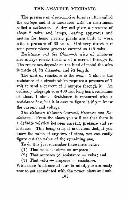
THE AMATEUR MECHANIC
The pressure or electromotive force is often called
the voltage and it is measured with an instrument
called a voltmeter. A dry cell giveS a pressure of
about 2 volts, and lamps, heating apparatus and
motors for home electric plants are built to work
with a pressure of 32 volts. Ordinary direct cur-
rent power plants generate current at 110 volts.
Resistance and the Ohm.—^A wire of whatever
size always resists the flow of a current through it.
The resistance depends on the kind of metal the wire
is made of, its diameter and its length.
The unit of resistance is the ohm. 1 ohin, is the
resistance of a circuit which requires a pressure of 1
volt to send a current of 1 ampere through it. An•ordinary telegraph wire 400 feet long has a resistance
of about 1 ohm. Resistance is measured with a
resistance iox, but it is easy to figure it if you knowthe current and voltage.
The Relation Between Current, Pressure, and Re-
sistance.—^From the above you will see that there is
a definite relation between current, pressure and re-
sistance. This being true, it is obvious that, if you
know the value of any two of them, you can easily
figure out the value of the remaining one.
To do this just remember these three rules
:
(1) That volts -r- ohms = amperes;
(2) That amperes X resistance = volts; and
(3) That volts -^- amperes = resistance.
With these fundamental laws in mind, you are ready
now to get acquainted with the power plant and sub-
168
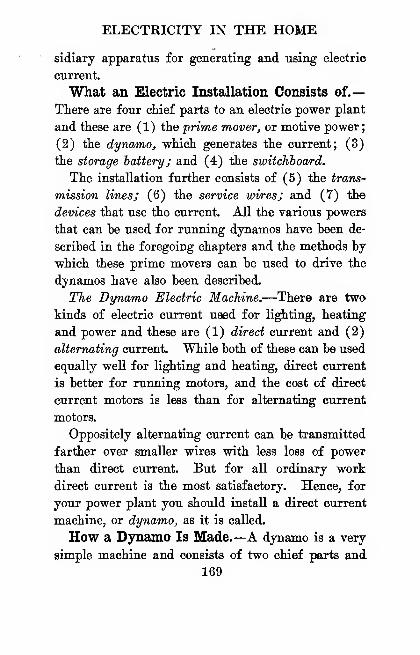
ELECTRICITY IN THE HOME
sidiary apparatus for generating and using electric
current.
What an Electric Installation Consists of.—
There are four chief parts to an electric power plant
and these are (1) the prime mover, or motive power;
(2) the dynamo, which generates the current; (3)
the storage batteryj and (4) the switchboard.
The installation further consists of (5) the trans-
mission lines; (6) the service wiresj and (7) the
devices that use the current. All the various powers
that can be used for running dynamos have been de-
scribed in the foregoing chapters and the methods by
which these prime movers can be used to drive the
dynamos have also been described.
The Dynamo Electric Machine.—There are two
kinds of electric current used for lighting, heating
and power and these are (1) direct current and (2)
alternating current. While both of these can be used
equally well for lighting and heating, direct current
is better for running motors, and the cost of direct
current motors is less than for alternating current
motors.
Oppositely alternating current can be transmitted
farther over smaller wires with less loss of power
than direct current. But for all ordinary work
direct current is the most satisfactory. Hence, for
your power plant you should install a direct current
machine, or dynamo, as it is called.
How a Dynamo Is Made.—A dynamo is a very
simple machine and consists of two chief parts and
169
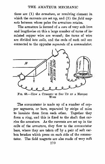
THE AMATEUR MECHANIC
these are (1) the armature^ or revolving element in
which the currents are set up, and (2) the field mag-
nets hetween whose poles the armature rotates.
The armature is formed of a core of very soft iron
and lengthwise on this a large number of turns of in-
sulated copper wire are wound; the turns of wire
are divided into coils, and the ends of each coil are
connected to the opposite segments of a commutator.
Fig. 68.—How a Cuebent is Set Up in a MovingWire
The commutator is made up of a number of cop-
per segments, or bars, separated by strips of mica
to insulate them from each other. Together they
form a ring, and this is fixed to the shaft that car-
ries the armature. As the currents are set up in the
coils of the armature, they flow to the commutator
bars, where they are taken off by a pair of soft car-
bon brushes which press on each side of the commu-
tator. The field magnets are also made of very soft
lYO

ELECTRICITY IN THE HOME
iron and these are wound with insulated copper wire.
How a Dynamo Generates Current.—A simple
way to show how a dynamo generates a current is
to connect the ends of a oopper wire with a galvanom-
eter and move the wire quickly across the pole of a
magnet, as shown at A in Fig. 68.
The instant you do this the needle of the galvanom-
F/ELDM/)GNET
FIELDMAGNET
LOOP OFW/RE
WIRE c/Rcuir
Fig. 69.
—
The Phinciple op the Dynamo
eter will swing and this shows that a current is flow-
ing in the circuit; further, this experiment shows
that whenever a wire cuts the magnetic lines of force,
the latter are changed into an electric current which
is set up in the wire.
To make the wire cut the lines of magnetic force,
form it into a loop, as shown in Fig. 69, and fix it to
a spindle with a crank. When you turn the crank
in the direction of the arrow, currents will be coa-
171
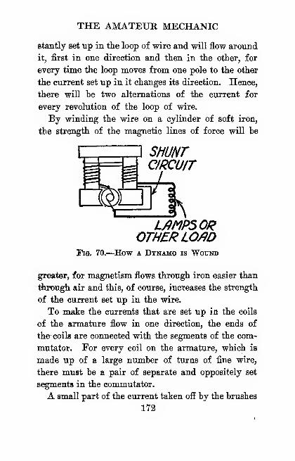
THE AMATEUR MECHANIC
stantly set up in the loop of wire and will flow around
it, first in one direction and then in the other, for
every time the loop moves from one pole to the other
the current set up in it changes its direction. Hence,
there will be two alternations of the current for
every revolution of the loop of wire.
By winding the wire on a cylinder of soft iron,
the strength of the magnetic lines of force will be
SHUNTCIRCUIT
L/IMP50ROTHER LO/ID
Fig. 70.—How a Dynamo is Wound
greater, for magnetism flows through iron easier than
Uunugh air and this, of course, increases the strength
of the current set up in the wire.
To make the currents that are set up in the coils
of the armature flow in one direction, the ends of
the- coils are connected with the segments of the com-
mutator. For every coil on the armature, which is
made up of a large number of turns of fine wire,
there must be a pair of separate and oppositely set
segments in the commutator.
A small part of the current taken off by the brushes
172
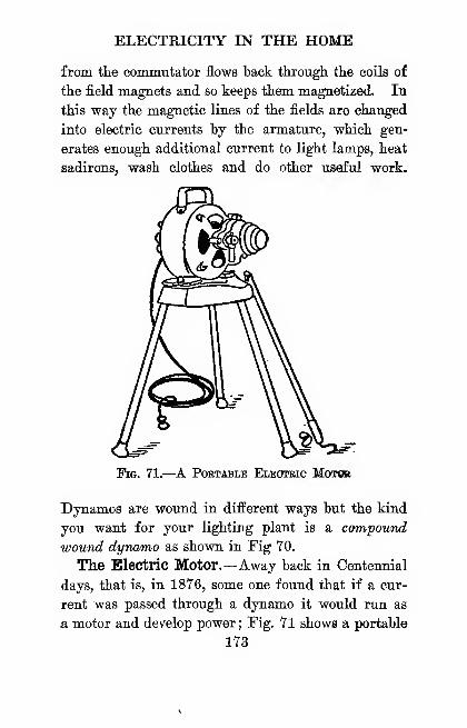
ELECTRICITY IN THE HOME
from the commutator flows back through the coils of
the field magnets and so keeps them magnetized. In
this way the magnetic lines of the fields are changed
into electric currents by the armature, which gen-
erates enough additional current to light lamps, heat
sadirons, wash clothes and do other useful work.
Fig. 71.—^A Portable Eleoteic Motob
Dynamos are wound in different ways but the kind
you want for your lighting plant is a compound
wound dynwmo as shown in Fig YO.
The Electric Motor.—Away back in Centennial
days, that is, in 1876, some one found that if a cur-
rent was passed through a dynamo it would run as
a motor and develop power; Fig. 71 shows a portable
173
THE AMATEUR MECHANIC
motor capable of doing all kinds of work wherever
you want it done. To find the horse power an elec-
tric motor is using or a dynamo is delivering in cur-
rent, or a lamp or any other piece of electrical ap-
paratus takes, you should know first that the unit
of eUdric power is the watt and that there are 746
watta in 1 horse power.
To find the number of watts that is being generated
or used, all you have to do is to multiply the cur-
rent (amperes) by the pressure (volts)
or W = C X E
Then to find the horse power, use this formula
:
CXEH.P. =-
746
where H.P. is the horse power and is what you
want to find,
C is the current in amperes which you know,
E is the pressure in volts which you also know and
746 is the number of watts in 1 H.P.
Thus, if a 30 volt motor takes 6 amperes to run
it, substitute these values for those in the formula
to find the horse power developed thus
:
6 X 30H.P. =
or H.P.
746
180
746
or H.P. = .23 or very nearly J horse power,
174
ELECTRICITY IN THE HOME
How a Storage Battery Is Made.—^When two
lead plates are set in a jar of dilute sulphuric acid,
they form the simplest kind of a storage battery.
To charge a storage battery, a dynamo must be
connected with the lead plates and after it is charged
it will, in turn, deliver a constant current. To make
the lead plates more active, holes, or grooves, are
drilled or cut in them, as shown in Fig. Y2. The
negative plates are filled with spongy lead, and those
in the positive plates are filled with red oxide of lead.
A storage battery cell is built up of several plates
and each positive plate is set between two negative
plates. This is to keep the positive plate from warp-
ing, or huchling, as it is called, when the cell is
charged. A separator made of thin wood is placed be-
tween each positive and negative plate to keep them
the right distance apart. A number of the plates, or
groups, are then assembled into an element and set
into a jar containing the electrolyte, that is, a solu-
tion made of pure sulphuric acid and water.
All of the negative plates of a group are connected
together and all of the positive plates of a group
are connected together and all together they form an
element. Finally, an element in a jar filled with
electrolyte forms a cell, see Fig. 72, and two or
more cells connected together constitute a battery.
How to Use a Storage Battery.—Bear in mind
these two things, first: (1) that the number and the
size of the lead plates determine the amount of cur-
rent, or amperes, that the battery can be eharged
175

-POSITIVE
NE&flmE STRfiP
NiGflTlVEGROUP POSITiyE
GROOP
WOOPSEPmffTOR
PUTTING THEELEMENTlNjm.
WOOD^EPffRfiTOR
SUPPING IN THESEPflRflTO/ZS
Tig. 72.-
THE C£lLREftOrPORi/SjE
The Pabts op a Storage Battery
176
ELECTRICITY IN THE HOME
"with and will deliver and (2) that each cell has an
electromotive force, or voltage, of 2 volts, regardless
of the number of plates and the sizes of them. For
this reason the voltage is constant and the current
varies according to the load.
A storage battery for home lighting and power
circuits is made up of 16 cells, and these give 32
volts. But batteries can be had in several different
sizes, so that you can store up enough current to
light as many lamps at one time or for as long a
time without recharging it as you may need.
A battery is rated by the number of ampere hours
it will give. Thus, a 44 ampere hour battery will
deliver 1 ampere for 44 hours or 44 amperes for 1
hour or any mean, that is, the equivalent of these
figures, according to the load it must take care of.
As an example, a 32-volt, 16-candle power lamp
takes about If amperes to light it. Hence you can
keep 1 lamp lit on a 44 ampere hour battery for 25
hours, or 5 lamps of the same candle power for 5
hours, without recharging the battery.
The Switchboard and Its Instruments.—The
next thing is to connect the dynamo with the storage
battery and lights and other apparatus that uses the
current. This is done through the switchboard.
This is a panel of hard fiber, or better, of slate,
and it has on it (1) a voltmeter, (2) an ammeter,
(3) a rheostat, (4) an automatic cutout, (5) a dovr
hle-throw switch and (6) a pair of enclosed fuses.
177
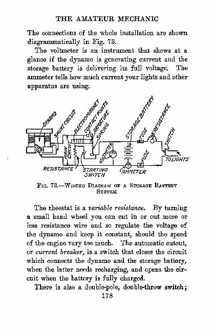
THE AMATEUR MECHANIC
The connections of the whole installation are shown,
diagrammatically in Fig. 73.
The voltmeter is an instrument that shows at a
glance if the dynamo is generating current and the
storage battery is delivering its full voltage. The
ammeter tells how much current your lights and other
apparatus are using.
//V
TOLIGHTS
/?£SJSTmC£' ST/)RTINGSWITCH
Fig. 73.
—
Wiring Diagram oi" a Storage BatterySystem
The rheostat is a variable resistance. By turning
a small hand wheel you can cut in or out more or
less resistance wire and so regulate the voltage of
the dynamo and keep it constant, should the speed
of the engine vary too much. The automatic cutout,
or current hreaker, is a switch that closes the circuit
which connects the dynamo and the storage battery,
when the latter needs recharging, and opens the cir-
cuit when the battery is fully charged.
There is also a double-pole, double-throw switch;
178
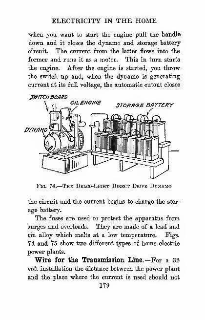
ELECTRICITY IN THE HOME
when you want to start the engine pull the handle
down and it closes the dynamo and storage battery
circuit. The current from the latter flows into the
former and runs it as a motor. This in turn starts
the engine. After the engine is started, you throw
the switch up and, when the dynamo is generating
current at its full voltage, the automatic cutout closes
SWITCHBOARDOILENGJNE 3T0RflGB BATTERY
DYNfiMO
Fig. 74.
—
The Delco-Light Direct Drive Dynamo
the circuit and the current begins to charge the stor-
age battery.
The fuses are used to protect the apparatus from
surges and overloads. They are made of a lead and
tin alloy which melts at a low temperature. Figs.
74 and 75 show two different types of home electric
power plants.
Wire for the Transmission Line.—For a 32
volt installation the distance between the power plant
and the place where the current is used should not
179

THE AMATEUR MECHANIC
be more than 500 feet, because there is a dto-p of
voltage on the line no matter how large the wires
forming it may be.
Where a greater distance than 500 feet is to be
covered, a 110 volt installation must be used. Bare
copper or aluminum wire,^ or insulated copper wire.
sw/rcH jj-iBOfiRD CotT'
'0/L ENGINEFig. 75.
—
The Morse Fairbanks BELT-DErvEN
Dynamo
supported on porcelain or glass petticoat insulators,*
can be used for the transmission lines.
Ovi, and Inside Wiring.—For wires that are to
run between buildings, use approved weatherproof
wire; and for inside wiring use rubber-covered wire.
' For prices send to the Aluminum Company of America, 120Broadway, New York City.
'For prices write to the Manhattan Electrical Company,Park Place, New York Cily.
180
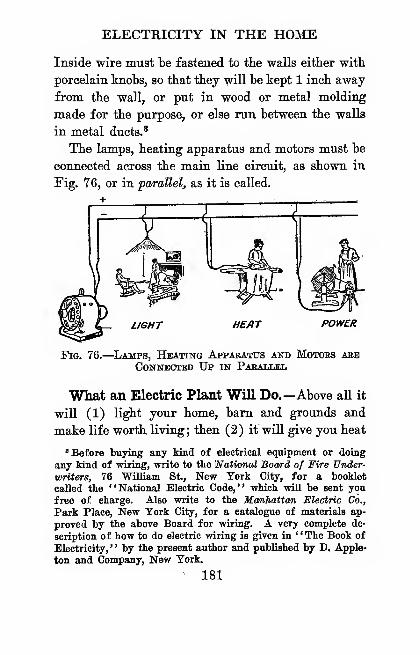
ELECTRICITY IN THE HOME
Inside wire must be fastened to the walls either with
porcelain knobs, so that they ynll be kept 1 inch away
from the wall, or put in wood or metal molding
made for the purpose, or else run between the walls
in metal ducts.*
The lamps, heating apparatus and motors must be
connected across the main line circuit, as shown in
Fig. 76, or in parallel, as it is called.
-z
POWER
Fig. 76.
—
^Lamps, Heating Apparatus and Motoes areConnected Up in PaeaUjEL
What an Electric Plant Will Do.—Above all it
will (1) light your home, bam and grounds and
make life worth living; then (2) it will give you heat
'Before buying any kind of electrical equipment or doing
any kind of wiring, write to the lATottoTioJ Boa/rd of Fire XJnder-
writers, 76 William St., New York City, for a booklet
called the "National Electric Code," which wiU be sent you
free of charge. Also write to the Manhattan Electric Co.,
Park Place, New Tork City, for a catalogue of materials ap-
proved by the above Board for wiring. A very complete de-
scription of how to do electric wiring is given in '' The Book of
Electriciiy, '' by the present author and published by D. Apple-
ton and Company, New Tork.
^ 181
THE AMATEUR MECHANIC
for curling irons, flatirons, percolators, toasters and
other utensils and conveniences; (3) it will give you
power to run a tumble churn, coffee mill, cream sepa-
rator, dishwasher, grindstone, horse clippers, ice-
cream freezer, massage vibrator, meat grinder, milk-
ang machine, pumps, sewing machine, vacuum cleaner,
washing machine, milking machine, etc. ; and, finally
(4) all of these things make for a life which will keep
the boys and girls at home and which you and your
wife cannot afford to be without.
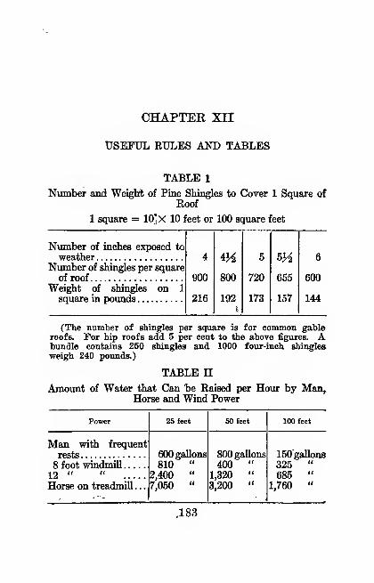
CHAPTEE XII
USEFUL RULES AND TABLES
TABLE 1
Number and WeiglA of Pine Shingles to Cover 1 Square ofRoof
1 square = 10]X 10 feet or 100 square feet
Number of inches exposed to
weatherNumber of shingles per square
ofroof 900 800 720 655 600Weight of shingles on 1
square in pounds 216 192 173 157 144
(The number of shingles per square is for common gableroofs. For hip roofs add 5 per cent to the above figures. Abundle contains 250 shingles and 1000 four-ineh shingles
weigh 240 pounds.)
TABLE nAmoimt of Water that Can "be Raised per Hour by Man,
Horse and Wind Power
4
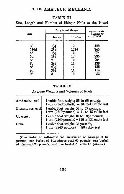
THE AMATEUR MECHANIC
TABLE III
Size, Length and Number of Shingle Nails to the Pound
Size
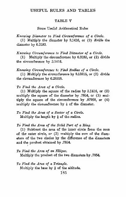
USEFUL RULES AND TABLES
TABLE V
Some Useful Arithmetical Rules
Knowing Diameter to Find Circumference of a Circle.
(1) Multiply the diameter by 3.1416, or (2) divide the
diameter by 0.3183.
Knowing Circumference to Find Diameter of a Circle.
(1) Multiply the circumference by 0.3183, or (2) divide
the circumference by 3.1416.
Knowing Circumference to Find Badms of a Circle.
(1) Multiply the circumference by 0.15915, or (2) divide
the circumference by 6.28318.
To Find the Area of a Circle.
(1) Multiply the square of the radius by 3.1416, or (2)
multiply the square of the diameter by .7854, or (3) mul-
tiply the square of the circumference by .07958, or (4)
multiply the circumference by i of the diameter.
To Find the Area of a Sector of a Circle.
Multiply the length by i of the radius.
To Find the Area of the Solid Part of a Bing.
(1) Subtract the area of the inner circle from the area
of the outer circle, or (2) multiply the sum of the diam-
eters of the two circles by the difference of the diameters
and the product obtained by .7854.
To Find the Area of an Ellipse.
Multiply the product of the two diameters by .7854.
To Find the Area of a Triangle.
Multiply the base by J of the altitude.
185
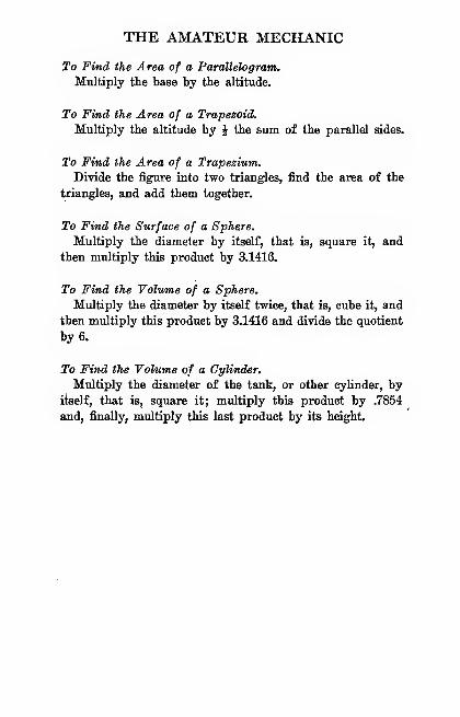
THE AMATEUR MECHANIC
To Find the Area of a Parallelogram.
Multiply the base by the altitude.
To Find the Area of a Trapezoid.
Multiply the altitude by J the sum of the parallel sides.
To Find the Area of a Trapezium.
Divide the flgnire into two triangles, find the area of the
triangles, and add them together.
To Find the Surface of a Sphere.
Multiply the diameter by itself, that is, square it, and
then multiply this product by 3.1416.
To Find the Volume of a Sphere.
Multiply the diameter by itself twice, that is, cube it, and
then multiply this product by 3.1416 and divide the quotient
by 6.
To Find the Volume of a Cylinder.
Multiply the diameter of the tank, or other cylinder, by
itself, that is, square it; multiply this product by .7854
and, finally, multiply this last product by its height.
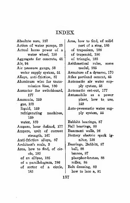
INDEXAbsolute zero, 157
Action of water pumps, 59
Actual horse power of a
water wheel, 110
Aggregate for concrete, 41
Air, 94
Air pressure gauge, 53
water supply system, 51
Alloys, anti-friction, 87
Aluminum wire for trans-
mission line, 180
Ammeter for switchboard,
177
Ammonia, 159' gas, 159
liquid, 159
refrigerating machines,
159
water, 159
Ampere, hour defined, 177
Ampere, unit of current
strength, 167
Anti-friction alloys, 87
Architect's scale, 2
Area, how to find, of cir-
cle, 185
of an ellipse, 185
of a parallelogram, 186
of sector of a circle,
185
Area, how to find, of solid
part of a ring, 185
of trapezium, 186
of trapezoid, 186
of triangle, 185
Arithmetical rules, some
useful, 185
Armature of a dynamo, 170
Atlas Portland cement, 45
Automatic air water sup-
ply system, 55
Automatic cut-out, 177
Automobile as a power
plant, how to use,
152
Auto-pneumatic water sup-
ply system, 55
Babbitt bearings, 87
Ball bearings, 88
Basement walls, 26
Battery electric spark ig-
niter, 138
Bearings, Babbitt, 87
ball, 88
bronze, 87
phosphor-bronze, 88
roller, 88
Belt dressing, 82
how to lace a, 81
187
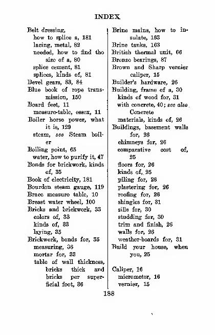
INDEX
Belt dressing,
how to splice a, 181
lacing, metal, 82
needed, how to find the
size of a, 80
splice cement, 81
splices, kinds of, 81
Bevel gears, 83, 84
Blue book of rope trans-
mission, 150
Board feet, 11
measure-table, essex, 11
Boiler horse power, what
it is, 129
steam, see Steam boil-
er
Boiling point, 65
water, how to purify it, 47
Bonds for brickwork, kinds
of, 35
Book of electricity, 181
Bourdon steam gauge, 119
Brace measure table, 10
Breast water wheel, 100
Bricks and brickwork, 33
colors of, 33
kinds of, 33
laying, 35
Brickwork, bonds for, 35
measuring, 36
mortar for, 33
table of waU thickness,
bricks thick and
bricks per super-
ficial foot, 36
Brine mains, how to in-
sulate, 163
Brine tanks, 163
British thermal unit, 66
Bronze bearings, 87
Brown and Sharp vernier
caliper, 15
Builder's hardware, 26
Building, frame of a, 30
kinds of wood for, 31
with concrete, 40; see also.
Concrete
materials, kinds of, 26
Buildings, basement walls
for, 26
chimneys for, 26
comparative cost of,
25
floors for, 26
kinds of,. 25
piling for, 26
plastering for, 26
roofing for, 26
shingles for, 31
siUs for, 30
studding for, 30
trim and finish, 26
walls for, 26
weather-boards for, 31
Build your house, whenyou, 25
Caliper, 16
micrometer, 16
vernier, 15
188
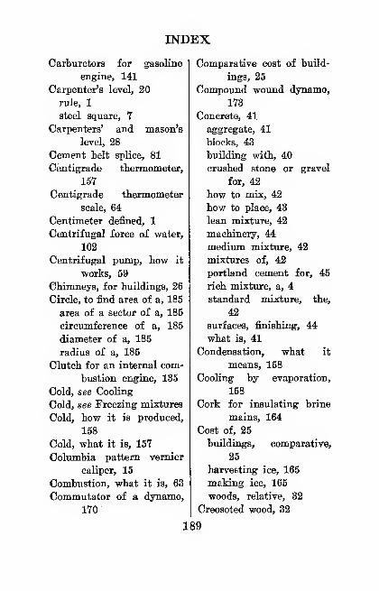
INDEX
Carburetors for gasoline
engine, 141
Carpenter's level, 20
rule, 1
steel square, 7
Carpenters' and mason's
level, 28
Cement belt splice, 81
Centigrade thermometer,
15Y
Centigrade thermometer
scale, 64
Centimeter defined, 1
Centrifugal force of water,
102
Centrifugal pump, how it
works, 59
Chimneys, for buildings, 26
Circle, to find area of a, 185
area of a sector of a, 185
circumference of a, 185
diameter of a, 185
radius of a, 185
Clutch for an internal com-
bustion engine, 135
Cold, see Cooling
Cold, see Freezing mixtures
Cold, how it is produced,
158
Cold, what it is, 15T
Columbia pattern vernier
caliper, 15
Combustion, what it is, 63
Commutator of a dynamo,
lYO'
Comparative cost of build-
ings, 25
Compound wound dynamo,
173
Concrete, 41
aggregate, 41
blocks, 43
building with, 40
crushed stone or gravel
for, 42
how to mix, 42
how to place, 43
lean mixture, 42
machinery, 44
medium mixture, 42
mixtures of, 42
Portland cement for, 45
rich mixture, a, 4
standard mixture, the,
42
surfaces, finishing, 44
what is, 41
Condensation, what it
means, 158
Cooling by evaporation,
158
Cork for insulating brine
mains, 164
Cost of, 25
buildings, comparative,
25
harvesting ice, 165
making ice, 165
woods, relative, 32
Creosoted wood, 32
189
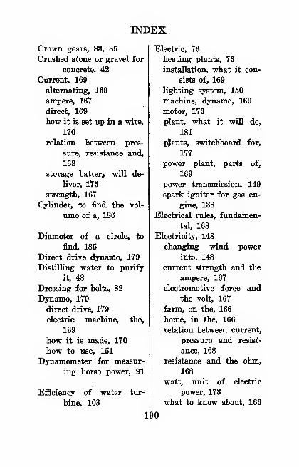
INDEX
Crown gears, 83, 85
Crushed stone or gravel for
concrete, 42
Current, 169
alternating, 169
ampere, 167
direct, 169
how it is set up in a wire,
170
relation between pres-
sure, resistance and,
168
storage battery wiU de-
liver, 175
strength, 167
Cylinder, to find the vol-
ume of a, 186
Diameter of a circle, to
find, 185
Direct drive dynanlo, 179
Distilling water to purify
it, 48
Dressing for belts, 82
Dynamo, 179
direct drive, 179
electric machine, the,
169
how it is made, 170
how to use, 151
Dynamometer for measur-
ing horse power, 91
Efficiency of water tur-
bine, 103
Electric, 73
heating plants, 73
installation, what it con-
sists of, 169
lighting system, 150
machine, dynamo, 169
motor, 173
plant, what it will do,
181
pjants, switchboard for,
177
power plant, parts of.
169
power transmission, 149
spark igniter for gas en-
gine, 138
Electrical rules, fundamen-
tal, 168
Electricity, 148
changing wind power
into, 148
current strength and the
ampere, 167
electromotive force and
the volt, 167
farm, on the, 166
home, in the, 166
relation between current,
pressure and resist-
ance, 168
resistance and the ohm,
168
watt, unit of electric
power, 173
what to know about, 166
190
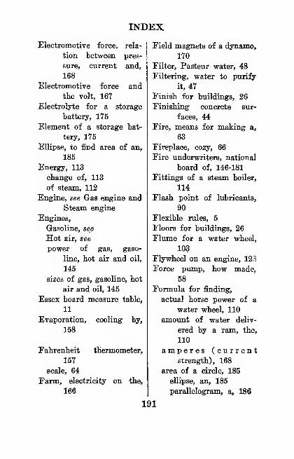
INDEX
Electromotive force, rela-
tion between pres-
sure, current and,
168
Electromotive force and
the volt, 16Y
Electrolyte for a storage
battery, 1Y5
Element of a storage bat-
tery, 175
Ellipse, to find area of an,
185
Energy, 113
change of, 113
of steam, 112
Engine, see Gas engine and
Steam engine
Engines,
Gasoline, see
Hot air, see
power of gas, gaso-
line, hot air and oil,
145
sizes of gas, gasoline, hot
air and oil, 145
Essex board measure table,
11
Evaporation, cooling by,
158
Eahrenheit thermometer,
157
scale, 64
Earm, electricity on the,
166
Eield magnets of a dynamo,
170
Filter, Pasteur water, 48
Filtering, water to purify
it, 47
Finish for buildings, 26
Finishing concrete sur-
faces, 44
Eire, means for making a,
63
Fireplace, cozy, 66
Fire underwriters, national
board of, 146-181
Fittings of a steam boiler,
114
Flash point of lubricants,
90
Flexible rules, 5
Floors for buildings, 26
Flume for a water wheel,
103
Flywheel on an engine, 12S
Force pump, how made,
58
Formula for finding,
actual horse power of a
water wheel, 110
amount of water deliv-
ered by a ram, the,
110
amperes (currentstrength), 168
area of a circle, 185
ellipse, an, 185
parallelogram, a, 186
191

INDEX
Formula for finding,
area of a sector of a
circle, the, 185
solid part of a ring,
185
trapezium, a, 186
trapezoid, a, 186
triangle, a, 185
circumference of a cir-
cle, 185
diameter of a circle,
185
heating surface of a
steam boiler, 130
height of buildings, 98
horse power of
boiler, a, 129
driving a machine, for,
91
electric current, 173
internal combustion
engines, 146
steam engine, a, 130
water wheel, a, 109
ohms (resistance), 168
radius of a circle, 185
belt needed, a, 80
gears, 86
pulley, a, 79
volts (electromotive
force), 168
volume of,
cylinder, a, 186
sphere, a, 186
watts generated, 173
Formula for finding capac-
ity of a water tank,
54
Frame of a building, 30
Framing square, carpen-
ter's, 7
Framing table, rafter, 12
Freezing,
how to prevent water
pipes from, 60
mixtures, 158
point, 65
Friction alloys, anti-, 87
Friction, 87
how to reduce, 87
lubricants to reduce, 89
rolling, 89
sliding, 87
what it does, 87
Friction drive (transmis-
sion), 152
Frost box, how to make a,
60
Frozen, what to do when a
water pipe is, 61
Fuel, 135
hot air engine, for, 135
reservoir for oil engine,
143
Fuels, table average, weights
and volumes of, 184
Fuses, enclosed, 177
Galvanometer, 171
•Gas engine, 135
192
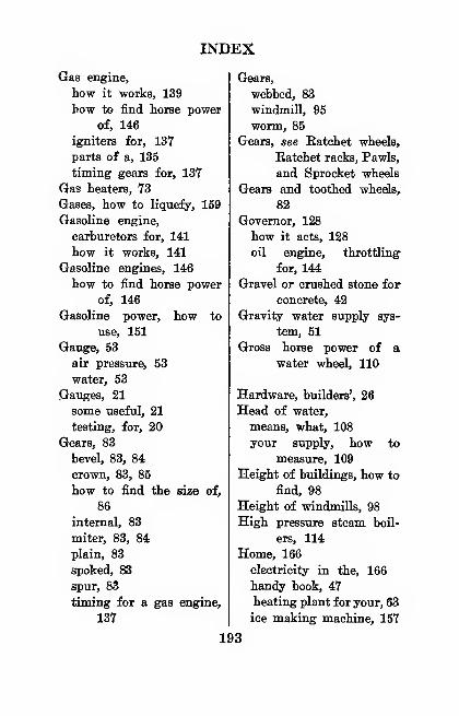
INDEX
Gas engine,
how it works, 139
how to find horse power
of, 146
igniters for, 137
parts of a, 135
timing gears for, 137
Gas heaters, 73
Gases, how to liquefy, 159
Gasoline engine,
carburetors for, 141
how it works, 141
Gasoline engines, 146
how to find horse power
of, 146
Gasoline power, how to
use, 151
Gauge, 53
air pressure, 53
water, 53
Gauges, 21
some useful, 21
testing, for, 20
Gears, 83
bevel, 83, 84
crown, 83, 85
how to find the size of,
86
internal, 83
miter, 83, 84
plain, 83
spoked, 83
spur, 83
timing for a gas engine,
137
Gears,
webbed, 83
windmill, 95
worm, 85
Gears, see Eatchet wheels,
Eatchet racks, Pawls,
and Sprocket wheels
Gears and toothed wheels,
82
Governor, 128
how it acts, 128
oil engine, throttling
for, 144
Gravel or crushed stone for
concrete, 42
Gravity water supply sys-
tem, 51
Gross horse power of awater wheel, 110
Hardware, builders', 26
Head of water,
means, what, 108
your supply, how to
measure, 109
Height of buildings, how to
find, 98
Height of windmills, 98
High pressure steam boil-
ers, 114
Home, 166
electricity in the, 166
handy book, 47
heating plant for your, 63
ice making machine, 157
193
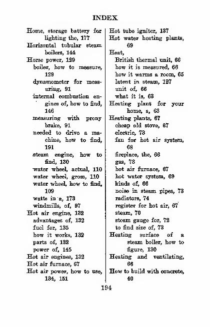
INDEX
Home, storage battery iox
lighting the, 177
Horizontal tubular steam.
boilers, 144
Horse power, 129
boiler, how to measure,
129
dynamometer for meas-
uring, 91
internal combustion en-
gines of, how to find,
146
measuring with prony
brake, 91
needed to drive a ma-chine, how to find,
191
steam engine, how to
find, 130
-water wheel, actual, 110
water wheel, gross, 110
water wheel, how to find,
109
watts in a, 173
windmills, of, 97
Hot air engine, 132
advantages of, 132
fuel for, 135
how it works, 132
parts of, 132
power of, 145
Hot air engines, 132
Hot air furnace, 67
Hot air power, how to use,
134, 151
Hot tube igniter, 137
Hot water heating plants,
69
Heat,
British thermal unit, 66
how it is measured, 66
how it warms a room, 65
latent in steam, 127
unit of, 66
what it is, 63
Heating plant for your
home, a, 63
Heating plants, 67
cheap old stove, 67
electric, 73
fan for hot air system,
68
fireplace, the, 66
gas, 73
hot air furnace, 67
hot water system, 69
kinds of, 66
noise in steam pipes, 73
radiators, 74
register for hot air, 67
steam, 70
steam gauge for, 72
to find size of, 73
Heating surface of a
steam boiler, how to
figure, 130
Heating and ventilating,
66
How to build with concrete,
40
194
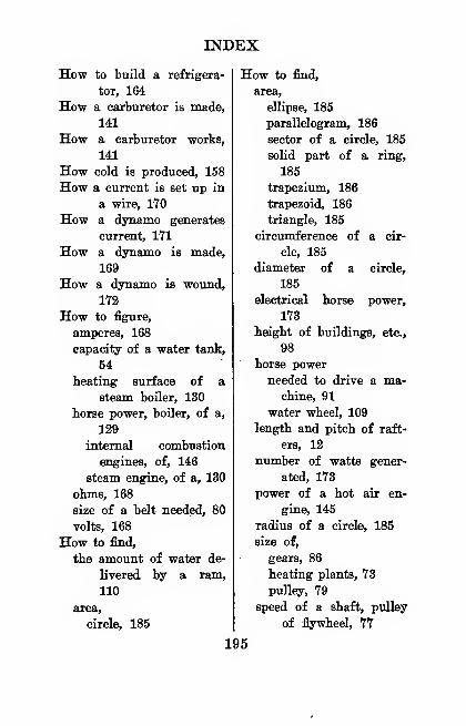
INDEX
How to build a refrigera-
tor, 164
How a carburetor is made,
141
How a carburetor works,
141
How cold is produced, 158
How a current is set up in
a wire, lYO
How a dynamo generates
current, 171
How a dynamo is made,
169
How a dynamo is wound,
172
How to figure,
amperes, 168
capacity of a water tank,
54
heating surface of a
steam boiler, 130
horse power, boiler, of a,
129
internal combustion
engines, of, 146
steam engine, of a, 130
ohms, 168
size of a belt needed, 80
volts, 168
How to find,
the amount of water de-
livered by a ram,
110
area,
circle, 185
How to find,
area,
ellipse, 185
parallelogram, 186
sector of a circle, 185
solid part of a ring,
186
trapezium, 186
trapezoid, 186
triangle, 185
circumference of a cir-
cle, 185
diameter of a circle,
185
electrical horse power,
173
height of buildings, etc.,
98
horse power
needed to drive a ma-chine, 91
water wheel, 109
length and pitch of raft-
ers, 12
number of watts gener-
ated, 173
power of a hot air en-
gine, 145
radius of a circle, 185
size of,
gears, 86
heating plants, 73
pulley, 79
speed of a shaft, pulley
of flywheel, 77
195
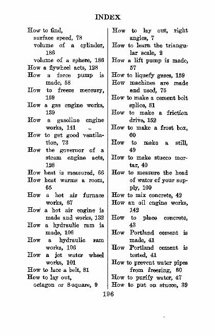
INDEX
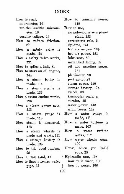
INDEX
How to read,
micrometer, 16
ten-thousandths microm-
eter, 19
vernier caliper, 15
How to reduce friction,
87
How a safety valve is
made, 121
How a safety valve works,
121
How to splice a belt, 81
How to start an oil engine,
144
How a steam boiler is
made, 114
How a steam engine is
made, 122
How a steam engine works,
126
How a steam gauge acts,
113
How a steam gauge is
made, 119
How steam is measured,
113
How a steam whistle is
made and works, 121
How a storage battery is
made, 125
How to tell good lumber,
28
How to test sand, 41
How to thaw a frozen water
pipe, 61
How to transmit power,
149
How to use,
an automobile as a power
plant, 152
carpenter's rule, 2
dynamo, 151
hot air engine, 134
hot air power, 151
lubricants, 89
metal belt lacing, 82
oil and gasoline power,
151
planimeter, 23
protractor, 23
steam power, 150
storage battery, 1Y5
stucco, 38
triangular scale, 4
vernier, 15
water power, 149
wind power, 148
How a water gauge is
made, IIY
How a water turbine is
made, 103
How a water turbine
works, 102
How water wheels work,
100
House, when you build
your, 25
Hydraulic ram, 105
how it is made, 106
how it works, 106
197
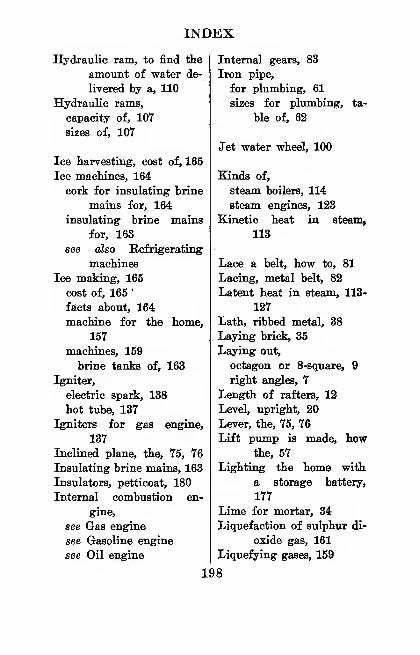
INDEX
Hydraulic ram, to find the
amount of water de-
livered by a, 110
Hydraulic rams,
capacity of, 107
sizes of, 107
Ice harvesting, cost of, 165
Ice machines, 164
cork for insulating brine
mains for, 164
insulating brine mains
for, 163
see also Refrigerating
machines
Ice making, 165
cost of, 165'
facts about, 164
machine for the home,
157
machines, 159
brine tanks of, 163
Igniter,
electric spark, 138
hot tube, 137
Igniters for gas engine,
137
Inclined plane, the, 75, 76
Insulating brine mains, 163
Insulators, petticoat, 180
Internal combustion en-
gine,
see Gas engine
see Gasoline engine
see Oil engine
Internal gears, 83
Iron pipe,
for plumbing, 61
sizes for plumbing, ta-
ble of, 62
Jet water wheel, 100
Kinds of,
steam boilers, 114
steam engines, 123
Kinetic heat in steam,
113
Lace a belt, how to, 81
Lacing, metal belt, 82
Latent heat in steam, 113-
127
Lath, ribbed metal, 38
Laying brick, 35
Laying out,
octagon or 8-8quare, 9
right angles, 7
Length of rafters, 12
Level, upright, 20
Lever, the, 75, 76
Lift pump is made, howthe, 57
Lighting the home with
a storage battery,
177
Lime for mortar, 34
Liquefaction of sulphur di-
oxide gas, 161
Liquefying gases, 159
198
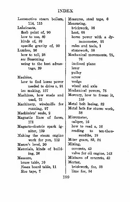
INDEX
Locomotive steam boilers,
114, 115
Lubricants,
flash point of, 90
how to use, 89
kinds of, 89
specific gravity of, 90
Lumber, 26
how to tell, 28
see Seasoning
using to the best advan-
tage, 29
Machine,
how to find horse power
needed to drive a, 91
ice making, 157
Machines, how made and
used, 75
Machinery, windmills for
running, 97
Machinists' scale, 2
Magnetic lines of force,
171
Magneto-electric spark ig-
niter, 139
Making the steam engine
work for you, 112
Mason's level, 20
Materials, kinds of build-
ing, 26
Measure,
brace table, 10
Essex board table, 11
Eoe tape, 7
Measures, steel tape, 6
Measuring,
brickwork, 36
heat, 66
horse power with a dy-
namometer, 91
rules and tools, 1
stonework, 38
Mechanical movements, 75,
76
inclined plane
lever
pulley
screw
wedge
wheel and axle
Mechanical powers, 75
Mercury, how to freeze it,
159
Metal belt lacing, 82
Metal lath for stucco work,
38
Micrometer,
caliper, 16
how to read a, 16
reading to ten-thou-
sandths, 19
Miter gears, 83, 84
Mixing,
concrete, 42
valve for oil engine, 143
Mixtures of concrete, 42
Mortar,
brickwork, for, 33
lime for, 34
199
INDEX
Mortar,
sand for, 34
stonework, for, 37
Motor car, how to use as a
power plant, 152
National Board of Fire Un-derwriters, 146-181
National electric code, 181
Needle nozzle for water
wheel, 101
Octagon or 8-square, lay-
ing out an, 9
Ohm, unit of resistance,
168
Oil engine,
economy of operation,
145
fuel reservoir for, 143
how to start an, 144
mixing valve for, 143
throttling governor for,
144
Oil engines,
how to find horse power
of, 145
how they work, 142
Oil power, how to use, 151
Overshot water wheel, 100
Packing for stuffing box-
es, 129
Parallelogram, to find area
of, 186
Pasteur water filter, 48
Pattern maker's shrinkage
rule, 5
Pelton water wheel, 101
Penstock for water wheel,
103
Phosphor-hronze bearing
metal, 88
Piling for buildings, 26
Pipes from freezing, how to
prevent water, 60
Pitch of rafters, 12
Pitches, table of common,13
Placing concrete, 43
Plain gears, 83
Planimeter, the, 23
Plaster for walls, 34
Plastering for. buildings, 26
Plumb, the, 20
Plumb glass, 20
Plumbing,
a word on, 61
iron pii)e for, 61
red lead for joints, 61
table of iron pipe sizes
for, 62
Pneumatic water supply
system, 51
Portland cement.
Atlas, 45
concrete, for, 45
made, is how, 41
stucco, for, 38
tested, is how, 41
200
INDEX
Potential, or latent heat in Pulleys, split, 154
steam, 113
Poweir,
how to use hot air, 151
how to use' wind, 148
source of all useful, 94
water, 99
wind, 94
Power of engines, 145
gas
gasoline
hot air
oil
Power of a hot air eng^ine,
146
Power plant,
how to use an automo-
bile as a, 152
parts of an electric, 169
steam, the, 112
Power plants compared,
cost of operation of,
112
Power transmission, fric-
tion drive, 152
Preserve wood, how to,
32
Prevent water pipes from
freezing, how to, 60
Prony brake for meas\ir-
ing horse power, 91
Protractor, the, 20
Pulley, the, 76
how to find the size of,
79
Pump,action of,
centrifugal, 60
force, 58
lift pumps, 59
automatic air or auto-
pneumatic, 56
is made,
how a centrifugal, 59
how a lift, 57
how the force, 58
Pumps, kinds of water,
58
Pumps and pumping, 57
Padiators for heating
plants, 70, 72, 74
Padius of a circle, to find,
185
Kafter framing table, 12
Eafters,
buildings, for, 30
length, rise and pitch of,
12
Bam, see Hydraulic ramPatchet,
racks and pinions, 85
wheels, 85
Bating of storage batter-
ies, 177
Befrigerators, kinds of,
159
Befrigerating machines,
ammonia, 159
201
INDEX
Refrigerating machines,
sulphur dioxide, 160
see also Ice machines
Kefrigerator, how to huild
a, 164
Registers foi hot air heat-
ing plants, 67
Relation between current,
pressure and resist-
ance, 168
Resistance,
box, 168
ohm, and the, 168
relation between pres-
sure, current and,
168
Right angles, how to lay
out, 7
Ring, to find the area of
solid part of a ring,
185
Rise of rafters, 112
Roe tape measure, 7
Roller bearings, 88
Rolling friction, 87
Roofing materials, 26
Rope,
drive transmission, 149
transmission, blue book
of, 150
Rule,
carpenter's boxwood, 1
pattern makers' shrink-
age, 3
triangular boxwood, 2
Rules,
electric wiring, for, 181
flexible, 3
installing and using in-
ternal combustion
engines, for, 146
measuring, for, 1
useful arithmetical, 185
Rules and tables, useful, 183
Sand,
how to test, 41
mortar, for, 34
Safety valve, how it is
made and works, 121
Scale,
architects' and machin-
ists', 2
how to learn the trian-
gular, 2
how to use the triangu-
lar, 4
Scales compared, thermom-
eter, 64
Scotch glass for tubes for
water gauge, 117
Screw, the, 76
Seasoning,
hot air, 28
natural, 28
wood, 27
Sensible heat in steam,
113
Septic tank sewage system,
62
202
INDEX
Sewage,
septic tank system, 62
word on, a, 61
Shingle nails, table of, 184
Shingles,
roofs, for, 31
table of number andweight, 183
Shrinkage rule, pattern
makers', 5
Sills for buildings, 30
Sizes of,
engines, 145
gas
gasoline
hot air
oil
steam boilers, 122
Sliding friction, 87
Speed,
indicator, 77-131
shaft, pulley or flywheel,
how to find the, 77
surface or peripheral, 78
Specific gravity of lubri-
cants, 90
Sphere, to find the volume
of a, 186
Splice a belt, how to, 81
Splice, cement belt, 81
Split pulleys, 154
Spoked gears, 83
Sprocket wheels, 85
Spur gears, 83
Square, carpenter's steel, 7
Starrett vernier caliper, 15
Steam, energy of, 112
great prime power, 112
how it is measuied, 113
kinetic, or sensible, heat
in, 113
latent heat in, 127
pipes, noise in, 73
potential or latent heat
in, 113
whistle, 121
Steam boiler,
fittings of a, 114
globe valve
safety valve
steam delivery pipe
steam gauge
steam gauge cocks
steam whistle
water gauge
water pumpheating surface of, 130
how to find heating sur-
face of a, 130
how to find the horse
power of a, 129
how it is made, 114
return tubular, 114-115
safety valve for, 121
water for gauge, 116
water intake pipe for,
116
what boiler horse powei
is, 129
whistle for, 121
203
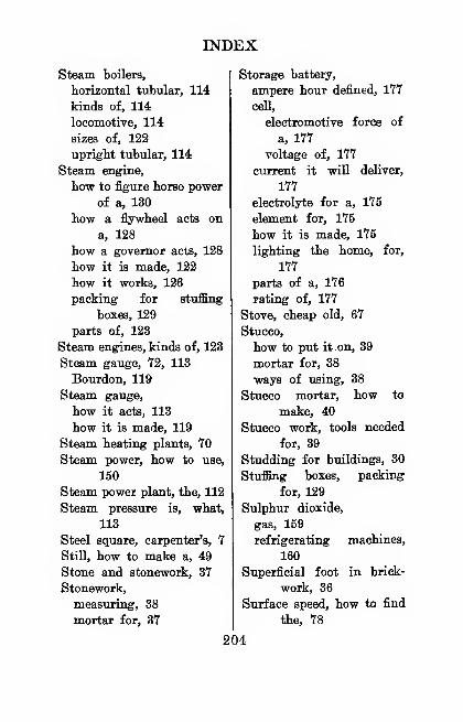
INDEX
Steam boilers,
horizontal tubular, 114
kinds of, 114
locomotive, 114
sizes of, 122
upright tubular, 114
Steam engine,
how to figure horse power
of a, 130
how a flywheel acts on
a, 128
how a governor acts, 128
how it is made, 122
how it works, 126
packing for stuffing
boxes, 129
parts of, 123
Steam engines, kinds of, 123
Steam gauge, 72, 113
Bourdon, 119
Steam gauge,
how it acts, 113
how it is made, 119
Steam heating plants, 70
Steam power, how to use,
150
Steam power plant, the, 112
Steam pressure is, what,
113
Steel square, carpenter's, 7
Still, how to make a, 49
Stone and stonework, 37
Stonework,
measuring, 38
mortar for, 37
Storage battery,
ampere hour defined, 177
cell,
electromotive force of
a, 177
voltage of, 177
current it will deliver,
177
electrolyte for a, 175
element for, 175
how it is made, 175
lighting the home, for,
177
parts of a, 176
rating of, 177
Stove, cheap old, 67
Stucco,
how to put it on, 39
mortar for, 88
ways of using, 38
Stucco mortar, how to
make, 40
Stucco work, tools needed
for, 39
Studding for buildings, 30
Stuffing boxes, packing
for, 129
Sulphur dioxide,
gas, 159
refrigerating machines,
160
Superficial foot in brick-
work, 36
Surface speed, how to find
the, 78
204
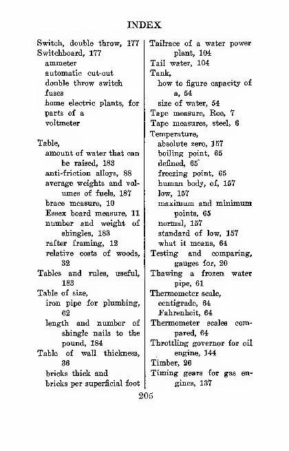
INDEX
Switch, double throw, 177
Switchboard, 177
ammeter
automatic cut-out
double throw switch
fuses
home electric plants, for
parts of a
voltmeter
Table,
amount of water that can
be raised, 183
anti-friction alloys, 88
average weights and vol-
umes of fuels, 187
brace measure, 10
Essex board measure, 11
number and weight of
shingles, 183
rafter framing, 12
relative costs of woods,
32
Tables and rules, useful,
183
Table of size,
iron pipe for plumbing,
62
length and number of
shingle nails to the
pound, 184
Table of wall thickness,
36
bricks thick and
bricks per superficial foot
Tailrace of a water power
plant, 104
Tail water, 104
Tank,
how to figure capacity of
a, 54
size of water, 54
Tape measure. Roe, 7
Tape measures, steel, 6
Temperature,
absolute zero, 157
boiling point, 65
defined, 65
freezing point, 65
human body, of, 157
low, 157
maximum and minimumpoints, 65
normal, 157
standard of low, 157
what it means, 64
Testing and comparing,
gauges for, 20
Thawing a frozen water
pipe, 61
Thermometer scale,
centigrade, 64
Fahrenheit, 64
Thermometer scales com-
pared, 64
Throttling governor for oil
engine, 144
Timber, 26
Timing gears for gas en-
gines, 137
205
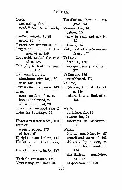
INDEX
Tools,
measuring, for, 1
needed for stucco work,
39
Toothed wheels, 82-85
gears, 82
Towers for windmills, 99
Trapezium, to find the
area of a, 186
Trapezoid, to find the area
of a, 186
Triangle, to find the area
of a, 185
Transmission line,
aluminum wire for, 180
wire for, 179
Transmission of power, 149
Tree,
cross section of a, 27
how it is formed, 27
when it is feUed, 26
Triangiilar boxwood rule, 2
Trim for buildings, 26
TJndeirshot water wheel, 100
Unit of,
electric power, 173
of heat, 66
Upright steam boilers, 114
Useful arithmetical rules,
185
Useful rules and tables, 183
Variable resistance, 177
Ventilating and heat, 66
Ventilation, how to get
good, 73
Vernier, the, 14
caliper, 15
how to read and use it,
15
Pierre, 14
Volt, unit of electromotive
force, 167
Voltage,
drop in, 180
storage battery and cell,
177
Voltmeter, 168
switchboard, 177
Volume,
cylinder, to find the, of
a, 186
sphere, how to find, ,of a,
186
WaUs,
buildings, for, 26
plaster for, 34
thickness in brickwork,
36
Water,
boiling, purifying, by, 47
centrifugal force of, 102
delivered by a ram, to
find the amount of,
110
distillation, purifying,
by, 148
evaporation of, 129
206
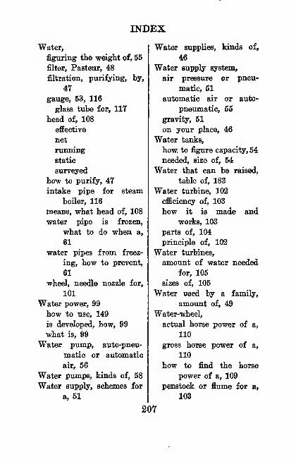
INDEX
Water,
figuring the weight of, 55
filter, Pasteur, 48
filtration, purifying, by,
47
gauge, 53, 116
glass tube for, 117
head of, 108
effective
net
running
static
surveyed
how to purify, 47
intake pipe for steam
boiler, 116
means, what head of, 108
water pipe is frozen,
what to do when a,
61
water pipes from freez-
ing, how to prevent,
61
wheel, needle nozzle for,
101
Watei power, 99
how to use, 149
is developed, how, 99
what is, 99
Water pump, auto-pneu-
matic or automatic
air, 56
Water pumps, kinds of, 58
Water supply, schemes for
a, 51
Water supplies, kinds of,
46
Water supply system,
air pressure or pneu-
matic, 51
automatic air or auto-
pneiunatic, 55
gravity, 51
on your place, 46
Water tanks,
how, to figure capacity, 54
needed, size of, 54
Water that can be raised,
table of, 183
Water turbine, 102
efficiency of, 103
how it is made and
works, 103
parts of, 104
principle of, 102
Water turbines,
amount of water needed
for, 105
sizes of, 105
Water used by a family,
amount of, 49
Water-wheel,
actual horse power of a,
110
gross horse power of a,
110
how to find the horse
power of a, 109
penstock or flume for a,
103
207
INDEX
Water wlieelB, 100, 101
breast
jet
kinds of, 99
overshot
Pelton
turbine
undershot
Water of your supply, howto measure head of,
109
Watt, unit of electric
power, 173
Watts,
generated, how to figure,
173
horse power, in a, 173
Weatherboards for build-
ings, 31
Webbed gears, 83
Wedge, the, 76
Weight of water, figuring
the, 55
Wheels,
ratchet, 85
sprocket, 85
toothed, 82
Whistle, steam, 121
Wind, the, 94
Windmill, parts of a, 95
Windmills,
height of, 98
horse power of, 97
machinery for, sizes of,
97
Windmills,
pumping, sizes of, 97
towers for, 99
Windpower,
developed, how, 94
electricity, changing
into, 148
how to use, 148
Wind power, 94
what is, 94
Wind power to work, put-
ting, 94
Winds, height of, 98
Wiring, electric apparatus
in parallel, -181
inside and outside, 180
Wire,
rubber covered, 180
transmission line, for, 179
weather-proof, 180
Wood,building, kinds of, 31
how to preserve, 33
inside work, for, 32
outside work, for, 32
seasoning, 27
Woods,
kinds to use, 32
pounds per foot, 32
relative costs of, 32
where to use certain
kinds of, 31
Worm gears, 85
Zero, absolute, 157
208(3)


:!| ' i
i'Vi'iiffS: :' ;'iH i,


