
Motor Management SystemTeSys T
CatalogueOctober
07

Simplicity
Cost effective“optimum” offers thatmake selection easyfor most typicalapplications
Products that areeasy to understandfor users, electriciansand automationspecialists
User-friendly intuitiveprogramming
Ingenuity
Auto-adapts to itsenvironment, “plug &play”
Application functions,control,communication anddiagnosticsembedded in theproducts
User-friendly operationeither directly on theproduct or remotely
Flexibility
Interchangeablemodular functions, tobetter meet therequirements forextensions
Software andaccessories arecommon to multipleproduct families
Openness
Compliant with fieldbus, connection andsoftware standards
Enablingdecentralised orremote surveillancevia the web withTransparent Readyproducts
Compactness
High functionality in aminimum of space
Freedom inimplementation
We leverage ingenuity and intelligence tomake our products easy to use.
Simply Smart!
1
Contents
Motor Management SystemTeSys T
TeSys T controllers and extension modules
“Protection components” selection guide . . . . . . . . . . . . . . . . . pages 2 and 3
General: motor and machine protection . . . . . . . . . . . . . . . . . . . . . pages 4 to 9
“TeSys T” selection guide . . . . . . . . . . . . . . . . . . . . . . . . . . . . . pages 10 and 11
Functions . . . . . . . . . . . . . . . . . . . . . . . . . . . . . . . . . . . . . . . . . . pages 12 and 15
Presentation, description . . . . . . . . . . . . . . . . . . . . . . . . . . . . . . pages 16 and 17
Programming . . . . . . . . . . . . . . . . . . . . . . . . . . . . . . . . . . . . . . . pages 18 and 19
Characteristics . . . . . . . . . . . . . . . . . . . . . . . . . . . . . . . . . . . . . . . pages 20 to 22
Tripping curves . . . . . . . . . . . . . . . . . . . . . . . . . . . . . . . . . . . . . . . . . . . . page 23
References . . . . . . . . . . . . . . . . . . . . . . . . . . . . . . . . . . . . . . . . . . pages 24 to 27
Dimensions, mounting . . . . . . . . . . . . . . . . . . . . . . . . . . . . . . . . pages 28 and 29
Schemes . . . . . . . . . . . . . . . . . . . . . . . . . . . . . . . . . . . . . . . . . . . . pages 30 to 33
Combinations . . . . . . . . . . . . . . . . . . . . . . . . . . . . . . . . . . . . . . . . . . . . . page 34
Substitution table . . . . . . . . . . . . . . . . . . . . . . . . . . . . . . . . . . . . . . . . . . page 34

Selection guide 6 Protection components 6
Protection relays and controllers
Applications Motor protection
Thermal motor protection
Protection - Motor overload- Stalling- Phase failure
Communication –
Used with contactor type LC1 K, LP1 K LC1 D LC1 F
Motor current (In) 0.11…16 A 0.1…150 A 30…630 A
Relay type LR2 K LR D LR9 F
Pages Please consult our catalogue “Power Control and Protection, the essential guide”.
2
66
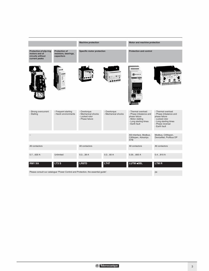
Machine protection Motor and machine protection
Protection of slip ring motors and of circuits without current peaks
Protection of resistors, bearings, capacitors
Specific motor protection Protection and control
- Strong overcurrent- Stalling
- Frequent starting- Harsh environments
- Overtorque- Mechanical shocks- Locked rotor- Phase failure
- Overtorque- Mechanical shocks
- Thermal overload- Phase imbalance and phase failure- Motor stalling- Long starting times- Earth fault
- Thermal overload- Phase imbalance and phase failure- Locked rotor - Long starting times- Phase reversal- Earth fault
– AS-Interface, Modbus, CANopen, Advantys STB
Modbus, CANopen, DeviceNet, Profibus DP
All contactors All contactors All contactors All contactors
0.7…630 A Unlimited 0.3…38 A 0.3…60 A 0.35…800 A 0.4…810 A
RM1 XA LT3 S LR97D LT47 LUTM 0BL LTM R
Please consult our catalogue “Power Control and Protection, the essential guide”. 24
3

Protection components 0
Motor and machine protection
IntroductionExceeding the operating limits of an electric motor will lead, eventually, not only to
destruction of the motor itself but also of the mechanisms it drives.
This type of load can be the cause of electrical or mechanical faults.
b Electrical faults:
v overvoltage, voltage drop, imbalance and phase failure which cause variations in
the current drawn,
v short-circuits which can cause the current to reach levels capable of destroying
the load.
b Mechanical faults:
v locked rotor,
v brief or prolonged overload which leads to an increase in the current drawn by the
motor, and therefore overheating.
The cost of these faults must take into account loss of production, loss of raw
materials, repair of the production tool, poor quality of production and delays in
delivery.
These faults can also have dramatic consequences on the safety of persons in
direct or indirect contact with the motor.
To prevent these faults, protection measures are necessary.
They make it possible to isolate the equipment to be protected from the mains
supply, by measuring electrical values (voltage, current, etc…).
Each motor starter must therefore have:
b short-circuit protection, to detect and break, as quickly as possible, abnormal
currents generally greater than 10 times the rated current (In).
b overload protection, to detect increases in current up to about 10 In and switch
off the starter before overheating of the motor and conductors damages the
insulation.
This protection is provided by specific devices such as fuses, circuit-breakers and
thermal overload relays, or by more integrated devices offering several types of
protection.
General
4

Protection components 0
Motor and machine protection
Causes, effects and consequences of various faultsThere are two types of fault:
b Internal faults within the motor.
b External faults: these are located outside the electric motor but their
consequences can lead to damage inside the motor.
Faults Cause Effects Consequences on the motor and on the machine
Short-circuit Contact between several phases, or
between one phase and neutral or
between several turns of the same
phase.
b Current peak
b Electrodynamic forces on the
conductors
Destruction of windings
Overvoltage b Lightning
b Electrostatic discharge
b Operation
Dielectric breakdown in the windings Destruction of the windings due to loss
of insulation
Phase imbalance and phase failure
b Opening of a phase
b Single-phase load upstream of the
motor
b Short-circuit between the turns of
the same winding
b Reduction of usable torque, effi ciency
and speed
b Increase in losses
b Starting impossible if phase failure
Overheating (1)
High starting frequency
b Failure of the automation system
b Too many manual control
operations
b Numerous fault trips
High stator and rotor temperature rise
due to the frequent start current
Overheating (1)
Consequences on the process
Voltage variations
b Instability of the mains voltage
b Connection of heavy loads
b Reduction of usable torque
b Increase in losses
Overheating (1)
Harmonics Pollution of the mains supply by
variable speed drives, inverters, etc...
b Reduction of usable torque
b Increase in losses
Overheating (1)
Long starting time
b Resistive torque too high (load too
heavy)
b Voltage drop
Increase in starting time Overheating (1)
Jamming b Mechanical problem (crusher)
b Seizures
Overcurrent Overheating (1)
Consequences on the process
No-load running
b Pump running empty
b Mechanical break in drive to the
load
Drop in current drawn Consequences on the process
Frequency fl uctuations
b Overload of a supply powered by
limited independent sources
b Faulty alternator speed regulator
b Increase in losses
b Interferes with synchronous devices
(clock, recorder, ...)
–
Overload b Increase in resistive torque
b Voltage drop
b Drop in power factor
Increase in current consumption Overheating (1)
Loss of machine excitation
b Significant drop in excitation
current
b Break in rotor winding
b Increase in active power
b Drop in power factor
Significant overheating of rotor and cage
Phase-Earth fault
b Accidental Phase-Earth contacts
b Accidental Phase-machine casing
contacts (casing connected to earth)
b Overvoltage developed in the mains
supply
b Rise in earth potential (safety of
persons)
Consequences on safety of persons
(1) Then, in the longer term, depending on the seriousness of the fault and/or its frequency, short-circuit and destruction of the windings.
General (continued)
5

Protection components 0
Motor and machine protection
Protection functions Short-circuit protectionGeneral
A short-circuit results in a very rapid rise in current which can reach several hundred
times the value of the operational current.
The consequences of a short-circuit are dangerous to both equipment and persons.
It is therefore imperative to use protection devices to detect the fault and very
quickly break the circuit.
Two types of protection are commonly used:
b fuses which break the circuit by melting, which then requires their replacement,
b magnetic trip circuit-breakers, often more simply called “magnetic circuit-
breakers”, which only require re-setting to put them back into service.
Short-circuit protection can also be built-into multifunction devices such as motor
circuit-breakers and contactor-breakers.
The main characteristics of short-circuit protection devices are:
b Their breaking capacity: this is the highest prospective short-circuit current value
that a protection device can break at a given voltage.
b Their making capacity: this is the highest current value that the protection device
can make at its rated voltage in specified conditions. The making capacity is equal
to k times the breaking capacity.
Fuses Fuses provide individual phase protection (single-pole), with a high breaking
capacity in a compact size:
b mounted either in fuse carriers,
b or in isolators, replacing the original links or shunt bars.
For motor protection, time delay fuses are used. Their design characteristics allow
them to conduct the high magnetising currents that occur when motors are
switched on. They are therefore unsuitable for overload protection. This is why an
overload relay must be included in the motor power supply circuit.
Magnetic circuit-breakers These circuit-breakers protect installations against short-circuits, within the limit of
their breaking capacity.
Magnetic circuit-breakers provide omnipole breaking as standard.
For relatively low short-circuit currents, the operation of a circuit-breaker is faster
than that of fuses.
The thermal and electrodymanic effects are also limited, therefore ensuring better
protection of cables and equipment.
566997
566998
LS1 D32 fuse carrier GS1 switch-disconnector-fuses
TeSys U LUB 12 starter with LUCApp control unit
510586
General (continued)
56
69
99
GV2 PType E self protected starter
6

Protection components 0
Motor and machine protection
Protection functions (continued) Overload protectionGeneral
An overload condition is the most frequently encountered fault. The symptoms are a
rise in the current drawn by the motor and thermal effects. A rapid return to normal
operating conditions is important.
The actual operating conditions (ambient temperature, operating altitude and type
of standard duty) are essential to determine the operating values of the motor
(power, current) and to be able to select effective overload protection. These
operational values are given by the motor manufacturer.
According to the level required, protection can be provided by:
b overload relays and thermal overload relays (bi-metallic or electronic type) which
protect motors in the event of:
v overload, by monitoring the current drawn by each phase,
v phase imbalance or failure, by their differential mechanism.
b relays with PTC thermistor probes (Positive Temperature Coeffi cient),
b overtorque relays,
b multifunction relays.
Overload relaysThese relays protect motors against overload. They must allow the temporary
overload that occurs on starting and must only trip if the starting time is abnormally
long.
The overload relay will be selected according to the length of the starting time
(tripping class) and the motor rating.
These relays have a thermal memory (except for certain electronic overload relays,
indicated by their manufacturers) and can be connected:
b either in series with the load,
b or to current transformers placed in series with the load.
Bi-metallic thermal overload relaysCombined with a contactor, these relays protect the line and the equipment against
small and prolonged overloads. They must be protected against strong overcurrent
by a circuit-breaker or fuses.
These relays may be used on an a.c. or d.c. system and are generally:
b 3-pole,
b compensated, i.e. insensitive to ambient temperature variations,
b with manual or automatic reset,
b graduated with a “motor FLC” scale: allowing direct setting to the full load current
as shown on the motor rating plate.
They can also be sensitive to phase failure: this is known as ‘differential’.
This type of relay is extremely reliable and is a relatively low cost device.
Electronic thermal overload relays Electronic thermal overload relays have the advantage of electronics which allow a
more complex thermal image of the motor to be created.
They can be combined with products having complementary functions, such as:
b temperature sensing via PTC probes,
b protection against jamming and overtorque,
b protection against phase reversal,
b earth fault protection,
b protection against no-load running,
b alarm function.
567000
LRD 02thermal overload relay
510587
567002
RM4 JA current measurement relay
TeSys U starter with “thermal overload alarm” function module
General (continued)
7

Protection components 0
Motor and machine protection
Protection functions (continued) Overload protection (continued)Relays for use with PTC thermistor probes
With direct sensing of the stator windings, these relays can be used to protect
motors against:
b overload,
b a rise in ambient temperature,
b a ventilation circuit fault,
b a high starting frequency,
b mechanical shocks, etc...
Overload (or overtorque) relaysThese relays protect the drive line in the event of a locked rotor, seizure or
mechanical shocks. This is an additional protection.
Unlike thermal overload relays, these relays do not have a thermal memory. They
have definite time characteristics (adjustable current threshold and time delay).
The overtorque relay can be used as overload protection for motors with long
starting times or very frequent starting (for example, lifting hoists).
Multifunction relaysOvercurrent relays are limited when it is necessary to take into account problems
associated with voltage, temperature or special applications.
New production or maintenance management needs have prompted manufacturers
to offer products which provide not only adaptable protection, but also complete
management of the motor and its load.
They incorporate:
b current and voltage sensors (TeSys T controllers),
b hybrid analog and digital electronic technology,
b the use of communication buses for data exchange and control,
b powerful motor modelling algorithms,
b integrated application programs whose parameters can be set.
These products make it possible to reduce installation and operating costs by
reducing maintenance and downtime.
TeSys U starters:The multifunction relay is incorporated in the motor starter.
This solution is very compact with reduced wiring. It is limited to 32 A.
TeSys U controllers: The multifunction relay is separate from the power line and reuses the function
blocks from the TeSys U solution. It can be used in conjunction with a contactor up
to 810 A.
TeSys T controllers: The multifunction relay is separate from the power line and incorporates inputs and
outputs. It can be used in conjunction with a contactor up to 810 A.
567003
LT3 S relays for use with thermistor probes
567004
LR97 D07 instantaneous electronic overcurrent relays
510588
TeSys U LUB 32 starter with multifunction control unitLUC M
567006
TeSys U controllerLUTM 20BL
567007
TeSys T controllerLTM R08MBD
General (continued)
8

Protection components 0
Motor and machine protection
Protection relay selection table Motor protection Machine
protection
Motor and machine
protection
Relay type Thermal
overload
relays
LR2 K,
LRD, LR9 F,
LR9 D (1)
Relays for
use with
PTC probes
LT3
Overtorque
relays
LR97 D,
LT47
TeSys U
controller
LUT M
TeSys T
controller
LTM R
Causes of overheating (2) (2) (2) (3)Slight overload
Locked rotor
No-load running
Supply phase failure LR9 7D
Ventilation fault With probes
Abnormal
temperature rise
With probes
Shaft bearing seizure With probes
Insulation fault
Protracted starting time
Severe duty With probes
Voltage variation
Frequency fl uctuations
Loss of
machine excitation
Ideally suited
Possible solution
Not suitable (no protection)
(1) Similar protection included in GV2 & GV3 starters.(2) Protection based on current.(3) Protection based on current and voltage.
General (continued)
9

Selection guide 1 Protection componentsTeSys T Motor Management System
Application Multifunction motor and machine protection
Device type Controllers
For network/bus Modbus CANopen
Current range 0.4…100 A (with internal current transformer)100…810 A (with external current transformer)
Control voltage 24 V100…240 V
Number of I/O 6 inputs4 outputs
Measurements - Current between phases- Earth fault- Motor temperature
Protection and monitoring functions - Thermal overload- Motor temperature monitoring- Phase imbalance and phase failure- Locked rotor- Long starting times- Phase reversal- Earth fault
Type reference LTM R M LTM R C
Pages 24
10
1
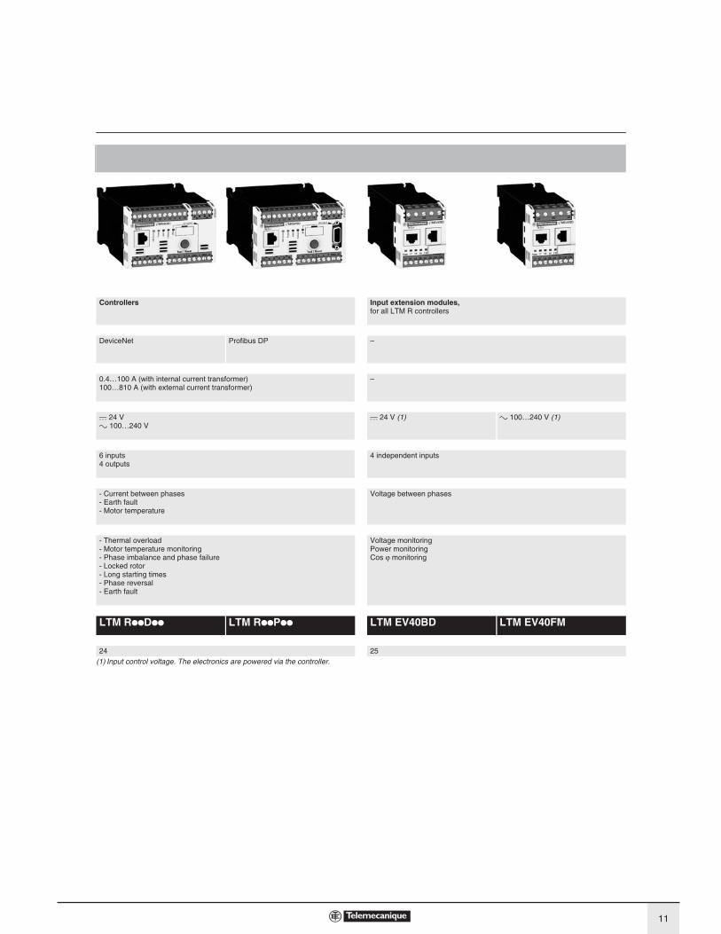
1
Controllers Input extension modules,for all LTM R controllers
DeviceNet Profibus DP –
0.4…100 A (with internal current transformer)100…810 A (with external current transformer)
–
24 V100…240 V
24 V (1) 100…240 V (1)
6 inputs4 outputs
4 independent inputs
- Current between phases- Earth fault- Motor temperature
Voltage between phases
- Thermal overload - Motor temperature monitoring- Phase imbalance and phase failure- Locked rotor- Long starting times- Phase reversal- Earth fault
Voltage monitoringPower monitoringCos monitoring
LTM R D LTM R P LTM EV40BD LTM EV40FM
24 25
(1) Input control voltage. The electronics are powered via the controller.
11

3
M 3
1
2
536194
2 Circuit-breaker
3 Contactor
4 Controller with extension module
Protection components 6
TeSys T Motor Management System
PresentationTeSys T is a motor management system that provides protection, metering and
monitoring functions for single-phase and 3-phase, constant speed, a.c. motors up
to 810 A.
Suitable for the harshest applications, this product range offers:
b high-performance multifunction protection, independent of the automation
system,
b a local HMI unit for reading, displaying and modifying the parameters monitored,
diagnostics, etc.....
b configuration of the application using PowerSuite software,
b connection to the automation system via a communication network (selection
according to various protocols).
ApplicationThe TeSys T motor management system is used for motor control and protection in
harsh industrial applications, in which downtime must be avoided because it is very
costly: “Oil & Gas”, chemical industry, water treatment, metal, minerals and mining,
pharmaceutical industry, microelectronics, tunnels, airports, etc.
With TeSys T, untimely stoppages of a process or manufacturing, associated with a
motor, are anticipated via predictive analysis of fault situations.
Fault tripping is therefore reduced to a minimum.
Its use in motor control panels makes it possible to:
b increase the operational availability of installations,
b improve flexibility from project design through to implementation,
b increase productivity by making available all information needed to run the
system.
The TeSys motor management system integrates perfectly into the Square-D Model
6 iMCC and with other Schneider Electric low voltage equipment.
105871
1 LTM EV40BD extension module
2 LTM R08MBD controller
1 2
Presentation 6
1
2
3
123
12

Protection components 6
TeSys T Motor Management System
Presentation (continued)
Composition of the motor management system
The system comprises:
b an LTM R motor management controller
v with integral current transformer up to 100 A,
v above 100 A, by external current transformer up to 810 A,
b an LTM E extension module,
b an XBT N410 HMI terminal,
b configuration software incorporated in the PowerSuite software application,
b accessories for system set-up.
Communication
The LTM R controller is equipped with a communication interface to allow
remote monitoring and control of the motor. All motor information is then available
at automation system level.
The following networks are available:
b Modbus, CANopen, DeviceNet, Profi Bus DP,
b Ethernet TCP/IP r.
TeSys T system functions
Protection functions
b against thermal overload,
b against phase imbalance and phase failure,
b thermal motor protection via PTC probes,
b against phase reversal,
b against earth faults,
b against long starting times and motor stalling,
b against load fluctuations (I, U, P),
b against variations of Cos ϕ.
Metering functions
b Measurements (rms values):
v current on the 3 phases,
v voltage on the 3 phases (shedding),
v motor temperature,
v earth current,
b Values calculated:
v average current,
v frequency,
v Cos ϕ, power, power consumption...
Motor control functions
A motor managed by TeSys T can be controlled:
b locally, using the logic inputs present on the product,
or via the HMI terminal,
b remotely, via the network (connection by terminal block or connector except for
DeviceNet: terminal block only).
Motor control modes
5 predefined motor control modes are incorporated in the controller:
b overload mode: monitoring of motors whose control is not managed by the
controller,
b independent mode: starting of non-reversing motors,
b reverser mode: starting of reversing motors,
b 2-step mode: 2-step starting of motors (star-delta, by autotransformer and by
resistor),
b 2-speed mode: 2-speed starting (Dahlander (single winding) or separate
winding).
A 6th “Custom” mode is available to allow the user to create a specific motor control
mode that is not predefined in the controller.
Statistical and diagnostic functions
b fault statistics: counters and history per type of protection,
b motor statistics: saving of motor statistics values,
b diagnosis of faults affecting correct operation of the product.
LTM R08MBD
105836
LTM EV40BD
105846
r Availability of controllers for Ethernet TCP/IP: 3rd quarter 2008.
Presentation (continued) 6
13

Protection components 6
TeSys T Motor Management System
Description
The LTM R controller
The controller is the central component in the motor management system.
It manages the basic functions such as:
b measurement of 3-phase current via integral current transformers from 0.4 to
100 A (up to 810 A by external current transformers),
b measurement of earth current by external earth fault toroid,
b measurement of motor temperature by PTC probe,
b Inputs and Outputs for the various motor control modes, fault management and
associated functions.
Characteristics
As standard, the controller manages the following predefined control mode
functions:
b overload mode,
b independent mode,
b reverser mode,
b 2-speed mode,
b 2-step mode,
b “Custom” mode.
Supply
2 types of controller power supply are available:
b c 24 V,
b a 100…240 V.
Current ranges
3 current ranges allow measurement of motor current from 0.4 to 100 A:
b 0.4…8 A,
b 1.35…27 A,
b 5…100 A.
For use with external current transformers, choose the 0.4…8 A range (1 or 5 A
current transformer secondary).
Inputs
b 6 discrete logic inputs.
Outputs
b 3 relay logic outputs (1N/O)
b 1 relay output for fault signalling (1N/O + 1N/C)
Measurements
b connections for a temperature probe,
b connections for an earth fault toroid.
LTM E extension module
The extension module adds the following functionalities to the TeSys T controller:
b voltage measurement on the 3 phases. This enables it to calculate numerous
engine monitoring parameters (power, frequency, Cos ϕ …),
b 4 additional inputs.
Characteristics
Inputs
b 4 discrete logic inputs (independent).
Power supplies
b 2 types of power supply for the inputs: c 24 V and a 100…240 V.
A c 24 V controller can be assembled with an a 100…240 V extension module and
vice versa.
Voltage measurement between phases up to 690 V nominal.
The Magelis XBT N410 HMI terminal
Two applications have been predefined for TeSys T. Depending on the application
loaded, the HMI terminal makes it possible to:
b configure and monitor a motor starter (LTM_1T1_X_V1.dop) (1)b monitor and modify certain parameters on up to 8 motor starters.
(LTM_1T8_X_V1.dop) (1).
XBT L1000 programming software is needed for loading applications into the HMI
terminal.
These applications are available on the website “www.telemecanique.com”.
(1) Replace the X with an E for the English version, or an F for the French version.
LTM Rpp
105837
XBT N410
521335
Description 6
14

Protection components 6
TeSys T Motor Management System
LTM R controllersModbus DeviceNet
Controllers feature the
following on their front panel:
1 Controller power supply.
2 Input connections.
3 Fault outputs (N/O+N/C).
4 HMI port for connection to
the HMI terminal, a PC or
an extension module
(RJ45).
5 Controller status LEDs
6 Network port for
connection to the network
by connector (except
DeviceNet).
7 Test/Reset button.
8 Connection to network by
terminal block.
9 Connection for an earth
fault toroid and
temperature probes.
10 Outputs for motor control
mode function.
Profi bus DP CANopen
LTM EV40pp extension modules
Extension modules have the following on their front face:
1 Inputs for voltage measurement.
2 Port for connection to the HMI terminal or to the PC.
3 Port for connection to the controller.
4 Extension module status LEDs.
5 Connection of additional inputs.
23
4
67
10
8
1
9
5
23
4
7
10
8
1
9
5
23
4
67
10
8
1
9
5
23
4
67
10
8
1
9
5
1
2
3
5
4
Description (continued) 6
15

Protection components 6
TeSys T Motor Management System
Thermal and current protection functionsFunctions Setting range Controller
LTM R
Controller and
extension
module (LTM R
+ LTM E)
Alarm
threshold
Fault threshold
Description
Thermal overload:
thermal protection of motor by monitoring current consumptionClass: 5, 10, 15 20, 25, 30.Inverse ther/defi nite time
Motor temperature:
thermal monitoring of the motor using temperature probes (winding, paper...). Up to 3 sensors in series.
PTC binaryPTC/NTC analogue: 20 …6500 Ohm
Phase imbalance:
monitors the symmetry of currents. To be used for imbalance < 80% of the average current (1).
10…70% I average0.2…20 s
Phase failure:
monitors the symmetry of currents. To be used for imbalance < 80% of the average current (1).
0.1…30 s
Phase reversal:
signals when the phase sequence is different from the defi ned sequence (motor running).
A-B-CA-C-B
Long starting time:
monitors the motor starting time100…800 % of FLC (2)1…200 s
Locked rotor:
locking detected by a sudden increase in current after the start phase
100…800 % of FLC (2)1…30 s
Min/.max. current load limit variations:
monitors motor load through variations of current around presetthresholds.
min.:
30…100 % of FLC (2)1…200 smax:
20…800 % of FLC (2)1…250 s
Earth fault:
signals internal insulation faults, by vectorial summing of external currents, via earth fault toroid.
internal:
20…500 % min FLC (2)0.05…25 sexternal:
0.02…10 A0.05…25 s
Frequent starting:
Protects the motor against overheating due to frequent starting.0…999.9 s
Voltage and power protection functionsPhase imbalance:
monitors the symmetry of voltage between phases. To be used for imbalance < 40 % of the average voltage (3).
3…15 %0.2…20 s
Phase failure:
monitors the symmetry of voltage between phases. To be used for imbalance > 40 % of the average voltage (3).
0.1…30 s
Phase reversal:
signals when the phase sequence is different from the defi ned sequence (motor stopped).
A-B-CA-C-B
Voltage variations.
MIn/max voltage limits:
monitors voltage variations around preset thresholds.
min.:
70…99 %0.2…25 smax:
101…115 %0.2…25 s
Load shedding:
opens outputs O.1 and O.2, if voltage drops below a preset threshold.
68…115 %1…9999 s
Power variations.
MIn/max power limits:
monitors power variations around preset thresholds.
20…800 %0…100 s
Variation of Cos ϕ.Min/max limits of Cos ϕ :monitors variations of Cos ϕ around preset thresholds.
0…10…25 s
Function performed. (1) Average current value measured on the 3 phases.(2) FLC: Full Load Current (setting current).(3) Average voltage value measured on the 3 phases.
Functions 6
16
Protection components 6 TeSys T Motor Management System
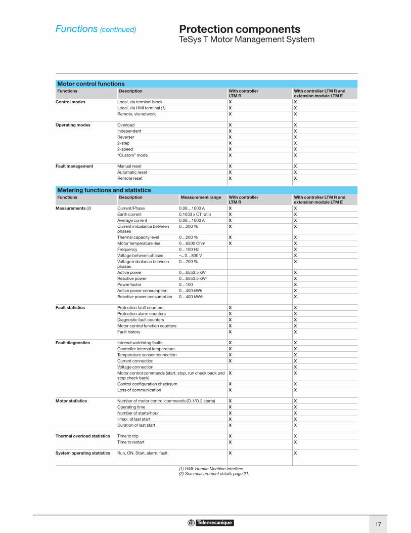
Motor control functionsrellortnoc htiWnoitpircseDsnoitcnuF
LTM RWith controller LTM R and extension module LTM E
Control modes Local, via terminal block XXLocal, via HMI terminal (1) XXRemote, via network XX
Operating modes Overload XXIndependent XXReverser XX2-step XX2-speed XX“Custom” mode XX
Fault management Manual reset XXAutomatic reset XXRemote reset XX
Metering functions and statisticsFunctions Description Measurement range With controller
LTM RWith controller LTM R and extension module LTM E
Measurements (2) Current/Phase 0.08…1000 A XXEarth current 0.1633 x CT ratio XXAverage current 0.08…1000 A XXCurrent imbalance between phases
0…200 % XX
Thermal capacity level 0…200 % XXMotor temperature rise 0…6500 Ohm XXFrequency 0…100 Hz XVoltage between phases a 0…830 V XVoltage imbalance between phases
0…200 % X
Active power 0…6553.5 kW XReactive power 0…6553.5 kWr XPower factor 0…100 XActive power consumption 0…400 kWh XReactive power consumption 0…400 kWrh X
Fault statistics Protection fault counters XXProtection alarm counters XXDiagnostic fault counters XXMotor control function counters XXFault history XX
Fault diagnostics Internal watchdog faults XXController internal temperature XXTemperature sensor connection XXCurrent connection XXVoltage connection XMotor control commands (start, stop, run check back and stop check back)
XX
Control confi guration checksum XXLoss of communication XX
Motor statistics Number of motor control commands (O.1/O.2 starts) XXOperating time XXNumber of starts/hour XXI max. of last start XXDuration of last start XX
Thermal overload statistics Time to trip XXTime to restart XX
System operating statistics Run, ON, Start, alarm, fault. XX
(1) HMI: Human Machine Interface.(2) See measurement details page 21.
Functions (continued) 6
17
Protection components 6
TeSys T Motor Management System
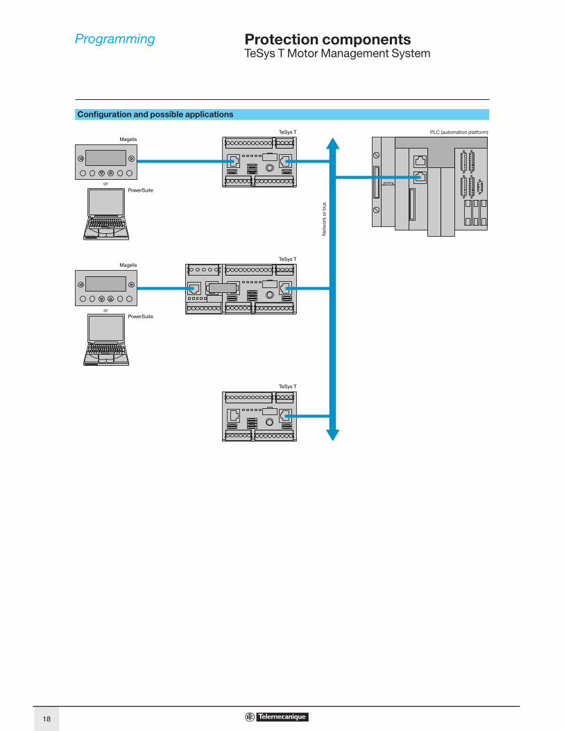
Configuration and possible applications
Magelis
Magelis
TeSys T
TeSys T
TeSys T
PowerSuite
PowerSuite
PLC (automation platform)
Netw
ork
or b
us
or
or
Programming 6
18

Protection components 6
TeSys T Motor Management System
Configuration using PowerSuite The TeSys T configurator will be incorporated in the PowerSuite software
application as from version 2.5.
It allows configuration, commissioning and maintenance of motor starters
protected by TeSys T.
A library containing predefined motor control mode functions is available in order to:
b allow standardisation,
b avoid errors and
b reduce motor starter setup times.
5 predefined motor control modes are incorporated in the controller:
b overload mode: monitoring of motors whose control is not managed by the
controller,
b independent mode: starting of non-reversing motors,
b reverser mode: starting of reversing motors,
b 2-step mode: 2-step starting of motors (star-delta, by autotransformer and by
resistor),
b 2-speed mode: 2-speed starting (Dahlander (single winding) or separate winding.
By using logic functions, a “Custom” mode makes it possible to:
b easily adapt these predefined motor control mode functions to the specifi c needs
of your applications,
b create a link with the motor starter environment or
b create new functions.
The functions thus defined can be saved and used to build your function library for
future applications.
To create special functions, a logic editor is incorporated in the confi gurator and
allows a choice of 2 programming languages:
b function block,
b structured text.
536195
Example of TeSys T configurator setup screen
536196
Example of logic editor screen.
Programming (continued) 6
19
Protection components 6
TeSys T Motor Management System
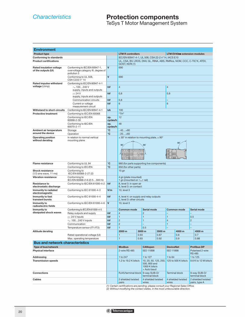
EnvironmentProduct type LTM R controllers LTM EV40pp extension modules
Conforming to standards IEC/EN 60947-4-1, UL 508, CSA 22-2 n°14, IACS E10
Product certifi cations UL, CSA, BV, LROS, DNV, GL, RINA, ABS, RMRos, NOM, CCC, C-TIC’K, ATEX, GOST, KERI (1)
Rated insulation voltage
of the outputs (Ui)Conforming to IEC/EN 60947-1,overvoltage category III, degree of pollution 3
V 690
Conforming to UL 508,CSA C222 n° 14
V 690
Rated impulse withstand
voltage (Uimp)Conforming to IEC/EN 60947-4-1
a 100…240 V supply, inputs and outputs
kV 4 4
c 24 Vsupply, inputs and outputs
kV 0,8 0,8
Communication circuits kV 0,8 –
Current or voltage measurement circuit
kV 6 6
Withstand to short-circuits Conforming to IEC/EN 60947-4-1 kA 100
Protective treatment Conforming to IEC/EN 60068 “TH”
Conforming to IEC/EN 60068-2-30
op.
cycles/h
12
Conforming to IEC/EN 60070-2-11
op.
cycles/h
48
Ambient air temperature
around the device
Storage °C - 40…+80
Operation °C - 20…+60
Operating position
without derating
In relation to normal vertical mounting plane
± 30° in relation to mounting plate, ± 90°
Flame resistance Conforming to UL 94 °C 960 (for parts supporting live components)
Conforming to IEC/EN °C 650 (for other parts)
Shock resistance
(1/2 sine wave, 11 ms)Conforming to IEC/EN 60068-2-27 (2)
15 gn
Vibration resistance Conforming toIEC/EN 60068-2-6 (2) 5…300 Hz
4 gn (plate mounted)1 gn (mounted on 5 rail)
Resistance to
electrostatic discharge
Conforming to IEC/EN 61000-4-2 kV 8, level 3: in open air6, level 3: on contact:
Immunity to radiated
electromagnetic
Conforming to IEC 61000-4-3 V/m 10, level 3
Immunity to fast
transient bursts
Conforming to IEC 61000-4-4 kV 4, level 4: on supply and relay outputs2, level 3: other circuits
Immunity to
radioelectric fi elds
Conforming to IEC/EN 61000-4-6 V 10, level 3
Immunity to
dissipated shock waves
Conforming to IEC/EN 61000-4-5 Common mode Serial mode Common mode Serial mode
Relay outputs and supply kV 4 2 – –
c 24 V inputs kV 1 1 1 0.5
a 100…240 V inputs kV 2 1 4 2
Communication kV 2 – 1 –
Temperature sensor (IT1/IT2) kV 1 0.5 – –
Altitude derating 2000 m 3000 m 3500 m 4000 m 4500 m
Rated operational voltage (Ui) 1 0.93 0.87 0.8 0.7
Max. operating temperature 1 0.93 0.92 0.9 0.88
Bus and network characteristicsType of bus/network Modbus CANopen DeviceNet Profi bus DP
Physical interface 2-wire RS 485 ISO 11898 ISO 11898 Polarised 2-wire RS 485
Addressing 1 to 247 1 to 127 1 to 64 1 to 125
Transmission speeds 1.2 to 19.2 K bits/s 10, 20, 50, 125, 250, 500, 800 and 1000 K bits/s+ Auto baud
125 to 500 K bits/s 9.6 K to 12 M bits/s
Connections RJ45/terminal block 9-way SUB-D/terminal block
Terminal block 9-way SUB-D/terminal block
Cables 2 shielded twisted pairs
4 shielded twisted wires
4 shielded twisted wires
2 shielded twisted pairs, type A
(1) Certain certifications are pending; please consult your Regional Sales Offi ce.(2) Without modifying the contact states, in the most unfavourable direction.
Characteristics 6
20

Protection components 6
TeSys T Motor Management System
Controller and extension module characteristicsProduct type Controllers Extension modules
LTM RpppBD LTM RpppFM LTM EV40BD LTM EV40FM
Control supply
Operational voltage (U) Conforming to IEC/EN 60947-1
V c 24 a 100…240 –
Resistance to voltage dips Conforming to IEC/EN 61000-4-11
V 0 for 3 ms70% of U for 500 ms
–
Associated protection A gG fuse, 0.5 –
Operational voltage V c 20.4…26.24 a 93.5…264 –
Current consumption 50/60 Hz mA c 56…127 a 8…62.8 –
Cabling
Connectors Pitch mm 5.08 5.08
Flexible cable without cable end 1 conductor mm2 0.2…2.5 0.2…2.5
2 identical conductors mm2 0.2…1.5 0.2…1.5
Flexible cable with cable end
Without insulated ferrule 1 conductor mm2 0.25…2.5 0.25…2.5
2 identical conductors mm2 0.5…1.5 0.5…1.5
With insulated ferrule 1 conductor mm2 0.25…2.5 0.25…2.5
2 identical conductors mm2 0.2…1 0.2…1
Solid cable without cable end 1 conductor mm2 0.2…2.5 0.2…2.5
2 identical conductors mm2 0.2…1 0.2…1
Conductor size AWG 24 to AWG 14 AWG 24 to AWG 14
Tightening torque N.m 0.5…0.6 0.5…0.6
Flat screwdriver mm 3 3
Input characteristics
Nominal values Conforming to IEC/EN 61131-1 Type 1 positive logic (c: resistive, a: capacitive)
Voltage V c 24 a 100…240 c 24 a 100…240
Current mA c 7 a 3.1 for 100 Va 7.5 for 240 V
c 7 a 3.1 for 100 Va 7.5 for 240 V
Logic inputs Logic state 1 Voltage V 15 max 79 < U < 264 15 max 79 < U < 264
Current mA 2 min…15 max 2 min at 110 V…3 min at 220 V
2 min…15 max 2 min at 110 V…3 min at 220 V
Logic state 0 Voltage V 5 max 0 < U < 40 5 max 0 < U < 40
Current mA 15 max 15 max 15 max 15 max
Response time Change to state 1 ms 15 25 15 25
Change to state 0 ms 5 25 5 25
Output characteristics
Type Volt free, single break
Load a 250 V / 5 A B300
c 30 V / 5 A
Permissible power in cat. AC-15 For 500 000 operating cycles VA 480 / Ie max: 2 A
Permissible power in cat. DC-13 For 500 000 operating cycles W 30 / Ie max: 1.25 A
Associated protection A gG fuse, 4
Max. frequency Hz 2
Max. operating level op.
cycles/h
1800
Response time Change to state 1 ms 10 max
Change to state 0 ms 10 max
Measurement details
Current 1 % for the 0.4…8 A and 1.35…27 A ranges2 % for the 5…100 A range
Voltage 1% from 100 to 830 V
Earth fault current Internal measurement without earth fault toroid
5…15 % for current > 0.1 A in the 0.4…8 A rangecurrent > 0.2 A in the 1.35…27 A rangecurrent > 0.3 A in the 5…100 A range
External measurement with earth fault toroid
< 5 % or 0.01 A
Temperature measurement 2 %
Power factor 3 % for a Cos ϕ> 0.6
Active and reactive power 5 %
Internal clock ± 30 min / year
Characteristics (continued) 6
21

Protection components 6
TeSys T Motor Management System
LT6 CTpppp external current transformer characteristicsConforming to standards IEC 60185, BS 7626
Precision Class 5P
Precision limit factor 15
Rated insulation voltage
(Ui)690
Maximum operating temperature °C 50
Transformer ratio A 100/1 200/1 400/1 800/1
Diameter of conductor passage hole mm 35 35 35 35
Maximum cabling c.s.a. mm2 30 x 10 30 x 10 30 x 10 incorporated (1)
Earth fault toroid characteristicsToroid type 50437 50438 50439 50440 50441 50442 50485 50486
Rated insulation voltage Ui V 1000
Operating temperature °C - 35…+ 70
Protection index IP30 (connections IP20)
Transformer ratio 1/1000
Rated operational current le A 65 85 160 250 400 630 85 250
Max. conductor c.s.a. per phase mm2 25 50 95 240 2 x 185
2 x 240
50 240
DA1 TTpp probe characteristicsConforming to standards IEC 60034-11 mark A
Economy resistor At 25 °C Ω 3 x 250 in series
Rated operational voltage
(Ue)Per probe V c 2.5 max
Rated insulation voltage
(Ui)kV 2.5
Insulation Reinforced
Length of connecting cables Between probes mm 250
Between probe and motor terminal plate
m 1
Guaranteed operating zones: example with 3 probes type DA1 TTppp (250 Ω at 25 °C) in series, conforming to standard EC 60034-11, mark A.
1 3 probes type DA1 TTppp (250 Ω at 25 °C) in series.
NOT: Nominal Operating Temperature
Protection unit tripped.
Protection unit reset.
(1) Electrical connection to be made using M10 bolt.
10 000
4000
100
10
-20
20
7501000
16501500
0
1
Economy resistor
(ohms)
Trip zone
Reset zone
Trip zone on
probe short-circuit
Temperature (°C)
NO
T +
15
°C
NO
T +
5 °
C
NO
T -
20
°C
NO
T -
5 °
CN
OT
Characteristics (continued) 6
22

Protection components 6
TeSys T Motor Management System
Cold state curves
Hot state curves
10 000
1000
100
10
1
t (s)
I/Ir1 1,12 1,5 2 3 4 5 6 7 8
Class 5
Class 10
Class 15
Class 20
Class 25Class 30
10 000
1000
100
10
1
t (s)
I/Ir1 1,12 1,5 2 3 4 5 6 7 8
Class 5
Class 10
Class 15
Class 20
Class 25
Class 30
Tripping curves 6
23
Protection components 6
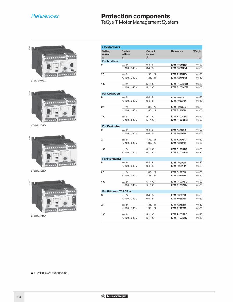
TeSys T Motor Management System
ControllersSetting
range
Control
voltage
Current
ranges
Reference Weight
A V A kg
For Modbus
8 c 24 0.4…8 LTM R08MBD 0.530
a 100…240 V 0.4…8 LTM R08MFM 0.530
27 c 24 1.35…27 LTM R27MBD 0.530
a 100…240 V 1.35…27 LTM R27MFM 0.530
100 c 24 5…100 LTM R100MBD 0.530
a 100…240 V 5…100 LTM R100MFM 0.530
For CANopen
8 c 24 0.4…8 LTM R08CBD 0.530
a 100…240 V 0.4…8 LTM R08CFM 0.530
27 c 24 1.35…27 LTM R27CBD 0.530
a 100…240 V 1.35…27 LTM R27CFM 0.530
100 c 24 5…100 LTM R100CBD 0.530
a 100…240 V 5…100 LTM R100CFM 0.530
For DeviceNet
8 c 24 0.4…8 LTM R08DBD 0.530
a 100…240 V 0.4…8 LTM R08DFM 0.530
27 c 24 1.35…27 LTM R27DBD 0.530
a 100…240 V 1.35…27 LTM R27DFM 0.530
100 c 24 5…100 LTM R100DBD 0.530
a 100…240 V 5…100 LTM R100DFM 0.530
For Profi busDP
8 c 24 0.4…8 LTM R08PBD 0.530
a 100…240 V 0.4…8 LTM R08PFM 0.530
27 c 24 1.35…27 LTM R27PBD 0.530
a 100…240 V 1.35…27 LTM R27PFM 0.530
100 c 24 5…100 LTM R100PBD 0.530
a 100…240 V 5…100 LTM R100PFM 0.530
For Ethernet TCP/IP r
8 c 24 0.4…8 LTM R08EBD 0.530
a 100…240 V 0.4…8 LTM R08EFM 0.530
27 c 24 1.35…27 LTM R27EBD 0.530
a 100…240 V 1.35…27 LTM R27EFM 0.530
100 c 24 5…100 LTM R100EBD 0.530
a 100…240 V 5…100 LTM R100EFM 0.530
LTM R08MBD
105836
LTM R08CBD
105838
LTM R08DBD
105840
LTM R08PBD
105842
r : Available 3rd quarter 2008.
References 6
24

Protection components 6
TeSys T Motor Management System
Extension modules, with voltage measurement on the 3 phases
Input
control
voltage
Number
of inputs
Supply to
the electronics
Reference Weight
V kg
c 24 4 Via the controller LTM EV40BD 0.210
a 100…240 4 Via the controller LTM EV40FM 0.210
HMI terminalDescription Supply voltage Reference Weight
kg
Magelis compact display
With matrix display4 lines of 20 characters.
c 24 V external XBT N410 0.380
Description Number and type
of connectors
Reference Weight
kg
Connecting cable (2.5 m)
For connecting the XBT N410 display unit to TeSys T.
SUB-D 25-way femaleRJ45
XBT Z938 0.200
CablesDescription Number and type
of connectors
Length Reference Weight
m kg
Connecting cables
For connecting the controller to the extension module
2 x RJ45 0.04 LTM CC004 (1) 0.120
0.3 LU9 R03 0.045
1 LU9 R10 0.065
Replacement connectorsDescription Number and type
of connectors
Reference Weight
kg
Complete set of connectors
for the controllers and
extension modules
10 screw terminals(all network versions included)
LTM 9TCS 0.200
(1) Sold in lots of 6.
LTM EV40BD
105846
References (continued) 6
25
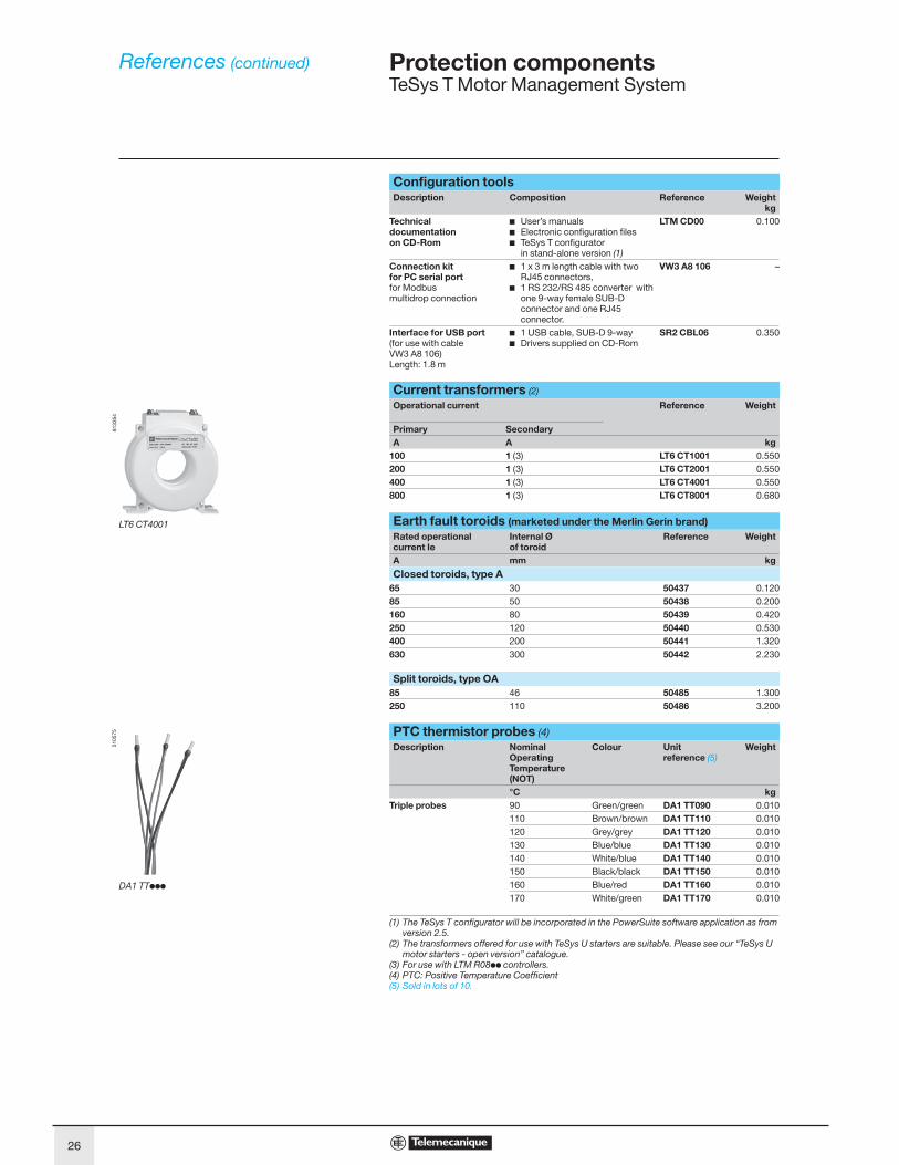
Protection components 6 TeSys T Motor Management System
Confi guration toolsthgieWecnerefeRnoitisopmoCnoitpircseD
kgTechnical documentation on CD-Rom
b User’s manualsb Electronic confi guration fi lesb TeSys T confi gurator
in stand-alone version (1)
LTM CD00 0.100
Connection kit for PC serial portfor Modbus multidrop connection
b 1 x 3 m length cable with two RJ45 connectors,
b 1 RS 232/RS 485 converter with one 9-way female SUB-D connector and one RJ45 connector.
VW3 A8 106 –
Interface for USB port(for use with cable VW3 A8 106)Length: 1.8 m
b 1 USB cable, SUB-D 9-wayb Drivers supplied on CD-Rom
SR2 CBL06 0.350
Current transformers (2)
thgieWecnerefeRtnerruc lanoitarepO
Primary SecondarygkAA
1001TC 6TL)3( 1001 0.5501002TC 6TL)3( 1002 0.550
1004TC 6TL)3( 1004 0.5501008TC 6TL)3( 1008 0.680
Earth fault toroids (marketed under the Merlin Gerin brand)Rated operational current Ie
Internal Ø of toroid
Reference Weight
gkmmA
Closed toroids, type A65 30 50437 0.12085 50 50438 0.200160 80 50439 0.420250 120 50440 0.530400 200 50441 1.320630 300 50442 2.230
Split toroids, type OA85 46 50485 1.300250 110 50486 3.200
PTC thermistor probes (4)Description Nominal
Operating Temperature (NOT)
Colour Unit reference (5)
Weight
gkC°Triple probes 90 Green/green DA1 TT090 0.010
110 Brown/brown DA1 TT110 0.010120 Grey/grey DA1 TT120 0.010130 Blue/blue DA1 TT130 0.010140 White/blue DA1 TT140 0.010150 Black/black DA1 TT150 0.010160 Blue/red DA1 TT160 0.010170 White/green DA1 TT170 0.010
(1) The TeSys T confi gurator will be incorporated in the PowerSuite software application as from version 2.5.
(2) The transformers offered for use with TeSys U starters are suitable. Please see our “TeSys U motor starters - open version” catalogue.
(3) For use with LTM R08pp controllers.(4) PTC: Positive Temperature Coeffi cient(5) Sold in lots of 10.
LT6 CT4001
8133
54
DA1 TTppp
5105
75
References (continued) 6
26

Protection components 6
TeSys T Motor Management System
Marking accessories (to be ordered separately)
Description Composition Sold in
lots of
Unit
reference
Weight
kg
Clip-in markers
(maximum of 5 per unit)Strips of 10 identical numbers (0 to 9)
25 AB1 Rp (1) 0.002
Strips of 10 identical capital letters (A to Z)
25 AB1 Gp (1) 0.002
Connection accessoriesDescription Length Reference Weight
m kg
For Modbus connection
Cables fitted with 2 x RJ45 connectors 0.3 VW3 A8 306 R03 0.045
1 VW3 A8 306 R10 0.065
3 VW3 A8 306 R30 0.125
T-junctions 0.3 VW3 A8 306 TF03 0.032
1 VW3 A8 306 TF10 0.032
RS 485 line terminator – VW3 A8 306 R 0.012
For CANopen connection (2)
Cables 50 TSX CAN CA50 4.930
100 TSX CAN CA100 8.800
300 TSX CAN CA300 24.560
IP20 connectors
9-way SUB-D femaleLine end adapter switch
Elbowed (90°) – TSX CAN KCDF 90T 0.046
Straight – TSX CAN KCDF 180T 0.049
Elbowed (90°) with SUB-D 9-way connector for connection to PC or diagnostic tool
– TSX CAN KCDF 90TP 0.051
For DeviceNet connection
Cables 50 TSX CAN CA50 4.930
100 TSX CAN CA100 8.800
300 TSX CAN CA300 24.560
For Profibus DP connection
Cables 100 TSX PBSCA100 –
400 TSX PBSCA400 –
Connectors With line terminator – 490 NAD 011 03 –
Without line terminator – 490 NAD 011 04 –
With line terminator and terminal port
– 490 NAD 011 05 –
(1) When ordering, replace the p in the reference with the number or letter required.(2) To order other connectors and cables (UL cables for harsh environments, etc.) please consult
our catalogue “Machines and installations with CANopen. Performance and fl exibility”.
References (continued) 6
27

Protection components 6
TeSys T Motor Management System
LTM Rpp controllers
LTM EV40pp extension modules
(1) 140 mm with RJ45 connector for connection to extension module and to network.166 mm with Profibus DP/CANopen connector.
(2) Leave a gap around the device of: 9 mm at 45°C, 9 to 40 mm from 45 to 50 °C, 40 mm at 60°C.
5,2 91
(2) (2)
122,5 (1)
61
30,2
(2)
(2)
5,5 45
120,7 (1)
61
30,2
Dimensions,mounting 6
28

Protection components 6
TeSys T Motor Management System
Current transformers HMI terminalLT6 CT XBT N410
(1) 104 mm with fixing clips (supplied with the product).(2) 58 mm with SUB-D 25-way elbowed cable XBT Z9680 for Twido, TSX Micro and Premium
or XBT Z998 for Advantys STB.
Earth fault toroids50437 and 50438 50439, 50440 and 50441
Type b b1 Øc c1 c2 H Type a a1 Øb b1 b2 Øc c1 G H J K50437 83 53 30 60 31 50 50439 26.5 44 122 80 55 80 150 35 65 126 40
50438 109 66 50 87 45 60 50440 26.5 44 164 80 55 120 190 35 65 166 40
50441 29 46 256 120 90 196 274 37 104 254 60
50442 50485 and 50486
Type a Øb Øc G50485 72 148 46 57
50486 78 224 110 76
2,5
35255 525
95
35 107
3042
1010
2,5
20
42,5 42,55 5
132
74 (
1)
6
(2)
c1
c2
8
H
b1
b
29
21
4
16
H
a
G
a1
J
c1
b2Kb1
344
29299
a
G
Dimensions (continued) 6
29

Protection components 6
TeSys T Motor Management System
SchemesOverload mode3-wire local-control
Independent mode3-wire local-control
2-wire local-control 3-wire with switchable local/network control 2-wire with switchable local/network control
L: Local controlO: StopN: Network control
LTM R24 33 3413 14 23
96959897I.6CI.5I.4CI.3I.2CI.1A2
A1
– KM1
+/a–/a
– KM1
O.1 O.2 O.3
O.4
M 3
3 a
Stop
Start
LTM R24 33 3413 14 23
96959897I.6CI.5I.4CI.3I.2CI.1A2
A1
– KM1
+/a–/a
O.1 O.2 O.3
O.4
M 3
– KM1
3 a
Stop
Start
96959897I.6CI.5I.4CI.3I.2CI.1
O.4
Start/Stop
96959897I.6CI.5I.4CI.3I.2CI.1
O.4
NL O
Start
Stop
96959897I.6CI.5I.4CI.3I.2CI.1
O.4
NL O
Schemes 6
30

Protection components 6
TeSys T Motor Management System
Schemes (continued)Reverser mode3-wire local-control
2-step mode, star-delta application3-wire local-control
(1) Contacts for interlocking KM1 and KM2 are not obligatory because the controller electronically interlocks outputs O.1 and O.2.
LTM R24 33 3413 14 23
96959897I.6CI.5I.4CI.3I.2CI.1A2
A1
– KM2 – KM1
+/a–/a
– KM1
– KM2
– KM2
– KM1 (1)
O.1 O.2 O.3
O.4
3 a
M 3
StopStart
Forw
Start
Rev
LTM R24 33 3413 14 23
96959897I.6CI.5I.4CI.3I.2CI.1A2
A1
– KM2 – KM3
+/a–/a
– KM1
– KM3 – KM3
– KM2 – KM3
– KM1– KM1 (1)
O.1 O.2 O.3
O.4
3 a
– KM1
M 3
StopStart
Schemes (continued) 6
31

Protection components 6
TeSys T Motor Management System
Schemes (continued)2-step mode, primary resistor application3-wire local-control
2-speed mode, Dahlander application3-wire local-control
(1) For a Dahlander application, all the power cables must pass through current transformers. The controller can also be placed upstream of the contactor. In this case, and if the Dahlander motor is used in “variable torque” mode, all the cables downstream of the contactors must be of identical size.
(2) Contacts for interlocking KM1 and KM2 are not obligatory because the controller electronically interlocks outputs O.1 and O.2.
LTM R24 33 3413 14 23
96959897I.6CI.5I.4CI.3I.2CI.1A2
A1
– KM2 – KM1
+/a–/a
– KM1 – KM2
O.1 O.2 O.3
O.4
3 a
M 3
StopStart
LTM R24 33 3413 14 23
96959897I.6CI.5I.4CI.3I.2CI.1A2
A1
– KM1 – KM3
+/a–/a
O.1 O.2 O.3
O.4
3 a
– KM1
– KM2
– KM2 – KM3
– KM2– KM1 (2)
(1)
– KM2
M 3
Low
speed
High
speed Stop
Schemes (continued) 6
32

Protection components 6
TeSys T Motor Management System
Schemes (continued)Earth fault toroid and motor temperature probe connection
Connection of outputs for motor control mode functionWithout intermediate relay With intermediate relay
24 33 3413 14 23
O.1 O.2
Z1 Z2 T1 T2
O.3
LTM R
M 3
LTM R13 14
– KM1
+/a
–/a
O.1
– KM1
3 a
M 3
LTM R13 14
– KM1
+/a
–/a
O.1
– KA1 – KM1
3 a
Schemes (continued) 6
33

Protection components 1
TeSys T Motor Management System
Combinations providing type 2 coordination
With circuit-breaker
Standard power ratings of 3-phase motors 50/60 Hz
in category AC-3 400/415 V
Circuit-breaker Contactor TeSys T
controller
External current
transformer
P
kW
Ie
A
Icc
kA
Reference Reference Reference Reference
0,06 0,22 130 GV2 L03 LC1 D09 LTM R08pp –
0,09 0,36 130 GV2 L03 LC1 D09 LTM R08pp –
0,12 0,42 130 GV2 L04 LC1 D09 LTM R08pp –
0,18 0,62 130 GV2 L04 LC1 D09 LTM R08pp –
0,25 0,88 130 GV2 L05 LC1 D09 LTM R08pp –
0,37 0,98 130 GV2 L05 LC1 D09 LTM R08pp –
0,55 1,6 130 GV2 L06 LC1 D09 LTM R08pp –
0,75 2 130 GV2 L07 LC1 D09 LTM R08pp –
1,1 2,5 130 GV2 L07 LC1 D18 LTM R08pp –
1,5 3,5 130 GV2 L08 LC1 D18 LTM R08pp –
2,2 5 130 GV2 L10 LC1 D18 LTM R08pp –
3 6,5 130 GV2 L14 LC1 D18 LTM R08pp –
4 8,4 130 GV2 L14 LC1 D18 LTM R27pp –
5,5 11 130 GV2 L16 LC1 D25 LTM R27pp –
7,5 14,8 50 GV2 L20 LC1 D25 LTM R27pp –
9 18,1 50 GV2 L22 LC1 D25 LTM R27pp –
11 21 50 GV2 L22 LC1 D25 LTM R27pp –
15 28,5 70 NS80HMA LC1 D50 LTM R100pp –
18,5 35 70 NS80HMA LC1 D40 LTM R100pp –
22 42 70 NS80HMA LC1 D50 LTM R100pp –
30 57 70 NS80HMA LC1 D65 LTM R100pp –
37 69 70 NS80HMA LC1 D80 LTM R100pp –
45 81 25 NS100HMA LC1 D115 LTM R100pp –
45 81 70 NS100HMA LC1 D115 LTM R100pp –
55 100 36 NS160NMA LC1 D115 LTM R100pp –
55 100 70 NS160HMA LC1 D115 LTM R100pp LT6 CT2001
75 135 36 NS160NMA LC1 D150 LTM R08pp LT6 CT2001
75 135 70 NS160HMA LC1 D150 LTM R08pp LT6 CT2001
90 165 36 NS250NMA LC1 F185 LTM R08pp LT6 CT2001
90 165 70 NS250HMA LC1 F185 LTM R08pp LT6 CT2001
110 200 36 NS250NMA LC1 F225 LTM R08pp LT6 CT2001
110 200 70 NS250HMA LC1 F225 LTM R08pp LT6 CT2001
132 240 70 NS400HMA LC1 F265 LTM R08pp LT6 CT4001
132 240 130 NS400LMA LC1 F265 LTM R08pp LT6 CT4001
160 285 70 NS400HMA LC1 F330 LTM R08pp LT6 CT4001
160 285 130 NS400LMA LC1 F330 LTM R08pp LT6 CT4001
200 352 70 NS630HMA LC1 F400 LTM R08pp LT6 CT4001
200 352 130 NS630LMA LC1 F400 LTM R08pp LT6 CT4001
220 388 70 NS630HMA LC1 F500 LTM R08pp LT6 CT4001
220 388 130 NS630LMA LC1 F500 LTM R08pp LT6 CT4001
250 437 70 NS630HMA LC1 F500 LTM R08pp LT6 CT6001
250 437 130 NS630LMA LC1 F500 LTM R08pp LT6 CT6001
Substitution table
Old range
LT6 P multifunction protection relays
New range
TeSys T controllers
Motor current Reference Reference External current
transformer
Reference
Reference Reference External current
transformer
Reference
a 100…240 V c 24 V a 100…240 V c 24 V
I < 5 A LT6 P0M005FM LT6 P0M005S144 – LTM R08pFM LTM R08pBD –
5 A < I < 25 A LT6 P0M025FM LT6 P0M025S144 – LTM R27pFM LTM R27pBD –
25 A < I < 100 A LT6 P0M005FM LT6 P0M005S144 LT6 CT1001 LTM R100pFM LTM R100pBD –
100 A < I < 200 A LT6 P0M005FM LT6 P0M005S144 LT6 CT2001 LTM R08pFM LTM R08pBD LT6 CT2001
200 A < I < 400 A LT6 P0M005FM LT6 P0M005S144 LT6 CT4001 LTM R08pFM LTM R08pBD LT6 CT4001
400 A < I < 800 A LT6 P0M005FM LT6 P0M005S144 LT6 CT8001 LTM R08pFM LTM R08pBD LT6 CT8001
Note: For other voltages and combinations with fuses, please consult your Regional Sales Offi ce.
CombinationsSubstitution table
34

35
Notes

36
Notes

37
Notes

Simply Smart!The efficiency of Telemecaniquebranded solutionsUsed in combination, Telemecanique products provide qualitysolutions, meeting all your automation and control applicationsrequirements.
A unique partner and a worldwide presence
Worldwide availability
More than 5,000 points of sale in 130 countries.
You can be sure to find a range of products that meets yourneeds and fully complies with the standards in the countryin which they will be used.
Schneider Electric’s regional focus 200 dedicated sales engineers operate from
22 regional sales centres and 13 technical service centres across Canada.
Our sales engineers are skilled at assessing individualrequirements. Combined with the expert support of our product specialists, they will develop the most effective andeconomical solution for you, taking relevant regulationsand standards into account.
© 2
007
Sch
neid
er C
anad
a In
c. A
ll R
ight
s R
eser
ved
.
Schneider Electric
Head Office19 Waterman AvenueToronto, Ontario M4B 1Y2www.schneider-electric.caTel: (416) 752-8020Fax: (416) 752-8944
T9065CT0701EP R0October, 2007
Customer service: (800) 565-6699
Networks & Communication
HMIs
Detection
AutomationMotor controlInterfaces & I/O
Mounting systems
Power supplies
Motion control
Software tools


