IEEE Industry Applications Society – Atlanta ChapterJanuary 19, 2010 Meeting
1
Sakis MeliopoulosGeorgia Power Distinguished ProfessorSchool of Electrical and Computer Engineering,Georgia Institute of Technology,Atlanta, Georgia 30332-0250,Telephone: 404 894-2926, Fax: 404 894-4641Email: [email protected] or [email protected]
Testing and Evaluation of Grounding Systems:The Revision of the IEEE Std 81
IEEE Industry Applications Society – Atlanta ChapterJanuary 19, 2010 Meeting
2
Purpose of Grounding
Lightning and Surge Protection
Stabilize Circuit Potential and Assist in Proper Operation of:
- Communications- Relaying- Computers & Sensitive Electronic Equipment
Low Fault Circuit Path Impedance
Safety, Safety, Safety
Improve Quality of Power Service
Grounding and Bonding is Fundamental for a Safe and Reliable Power System
IEEE Industry Applications Society – Atlanta ChapterJanuary 19, 2010 Meeting
3
Grounding, Bonding and Power Quality“Recent studies indicate that as much as 80% of all failures of sensitive electronic equipment attributed to poor power quality may result from inadequate electrical grounding or wiring on the customer’s premises or from interactions with other loads within the premises.”
Wiring and Grounding for Power QualityEPRI CU-2026, March 1990
“However, many power quality problems that occur within customer facilities are related to wiring and grounding practices. Up to 80% of all power quality problems reported by customers are related to wiring and grounding problems within a facility.”
Power Quality Assessment ProcedureEPRI CU-7529, December 1991
IEEE Industry Applications Society – Atlanta ChapterJanuary 19, 2010 Meeting
4
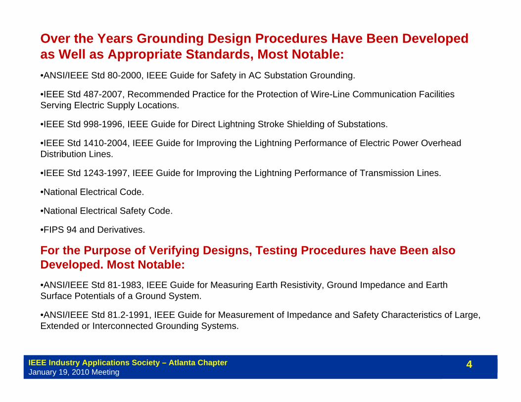
Terms and DefinitionsOver the Years Grounding Design Procedures Have Been Developed as Well as Appropriate Standards, Most Notable:•ANSI/IEEE Std 80-2000, IEEE Guide for Safety in AC Substation Grounding.
•IEEE Std 487-2007, Recommended Practice for the Protection of Wire-Line Communication Facilities Serving Electric Supply Locations.
•IEEE Std 998-1996, IEEE Guide for Direct Lightning Stroke Shielding of Substations.
•IEEE Std 1410-2004, IEEE Guide for Improving the Lightning Performance of Electric Power Overhead Distribution Lines.
•IEEE Std 1243-1997, IEEE Guide for Improving the Lightning Performance of Transmission Lines.
•National Electrical Code.
•National Electrical Safety Code.
•FIPS 94 and Derivatives.
For the Purpose of Verifying Designs, Testing Procedures have Been also Developed. Most Notable:•ANSI/IEEE Std 81-1983, IEEE Guide for Measuring Earth Resistivity, Ground Impedance and Earth Surface Potentials of a Ground System.
•ANSI/IEEE Std 81.2-1991, IEEE Guide for Measurement of Impedance and Safety Characteristics of Large, Extended or Interconnected Grounding Systems.
IEEE Industry Applications Society – Atlanta ChapterJanuary 19, 2010 Meeting
5
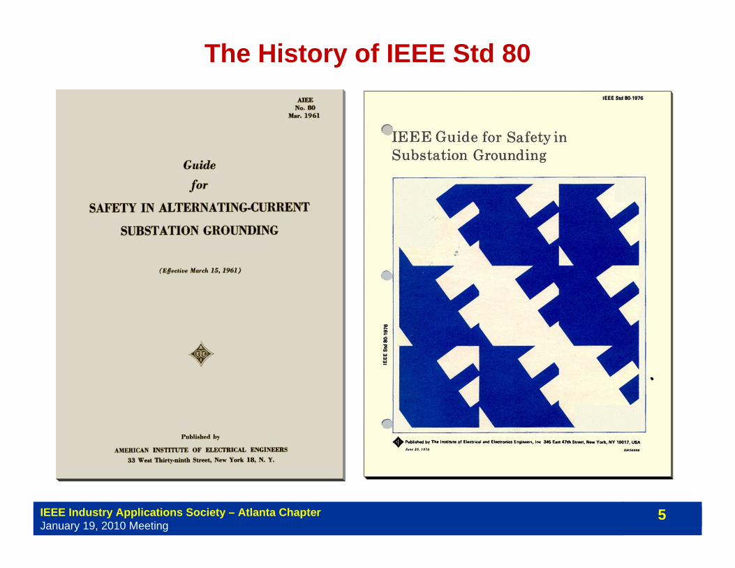
The History of IEEE Std 80

IEEE Industry Applications Society – Atlanta ChapterJanuary 19, 2010 Meeting
6
The History of IEEE Std 80
IEEE Industry Applications Society – Atlanta ChapterJanuary 19, 2010 Meeting
7
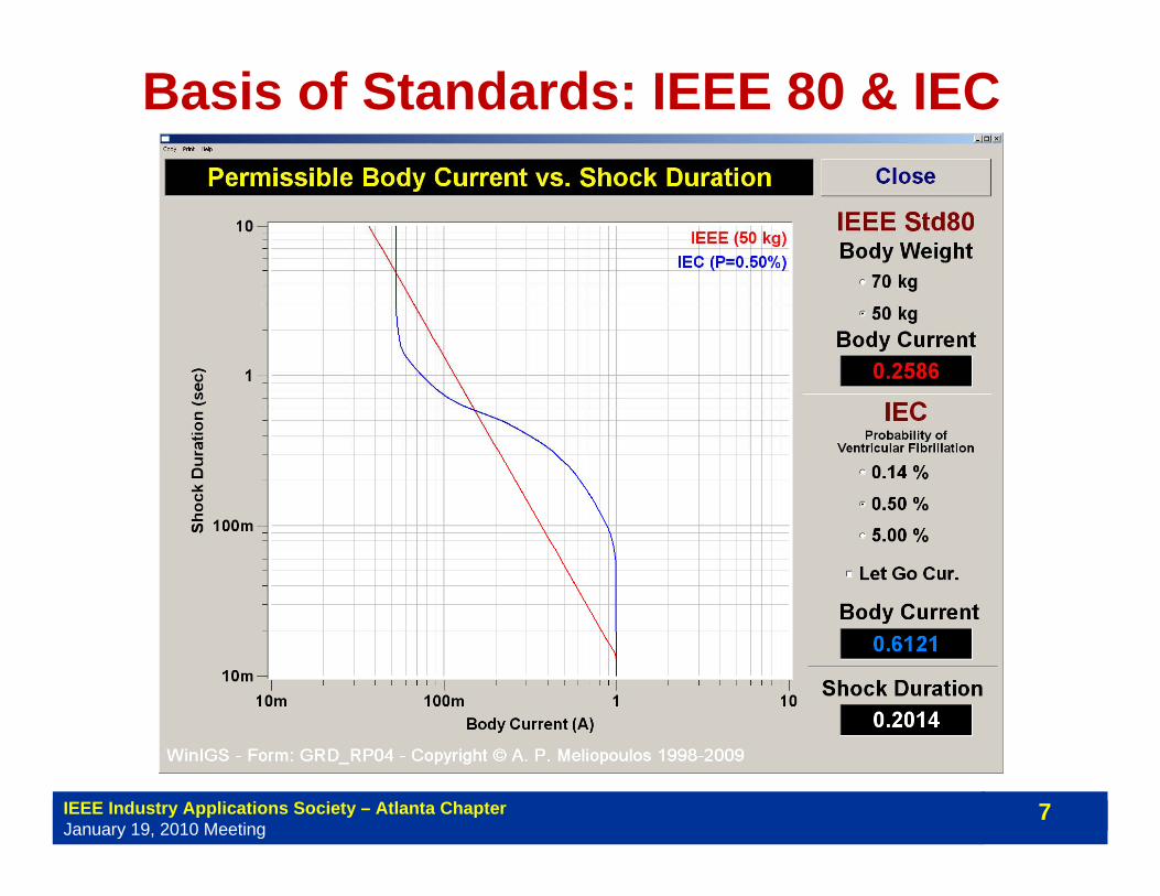
Basis of Standards: IEEE 80 & IECNon-Fibrillating Body Current as a Function of Shock Duration

IEEE Industry Applications Society – Atlanta ChapterJanuary 19, 2010 Meeting
8
k50 = 0.116 (Non-Fibrillating, 0.5%)
k50 = 0.185 (Fibrillating, 0.5%)
k70 = 0.157 (Non-Fibrillating, 0.5%)
k70 = 0.263 (Fibrillating, 0.5%)
sb tIk =
Value of Constant k for EffectiveRMS Values of IB:
Body Weight (kg)
Fibr
illatin
g C
urre
nt (m
A R
MS)
0
100
200
300
0 10020 40 60 80
MaximumNon-FibrillatingCurrent (0.5%)
MinimumFibrillatingCurrent (0.5%)
Dog
s
shee
pca
lves
pigs
Kise
lev
Dog
s
Ferri
s D
ogs
IEEE Std 80, 1986 Edition

IEEE Industry Applications Society – Atlanta ChapterJanuary 19, 2010 Meeting
9
Earth Current, Ground Potential Rise, Touch & Step 1. Determination of Soil Resistivities2. Computation of Ground Potential Rise3. Computation of Surface Voltages (touch and step)4. Safety Assessment
Basic Problems:
secounterpoiearthneutralshieldfault IIIII ~~~~~ +++=
earthmat IRGPR ~=
IEEE Industry Applications Society – Atlanta ChapterJanuary 19, 2010 Meeting
10
Verification - Measurements
Key Fact:Target Values Must be Determined in Design Phase
IEEE Industry Applications Society – Atlanta ChapterJanuary 19, 2010 Meeting
11
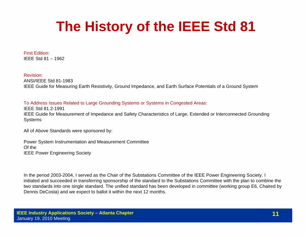
The History of the IEEE Std 81First Edition:IEEE Std 81 – 1962
Revision:ANSI/IEEE Std 81-1983IEEE Guide for Measuring Earth Resistivity, Ground Impedance, and Earth Surface Potentials of a Ground System
To Address Issues Related to Large Grounding Systems or Systems in Congested Areas:IEEE Std 81.2-1991IEEE Guide for Measurement of Impedance and Safety Characteristics of Large, Extended or Interconnected Grounding Systems
All of Above Standards were sponsored by:
Power System Instrumentation and Measurement CommitteeOf the IEEE Power Engineering Society
In the period 2003-2004, I served as the Chair of the Substations Committee of the IEEE Power Engineering Society. I initiated and succeeded in transferring sponsorship of the standard to the Substations Committee with the plan to combine the two standards into one single standard. The unified standard has been developed in committee (working group E6, Chaired by Dennis DeCosta) and we expect to ballot it within the next 12 months.
IEEE Industry Applications Society – Atlanta ChapterJanuary 19, 2010 Meeting
12
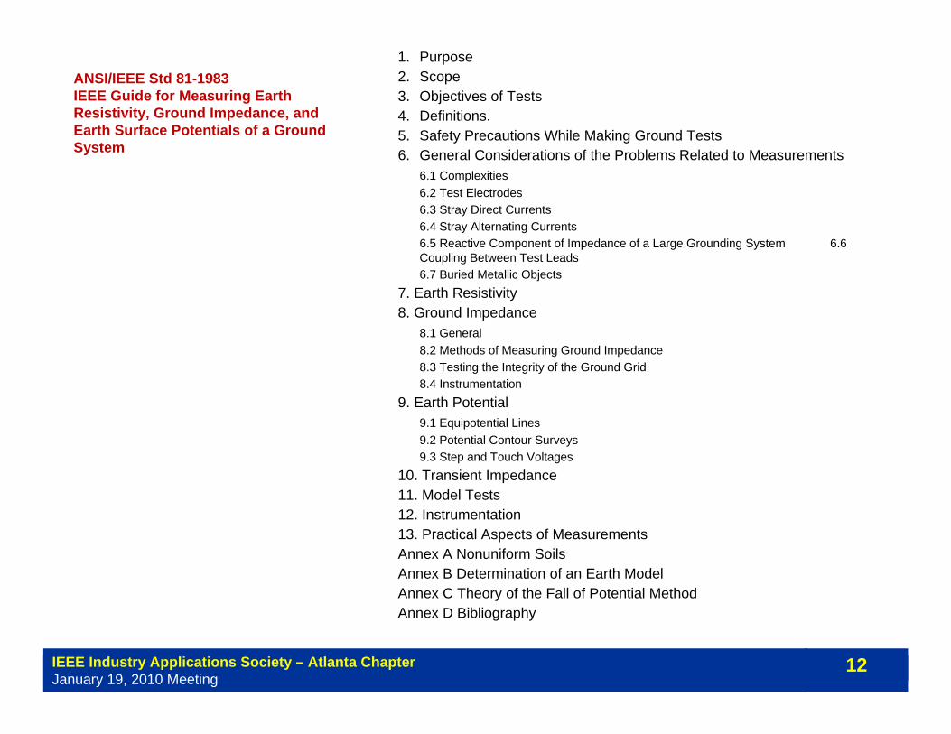
ANSI/IEEE Std 81-1983IEEE Guide for Measuring Earth Resistivity, Ground Impedance, and Earth Surface Potentials of a Ground System
1. Purpose2. Scope3. Objectives of Tests4. Definitions.5. Safety Precautions While Making Ground Tests 6. General Considerations of the Problems Related to Measurements
6.1 Complexities 6.2 Test Electrodes 6.3 Stray Direct Currents 6.4 Stray Alternating Currents 6.5 Reactive Component of Impedance of a Large Grounding System 6.6 Coupling Between Test Leads 6.7 Buried Metallic Objects
7. Earth Resistivity8. Ground Impedance
8.1 General8.2 Methods of Measuring Ground Impedance8.3 Testing the Integrity of the Ground Grid8.4 Instrumentation
9. Earth Potential9.1 Equipotential Lines9.2 Potential Contour Surveys9.3 Step and Touch Voltages
10. Transient Impedance11. Model Tests12. Instrumentation13. Practical Aspects of MeasurementsAnnex A Nonuniform SoilsAnnex B Determination of an Earth ModelAnnex C Theory of the Fall of Potential MethodAnnex D Bibliography

IEEE Industry Applications Society – Atlanta ChapterJanuary 19, 2010 Meeting
13
IEEE Std 81.2-1991IEEE Guide for Measurement of Impedance and Safety Characteristics of Large, Extended or Interconnected Grounding Systems
1. Purpose2. Scope3. References4. Safety Practices5. Factors Effecting Grounding System Measurements6. Preliminary Planning and Procedures7. Earth-Return Mutual Effects When Measuring Grounding-System Impedance
7.1 Introduction7.2 Measurement Error Due to Earth Mutual Resistances7.3 Measurement Error Due to AC Mutual Coupling7.4 Mutual Coupling to Potential Lead From Extended Ground Conductors
8. Measurement of Low-Impedance Grounding Systems by Test-Current Injection8.1 Introduction8.2 Signal Generator and Power Amplifier Source8.3 Portable Power-Generator Source8.4 Power System Low-Voltage Source
9. Measurement of Low-Impedance Grounding Systems by Power System Staged Faults10. Current Distribution in Extended Grounding Systems
10.1 Introduction10.2 Test Considerations10.3 Analysis of Current Distribution in a Grounding System10.4 Induced Current in the Angled Overhead Ground Wire10.5 Current Distribution During a Staged Fault Test
11. Transfer Impedances to Communication or Control Cables12. Step, Touch, and Voltage-Profile Measurements 13. Instrumentation Components
13.5 Fast Fourier Transform Analyzer13.6 Sine Wave Network Analyzer13.7 Staged Fault13.11 Low-Power Random Noise Source13.14 Pulse Generator13.15 Current Transformer (CT)13.16 Resistive Shunt13.17 Inductive Current Pickup13.18 Hall-Effect Probe
14. Instrument Performance Parameters 15. Bibliography
It was developed to address the special problems and issues associated with testing large interconnected grounding systems

IEEE Industry Applications Society – Atlanta ChapterJanuary 19, 2010 Meeting
14
Present RevisionIEEE Std 81-XXXXGuide for Measuring Earth Resistivity, Ground Impedance, and Earth Surface Potentials of a Ground System
1. Overview1.1 Purpose1.2 Scope
2. References3. Definitions4. Test Objectives5. Safety Precautions While Making Ground Tests
5.1 Station Ground Tests5.2 Special Considerations
6. General Considerations on the Problems Related to Measurement7. Earth Resistivity
7.1 General7.2 Methods of Measuring Earth Resistivity7.3 Interpretation of Measurements7.4 Guidance on performing field measurements
8. Ground Impedance9. Testing Local Potential Differences10. Integrity of Grounding Systems11. Current Splits12. Transient Impedance of Grounding System13. OtherANNEX A (INFORMATIVE) SURFACE MATERIAL RESISTIVITYANNEX B - INSTRUMENTATION
B.1. Megohm MeterB.2. Clamp-On Ground TesterB.3. Smart Ground MeterB.4. Transient Impedance Meter

IEEE Industry Applications Society – Atlanta ChapterJanuary 19, 2010 Meeting
15
Grounding System Measurements• Ground Impedance Measurement Methods
The 2-Point MethodThe 3-Point MethodThe Fall of Potential MethodThe 62% RuleThe Ratio MethodThe Tag Slope MethodThe Intersecting Curve MethodStaged Fault TestsDriving Point ImpedanceThe SGM Method
• Continuity/Integrity Testing• Soil Resistivity Measurements• Touch and Step Voltages• Other Tests (Tower/Pole Ground, Transfer V.)

IEEE Industry Applications Society – Atlanta ChapterJanuary 19, 2010 Meeting
16
RaaaaR
aa
ππρ 221
4
2222 4
≅
+−
++
=
llI
VR =
ρ
ρ
1
2
ha a a
VoltMeter
Source CurrentMeter
Earth Surface
l
Four Point – Wenner Method
IEEE Industry Applications Society – Atlanta ChapterJanuary 19, 2010 Meeting
17
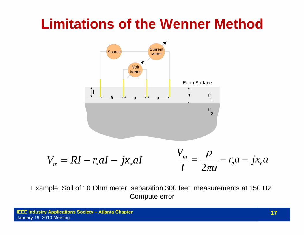
Limitations of the Wenner Method
aIjxaIrRIV eem −−= ajxaraI
Vee
m −−=πρ
2
Example: Soil of 10 Ohm.meter, separation 300 feet, measurements at 150 Hz. Compute error
ρ
ρ
1
2
ha a a
VoltMeter
Source CurrentMeter
Earth Surface
l
IEEE Industry Applications Society – Atlanta ChapterJanuary 19, 2010 Meeting
18
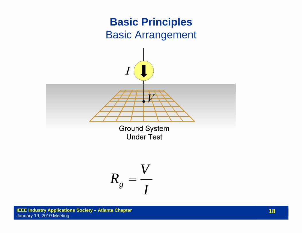
Basic PrinciplesBasic Arrangement
IVRg =
IEEE Industry Applications Society – Atlanta ChapterJanuary 19, 2010 Meeting
19
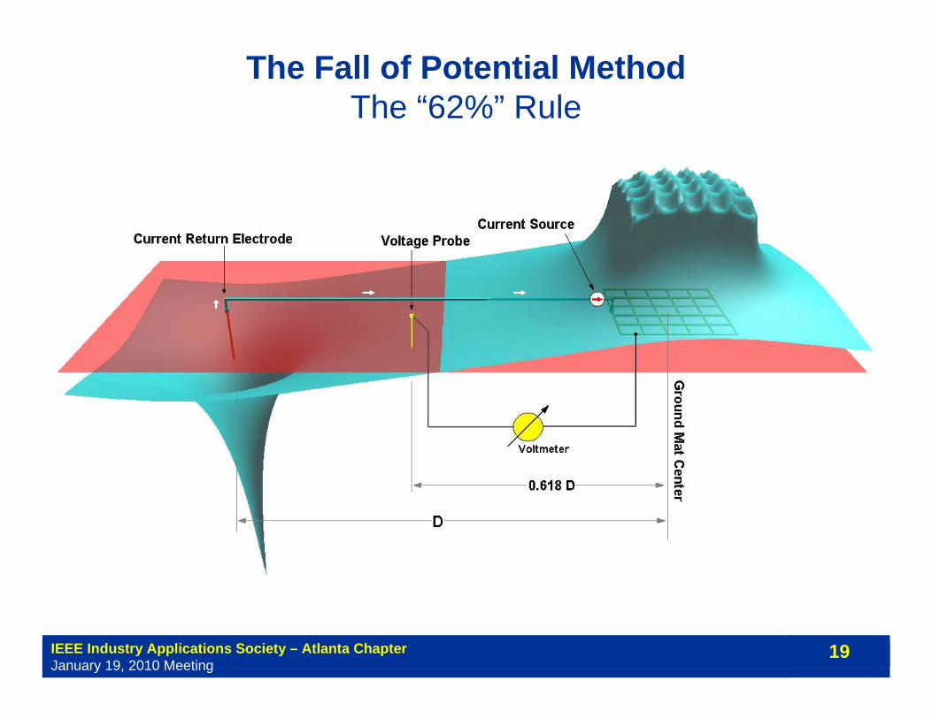
The Fall of Potential MethodThe “62%” Rule

IEEE Industry Applications Society – Atlanta ChapterJanuary 19, 2010 Meeting
20
Optimal Voltage Probe Location – The 62% Rule
⎟⎠⎞
⎜⎝⎛
−−=
rDrIVp
112πρ
⎟⎠⎞
⎜⎝⎛
−+−−=
−=
rDrDaIVV
R paa
11112πρ
⎟⎠⎞
⎜⎝⎛ −=
DaIVa
112πρ

IEEE Industry Applications Society – Atlanta ChapterJanuary 19, 2010 Meeting
21
Optimal Voltage Probe Location – The 62% Rule
618034.02
51=
±−=
Dr
0111=
−−+
rDrD
⎟⎠⎞
⎜⎝⎛
−+−−=
−=
rDrDaIVV
R paa
11112πρ
CompareaI
VR ag π
ρ2
==
Ra= Rg requires that:
Solving for r/D yields:
IEEE Industry Applications Society – Atlanta ChapterJanuary 19, 2010 Meeting
22
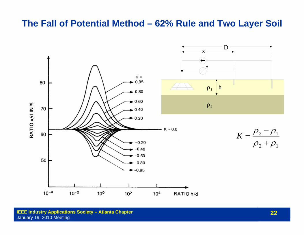
The Fall of Potential Method – 62% Rule and Two Layer Soil
D x
h ρ1
ρ2
12
12
ρρρρ
+−
=K
IEEE Industry Applications Society – Atlanta ChapterJanuary 19, 2010 Meeting
23
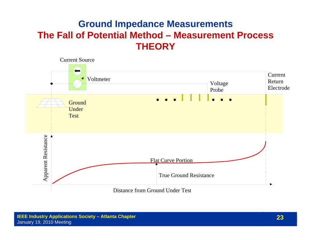
Ground Impedance MeasurementsThe Fall of Potential Method – Measurement Process
THEORY
Flat Curve Portion
CurrentReturnElectrode
Current Source
VoltmeterVoltageProbe
App
aren
t Res
ista
nce
GroundUnderTest
True Ground Resistance
Distance from Ground Under Test
IEEE Industry Applications Society – Atlanta ChapterJanuary 19, 2010 Meeting
24
0
0.2
0.4
0.6
0.8
1
1.2
1.4
0 500 1000 1500 2000 2500Distance (feet)
Res
ista
nce
(Ohm
s)
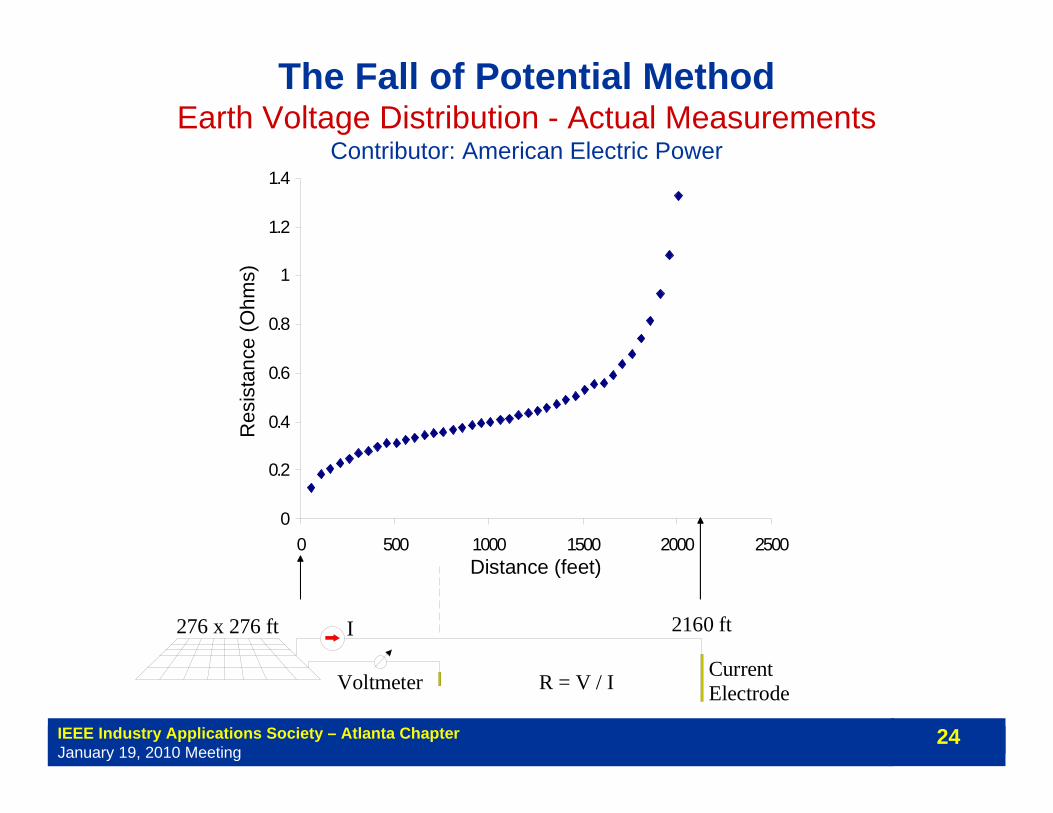
The Fall of Potential MethodEarth Voltage Distribution - Actual Measurements
Contributor: American Electric Power
276 x 276 ft 2160 ft
CurrentElectrodeVoltmeter
I
R = V / I
IEEE Industry Applications Society – Atlanta ChapterJanuary 19, 2010 Meeting
25
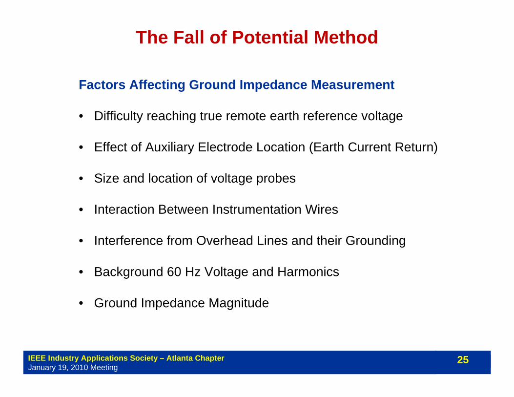
Factors Affecting Ground Impedance Measurement
• Difficulty reaching true remote earth reference voltage
• Effect of Auxiliary Electrode Location (Earth Current Return)
• Size and location of voltage probes
• Interaction Between Instrumentation Wires
• Interference from Overhead Lines and their Grounding
• Background 60 Hz Voltage and Harmonics
• Ground Impedance Magnitude
The Fall of Potential Method
IEEE Industry Applications Society – Atlanta ChapterJanuary 19, 2010 Meeting
26
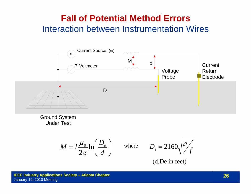
Fall of Potential Method ErrorsInteraction between Instrumentation Wires
⎟⎠⎞
⎜⎝⎛=
dDlM eln
20
πμ
fDeρ2160=
(d,De in feet)
where
CurrentReturnElectrode
VoltageProbe
Ground SystemUnder Test
M
Current Source I(ω)
Voltmeter d
D
IEEE Industry Applications Society – Atlanta ChapterJanuary 19, 2010 Meeting
27
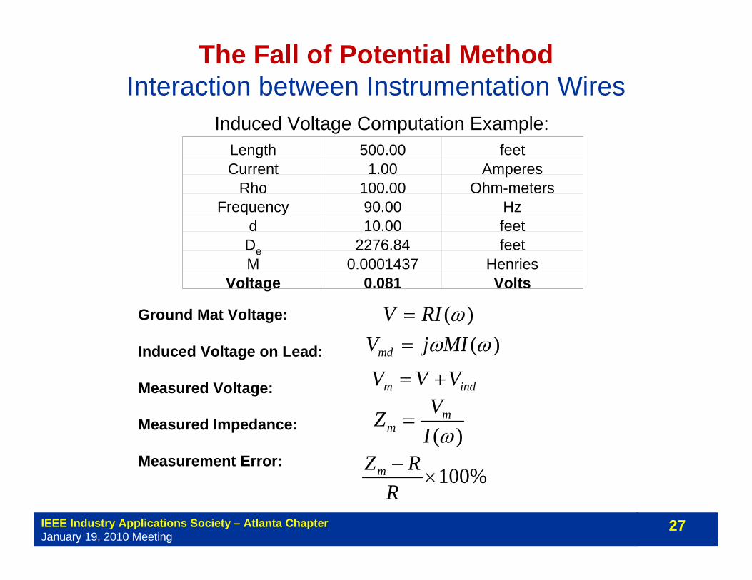
Induced Voltage Computation Example:Length 500.00 feetCurrent 1.00 Amperes
Rho 100.00 Ohm-metersFrequency 90.00 Hz
d 10.00 feetDe 2276.84 feetM 0.0001437 Henries
Voltage 0.081 Volts
Ground Mat Voltage:
Induced Voltage on Lead:
Measured Voltage:
Measured Impedance:
Measurement Error:
)(ωRIV =)(ωωMIjVmd =
indm VVV +=
)(ωIVZ m
m =
%100×−
RRZm
The Fall of Potential MethodInteraction between Instrumentation Wires
IEEE Industry Applications Society – Atlanta ChapterJanuary 19, 2010 Meeting
28
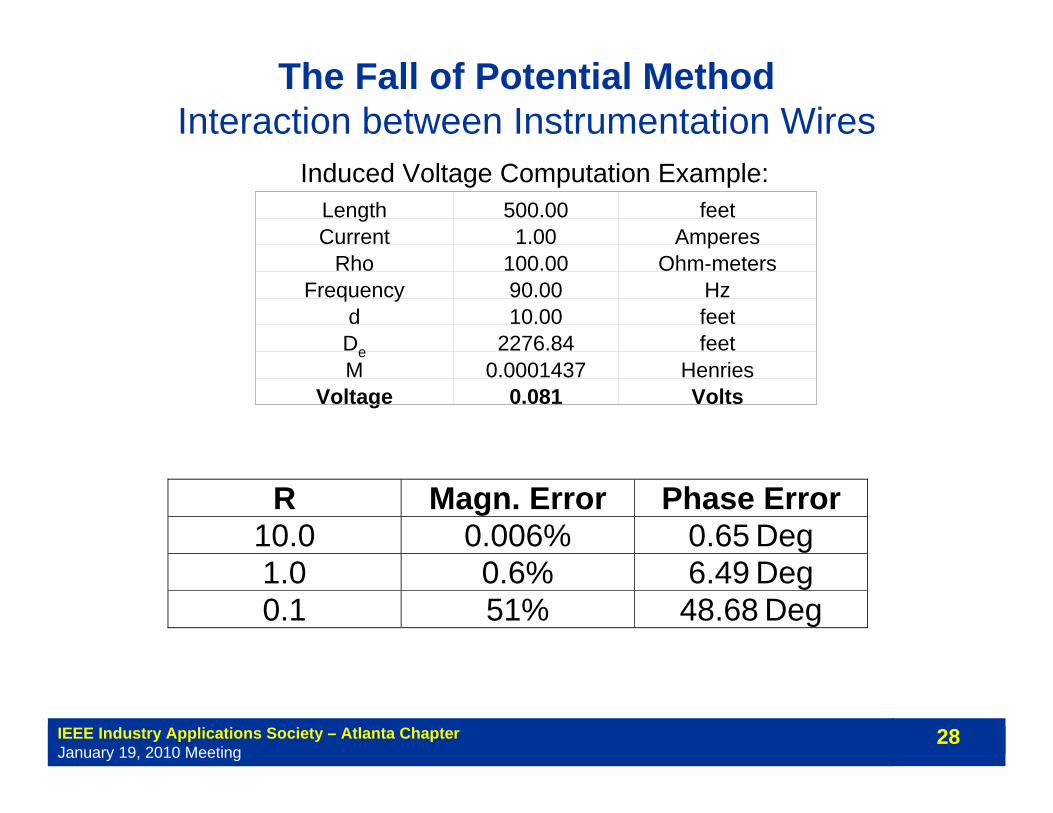
Induced Voltage Computation Example:Length 500.00 feetCurrent 1.00 Amperes
Rho 100.00 Ohm-metersFrequency 90.00 Hz
d 10.00 feetDe 2276.84 feetM 0.0001437 Henries
Voltage 0.081 Volts
The Fall of Potential MethodInteraction between Instrumentation Wires
R Magn. Error Phase Error 10.0 0.006% 0.65 Deg 1.0 0.6% 6.49 Deg 0.1 51% 48.68 Deg
IEEE Industry Applications Society – Atlanta ChapterJanuary 19, 2010 Meeting
29
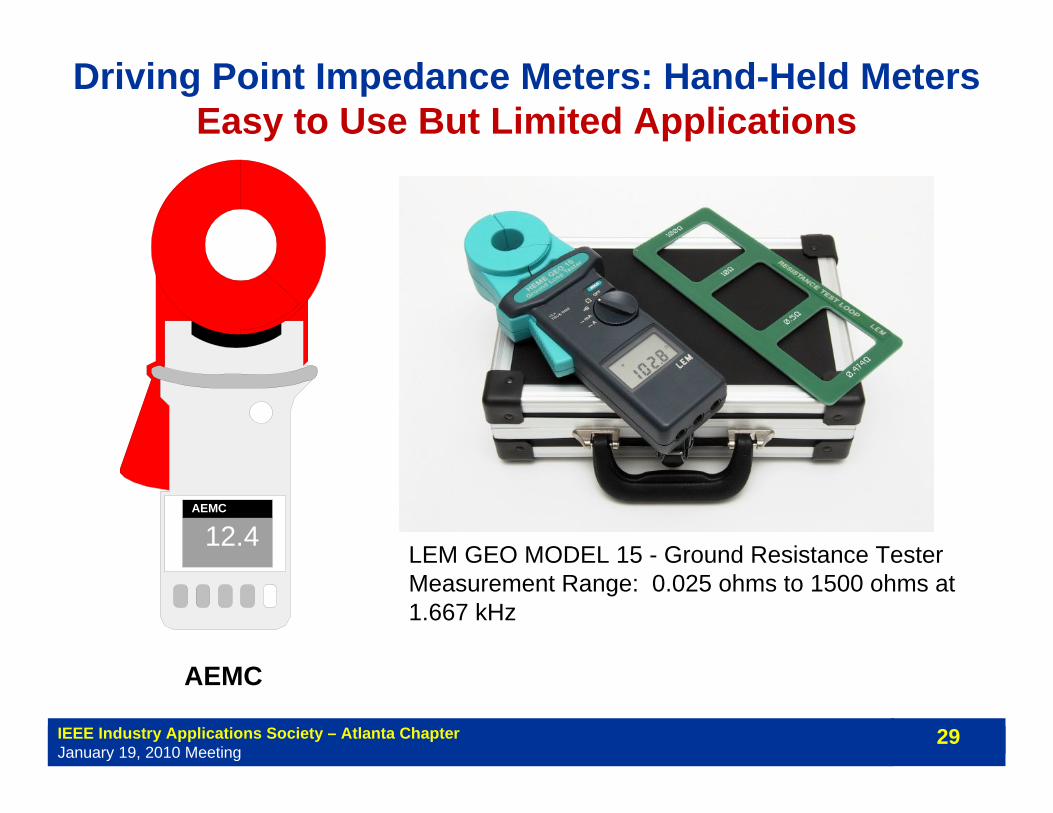
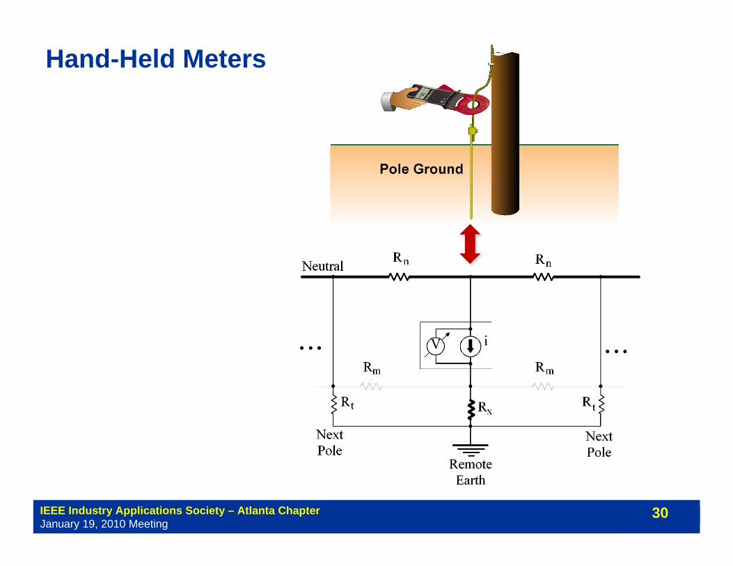
Driving Point Impedance Meters: Hand-Held MetersEasy to Use But Limited Applications
LEM GEO MODEL 15 - Ground Resistance TesterMeasurement Range: 0.025 ohms to 1500 ohms at 1.667 kHz
12.4AEMC
AEMC
IEEE Industry Applications Society – Atlanta ChapterJanuary 19, 2010 Meeting
30
Hand-Held Meters
IEEE Industry Applications Society – Atlanta ChapterJanuary 19, 2010 Meeting
31
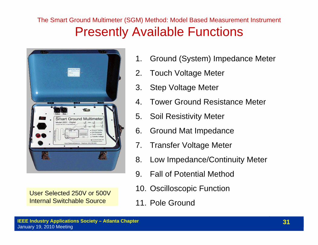
The Smart Ground Multimeter (SGM) Method: Model Based Measurement Instrument
Presently Available Functions
1. Ground (System) Impedance Meter
2. Touch Voltage Meter
3. Step Voltage Meter
4. Tower Ground Resistance Meter
5. Soil Resistivity Meter
6. Ground Mat Impedance
7. Transfer Voltage Meter
8. Low Impedance/Continuity Meter
9. Fall of Potential Method
10. Oscilloscopic Function
11. Pole GroundUser Selected 250V or 500V Internal Switchable Source
IEEE Industry Applications Society – Atlanta ChapterJanuary 19, 2010 Meeting
32
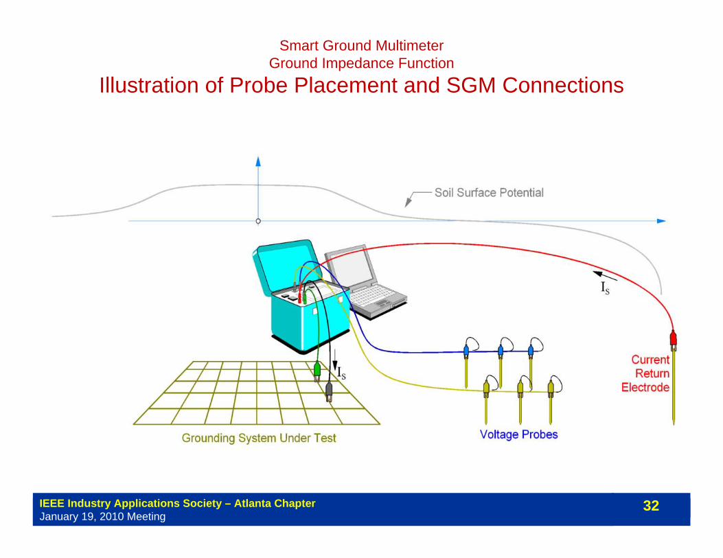
Smart Ground MultimeterGround Impedance Function
Illustration of Probe Placement and SGM Connections

IEEE Industry Applications Society – Atlanta ChapterJanuary 19, 2010 Meeting
33
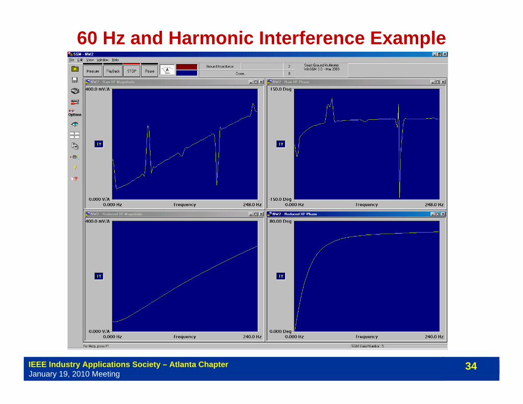
60 Hz and Harmonic Interference Correction
Raw Transfer Function
Interference Corrected Transfer Function
Frequency
Tran
sfer
Fun
ctio
n M
agni
tude
Correction Method: Based on quadratic rational transfer function fitting
( )∑ −k
kkk jHjHW2
)()(ˆ ωω
where:2
210
2210)(ˆsbsbbsasaasH
++++
=or 2210)(ˆ sasaasH ++=
Minimize:
IEEE Industry Applications Society – Atlanta ChapterJanuary 19, 2010 Meeting
34
60 Hz and Harmonic Interference Example
IEEE Industry Applications Society – Atlanta ChapterJanuary 19, 2010 Meeting
35
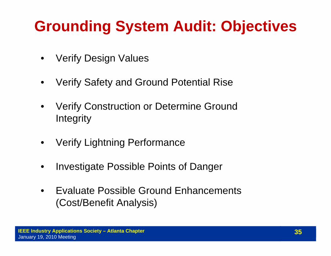
Grounding System Audit: Objectives
• Verify Design Values
• Verify Safety and Ground Potential Rise
• Verify Construction or Determine Ground Integrity
• Verify Lightning Performance
• Investigate Possible Points of Danger
• Evaluate Possible Ground Enhancements (Cost/Benefit Analysis)
IEEE Industry Applications Society – Atlanta ChapterJanuary 19, 2010 Meeting
36
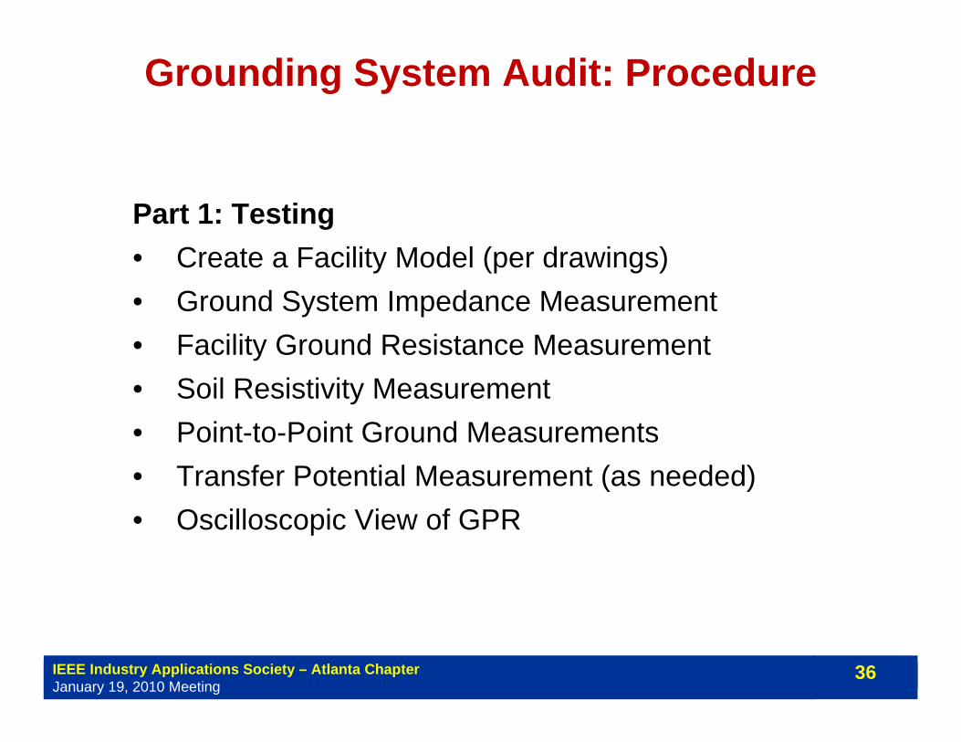
Grounding System Audit: Procedure
Part 1: Testing• Create a Facility Model (per drawings)• Ground System Impedance Measurement• Facility Ground Resistance Measurement• Soil Resistivity Measurement• Point-to-Point Ground Measurements • Transfer Potential Measurement (as needed)• Oscilloscopic View of GPR

IEEE Industry Applications Society – Atlanta ChapterJanuary 19, 2010 Meeting
37
Grounding System Audit: Procedure
Part 2: Model Validation and Analysis• Ground Model Validation (Compare Model to
Measurements)• Ground Conductor Size Adequacy Assessment• Safety Assessment (IEEE Std 80 or IEC)• Lightning Shielding Analysis and Risk Evaluation• Evaluation of Remedial Measures (as needed)

IEEE Industry Applications Society – Atlanta ChapterJanuary 19, 2010 Meeting
38
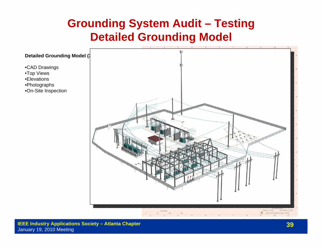
Grounding System Audit – TestingDetailed Grounding Model
Detailed Grounding Model (3D)
•CAD Drawings•Top Views•Elevations•Photographs•On-Site Inspection
1
1
2
2
3
3
4
4
5
5
6
6
7
7
8
8
9
9
10
10
11
11
A A
B B
C C
D D
E E
F F
G G
H H
I I
J J
K K
L L
Advanced Grounding Concepts / WinIGS
February 17, 2002 AGC-APHA-2-17-2002Grounding System
ALPHA
Scale (feet)0' 50' 100' 150'
N
BUS161-2_NMAIN-GND
FENCE_NFENCE
X
YGrid Spacing: 500.0 ftModel B
IEEE Industry Applications Society – Atlanta ChapterJanuary 19, 2010 Meeting
39
Grounding System Audit – TestingDetailed Grounding Model
Detailed Grounding Model (3D)
•CAD Drawings•Top Views•Elevations•Photographs•On-Site Inspection
1
1
2
2
3
3
4
4
5
5
6
6
7
7
8
8
9
9
10
10
11
11
A A
B B
C C
D D
E E
F F
G G
H H
I I
J J
K K
L L
Advanced Grounding Concepts / WinIGS
February 17, 2002 AGC-APHA-2-17-2002Grounding System
ALPHA
Scale (feet)0' 50' 100' 150'
N
BUS161-2_NMAIN-GND
FENCE_NFENCE
X
YGrid Spacing: 500.0 ftModel B
IEEE Industry Applications Society – Atlanta ChapterJanuary 19, 2010 Meeting
40
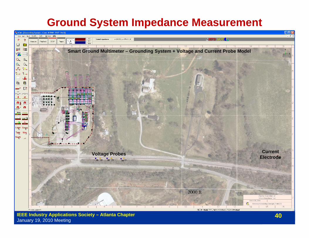
Ground System Impedance Measurement
Smart Ground Multimeter – Grounding System + Voltage and Current Probe Model
Voltage Probes Current Electrode
IEEE Industry Applications Society – Atlanta ChapterJanuary 19, 2010 Meeting
41
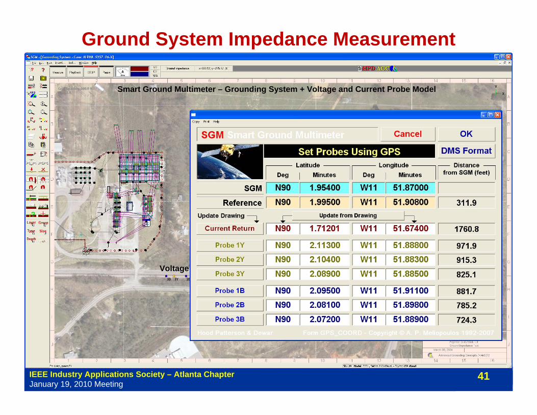
Ground System Impedance Measurement
Smart Ground Multimeter – Grounding System + Voltage and Current Probe Model
Voltage Probes Current Electrode

IEEE Industry Applications Society – Atlanta ChapterJanuary 19, 2010 Meeting
42
Grounding System Audit – TestingSoil Resistivity Measurement
• Uses estimation based analysis to fit the measurements to the measurement system model
• Provides Measurement Interpretation (Two Layer Model)
Smart Ground Multimeter•Based on extension of the four pin method
•Measures ground potential differences between six voltage

IEEE Industry Applications Society – Atlanta ChapterJanuary 19, 2010 Meeting
43
Soil Resistivity Measurement

IEEE Industry Applications Society – Atlanta ChapterJanuary 19, 2010 Meeting
44
Soil Resistivity Measurement
IEEE Industry Applications Society – Atlanta ChapterJanuary 19, 2010 Meeting
45
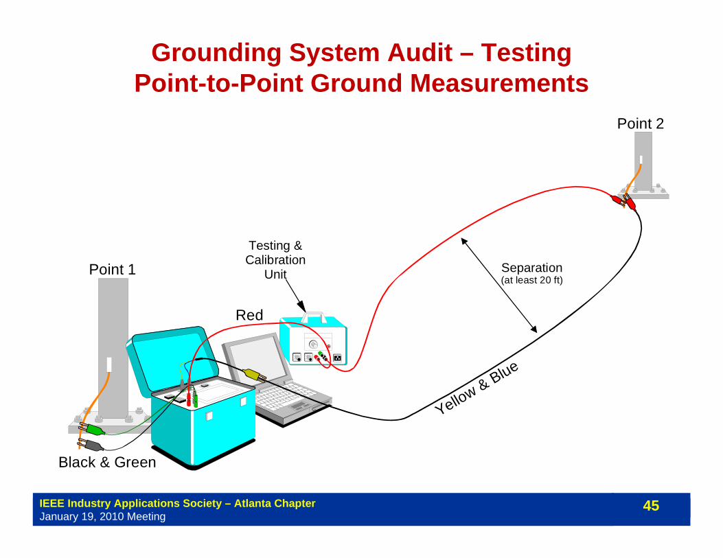
Grounding System Audit – TestingPoint-to-Point Ground Measurements
Testing &Calibration
Unit Separation(at least 20 ft)
Point 1
Point 2
Red
Black & Green
Yellow & Blue

IEEE Industry Applications Society – Atlanta ChapterJanuary 19, 2010 Meeting
46
Grounding System Audit – TestingPoint-to-Point Ground Measurements
Testing &Calibration
Unit Separation(at least 20 ft)
Point 1
Point 2
Red
Black & Green
Yellow & Blue


