Proceedings of the International Conference on Emerging Trends in Engineering and Management
(ICETEM14) 30-31,December, 2014, Ernakulam, India
121
TENSILE AND MICROSTRUCTURAL
CHARACTERESTICS OF DCSP TIG WELDED AND
FRICTION STIR WELDED AA2219 ALUMINIUM ALLOY
BAIJU SASIDHARAN, Dr.K.P.NARAYANAN, PRAKASH.R.S
1Dept. of Mechanical Engineering, College of Engineering Trivandrum,Thiruvanantapuram, 695 016, Kerala , India
2Dept. of Ship Technology, CUSAT, Cochin 682 022, Kerala, India
3Indian Institute of Space Science and Technology, Valiyamala, Thiruvananthpuram,Kerala , India
ABSTRACT
Weld strength and microstructure differs for the same material depending up on the welding process and
techniques used. This paper lights on that aspects in the case of high strength low weight aluminium alloy AA2219,
which possess low thermal characteristics. Welded joints from two types of welding techniques namely DCSP (Direct
current straight polarity) TIG welding and Friction Stir Welding (FSW) have been considered for the present study.
These two welding techniques are characterized by their low heat input to the metal while joining. In DCSP TIG
welding weld plate and electrodes are connected positive and negative leads of weld transformer respectively with a
constant supply of current. Due to the hitting of more number of electrons from electrode on job while welding, joining
edges were heated with less heat input which result in a welded joint with good weld strength. FSW is a solid metal
joining process where no melting of material is taking place compared to conventional welding techniques. Here a FSW
set up has been developed in a conventional vertical milling machine (with a tool geometry of 20mm shoulder diameter,
6.35mm as pin diameter and 5mm as pin length, tool rotation of 1800 rpm, linear traverse of 100mm/min) and obtained
good FSW joints. Comparative study on Tensile and Micro structural characteristics of welded joints obtained from
DCSP TIGW and FSW has been made. The Ultimate Tensile Strength (UTS) of DCSP TIG welded joint has been found
257.48MPa. The UTS for FSW resulted is 287.9MPa. They are 58.5% and 65.4% compared to the parent metal.
Percentage elongation for FSW joint has also been found more than that of parent metal. From the microstructure study
it is seen that FSW joints are having very less micro porosities compared to DCSP TIG welded joints. Hence it is inferred
that FSW techniques are more suited for the effective joining of alloys like AA2219.
Keywords: AA2219 Aluminium Alloy, DCSP TIG welding, Friction Stir Welding set up, Tensile and Microstructure
characteristics
I. INTRODUCTION
Gas Tungsten Arc Welding (GTAW), also known as Tungsten Inert Gas (TIG) [24] welding is a process that
produces an electric arc maintained between a non-consumable tungsten electrode and the part to be welded. The heat-
affected zone, the molten metal and the tungsten electrode are all shielded from atmospheric contamination by a blanket
of inert gas fed through the GTAW torch. It is mainly used for the joining of aluminium Alloys and dissimailar welding
of metal combination like brass and copper. In TIGW process two versions of DC power source can be used to weld
Aluminum Alloys. One is Direct Current Straight Polarity (DCSP) TIGW and the other is Direct current reverse polarity
(DCRP) TIGW. In DCSP TIGW , the electrons flow is from the electrode to the plate, concentrating most of the heat on
INTERNATIONAL JOURNAL OF DESIGN AND MANUFACTURING TECHNOLOGY (IJDMT)
ISSN 0976 – 6995 (Print)
ISSN 0976 – 7002 (Online)
Volume 5, Issue 3, September - December (2014), pp. 121-129
© IAEME: http://www.iaeme.com/IJDMT.asp
Journal Impact Factor (2014): 4.9284 (Calculated by GISI)
www.jifactor.com
IJDMT
© I A E M E

Proceedings of the International Conference on Emerging Trends in Engineering and Management
(ICETEM14) 30-31,December, 2014, Ernakulam, India
122
the work, reverse in the case of DCRP TIGW. DCSP enablesthe melting of job with less heat input and better weld
strength. Fig. 1 shows schematic diagram of TIG welding [2].
Friction Stir welding is a solid welding technique. It was invented at the welding institute (TWI) of the United
Kingdom in 1991 as a solid state joining technique and was initially applied to aluminium alloy [3]. The basic concept of
FSW is remarkably simple. A non consumable protecting tool with a specially designed pin and shoulder is inserted in to
the butting edges of sheets or plate to be joined and subsequently traversed along the joint line. The weld is formed by
the excessive deformation of the material at temperatures below its melting point. There is no melting of the material, so
FSW has several advantages over the commonly used fusion welding techniques. For example, there are no porosity or
cracking in the weld region, there is no significant distortion of the work pieces (particularly in thin plates), and there is
no need for filler materials, shielding gases and costly weld preparation during this joining process. FSW is considered to
be the most remarkable and potentially useful welding technique for several materials, such as Al-alloys, Mg-alloys
brasses, Ti-alloys, and steels. Fig. 2 shows the schematic representation of FSW. The main process parameters of FSW
techniques are Geometry of the tool, Tool-material, Tool traversing speed, Rotation of the spindle, Orientation of
spindle, Axial loading on the tool, Tool tilt angle, position of the tool(Advancing or retreating side), Tool heat input,
Cooling rate, Thickness of the plates to be welded, Material of the weld specimen etc.
Fig.2 Fiction Stir Welding [2]
FSW is considered to be the most significant development in metal joining in decades. In addition, it is a green
technology due to its energy efficient, environmental friendliness and versatility. As compared with the conventional
welding method FSW consumes less energy no consumable such as cover gas or flux are used and no harmful emission
are created during welding, thereby making process environmental friendly. FSW can be used to improve microstructure
and to improve the surface properties of metals. It has the potential for joining similar and dissimilar materials that
cannot be welded by conventional welding processes. Since no melting of materials is involved in friction stir welding it
can avoids the weaknesses caused by distortion and metallurgical reactions in conventional welding [4].
AA2219 is an Aluminium copper alloy developed by Aluminium Company of America (ALCOA) in 1954 for
applications at temperatures up to 315 0C. This heat treatable alloy also possesses good cryogenic properties. For this
reason this alloy is nick named as “wonder alloy”.AA2219 is basically Al-Cu-Mn turnery alloy with minor additions of
Ti, V and Zr. It is the most widely and successfully used cryo aluminium alloy and flown in various launch vehicles. The
excellent strength and toughness at cryo temperatures coupled with excellent weldability make this alloy an obvious
choice for fabrication of cryo tanks. AA2219 can withstand weld shrinkage strains up to 12% compared to normally
encountered weld strains of the order of 4%. This implies that the probability of occurrence of cracks in this material
during welding is minimal compared to other Al alloys. Table 1 shows the chemical composition of AA2219. Different
mechanical characteristics of AA2219 alloy are given in Table 2
As AA2219 Alloy has huge applications in Aerospace Industry. A number of research papers are available
based on its various advantages. R.K Gupta and SVS Narayana Murty [5] have conducted analysis of crack in AA2219
TIG welded joints. They found that even though this alloy is not prone to liquation/ solidification cracking it can crack
under certain conditions acting together like improper fixturing, large heat input, large grain size of the materials etc.
S.R.Koteswara Rao, G.Madhusudhan Reddy and K Prasad Rao [6] have conducted studies to understand the effect on
thermo mechanical treatments on mechanical properties of AA2219 GTA welds. They found that compressive
deformation of fusion zone in AA2219 GTA weldments caused for better hardness. S. Malarvizhi and V
Balasubramanian [7] conducted studies to understand the effect of post weld ageing treatments on the fatigue behaviour

Proceedings of the International Conference on Emerging Trends in Engineering and Management
(ICETEM14) 30-31,December, 2014, Ernakulam, India
123
of Friction stir welded (FSW) AA2219 Aluminum Alloys. Li.J and Liu.H [8] have conducted studies to find the
improvement in Mechanical and Microstructure properties of FSW joint from AA2219, by the reverse dual rotation of
FSW tool. Jin-kun DING, Dong-po WANG, Ying WANG, HuiDU [9] also found that the mechanical characteristics of
TIG welded joints from AA 2219 have improved with post weld heat treatments. Ch.V.A. Narasayya, P. Rambabu,
M.K.Mohan, Rahul Mitra and Eswara Prasad [10] have conducted studies on tensile deformation and Fracture behavior
of AA2219 in different ageing conditions. They found that no much variations has been observed in the microstructure
under different ageing conditions
Y.M. Hwang, P L Fan and C H Lin [11] have conducted experiments in FSW of copper metals (C11000). The
study mainly aimed to explore the thermal history of work piece during FSW. They have also conducted tensile
characteristic study of FSW joints. D.Trimble, J Monaghan and GE O Donell [12] have done experiments to monitor the
force generation during Friction Stir Welding of AA 2024-T3 plates. Pasquale Cavaliere [13] have conducted
experiments to evaluate the fatigue life and crack behavior of several Friction Stir Welded Aluminium Alloys. H.Su, C S
Wu and A Pittner et.al 2013 [14] done experiment on FSW to facilitate simultaneous measurement of tool torque,
traverse force and axial forces. Different from traditional measurements methods using load cell or rotating compound
dynamometer has been utilised for the work. Yu E Ma, Z C Xia R.R.Jiang et.al [15] have done experiments to study
the effect of welding process parameters on mechanical and fatigue properties of friction welded 2198 T8 Aluminium –
Lithium Alloy joints. Jau-Wen Lin, His- Cherng Chang and Ming-Hsiu Wn [16] have done experiments on FSW
process to compare the mechanical and microstructure properties of pure copper welded using FSW and TIGW.
RMF Paulo, P Carlone and RAF.Valente et.al [17] has done experiment to study the influence of friction
welding residual stress on compressive strength of aluminium plates. G.D.Urso ,C.Giardini and S.Lorenzi (2014) [18]
have done experiment to study the fatigue crack growth in the welding nugget of FSW joints of 6060 aluminium alloy.
Tensile tests, metallographic analyses and micro Vickers tests were also carried out to evaluate the mechanical properties
of the joints as a function of process parameters Tracie Prater (2014) [19] has done experiments on friction stir welding
of composites for use in Aerospace structures. According to him FSW was now used to join structural components of the
Delta IV, Atlas V, and Falcon IX rockets as well as the Orion Crew exploration vehicles. Also he described that current
research on FSW is the joining of newly developed composite material to be used in Aerospace structures, which are
very difficult to weld by conventional methods.
Table-1 Chemical Composition of AA2219
Element Cu Mn Zr V Ti Fe Si Zn Mg Other impurites Al
Minimum 5.8 0.2 0.1 0.05 0.02 - - - - - -
Maximum 6.8 0.4 0.25 0.02 0.1 0.3 0.2 0.1 0.1 0.15 Reminder
Table.2 Mechanical Charrecterestics of AA2219
Density Poissons
ratio
Elastic
Modulus
Ultimate
Tensile
Strength
0.2% Yield
Strength
Percentage
Elongation
Fatigue
Strength
Thermal
Conductivity
Kg/m3 - GPa MPa MPa - MPa W/m-K
2.6-2.8
x 100 0.33 70-80 440 350 6 105 170
II. EXPERIMENTAL INVESTIGATIONS
The different stages in the experimental investigations included planning the set ups of each welding process
and preparation of material AA 2219, Formation of welded joints, weld inspection and investigation on mechanical and
metallurgical characteristics. Different weld trials and weld characterization were made to arrive optimized weld
parameters. Thus three weld coupons per process based on optimized weld parameters have been produced.
2.1. Execution of DCSP TIG welding process DCSP TIG welding process has been carried out using the TIG welding unit and the fixture fabricated, as
shown in Fig.2. The American welding society (AWS) recommended filler wire for TIGW of AA2219 is ER2319 (E-for
electrode and R-for rod). The chemical composition of ER2319 is same as that of AA2219 except higher titanium content
(0.1 - 0.2%). Higher titanium content ensures finer and uniform grain size in solidified weldment. Table.3 shows DCSP
welding process parameters considered.
Proceedings of the International Conference on Emerging Trends in Engineering and Management
(ICETEM14) 30-31,December, 2014, Ernakulam, India
124
Table. 3DCSP welding process details
Name of welding
Machine
Material used
and size
Name of filler
material used
Current and
Voltage
Shielding
gas
Travel
speed Back up bar
Miller make AA2219,
300 X 300 mm ER2319 220Amp, 20V Helium
100
mm/min Stainless steel
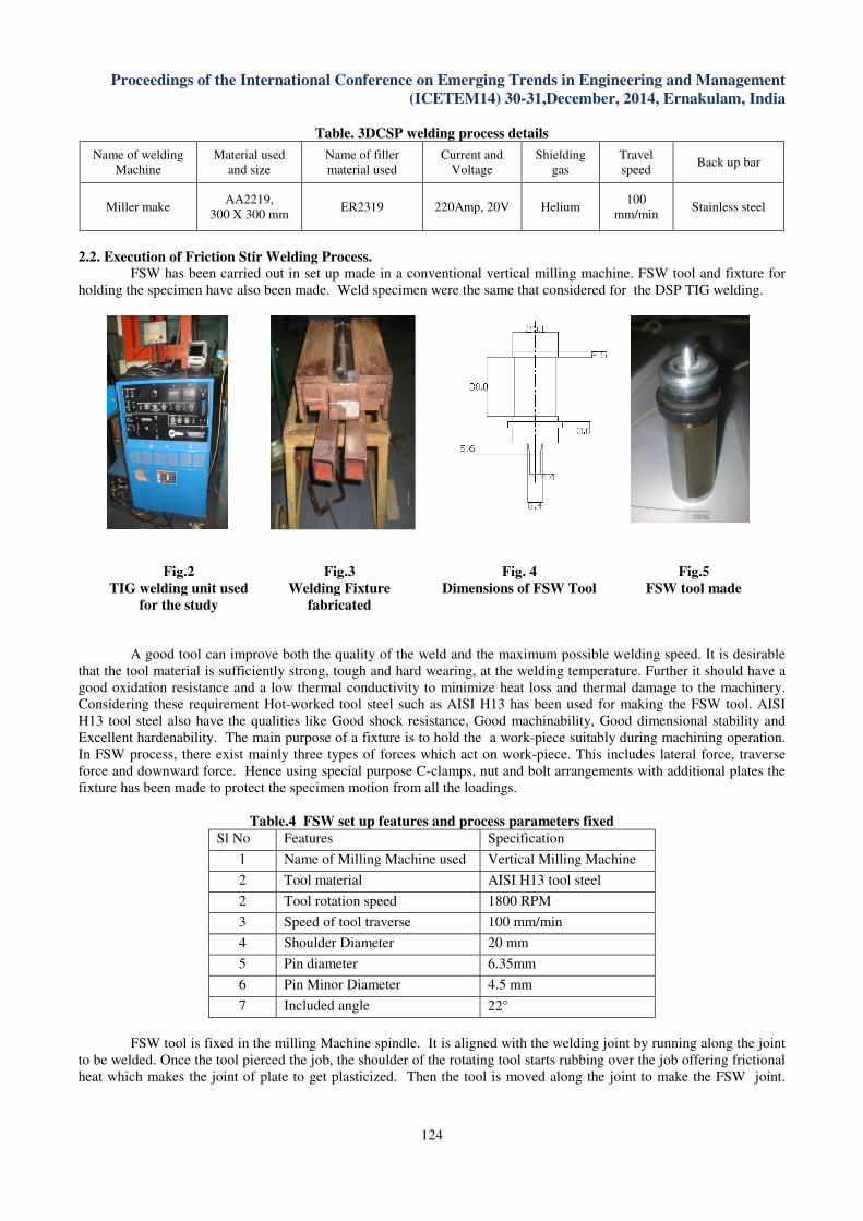
2.2. Execution of Friction Stir Welding Process.
FSW has been carried out in set up made in a conventional vertical milling machine. FSW tool and fixture for
holding the specimen have also been made. Weld specimen were the same that considered for the DSP TIG welding.
Fig.2
TIG welding unit used
for the study
Fig.3
Welding Fixture
fabricated
Fig. 4
Dimensions of FSW Tool
Fig.5
FSW tool made
A good tool can improve both the quality of the weld and the maximum possible welding speed. It is desirable
that the tool material is sufficiently strong, tough and hard wearing, at the welding temperature. Further it should have a
good oxidation resistance and a low thermal conductivity to minimize heat loss and thermal damage to the machinery.
Considering these requirement Hot-worked tool steel such as AISI H13 has been used for making the FSW tool. AISI
H13 tool steel also have the qualities like Good shock resistance, Good machinability, Good dimensional stability and
Excellent hardenability. The main purpose of a fixture is to hold the a work-piece suitably during machining operation.
In FSW process, there exist mainly three types of forces which act on work-piece. This includes lateral force, traverse
force and downward force. Hence using special purpose C-clamps, nut and bolt arrangements with additional plates the
fixture has been made to protect the specimen motion from all the loadings.
Table.4 FSW set up features and process parameters fixed
Sl No
Sl No
Features Specification
1 Name of Milling Machine used Vertical Milling Machine
with digital readout 2 Tool material AISI H13 tool steel
2 Tool rotation speed 1800 RPM
3 Speed of tool traverse 100 mm/min
4 Shoulder Diameter 20 mm
5 Pin diameter 6.35mm
6 Pin Minor Diameter 4.5 mm
7 Included angle 22°
FSW tool is fixed in the milling Machine spindle. It is aligned with the welding joint by running along the joint
to be welded. Once the tool pierced the job, the shoulder of the rotating tool starts rubbing over the job offering frictional
heat which makes the joint of plate to get plasticized. Then the tool is moved along the joint to make the FSW joint.

Proceedings of the International Conference on Emerging Trends in Engineering and Management
(ICETEM14) 30-31,December, 2014, Ernakulam, India
125
Different weld trials were done to get the optimized weld parameters. Thus two FSW weld coupons were produced with
optimized weld parameters. Table 4 shows the features of the FSW set up made.
Fig 6. FSW set up showing FSW tool , AA 2019 plates and the fixtures made
Fig. 7FSWweldment300 x 300 mm
Test coupon-Top bead side
Fig. 8FSW Weldment300 x 300 mm
Test coupon- Root Bead Root Bead
2.3. Tensile characterization tests
Three tensile test specimens from each weld coupon have been prepared as per ASTM E8 standard[21] as
shown in Fig 7. The specimens were cut and prepared using wire cut EDM machine and milling machine.
Fig.9Tensile test specimen as per ASTME8 standard
2.4 . Microstructure examination:
The micro structure specimen, 20× 10× 5 mm, have been cut transversely to the welding direction. They then
cold mounted and wet grounded using finer grades of SiC impregnated emery papers. Polishing has been done using 6, 3
and finally 1 µm diamond paste as the lubricant on polishing cloths. Macroscopic examination have been carried out by
etching the specimen using a caustic etch (i.e. 10g NaOH in 90 ml H2O with 50% HNO3 solution and a final rinse in
water.) Microscopic examination was done by using Keller’s reagent. The microstructure has been observed under
Olympus optical microscope [22].

Proceedings of the International Conference on Emerging Trends in Engineering and Management
(ICETEM14) 30-31,December, 2014, Ernakulam, India
126
III. RESULTS AND DISCUSSIONS
The results from tensile and Microstructure characteristic of DCSP TIG Welded and Friction Stir Welded joints
are discussed in the following sessions.
3.1Results from Tensile tests
The results from tensile characteristic studies for DCSP welded joints are presented in Table 5. For FSW joints
it is presented in Table 6.
Table.5 Achieved Mechanical Properties –DCSP TIG welded joints
DCSP TIG welded joint Area
Ultimate
Load
Gauge
Length
Ultimate
Tensile
Strength
0.2%Yield
strength % Elongation
mm2 kN mm Mpa MPa
Weld Coupon No:1
49.6 12.9 50 260 156 5.08
51.1 12.8 50 250 158 5.12
50.3 12.8 50 254 156 5
Weld Coupon No:2
44.9 12 50 258 158 6.02
47.8 11.9 50 249 163 5.68
47.5 12.1 50 255 157 5.7
Weld Coupon No:3
46.4 12.2 50 262 144 5.68
46.4 12.2 50 263 142 5.54
46.6 12 50 257 143 5.44
Table.6 Achieved Mechanical Properties –FSW joints
FSW joints Area
Ultimate
Load
Gauge
Length
Ultimate
Tensile
Strength
0.2%Yield
strength % Elongation
mm2 kN mm Mpa MPa
Weld Coupon No:1
58.18 17.05 50 293.00 170 8.8
57.87 16.82 50 290.65 165 8.3
58.49 16.88 50 288.6 167 8.13
Weld Coupon No:2
59.03 16.93 50 286.61 166 8.04
58.71 16.68 50 285.5 170 8.8
58.54 16.60 50 283.11 163 8.52
Weld Coupon No:3
58.2 17.04 50 287 168 8.5
58.5 17.8 50 288.2 165 8.3
58.7 16.7 50 288 168 8.4
The average value of UTS for DCSP TIG welded joint is 257 MPa. It is 58.5 % compared to the parent metal.
Yield strength (0.2% YS ) for the same is 153 MPa which is 58.5% compared to the parent metal. Percentage elongation
was also found 5.47 It is comparatively close to the value of parent metal. However the values were found less
comparing the result obtained for FSW joints.
Table. 7 Average Tensile test results for DCSP and FSW joints
Type of welded joint UTS (MPa) Yield Strength (MPa) % Elongation
DCSP TIG Weld 257 153 5.47
FSW joints 287.9 166.8 8.4
In the case of FSW joint the value of UTS is 287.9 MPa. When compared to parent metal it is near to 65.4%.
The 0.2% YS values forthe same is 166.8 MPa, which is 47.6 % compared to parent metal. Percentage elongation of
FSW joint is 8.4. It is higher than that of parent metalFig 10. shows the graphical representation of the percentage
variation of results for welded joints. Fig. 11 represents the histogram for the percentage elongation.

Proceedings of the International Conference on Emerging Trends in Engineering and Management
Fig. 10 Percentage variation of UTS and
Yield strength.
3.2 Micro structural Analysis:
The microstructure of weld cross section was examined at 100 X and photographed using Olympus o
microscopy. Different regions such as weld zone, interface
parent metal were examined. The details of microstructure
boundaries are given below.
A close look at the micro structural and micro constituent phases of the samples would give more insight into
the variations in the mechanical properties of AA 2219 alloy fabricated using
Welding. Optical microstructure of the sample for DCSP process revealed for isolated micro porosities. Discontinuous
Cu rich film was also observed along the grain boundaries in the HAZ region. Fine, elongated grains was observed in the
parent material region. Second phase particles of (Fe,Mn)
the parent material. All these values are attributed to the suitability of DCSP for the welding of AA2219 alloy.
comparing to the result obtained for FSW join
comparatively better than conventional welding techniques.
The microstructure photographs of DCSP (Fig 11 to 13), welded specimens are given below.
Fig 12 DCSP Weld parent metal
International Conference on Emerging Trends in Engineering and Management
(ICETEM14) 30-31,December, 2014, Ernakulam, India
127
Fig. 10 Percentage variation of UTS and
Fig. 11 Percentage elongation
The microstructure of weld cross section was examined at 100 X and photographed using Olympus o
microscopy. Different regions such as weld zone, interface - partially melted zone (PMZ), heat affected zone (HAZ) and
were examined. The details of microstructure [23] along with observation of gas porosities and grain
A close look at the micro structural and micro constituent phases of the samples would give more insight into
the variations in the mechanical properties of AA 2219 alloy fabricated using DCSP TIG welding
al microstructure of the sample for DCSP process revealed for isolated micro porosities. Discontinuous
observed along the grain boundaries in the HAZ region. Fine, elongated grains was observed in the
hase particles of (Fe,Mn)3, SiAl2 and coarse CuAl2 were also observed in the matrix of
All these values are attributed to the suitability of DCSP for the welding of AA2219 alloy.
comparing to the result obtained for FSW joints it can be seen that for the joining of aluminium alloys FSW is
comparatively better than conventional welding techniques.
photographs of DCSP (Fig 11 to 13), welded specimens are given below.
rent metal Fig 13 DCSP weld Zone:
International Conference on Emerging Trends in Engineering and Management
31,December, 2014, Ernakulam, India
Fig. 11 Percentage elongation
The microstructure of weld cross section was examined at 100 X and photographed using Olympus optical
partially melted zone (PMZ), heat affected zone (HAZ) and
along with observation of gas porosities and grain
A close look at the micro structural and micro constituent phases of the samples would give more insight into
DCSP TIG welding and FSW riction Stir
al microstructure of the sample for DCSP process revealed for isolated micro porosities. Discontinuous
observed along the grain boundaries in the HAZ region. Fine, elongated grains was observed in the
were also observed in the matrix of
All these values are attributed to the suitability of DCSP for the welding of AA2219 alloy. However
ts it can be seen that for the joining of aluminium alloys FSW is
Fig 13 DCSP weld Zone:

Proceedings of the International Conference on Emerging Trends in Engineering and Management
Fig 14 DCSP Interface Zone:
Fig 16 DCSP weld Zone
Samples made from the friction stir welding
and inter dentritic porosities were absent in the samples. No interface between the HAZ and weld regions was observed.
Cu rich films along the grain boundaries were absent in the HAZ region. Flow of grains in the direction of tool
movement was observed. The highest mechanical properties including elongation of more than 8% in the FSW samples
could be attributed to the absence of micro porosities and brittle Cu rich films in the samples.
IV. CONCLUSION
AA 2219 plates were successfully welded using
257.48MPa and 287.9for the joints by DCSP TIGW and FSW.
by DCSPTIGW and FSW are 58.5% and 65.4 % respectively. Yield strength was also found high for join
Percentage elongation of joints by FSW
versatility to maintain the basic nature of the parent metal at the joint also. This can be understood from the
microstructure studies also.
V. SCOPE FOR FUTURE STUDIES
Only tensile characteristics of the joints have been investigated. Further studies can also be carried out to
investigate on the other mechanical characteristics to enhance the knowledge on strength and perfor
welded joints suiting to other application.
welded joints characteristics.
International Conference on Emerging Trends in Engineering and Management
(ICETEM14) 30-31,December, 2014, Ernakulam, India
128
DCSP Interface Zone: Fig 15 DCSP HAZ
Fig 16 DCSP weld Zone Fig 17 DCSP HAZ
Samples made from the friction stir welding (FSW) process revealed no micro porosities. Both gas poros
and inter dentritic porosities were absent in the samples. No interface between the HAZ and weld regions was observed.
Cu rich films along the grain boundaries were absent in the HAZ region. Flow of grains in the direction of tool
ed. The highest mechanical properties including elongation of more than 8% in the FSW samples
could be attributed to the absence of micro porosities and brittle Cu rich films in the samples.
AA 2219 plates were successfully welded using DCSP TIGW and FSW. The UTS values obtained are
the joints by DCSP TIGW and FSW. When compared to parent metal
and 65.4 % respectively. Yield strength was also found high for join
FSW is too higher than the parent metal. This reveals that FSW process has the
versatility to maintain the basic nature of the parent metal at the joint also. This can be understood from the
Only tensile characteristics of the joints have been investigated. Further studies can also be carried out to
investigate on the other mechanical characteristics to enhance the knowledge on strength and perfor
welded joints suiting to other application. In addition post weld heat treatments can also be done to improve improve the
International Conference on Emerging Trends in Engineering and Management
31,December, 2014, Ernakulam, India
DCSP HAZ
DCSP HAZ
(FSW) process revealed no micro porosities. Both gas porosities
and inter dentritic porosities were absent in the samples. No interface between the HAZ and weld regions was observed.
Cu rich films along the grain boundaries were absent in the HAZ region. Flow of grains in the direction of tool
ed. The highest mechanical properties including elongation of more than 8% in the FSW samples
The UTS values obtained are
When compared to parent metal, the UTS for the joints
and 65.4 % respectively. Yield strength was also found high for joints by FSW.
reveals that FSW process has the
versatility to maintain the basic nature of the parent metal at the joint also. This can be understood from the
Only tensile characteristics of the joints have been investigated. Further studies can also be carried out to
investigate on the other mechanical characteristics to enhance the knowledge on strength and performance of such
In addition post weld heat treatments can also be done to improve improve the
Proceedings of the International Conference on Emerging Trends in Engineering and Management
(ICETEM14) 30-31,December, 2014, Ernakulam, India
129
VI. ACKNOWLEDGEMENTS
Authors deeply indebted to the timely help and support given by Prof. Manoharan Achari, Prof. N.Sasi , Prof.
Abdul Rasheed and Sri. Madhavankutty (I Gr. Instructor) of Dept.of Mechanical Engineering, College of Engineering
Trivandrum while conducting the experiments.
REFERENCES
[1] T.Senthil Kumar et.al, Influence of pulsed current TIG welding parameters on the tensile properties of AA6061
aluminium alloy, Materials & Design, Volume 28, Issue 7, 2007, Pages 2080-2092.
[2] M.Song and R.Kovacevic, Thermal Modeling of friction stir welding in a moving co ordinate system and its
validation, International Journal of Machine Tools and Manufacture 43(2003)605-615
[3] Takehiko Watanabe et.al, Joining of aluminium alloy to steel by friction stir welding, Journal of Material
Processing Technology 178 (2006) 342-349
[4] P. Cavaliere et.al , Effect of welding parameters on mechanical and microstructural properties of AA6056 joints
produced by Friction Stir Welding, Journal of Material processing Technology 180 (2006) 263-270
[5] R.K.Gupta and S.V.S Narayan Murty, Analysis of crack in aluminium Alloy 2219 weldment, Engineering
Failure Analysis 13 (2006) 1370-1375
[6] S.R. Koteswara Rao, G. Madhusudhan Reddy, K. Prasad Rao, Effects of thermo-mechanical treatments on
Mechanical properties of AA2219 gas tungsten arc welds,journal of materials processing technology 202(2008)
283–289
[7] S. Malarvizhi, V. Balasubramanian, Fatigue crack growth resistance of gas tungsten arc, electron beam and
friction stir welded joints of AA2219 aluminium alloy, Materials and Design 32 (2011) 1205–1214
[8] Li.J,Liu.H, Effect of welding speed on microstructure and mechanical properties of AA2219-T6 welded by
reerse dual rotation Friction Stir Welding, International Journal fo Advanced Manufacturing Technology, Oct
2013, vol 68, issue 9-12, p2071
[9] Ji-kunn DING, Dong-poWANG,Ying WANG and HuiDU, Effect of post weld heat treatment on properties of
variable polarity TIG welded AA2219 Aluminium Alloys, Trans. Nonferous Met.Soc.China 24 (2014) 1307-
1316
[10] Ch.V.A. Narasayya, P Rambabu, M K Mohan, Rahul Mitra and N.EswaraPrasad, Tensile Deformation and
Fracture Behaviour of an Aerospace Aluminium Alloy AA 2219 in different Ageing Conditions, Procedia
Material Science 6 (2014) 322-330, 3rd International Conference on Material Processing and Characterization
(ICMPC 2014)
[11] Y.M.Hwang, P L Fan and CH Lin, Experimental study on Friction Stir welding of copper metals, Jounal of
Materials Processing Technology 210 (2010), 1667-1672
[12] D.Trimble, J Monaghan and GE O Donnell, Force generation during Friction Stir Welding of AA2024-T3,
CIRPAnnals-Manufacturing Technology-61(2012) 9-12
[13] Pasquale Cavaliere, Friction Stir Welding of Al Alloys: Analysis of Processing Parameters affecting Mechanical
behaviour, Proceedia CIRP 11 (2013) 139-144
[14] H.Su, C S Wu , A Pittner and M Rethmeier, Simultaneous measurement of Tool Torque, Traverse force and
Axial Force in FSW, Journal of Manufacturing Process 15 (2013) 495-500
[15] Yu E Ma,Z C Xia, RR Jiang and Wen Ya Li, Effect of Welding Parameters on Mechanical and Fatigue
properties of FS welded 2198 T8 Aluminium- Lithium Alloy joints, Engineering Fracture Mechanics 114 (2013)
1-11
[16] Jau-Wen Lin, Hsi-Cherng Chang and Ming-Hsiu Wu, Comparison of Mechanical Properties of pure copper
welded using Friction Stir Welding and Tungsten Inert Gas Welding, Journal of Manufacturing Processes (2013)
[17] RMF Paulo, P. Carlone et.al, Influence of Friction Stir Welding Residual Stresses on the Compressive Strenght
of Aluminium Alloy plates, Thin- walled Structure 74 (2014) 184-190
[18] G.D Urso C Giardini, S. Lorenzi et.al , Fatigue crack growth in the welding nugget of FSW joints of a 6060
Aluminun Alloy, Journal of Material Processing Technology, (2014)
[19] Tracie Prater, Friction Stir Welding of Metal Matrix composites for use in Aerospace Structures
ActaAstronautica, 93 (2014) 366-373
[21] ASTM Metal hand book- Welding
[22] ASTM Metal handbook – Microstructure
[23] Sido Kou, Welding Metallurgy, Second edition, Wiley Interscience
[24] V.M. Radhakrishnan, 2010. A Text Book on Welding Technology and Design, Second Edition, New Age
International Publishers


