Technical Note 3625A
JE0X - DE0X
Basic manual: Workshop Repair Manuals 315 and 350
INDEPENDENT HEATER
FAULT FINDING
PROGRAM No.: 0001VDIAG No.: 08
77 11 311 502
"The repair methods given by the manufacturer in this document are based on the technical specifications current when it was prepared.
The methods may be modified as a result of changes introduced by the manufacturer in the production of the various component units and accessories from which his vehicles are constructed".
APRIL 2002
All copyrights reserved by Renault.
EDITION ANGLAISE
Copying or translating, in part or in full, of this document or use of the service part reference numbering system is forbidden without the prior written authority of Renault.
© RENAULT 2001
Contents
Page
61B
88A
INDEPENDENT HEATER UNIT
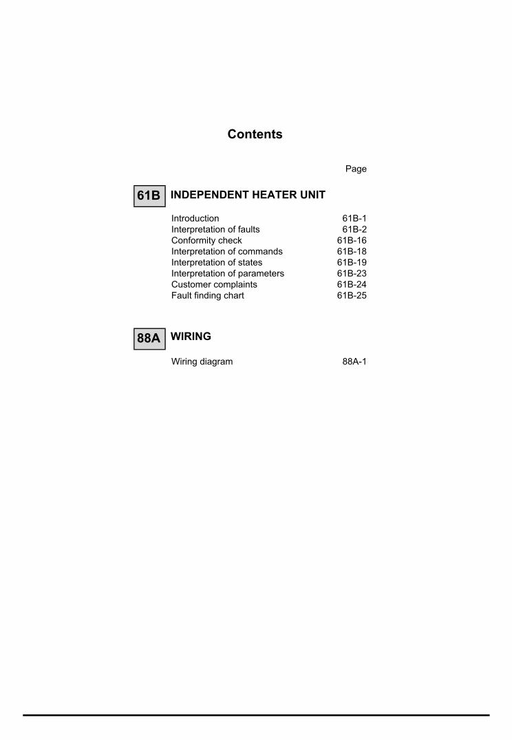
Introduction 61B-1Interpretation of faults 61B-2Conformity check 61B-16Interpretation of commands 61B-18Interpretation of states 61B-19Interpretation of parameters 61B-23Customer complaints 61B-24Fault finding chart 61B-25
WIRING
Wiring diagram 88A-1

INDEPENDENT HEATER UNITFault finding - Introduction 61BProgram No.: 0001
Vdiag No.: 04
161BINDEPENDENT HEATER UNITFault finding - Introduction
GENERAL APPROACH TO FAULT FINDING:
– Use one of the diagnostic tools to identify the system fitted to the vehicle (to read the computer group, the program number, the Vdiag, etc.).
– Locate the Fault finding documents corresponding to the system identified.
– Include information contained in the Introduction sections.
– Read the faults stored in the computer memory and use the Fault interpretation section of the documents.Reminder: each fault is interpreted for a particular type of storage (fault present, fault stored in memory, fault present or stored). The specified checks for dealing with each fault are therefore only to be performed if the fault declared by the diagnostic tool can be identified in the document by its type. The way in which the fault is stored should be considered when using the diagnostic tool after switching the ignition off and on again. If a fault is interpreted when it is declared as stored, the conditions for applying fault finding appear in the NOTES box. When these conditions are not satisfied, use the fault finding procedure to check the circuit of the faulty part, since the fault is no longer present on the vehicle. Perform the same operation when a fault is declared as stored by the diagnostic tool but is only interpreted in the documentation as a present fault.
– Carry out the conformity check (appearance of possible faults not yet identified by the system's self-diagnosis procedure) and apply the relevant fault finding strategies according to the results.
– Confirm the repair (customer complaint disappears).
– Use the fault finding procedure for each Customer complaint if the fault persists.
This document presents the general fault finding procedure applicable to the additional heating function on Espace and Avantime vehicles with a G9T diesel engine.A Fault finding Special notes Technical Note is available for each vehicle fitted with this computer and this function. It covers all the fault finding special notes in this document for the vehicle concerned. This Special notes Note complements or replaces the information provided in the Generic fault finding document.
The following are required for carrying out fault finding on this system:
– the Workshop Repair Manual for the vehicle concerned,– the wiring diagram of the function for the vehicle concerned,– the tools listed in Special tooling required.
61B-1
INDEPENDENT HEATER UNITFault finding - Fault Interpretation 61B
61B-2
Program No.: 0001Vdiag No.: 04 Fault finding - Fault Interpretation
DF001PRESENT
ORSTORED
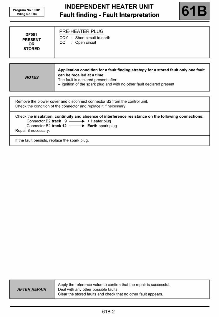
PRE-HEATER PLUGCC.0 : Short circuit to earthCO : Open circuit
NOTES
Application condition for a fault finding strategy for a stored fault only one fault can be recalled at a time:The fault is declared present after:– ignition of the spark plug and with no other fault declared present
Remove the blower cover and disconnect connector B2 from the control unit.Check the condition of the connector and replace it if necessary.
Check the insulation, continuity and absence of interference resistance on the following connections:Connector B2 track 9 + Heater plugConnector B2 track 12 Earth spark plug
Repair if necessary.
If the fault persists, replace the spark plug.
AFTER REPAIRApply the reference value to confirm that the repair is successful.Deal with any other possible faults.Clear the stored faults and check that no other fault appears.
INDEPENDENT HEATER UNITFault finding - Fault Interpretation 61B
61B-3
Program No.: 0001Vdiag No.: 04
DF002PRESENT
ORSTORED
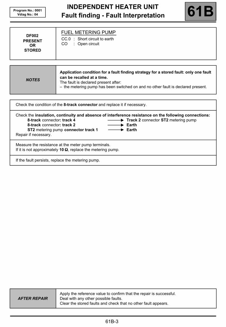
FUEL METERING PUMPCC.0 : Short circuit to earthCO : Open circuit
NOTES
Application condition for a fault finding strategy for a stored fault: only one fault can be recalled at a time.The fault is declared present after:– the metering pump has been switched on and no other fault is declared present.
Check the condition of the 8-track connector and replace it if necessary.
Check the insulation, continuity and absence of interference resistance on the following connections:8-track connector: track 4 Track 2 connector ST2 metering pump8-track connector: track 2 EarthST2 metering pump connector track 1 Earth
Repair if necessary.
Measure the resistance at the meter pump terminals. If it is not approximately 10 ΩΩΩΩ, replace the metering pump.
If the fault persists, replace the metering pump.
AFTER REPAIRApply the reference value to confirm that the repair is successful.Deal with any other possible faults.Clear the stored faults and check that no other fault appears.

INDEPENDENT HEATER UNITFault finding - Fault Interpretation 61B
61B-4
Program No.: 0001Vdiag No.: 04
DF003PRESENT
ORSTORED
COOLANT TEMPERATURE SENSOR CIRCUITCC.0 : Short circuit to earthCO : Open circuit
NOTES
Application condition for a fault finding strategy for a stored fault: only one fault can be recalled at a time.The fault is declared present after:– the boiler has been ignited and with no other fault declared present.
Remove the blower cover and disconnect connector B2 from the control unit.Check the condition of the connector and replace it if necessary.
Check the insulation, continuity and absence of interference resistance on the following connections:Connector B2 track 3 Temperature sensorConnector B2 track 4 Temperature sensor
Repair if necessary.
Measure the resistance at the sensor terminals. If it is not 12 kΩΩΩΩ ±±±± 600 ΩΩΩΩ at 20 °°°°C, replace the heater internal wiring.
If the fault persists, replace the heater.
AFTER REPAIRApply the reference value to confirm that the repair is successful.Deal with any other possible faults.Clear the stored faults and check that no other fault appears.

INDEPENDENT HEATER UNITFault finding - Fault Interpretation 61B
61B-5
Program No.: 0001Vdiag No.: 04
DF004PRESENT
ORSTORED
COMBUSTION AIR FANCC.0 : Short circuit to earthCO : Open circuitDEF : Blocked
NOTES
Application condition for a fault finding strategy for a stored fault: only one fault can be recalled at a timeThe fault is declared present after:– the heater has been ignited and with no other fault declared present.
Remove the blower cover and disconnect connector B2 from the control unit.Check the condition of the connector and replace it if necessary.
Check the insulation, continuity and absence of interference resistance on the following connections:Connector B2 track 14 Earth combustion air fanConnector B2 track 13 + Combustion air ventilation fan
Repair if necessary.
Using a multimeter, check that the winding of the ventilation fan is not cut.Replace the fan if necessary.
AFTER REPAIRApply the reference value to confirm that the repair is successful.Deal with any other possible faults.Clear the stored faults and check that no other fault appears.
INDEPENDENT HEATER UNITFault finding - Fault Interpretation 61B
61B-6
Program No.: 0001Vdiag No.: 04
DF005PRESENT
ORSTORED
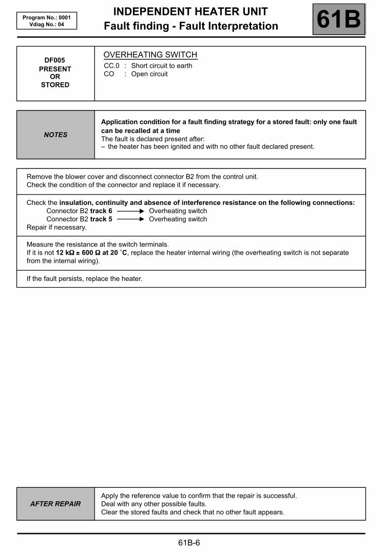
OVERHEATING SWITCHCC.0 : Short circuit to earthCO : Open circuit
NOTES
Application condition for a fault finding strategy for a stored fault: only one fault can be recalled at a timeThe fault is declared present after:– the heater has been ignited and with no other fault declared present.
Remove the blower cover and disconnect connector B2 from the control unit.Check the condition of the connector and replace it if necessary.
Check the insulation, continuity and absence of interference resistance on the following connections:Connector B2 track 6 Overheating switchConnector B2 track 5 Overheating switch
Repair if necessary.
Measure the resistance at the switch terminals. If it is not 12 kΩΩΩΩ ±±±± 600 ΩΩΩΩ at 20 ˚C, replace the heater internal wiring (the overheating switch is not separate from the internal wiring).
If the fault persists, replace the heater.
AFTER REPAIRApply the reference value to confirm that the repair is successful.Deal with any other possible faults.Clear the stored faults and check that no other fault appears.

INDEPENDENT HEATER UNITFault finding - Fault Interpretation 61B
61B-7
Program No.: 0001Vdiag No.: 04
DF006PRESENT
ORSTORED
FLAME DETECTORCC.0 : Short circuit to earthCO : Open circuit
NOTES
Application condition for a fault finding strategy for a stored fault: only one fault can be recalled at a timeThe fault is declared present after:– the heater has been ignited and with no other fault declared present.
Remove the blower cover and disconnect connector B2 from the control unit.Check the condition of the connector and replace it if necessary.
Check the insulation, continuity and absence of interference resistance on the following connections:Connector B2 track 1 Flame detectorConnector B2 track 2 Flame detector
Repair if necessary.
Measure the resistance at the flame detector terminals. If it is not 1200 ΩΩΩΩ ±±±± 60 ΩΩΩΩ at 50 °°°°C, replace the internal wiring (the flame detector is connected to the internal wiring).
Replace the heater if the fault persists.
AFTER REPAIRApply the reference value to confirm that the repair is successful.Deal with any other possible faults.Clear the stored faults and check that no other fault appears.

INDEPENDENT HEATER UNITFault finding - Fault Interpretation 61B
61B-8
Program No.: 0001Vdiag No.: 04
DF008PRESENT
ORSTORED
HEATER MALFUNCTION1.DEF : Overvoltage2.DEF : Undervoltage
NOTES
Application condition for a fault finding strategy for a stored fault: only one fault can be recalled at a timeThe fault is declared present after:– the heater has been ignited and with no other fault declared present.
Check the voltage between tracks 1 and 2 of the 8-track connector. This should be between: 10.2 V < X < 16 V.
Check the insulation, continuity and absence of interference resistance on the following connections:8-track connector: track 1 + Battery8-track connector: track 2 Battery earth
Repair if necessary.
Check the battery and charge circuit if the fault persists.
AFTER REPAIRApply the reference value to confirm that the repair is successful.Deal with any other possible faults.Clear the stored faults and check that no other fault appears.
INDEPENDENT HEATER UNITFault finding - Fault Interpretation 61B
61B-9
Program No.: 0001Vdiag No.: 04
DF010PRESENT
ORSTORED
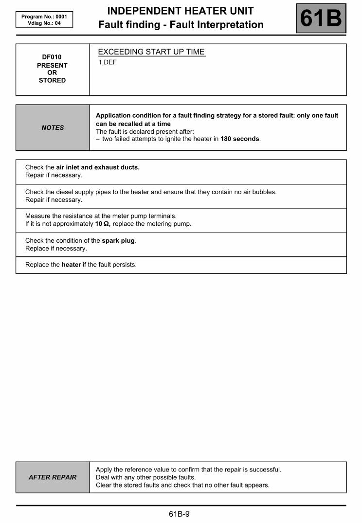
EXCEEDING START UP TIME1.DEF
NOTES
Application condition for a fault finding strategy for a stored fault: only one fault can be recalled at a timeThe fault is declared present after:– two failed attempts to ignite the heater in 180 seconds.
Check the air inlet and exhaust ducts.Repair if necessary.
Check the diesel supply pipes to the heater and ensure that they contain no air bubbles.Repair if necessary.
Measure the resistance at the meter pump terminals. If it is not approximately 10 ΩΩΩΩ, replace the metering pump.
Check the condition of the spark plug.Replace if necessary.
Replace the heater if the fault persists.
AFTER REPAIRApply the reference value to confirm that the repair is successful.Deal with any other possible faults.Clear the stored faults and check that no other fault appears.
INDEPENDENT HEATER UNITFault finding - Fault Interpretation 61B
61B-10
Program No.: 0001Vdiag No.: 04
DF011PRESENT
ORSTORED
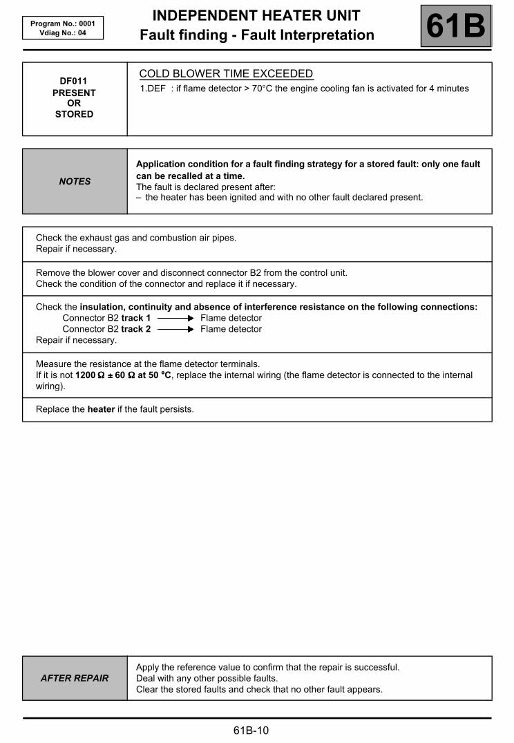
COLD BLOWER TIME EXCEEDED1.DEF : if flame detector > 70°C the engine cooling fan is activated for 4 minutes
NOTES
Application condition for a fault finding strategy for a stored fault: only one fault can be recalled at a time.The fault is declared present after:– the heater has been ignited and with no other fault declared present.
Check the exhaust gas and combustion air pipes.Repair if necessary.
Remove the blower cover and disconnect connector B2 from the control unit.Check the condition of the connector and replace it if necessary.
Check the insulation, continuity and absence of interference resistance on the following connections:Connector B2 track 1 Flame detectorConnector B2 track 2 Flame detector
Repair if necessary.
Measure the resistance at the flame detector terminals.If it is not 1200 ΩΩΩΩ ±±±± 60 ΩΩΩΩ at 50 °°°°C, replace the internal wiring (the flame detector is connected to the internal wiring).
Replace the heater if the fault persists.
AFTER REPAIRApply the reference value to confirm that the repair is successful.Deal with any other possible faults.Clear the stored faults and check that no other fault appears.
INDEPENDENT HEATER UNITFault finding - Fault Interpretation 61B
61B-11
Program No.: 0001Vdiag No.: 04
DF012PRESENT
ORSTORED
CONTROL UNIT1.DEF : Unidentified electrical fault
NOTES
Application condition for a fault finding strategy for a stored fault: only one fault can be recalled at a time.The fault is declared present after:– the heater has been ignited and with no other fault declared present.
Replace the control unit.
AFTER REPAIRApply the reference value to confirm that the repair is successful.Deal with any other possible faults.Clear the stored faults and check that no other fault appears.
INDEPENDENT HEATER UNITFault finding - Fault Interpretation 61B
61B-12
Program No.: 0001Vdiag No.: 04
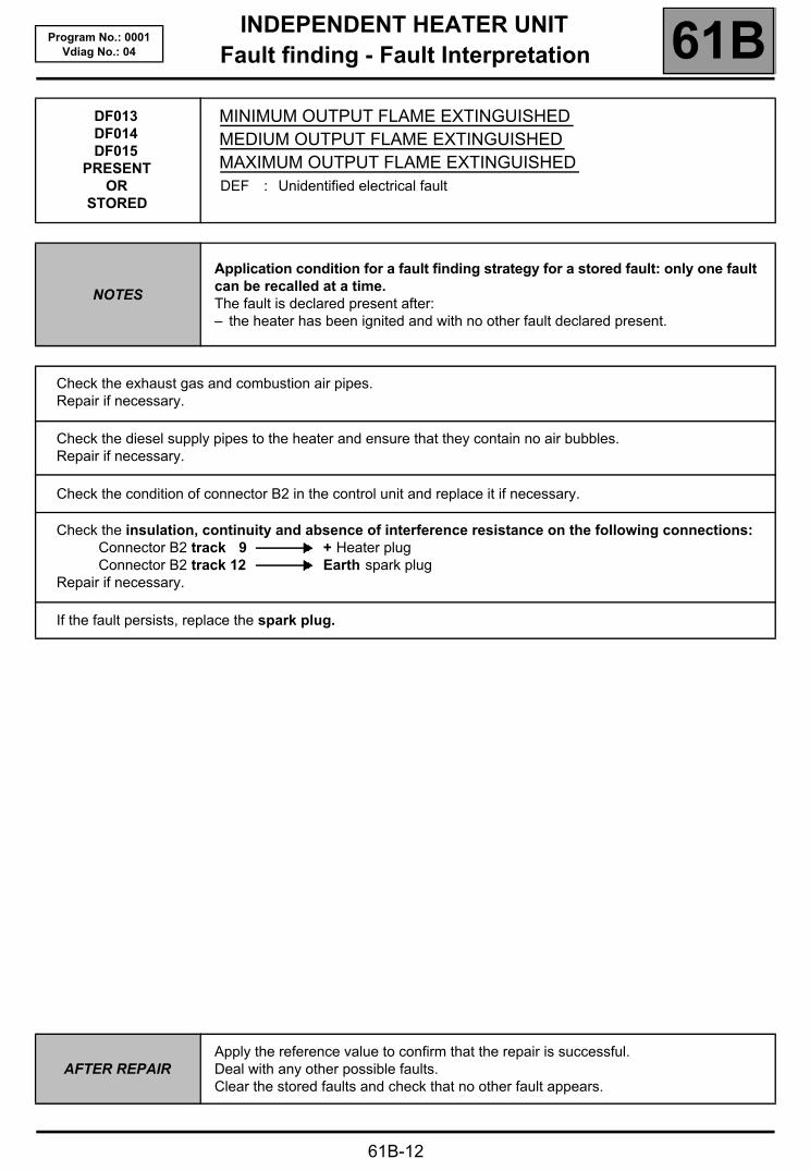
DF013DF014DF015
PRESENTOR
STORED
MINIMUM OUTPUT FLAME EXTINGUISHEDMEDIUM OUTPUT FLAME EXTINGUISHEDMAXIMUM OUTPUT FLAME EXTINGUISHEDDEF : Unidentified electrical fault
NOTES
Application condition for a fault finding strategy for a stored fault: only one fault can be recalled at a time.The fault is declared present after:– the heater has been ignited and with no other fault declared present.
Check the exhaust gas and combustion air pipes.Repair if necessary.
Check the diesel supply pipes to the heater and ensure that they contain no air bubbles.Repair if necessary.
Check the condition of connector B2 in the control unit and replace it if necessary.
Check the insulation, continuity and absence of interference resistance on the following connections:Connector B2 track 9 + Heater plugConnector B2 track 12 Earth spark plug
Repair if necessary.
If the fault persists, replace the spark plug.
AFTER REPAIRApply the reference value to confirm that the repair is successful.Deal with any other possible faults.Clear the stored faults and check that no other fault appears.

INDEPENDENT HEATER UNITFault finding - Fault Interpretation 61B
61B-13
Program No.: 0001Vdiag No.: 04
DF016DF017DF018
PRESENTOR
STORED
DETECTION OF OVERHEATING: LOW PROBABILITYDETECTION OF OVERHEATING: PROBABLEDETECTION OF OVERHEATING: CONFIRMEDDEF: Unidentified electrical fault
NOTES
Application condition for a fault finding strategy for a stored fault: only one fault can be recalled at a time.The fault is declared present after:– the heater has been ignited and with no other fault declared present.
Special notes:Probable: temperature difference of 15 °°°°C between the sensor and the overheating switch.Confirmed: temperature at the sensor or switch > 125 °°°°CLow probability: temperature threshold exceeded, sensor or switch > 130 °°°°C.
Check the circulation of water through the system.Ensure that it is thoroughly degassed.
Remove the blower cover and disconnect connector B2 from the control unit.Check the condition of the connector and replace it if necessary.
Check the insulation, continuity and absence of interference resistance on the following connections:Connector B2 track 3 Temperature sensorConnector B2 track 4 Temperature sensorConnector B2 track 5 Overheating switchConnector B2 track 6 Overheating switch
Repair if necessary.
Measure the resistance at the sensor terminals. If it is not 12 kΩΩΩΩ ±±±± 600 ΩΩΩΩ at 20 °°°°C, replace the heater internal wiring.Measure the resistance at the switch terminals. If it is not 12 kΩΩΩΩ ±±±± 600 ΩΩΩΩ at 20 °°°°C, replace the heater internal wiring.
If the fault persists, replace the heater.
AFTER REPAIRApply the reference value to confirm that the repair is successful.Deal with any other possible faults.Clear the stored faults and check that no other fault appears.

INDEPENDENT HEATER UNITFault finding - Fault Interpretation 61B
61B-14
Program No.: 0001Vdiag No.: 04
DF019PRESENT
ORSTORED
BLOCK: TOO MANY SUCCESSIVE START UPSDEF: Unidentified electrical fault
NOTES
Priority when dealing with a number of faults:If more than one of the faults DF019 and DF001, DF002 are stored, treat as a priority faults DF001 Pre-heater plug and DF002 Metering pump.
Application condition for a fault finding strategy for a stored fault: only one fault can be recalled at a time.The fault is declared present after:– 10 failed attempts to ignite the heater and with no other faults declared present.
Clear incorrect start up counter using the delete command RZ002.
AFTER REPAIRApply the reference value to confirm that the repair is successful.Deal with any other possible faults.Clear the stored faults and check that no other fault appears.

INDEPENDENT HEATER UNITFault finding - Fault Interpretation 61B
61B-15
Program No.: 0001Vdiag No.: 04
DF020 PRESENT
OR STORED
BLOCK: TOO MUCH SUCCESSIVE OVERHEATINGDEF: Unidentified electrical fault
NOTES
Application condition for a fault finding strategy for a stored fault: only one fault can be recalled at a time.The fault is declared present after:– 10 failed attempts to ignite the heater and with no other faults declared present.
Delete overheating meter using the clear control RZ001.
AFTER REPAIRApply the reference value to confirm that the repair is successful.Deal with any other possible faults.Clear the stored faults and check that no other fault appears.
INDEPENDENT HEATER UNITFault finding - Conformity check 61B
61B-16
Program No.: 0001Vdiag No.: 04 Fault finding - Conformity check
NOTES
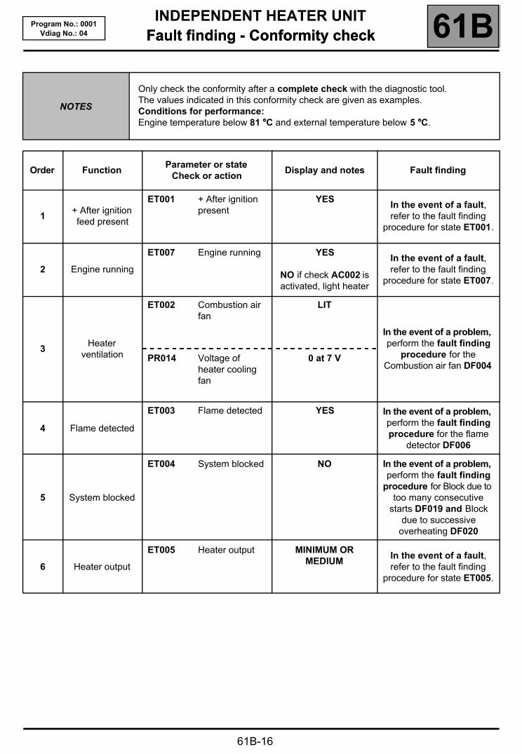
Only check the conformity after a complete check with the diagnostic tool.The values indicated in this conformity check are given as examples.Conditions for performance:Engine temperature below 81 °°°°C and external temperature below 5 °°°°C.
Order FunctionParameter or state
Check or action Display and notes Fault finding
1+ After ignition feed present
ET001 + After ignition present
YESIn the event of a fault, refer to the fault finding
procedure for state ET001.
2 Engine running
ET007 Engine running YES
NO if check AC002 is activated, light heater
In the event of a fault, refer to the fault finding
procedure for state ET007.
3Heater
ventilation
ET002 Combustion air fan
LIT
In the event of a problem, perform the fault finding
procedure for the Combustion air fan DF004
PR014 Voltage of heater cooling fan
0 at 7 V
4 Flame detected
ET003 Flame detected YES In the event of a problem, perform the fault finding procedure for the flame
detector DF006
5 System blocked
ET004 System blocked NO In the event of a problem, perform the fault finding
procedure for Block due to too many consecutive
starts DF019 and Block due to successive
overheating DF020
6 Heater output
ET005 Heater output MINIMUM OR MEDIUM
In the event of a fault, refer to the fault finding
procedure for state ET005.

INDEPENDENT HEATER UNITFault finding - Conformity check 61B
61B-17
Program No.: 0001Vdiag No.: 04
NOTES
Only check the conformity after a complete check with the diagnostic tool.The values indicated in this conformity check are given as examples.Conditions for performance:Engine temperature below 81 °°°°C and external temperature below 5 °°°°C.
Order FunctionParameter or state
Check or action Display and notes Fault finding
9Overheating
switch
PR008 Overheating switch value measured
Overheats if the temperature is above
125 °°°°C
If there is a problem, perform the fault finding
procedure on the Overheating switch
DF005.
10Coolant
temperature sensor
PR010 Coolant temperature sensor value measured
X = Engine temperature ±±±± 5 °°°°C
If there is a problem, perform the fault finding
procedure on the Coolant temperature sensor circuit.
DF003.
11 Flame detector
PR013 Flame detector value measured
X = Heater temperature ±±±± 20 °°°°C
In the event of a problem, perform the fault finding procedure for the Flame
detector DF006.
12Computer
supply voltage
PR108 Computer supply voltage
10.2 V < X < 16 V In the event of a problem, refer to the fault finding procedure for parameter
PR108.
13Spark plug feed
instruction
PR016 Spark plug feed instruction
None If there is a problem, perform the fault finding procedure DF001 on the
Faulty pre-heater plug.
14Fuel pump command frequency
PR017 Fuel pump command frequency
X = frequency in Hz ±±±± 5%
If there is a problem, perform the fault finding procedure on the Fuel metering pump DF002.

INDEPENDENT HEATER UNITFault finding - Command interpretation 61B
61B-18
Program No.: 0001Vdiag No.: 04 Fault finding - Command interpretation
AC002
AC003
HEATER CONTROLAC002 : Ignite the heaterAC003 : Extinguish the heater
NOTESIMPORTANT: during heater control, it is essential that the engine is running to avoid any overheating due to non-circulation of water.
The heater may be started or stopped using the command menu on the diagnostic tool.If it fails to start, check:
– there is fuel in the tank,– that the fuses are intact– that the combustion air and exhaust pipes are not plugged.
Repair if necessary.
Check the connection and the condition of the intermediary 5-track connector between the vehicle wiring and the heater and replace if necessary.
Check the insulation, continuity and absence of interference resistance on the connections between:+ Battery Track A 5-track connectorEarth Track D 5-track connector+ 12 V after ignition Track E 5-track connectorDiagnostic socket Track B 5-track connector
Repair if necessary.
If the fault persists, replace the heater.

INDEPENDENT HEATER UNITFault finding - Interpretation of states 61B
61B-19
Program No.: 0001Vdiag No.: 04 Fault finding - Interpretation of states
ET001
+ AFTER IGNITION PRESENT
NOTES None.
If the state is INACTIVE, check that the battery charge is above 10.2 V.Otherwise repair the vehicle's charge circuit.
Check the connection and the condition of the intermediate 5-track connector between the vehicle wiring and the heater and replace if necessary.Check the connection and condition of the intermediate 8-track connector located on the heater mounting.
Check the insulation, continuity and absence of interference resistance on the connections between:+ Battery Track 1 8-track connectorEarth Track 2 8-track connector+ 12 V after ignition Track 7 8-track connector
Repair if necessary.
Replace the heater control unit if the fault persists.
INDEPENDENT HEATER UNITFault finding - Interpretation of states 61B
61B-20
Program No.: 0001Vdiag No.: 04
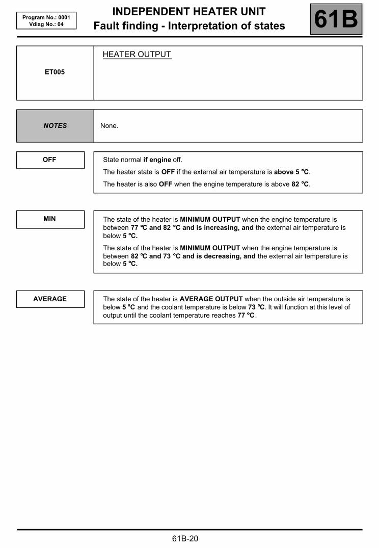
ET005
HEATER OUTPUT
NOTES None.
OFF
MIN
AVERAGE
State normal if engine off.
The heater state is OFF if the external air temperature is above 5 °°°°C.
The heater is also OFF when the engine temperature is above 82 °°°°C.
The state of the heater is MINIMUM OUTPUT when the engine temperature is between 77 °°°°C and 82 °°°°C and is increasing, and the external air temperature is below 5 °°°°C.
The state of the heater is MINIMUM OUTPUT when the engine temperature is between 82 °°°°C and 73 °°°°C and is decreasing, and the external air temperature is below 5 °°°°C.
The state of the heater is AVERAGE OUTPUT when the outside air temperature is below 5 °°°°C and the coolant temperature is below 73 °°°°C. It will function at this level of output until the coolant temperature reaches 77 °°°°C.
INDEPENDENT HEATER UNITFault finding - Interpretation of states 61B
61B-21
Program No.: 0001Vdiag No.: 04
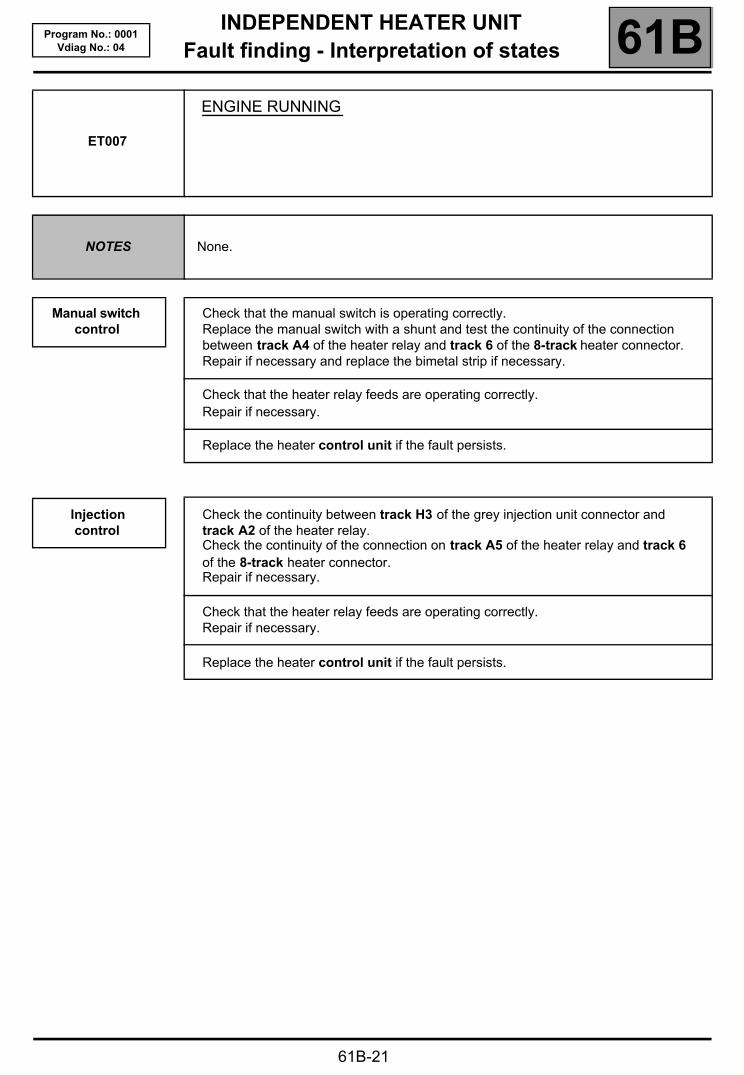
ET007
ENGINE RUNNING
NOTES None.
Manual switch control
Injection control
Check that the manual switch is operating correctly.Replace the manual switch with a shunt and test the continuity of the connection between track A4 of the heater relay and track 6 of the 8-track heater connector.Repair if necessary and replace the bimetal strip if necessary.
Check that the heater relay feeds are operating correctly.Repair if necessary.
Replace the heater control unit if the fault persists.
Check the continuity between track H3 of the grey injection unit connector and track A2 of the heater relay.Check the continuity of the connection on track A5 of the heater relay and track 6 of the 8-track heater connector.Repair if necessary.
Check that the heater relay feeds are operating correctly.Repair if necessary.
Replace the heater control unit if the fault persists.

INDEPENDENT HEATER UNITFault finding - Parameter interpretation 61B
61B-22
Program No.: 0001Vdiag No.: 04 Fault finding - Parameter interpretation
PR108
COMPUTER SUPPLY VOLTAGE
NOTES None.
Check the connection and the condition of the intermediate 5-track connector between the vehicle wiring and the heater and replace if necessary.
Check the insulation, continuity and absence of interference resistance on the connections between:+ Battery Track A 5-track connectorEarth Track D 5-track connector+ 12 V after ignition Track E 5-track connector
Repair if necessary.
Check the insulation, continuity and absence of interference resistance on the connections between:Track A 5-track connector Track 1 8-track connectorTrack D 5-track connector Track 2 8-track connectorTrack E 5-track connector Track 7 8-track connector
Repair if necessary.Replace the heater control unit if the fault persists.
INDEPENDENT HEATER UNITFault finding - Customer complaints 61B
61B-23
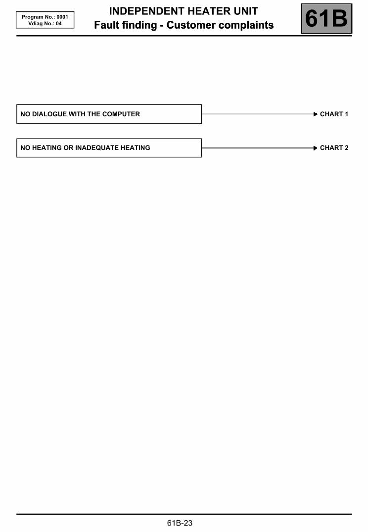
Program No.: 0001Vdiag No.: 04 Fault finding - Customer complaints
NO DIALOGUE WITH THE COMPUTER CHART 1
NO HEATING OR INADEQUATE HEATING CHART 2

INDEPENDENT HEATER UNITFault finding - Fault finding chart 61B
61B-24
Program No.: 0001Vdiag No.: 04 Fault finding - Fault finding chart
CHART 1 No dialogue with the computer
NOTES Only consult this customer complaint after a complete check using the diagnostic tool.
Try the diagnostic tool on another vehicle.
Check:– the connection between the diagnostic tool and the diagnostic socket (wiring in good condition),– the engine fuses.
Check for the presence of + 12 volts before ignition on track 16, for + 12 volts after ignition on track 1 and for an earth on tracks 4 and 5 of the diagnostic socket.Repair if necessary.
Check the insulation, continuity and absence of interference resistance on the connections between:Connector ST1 track A V Battery (fuse box)Connector ST1 track E + After ignition feed (fuse box)Connector ST1 track D EarthConnector ST1 track B Track 7 of the diagnostic socket (line K)
Repair if necessary.
AFTER REPAIR Check that the system is operating correctly.
INDEPENDENT HEATER UNITFault finding - Fault finding chart 61B
61B-25
Program No.: 0001Vdiag No.: 04
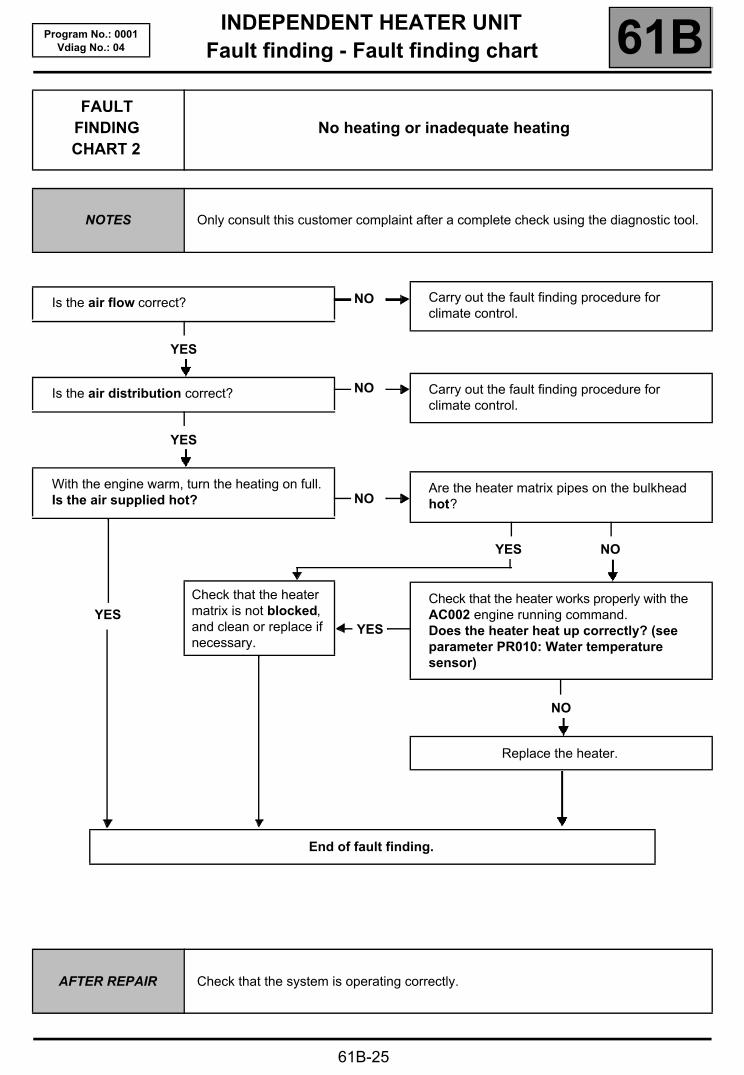
FAULT FINDING CHART 2
No heating or inadequate heating
NOTES Only consult this customer complaint after a complete check using the diagnostic tool.
Is the air flow correct?
YES
Is the air distribution correct?
YES
With the engine warm, turn the heating on full.Is the air supplied hot?
YES
NO
NO
NO
YES
Check that the heater matrix is not blocked, and clean or replace if necessary.
Carry out the fault finding procedure for climate control.
Carry out the fault finding procedure for climate control.
Are the heater matrix pipes on the bulkhead hot?
YES NO
Check that the heater works properly with the AC002 engine running command.Does the heater heat up correctly? (see parameter PR010: Water temperature sensor)
NO
Replace the heater.
End of fault finding.
AFTER REPAIR Check that the system is operating correctly.
WIRINGHeater wiring diagram 88A
88A-1
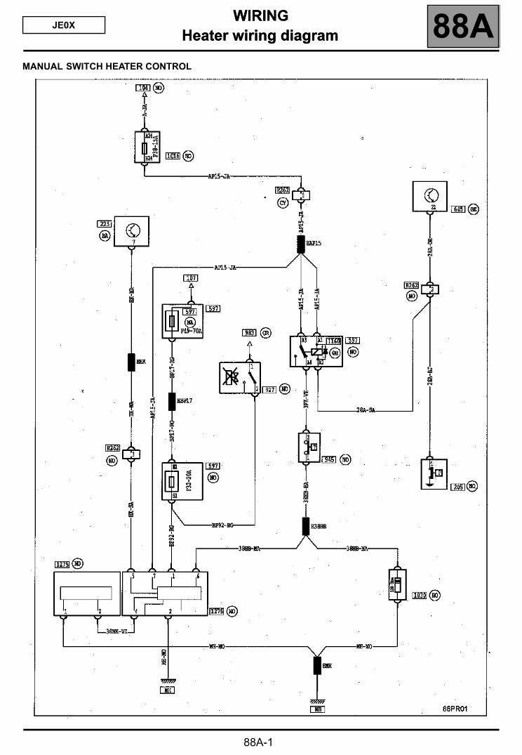
JE0X288AWIRING
Heater wiring diagram
MANUAL SWITCH HEATER CONTROL
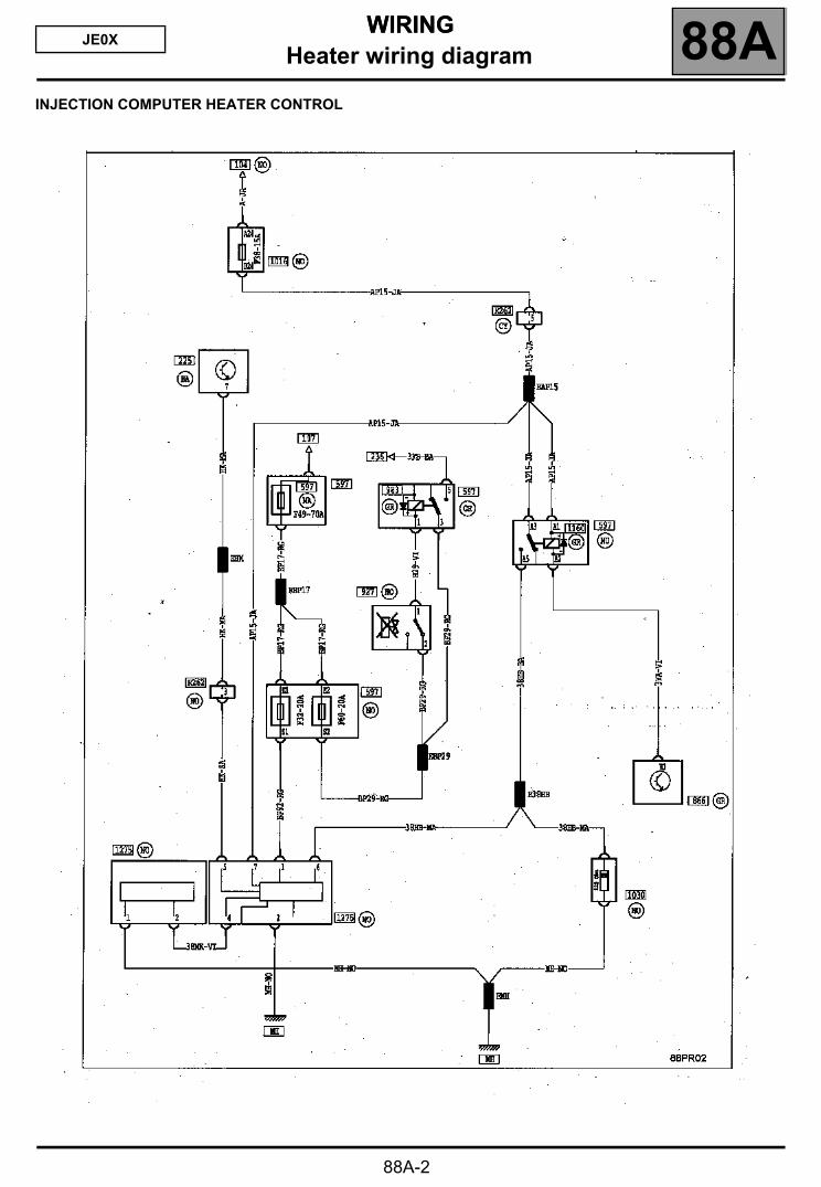
WIRINGHeater wiring diagram 88AJE0X
WIRING
INJECTION COMPUTER HEATER CONTROL
88A-2


