
MVIP™ Product Catalog www.MVIPpro.com
Modular Vacuum Insulated PipeSystem Solutions for Cryogenic Liquid Service
MODULAR SYSTEMS | ACCESSORIES | SYSTEM DESIGN | MANUFACTURING | INSTALLATION | SERVICE

On the cover: Chart offers a wide range of modular vacuum insulated pipe solutions.
Here: Chart offers a wide range of end-user equipment for LN
2 service including
Cryopreservation freezers and dosers.

An efficient supply of high-quality liquid nitrogen is needed to keep valuable biological samples stored indefinitely. Today’s top medical research facilities depend on a reliable liquid nitrogen supply to find cures for tomorrow’s diseases. Any interruption in supply can result in the loss of many years of research. Chart’s experience in the biological container market makes us the first choice in vacuum insulated pipe systems for these applications.
BIOLOGICAL STORAGE AND RESEARCH
Using nitrogen to create positive pressure for a rigid container and displace oxygen for a longer shelf-life requires a consistent flow of quality liquid nitrogen to the doser. With Chart’s engineered system solutions from the bulk tank to the doser, you get a reliable supply of liquid nitrogen that keeps your equipment operating at peak efficiency for maximum productivity.
FOOD AND BEVERAGE PACKAGING
Chart’s vacuum insulated pipe is used on launch pads, delivering extremely high flow rates of liquid hydrogen and oxygen to fuel today’s demanding space programs. Aerospace applications are extremely precise, requiring larger diameters, higher pressures and intense analysis of engineering stress and heat leak. Additionally, Chart is able to meet the precision cleaning requirements common to these applications.
AEROSPACE
VACUUM INSULATED PIPE

Total system cost and efficiency is crucial in food freezing applications. Chart’s superior insulation technology delivers liquid nitrogen with more cooling capacity, using less nitrogen per pound of frozen product. With our experience and capabilities in providing complete pipe system solutions, we help maintain the lowest total cost of ownership with the most efficient system.
FOOD FREEZING
Silicone wafer manufacturing and cleaning applications require extremely tight tolerances on the control of liquid nitrogen flow. It is critical that the vacuum insulated pipe system delivers the proper amount of liquid at the proper temperature to maximize wafer yield. For electronic component testing, Chart works with today’s leading equipment manufacturers to design and manufacture pipe systems that supply the flows demanded by today’s thermal stress and environmental test chambers.
ELECTRONIC MANUFACTURING AND TESTING
MBE is a method of laying down layers of materials with atomic thicknesses on a substrate (epitaxial growth). This is done by creating a “molecular beam” of a material which impinges on the substrate in a high-quality vacuum. A cryogenic screening around the substrate minimizes fluxes of atoms from the walls of the chamber. During this process, it is imperative that the supply of liquid nitrogen be uninterrupted and of good quality (the right pressure and temperature) to prevent contamination of the substrate or interruption of the process.
MOLECULAR BEAM EPITAXY
Flexible, efficient piping delivery systems for all your cryogenic liquid needs.

www.mvippro.com 1
Modular Vacuum Insulated Pipe MVIP™ − Superiority Through ExperienceChart is the world’s leading designer, manufacturer and installer of standard and custom vacuum insulated pipe (VIP) systems. Our industry-leading 40 years of experience covers the spectrum of traditional industry applications, from heat-leak sensitive helium lines to highly engineered aerospace applications. Our vacuum insulated pipe systems are built in an ISO 9001:2008 and ISO 14001:2004 approved manufacturing facility. This sophisticated facility shares manufacturing with our tank product lines, giving us the resources and flexibility to adjust our pipe manufacturing capacity to market demands. This enables us to keep our lead times and costs down while maintaining superior product quality. Our wide product offering of pipe and accessories allows us to engineer the optimum system solutions for any liquid application.
COMPLETE INTEGRATED SYSTEMS: From vacuum insulated tank and piping components to controls to application equipment, Chart has the experience and expertise to deliver a complete, turnkey cryogenic delivery system.
QUALITY MANUFACTURING: Our equipment is built for efficiency and built to last. Our experience and ISO 9001 certification ensures that your job is completed to the highest quality standards and on schedule.
FLEXIBLE MODULAR SOLUTIONS: Chart delivers the quality and flexibility you need, with pre-engineered MVIP Pro® and MVIP Python® Vacuum Insulated Pipe standard modules from which you can design your VIP system with the guidance of the Chart Modulator™ MVIP Ordering Software or knowledgeable Chart sales staff.
CUSTOM-ENGINEERED SOLUTIONS: If you need a robust, custom-engineered VIP system, our planning team will document your system specifications and our engineering team will propose the most efficient and economical MVIP Select® solution to meet your system’s performance requirements.
INSTALLATION AND STARTUP: Certified technicians provide installation and
CONTENTSMVIP™ Overview 2–7
Ì Total System Solution 2-3
Ì MVIP Modulator™ 4-5
Ì Product Guide 6
Ì Smart Numbering System 7
Normal Pressure – MVIP Pro® 9–15
Ì Overview & Liquid Applications 9
Ì Modules 10–14
Ì Technical Information 15
High Pressure – MVIP Python® 17–21
Ì Overview & Liquid Applications 17
Ì Modules 18–21
Custom Engineered – MVIP Select® 23–25
Ì Overview 23
Ì Comparison 24-25
Accessories 26–28
Ì Options 26-27
Ì C-Flex 28
Service & Support / Contact Us 29

2 Ì Chart Inc.
M V I P ™ O ve r v i e w
Gas A
pplication
Vaporizer
Vaporizer
VaporizerSwitch
VJ Outlet
House Line Gas
Final LineRegulator
Bulk Tank120 PSI
APPS 16030 PSI
Liquid Application
Cryovent
O2 Monitor Emergency Stop Button
E-Stop System
Flex Hose
BiologicalFreezer
Cryo-Tempering Processor
Test Chamber
E
VJ Valve
LN2 Doser Food Freezer
End-Use Application

www.mvippro.com 3
M V I P ™ O ve r v i e w
Gas A
pplication
Vaporizer
Vaporizer
VaporizerSwitch
VJ Outlet
House Line Gas
Final LineRegulator
Bulk Tank120 PSI
APPS 16030 PSI
Liquid Application
Cryovent
O2 Monitor Emergency Stop Button
E-Stop System
Flex Hose
BiologicalFreezer
Cryo-Tempering Processor
Test Chamber
E
VJ Valve
LN2 Doser Food Freezer
End-Use Application
Liquefied gases are stored at ultra-cold temperatures in a vacuum insulated tank.
Controls on the tank keep the pressure of the liquid at optimum levels to assure proper liquid delivery to the application.
Vacuum insulated pipe connects the tank’s liquid withdrawal to the application
equipment. The pipe is the foundation for the system’s heat-loss efficiency and long-term integrity. It must be engineered to work with the associated controls and accessories.
Chart manufactures equipment that controls and provides gas to other applications within
the facility. Our engineers can help provide proper sizing for vaporizers, control manifolds, etc. to serve both a liquid and gas application from a single bulk tank liquid source.
The application equipment is designed to utilize liquid at specific properties. The system
design must take careful consideration of the application and equipment requirements and specifications.
TOTAL SYSTEM SOLUTION
Our

4 Ì Chart Inc.
M V I P ™ O ve r v i e w
Design your own VIP system with Chart’s Modulator™ MVIP Ordering Software, using MVIP Pro® & Python® modules:
Easily builds an MVIP Pro & Python system in 3D with standard components
Automatically calculates pressure drop in pipe to optimize pipe size
Full parts list with complete proposal simplifies ordering process
Accurate drawings show layout dimensions that can be used as an installation guide
Fast, accurate and available 24/7 from any computer, anywhere in the world
Online help videos show how to use the Modulator’s many features
Combine MVIP Pro & Python piping with custom engineered solutions: consult Chart Inside Sales.
DESIGN YOUR OWN MVIP™ SYSTEM WITH THE MODULATOR™ MVIP ORDERING SOFTWARE.
Fast. Easy. Accurate.
USE YOUR ChartParts.com username and password to sign onto the Modulator. Both
simple and complex systems can be configured with this tool. A design team will review your specifications, sketch and proposed drawing, so you can be sure your VIP system will be safe, efficient and capable.
THE ISOMETRIC GRID will help you lay out your circuit in three dimensions.
Configuration logic is used to present only valid modules in the pallet.
www.mvippro.com 5
M V I P ™ O ve r v i e w
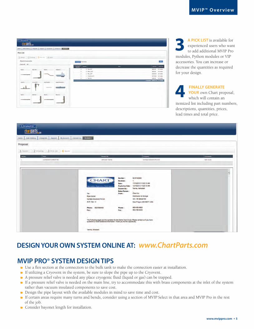
www.ChartParts.comDESIGN YOUR OWN SYSTEM ONLINE AT:
A PICK LIST is available for experienced users who want to add additional MVIP Pro
modules, Python modules or VIP accessories. You can increase or decrease the quantities as required for your design.
FINALLY GENERATE YOUR own Chart proposal, which will contain an
itemized list including part numbers, descriptions, quantities, prices, lead times and total price.
MVIP PRO® SYSTEM DESIGN TIPS Use a flex section at the connection to the bulk tank to make the connection easier at installation. If utilizing a Cryovent in the system, be sure to slope the pipe up to the Cryovent. A pressure relief valve is needed any place cryogenic fluid (liquid or gas) can be trapped. If a pressure relief valve is needed on the main line, try to accommodate this with brass components at the inlet of the system rather than vacuum insulated components to save cost. Design the pipe layout with the available modules in mind to save time and cost. If certain areas require many turns and bends, consider using a section of MVIP Select in that area and MVIP Pro in the rest of the job. Consider bayonet length for installation.
6 Ì Chart Inc.
M V I P ™ O ve r v i e w
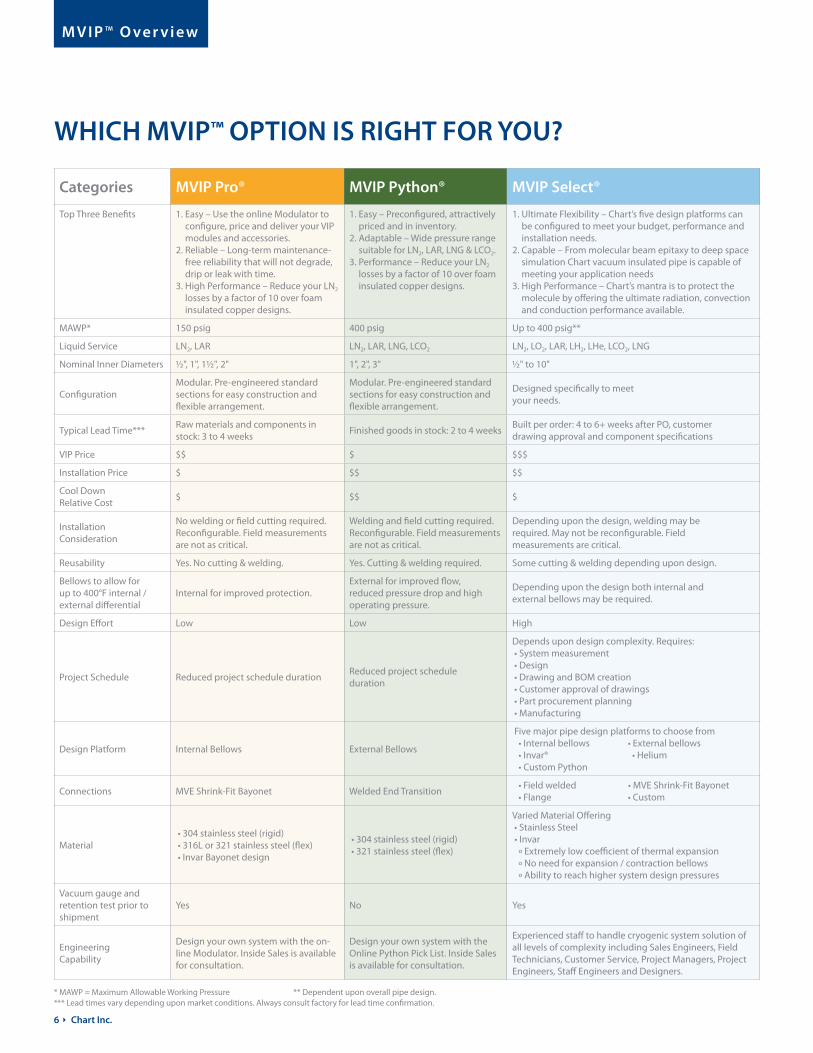
WHICH MVIP™ OPTION IS RIGHT FOR YOU?
Categories MVIP Pro® MVIP Python® MVIP Select®
Top Three Benefits 1. Easy – Use the online Modulator to configure, price and deliver your VIP modules and accessories.
2. Reliable – Long-term maintenance-free reliability that will not degrade, drip or leak with time.
3. High Performance – Reduce your LN2 losses by a factor of 10 over foam insulated copper designs.
1. Easy – Preconfigured, attractively priced and in inventory.
2. Adaptable – Wide pressure range suitable for LN2, LAR, LNG & LCO2.
3. Performance – Reduce your LN2 losses by a factor of 10 over foam insulated copper designs.
1. Ultimate Flexibility – Chart’s five design platforms can be configured to meet your budget, performance and installation needs.
2. Capable – From molecular beam epitaxy to deep space simulation Chart vacuum insulated pipe is capable of meeting your application needs
3. High Performance – Chart’s mantra is to protect the molecule by offering the ultimate radiation, convection and conduction performance available.
MAWP* 150 psig 400 psig Up to 400 psig**
Liquid Service LN2, LAR LN2, LAR, LNG, LCO2 LN2, LO2, LAR, LH2, LHe, LCO2, LNG
Nominal Inner Diameters ½", 1", 1½", 2" 1", 2", 3" ½" to 10"
ConfigurationModular. Pre-engineered standard sections for easy construction and flexible arrangement.
Modular. Pre-engineered standard sections for easy construction and flexible arrangement.
Designed specifically to meet your needs.
Typical Lead Time***Raw materials and components in stock: 3 to 4 weeks
Finished goods in stock: 2 to 4 weeksBuilt per order: 4 to 6+ weeks after PO, customer drawing approval and component specifications
VIP Price $$ $ $$$
Installation Price $ $$ $$
Cool Down Relative Cost
$ $$ $
Installation Consideration
No welding or field cutting required. Reconfigurable. Field measurements are not as critical.
Welding and field cutting required. Reconfigurable. Field measurements are not as critical.
Depending upon the design, welding may be required. May not be reconfigurable. Field measurements are critical.
Reusability Yes. No cutting & welding. Yes. Cutting & welding required. Some cutting & welding depending upon design.
Bellows to allow for up to 400°F internal / external differential
Internal for improved protection.External for improved flow, reduced pressure drop and high operating pressure.
Depending upon the design both internal and external bellows may be required.
Design Effort Low Low High
Project Schedule Reduced project schedule durationReduced project schedule duration
Depends upon design complexity. Requires: • System measurement • Design • Drawing and BOM creation • Customer approval of drawings • Part procurement planning • Manufacturing
Design Platform Internal Bellows External Bellows
Five major pipe design platforms to choose from • Internal bellows • External bellows • Invar® • Helium • Custom Python
Connections MVE Shrink-Fit Bayonet Welded End Transition • Field welded • MVE Shrink-Fit Bayonet • Flange • Custom
Material • 304 stainless steel (rigid) • 316L or 321 stainless steel (flex) • Invar Bayonet design
• 304 stainless steel (rigid) • 321 stainless steel (flex)
Varied Material Offering • Stainless Steel • Invar º Extremely low coefficient of thermal expansion º No need for expansion / contraction bellows º Ability to reach higher system design pressures
Vacuum gauge and retention test prior to shipment
Yes No Yes
Engineering Capability
Design your own system with the on-line Modulator. Inside Sales is available for consultation.
Design your own system with the Online Python Pick List. Inside Sales is available for consultation.
Experienced staff to handle cryogenic system solution of all levels of complexity including Sales Engineers, Field Technicians, Customer Service, Project Managers, Project Engineers, Staff Engineers and Designers.
* MAWP = Maximum Allowable Working Pressure ** Dependent upon overall pipe design.*** Lead times vary depending upon market conditions. Always consult factory for lead time confirmation.

www.mvippro.com 7
M V I P ™ O ve r v i e w
SMART NUMBERING SYSTEM For additional information on components, see details on pages 10-24.
Glossary
Ordering Chart MVIP Pro®, MVIP Python® and MVIP Select® Vacuum Insulated Pipe modules is simple with Chart’s smart numbering system. Smart model numbering allows for more integrated options. It also lets you be sure you have selected the options you want.
Each segment of the Smart Model Number refers to one attribute of the module, as shown below, including Pro, Python or Select, the inner pipe size, the type of module, the effective length, the end terminations, the transition location, the outer construction, and the certifications.
The template below shows the option choices within each attribute. Sample Smart Model Numbers are shown by each of the modules in the following pages in the following format.
ProductInner
Pipe Size
TransitionLocation/
End3Outer
ConstructionModule
TypeEnd1
TerminationEnd2
TerminationEffective Length Options
– – – – – – – –
LN2: Liquid Nitrogen
LAR: Liquid Argon
LNG: Liquefied Natural Gas
LO2: Liquid Oxygen
LCO2: Liquid Carbon Dioxide
LH2: Liquid Hydrogen
LHe: Liquid Helium
PRODUCT: Select either PR = Pro, PY = Python or SE = Select to choose the VIP platform
INNER PIPE SIZE: Specifies the nominal inner diameter
MODULE TYPE: Defines the type of module: straight, flex, elbow…
EFFECTIVE LENGTH: Specifies effective pipe length in inches or millimeters
END1 TERMINATION: Type of fitting for one end of the module
END2 TERMINATION: Type of fitting for the second end of the module
TRANSITION LOCATION: Defines if the reduction occurs near End1 or End2
OUTER CONSTRUCTION: External finish of the module
OPTIONS: Defines any additional testing required or other optionsSMA
RT
NU
MB
ERIN
G S
YST
EM
LIQ
UID
SER
VIC
E
MVIP Product (select one) PR = ProPY = Python SE = Select
Module Type
PR = Plain Pipe RigidPF = Plain Pipe FlexFE = Fixed ElbowLE = Long ElbowFT = Female Branch TMT = Male Branch TGT = Gas TrapVY = Valve YVT = Valve TCV = CryoventAD = AdapterTK = Tee KitEK = Elbow KitSK = Straight KitIN = InvarIB = Internal BellowsEB = External BellowsHE = HeliumCP = Custom PythonAC = AccessoryCX = Cross
Inner Pipe Size
08 = ½"10 = 5 8”16 = 1"20 = 1¼”24 = 1½"32 = 2"48 = 3"64 = 4"96 = 6"
Effective Length
XXX.X = in.XXXXX = mmNOTAP = Not
Applicable
(See pages 10 to 18 for stan- dard lengths)
End Terminations &Transition Location / End3 (Tee Modules only)
MBXX = Male BayonetFBXX = Female BayonetPYXX = PythonBWXX = Butt WeldMPXX = Male Pipe ThreadFPXX = Female Pipe ThreadN = None
XX08 = ½"(1)
10 = 5 8"(2)
16 = 1"(1)
20 = 1¼"(2)
24 = 1½"(1)
32 = 2"(1)
48 = 3"(1)
64 = 4"(1)
80 = 5"(1)
96 = 6"(1)
Outer Construction
R = RigidB = BraidedS = Spiral WrapC = Convoluted
Options(add as required)
X = X-RayP = Pressure TestA = ASME InspectionO = O2 CleanN = NoneS = Special, Consult FactoryH = High Shine Outer
End2End1
Effective Length
Overall Length
End2End1
Effective Length
Overall Length
MVIP Pro® Python®
Model 10 20
Inner Diameter (ID) 5 8” (15.875 mm) 1¼" (31.75 mm)
Outer Diameter (OD) 1.8" (45.7 mm) 2.6" (66.04 mm)
Minimum Flexible Bend Radius 18" (457.2 mm) 30" (762 mm)
Hole Required 3" (75 mm) 4" (100 mm)
Maximum Operating Pressure 200 psi (13.8 bar) 125 psi (8.6 bar)
(1) MVE Shrink-Fit Bayonets only
MVIP Select® Flex Technical Information
(2) Close Tolerance Bayonets only
/
/
/

8 Ì Chart Inc.
N o r m a l Pre s s u re – M V I P Pro

www.mvippro.com 9
N o r m a l Pre s s u re – M V I P Pro ®
for Normal Pressure ApplicationsMVIP Pro®
OVERVIEWWherever you are in the world, Chart MVIP Pro® Vacuum Insulated Pipe can be configured, priced, delivered and installed quickly to meet your liquid industrial gas needs.
Easy: Simple installation with standard modules and quick bayonet connections. Design your own system online using the Chart Modulator™ to configure, price and order your modules and accessories.
Reliable: Long-term reliability, providing many years of maintenance-free service. MVIP Pro won’t degrade, drip or leak over time.
High Performance: Thermal efficiency is more than 10 times better than foam insulated pipe.
LIQUID APPLICATIONSMVIP Pro® Vacuum Insulated Pipe accommodates pressures up to 150 psi and is suitable for liquid nitrogen (LN2) and liquid argon (LAR) applications within this range, including:
Space simulation for temperature testing satellites for the space industries
Nanoparticle cleaning for layered electronic processor manufacturing of smart phones for the consumer product industry
Temperature shock testing of electronic components for the automotive and aerospace / defense industries
Nitrogen dosing to increase bottle rigidity and increase shelf life for the food and beverage industry
HIGHLIGHTSThe MVIP Pro system offers pre-engineered standard modular sections for flexible configuration and easy, low-cost installation. Bayonet connections eliminate the need for cutting or field welding. Modules can be reused and reconfigured if your facility layout changes or expands. Internal bellows offer improved protection while accommodating a greater than 400°F temperature differential between the interior and exterior.
BAYONET CONNECTIONSInstallation of your vacuum insulated pipe system is a snap with thermally efficient bayonet connections. Simply engage the male bayonet into the female bayonet until the flanges contact the O-ring, then tighten a V-band clamp around the bayonet flange. MVIP Pro uses time-proven MVE “Shrink Fit” bayonets to provide reliable and leak-proof connections.
MVIP PRO® MODULESMVIP Pro consists of pre-engineered, thermally efficient modules that can easily be configured to create your custom cryogenic delivery system. Units are available in 304 stainless steel (rigid) or 321 stainless steel (flex). Standard certification includes: Piping systems built in accordance with ASME B31.3 ISO-9001:2008 facility Cleaned for cryogenic service (not O2) Helium mass spec tested to 1 x 10⁻⁹ cc/sec Vacuum retention test prior to shipment
CHART VACUUM TECHNOLOGY®(CVT 10/20) Ten year limited vacuum insulated pipe warranty, and 20 year design life.
10 Ì Chart Inc.
N o r m a l Pre s s u re – M V I P Pro ®
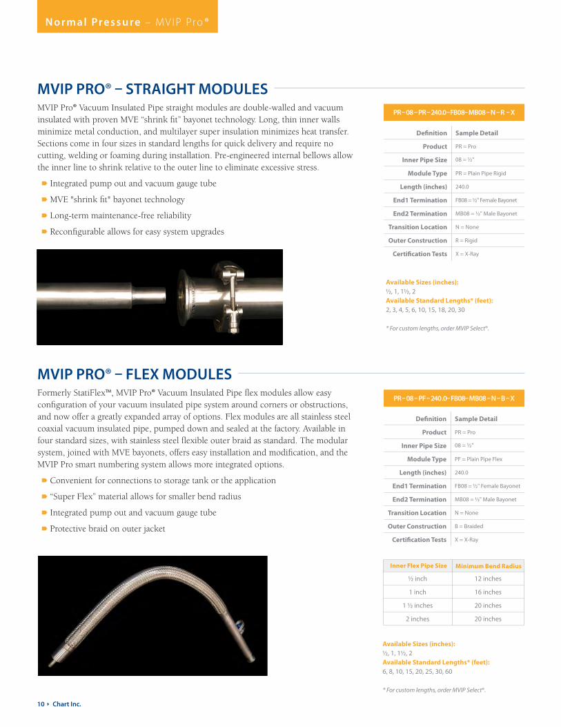
MVIP PRO® – STRAIGHT MODULES
MVIP PRO® – FLEX MODULES
Definition Sample Detail
Product PR = Pro
Inner Pipe Size 08 = ½"
Module Type PR = Plain Pipe Rigid
Length (inches) 240.0
End1 Termination FB08 = ½" Female Bayonet
End2 Termination MB08 = ½" Male Bayonet
Transition Location N = None
Outer Construction R = Rigid
Certification Tests X = X-Ray
Definition Sample Detail
Product PR = Pro
Inner Pipe Size 08 = ½"
Module Type PF = Plain Pipe Flex
Length (inches) 240.0
End1 Termination FB08 = ½" Female Bayonet
End2 Termination MB08 = ½" Male Bayonet
Transition Location N = None
Outer Construction B = Braided
Certification Tests X = X-Ray
PR – 08 – PR – 240.0 –FB08 – MB08 – N – R – X
PR – 08 – PF – 240 .0 – FB08 – MB08 – N – B – X
MVIP Pro® Vacuum Insulated Pipe straight modules are double-walled and vacuum insulated with proven MVE “shrink fit” bayonet technology. Long, thin inner walls minimize metal conduction, and multilayer super insulation minimizes heat transfer. Sections come in four sizes in standard lengths for quick delivery and require no cutting, welding or foaming during installation. Pre-engineered internal bellows allow the inner line to shrink relative to the outer line to eliminate excessive stress.
Integrated pump out and vacuum gauge tube
MVE "shrink fit" bayonet technology
Long-term maintenance-free reliability
Reconfigurable allows for easy system upgrades
Formerly StatiFlex™, MVIP Pro® Vacuum Insulated Pipe flex modules allow easy configuration of your vacuum insulated pipe system around corners or obstructions, and now offer a greatly expanded array of options. Flex modules are all stainless steel coaxial vacuum insulated pipe, pumped down and sealed at the factory. Available in four standard sizes, with stainless steel flexible outer braid as standard. The modular system, joined with MVE bayonets, offers easy installation and modification, and the MVIP Pro smart numbering system allows more integrated options.
Convenient for connections to storage tank or the application
“Super Flex” material allows for smaller bend radius
Integrated pump out and vacuum gauge tube
Protective braid on outer jacket
Available Sizes (inches): ½, 1, 1½, 2Available Standard Lengths* (feet): 2, 3, 4, 5, 6, 10, 15, 18, 20, 30
* For custom lengths, order MVIP Select®.
Available Sizes (inches): ½, 1, 1½, 2Available Standard Lengths* (feet): 6, 8, 10, 15, 20, 25, 30, 60
* For custom lengths, order MVIP Select®.
½ inch 12 inches
1 inch 16 inches
1 ½ inches 20 inches
2 inches 20 inches
Inner Flex Pipe Size Minimum Bend Radius

www.mvippro.com 11
N o r m a l Pre s s u re – M V I P Pro ®
TANK CONNECTION (With Safety Relief Assy)
MULTI OUTLET (2-10) PHASE SEPARATOR
BAYONET CONNECTION Allows for easy field assembly
of pipe sections
FUTURE EXPANSIONOptional tees available with
either capped bayonet or vacuum insulatedliquid shut off valve(as shown)
PIPE BENDS Possible during installation
TRANSFER HOSEVacuum insulated flexible hose (for equipment connections)
GAS TRAP - Reduces liquid losses at end of line when liquid is not flowingVACUUM INSULATED MANIFOLD
(With multiple outlets)
MODULAR TEE(Bayonets all sides)
CryoDoser(Liquid nitrogen dosing unit)
BULK TANK
to eliminate rigid elbows
CRYOVENT (Optional) - Mounted at high point of system. The CRYOVENT keeps the system
continuously vented & wetted with liquid nitrogen
PR – 08 – PR – 240.0 –FB08 – MB08 – N – R – X
PR – 08 – PF – 240 .0 – FB08 – MB08 – N – B – X
TYPICAL MVIP PRO® – FLEX MODULE INSTALLATION
KEY BENEFITS OF FLEX
EASY INSTALLATION &
MODIFICATIONS
Bendable, lightweight, and its plug and play approach facilitates easy installation and allows for on-site layout changes.
FUTURE EXPANSION
Any bayonet joint can accommodate expansion due to its bendable nature.
12 Ì Chart Inc.
N o r m a l Pre s s u re – M V I P Pro ®
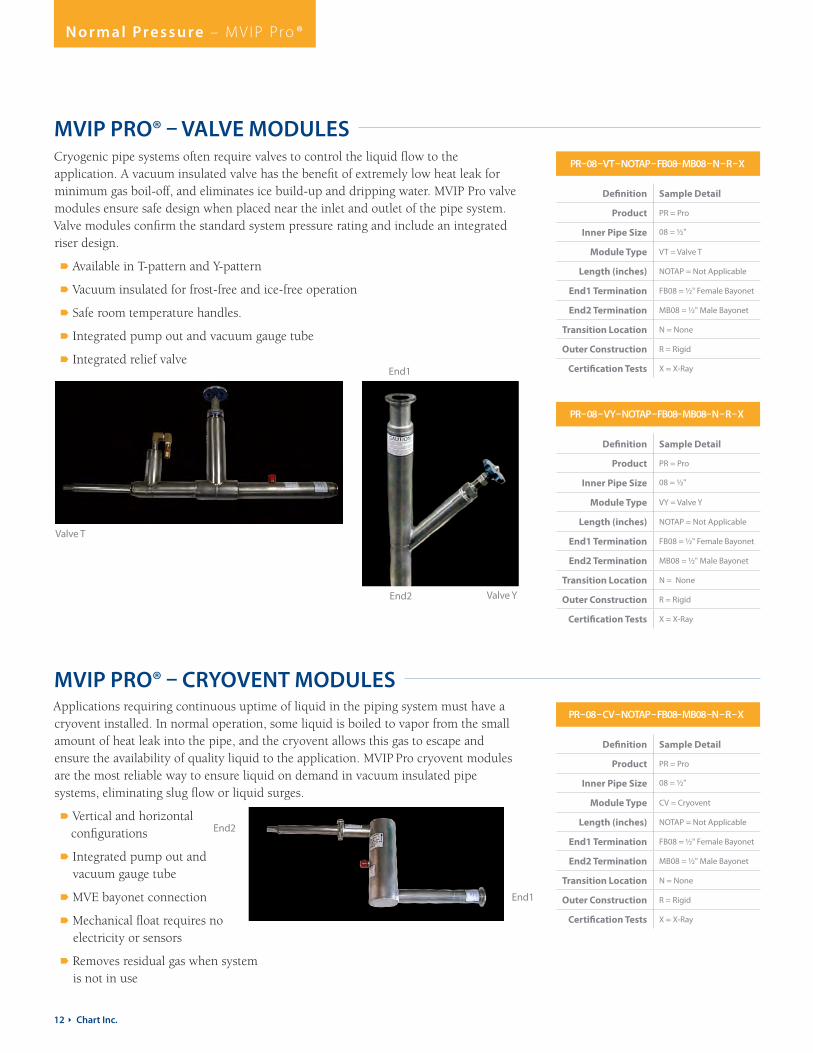
MVIP PRO® – VALVE MODULES
MVIP PRO® – CRYOVENT MODULES
Definition Sample Detail
Product PR = Pro
Inner Pipe Size 08 = ½"
Module Type VT = Valve T
Length (inches) NOTAP = Not Applicable
End1 Termination FB08 = ½" Female Bayonet
End2 Termination MB08 = ½" Male Bayonet
Transition Location N = None
Outer Construction R = Rigid
Certification Tests X = X-Ray
Definition Sample Detail
Product PR = Pro
Inner Pipe Size 08 = ½"
Module Type CV = Cryovent
Length (inches) NOTAP = Not Applicable
End1 Termination FB08 = ½" Female Bayonet
End2 Termination MB08 = ½" Male Bayonet
Transition Location N = None
Outer Construction R = Rigid
Certification Tests X = X-Ray
Definition Sample Detail
Product PR = Pro
Inner Pipe Size 08 = ½"
Module Type VY = Valve Y
Length (inches) NOTAP = Not Applicable
End1 Termination FB08 = ½" Female Bayonet
End2 Termination MB08 = ½" Male Bayonet
Transition Location N = None
Outer Construction R = Rigid
Certification Tests X = X-Ray
PR – 08 – VT – NOTAP – FB08 – MB08 – N – R – X
PR – 08 – CV – NOTAP – FB08 – MB08 –N – R – X
PR – 08 – VY – NOTAP – FB08 – MB08– N – R – X
Cryogenic pipe systems often require valves to control the liquid flow to the application. A vacuum insulated valve has the benefit of extremely low heat leak for minimum gas boil-off, and eliminates ice build-up and dripping water. MVIP Pro valve modules ensure safe design when placed near the inlet and outlet of the pipe system. Valve modules confirm the standard system pressure rating and include an integrated riser design.
Available in T-pattern and Y-pattern
Vacuum insulated for frost-free and ice-free operation
Safe room temperature handles.
Integrated pump out and vacuum gauge tube
Integrated relief valve
Applications requiring continuous uptime of liquid in the piping system must have a cryovent installed. In normal operation, some liquid is boiled to vapor from the small amount of heat leak into the pipe, and the cryovent allows this gas to escape and ensure the availability of quality liquid to the application. MVIP Pro cryovent modules are the most reliable way to ensure liquid on demand in vacuum insulated pipe systems, eliminating slug flow or liquid surges.
Vertical and horizontal configurations
Integrated pump out and vacuum gauge tube
MVE bayonet connection
Mechanical float requires no electricity or sensors
Removes residual gas when system is not in use
Valve T
Valve Y
End1
End2
End2
End1

www.mvippro.com 13
N o r m a l Pre s s u re – M V I P Pro ®
MVIP Pro® Vacuum Insulated Pipe adapter modules offer the lowest heat leak in the industry and are conveniently designed to interface bayonets to threaded connections. All of the common connections are pre-engineered.
Integrated pump out
MVE bayonet
Supports common connections
MVIP PRO® – DROP MODULES OR GAS TRAPS
MVIP PRO® – ADAPTER MODULES
Definition Sample Detail
Product PR = Pro
Inner Pipe Size 08 = ½"
Module Type GT = Gas Trap
Length (inches) NOTAP = Not Applicable
End1 Termination FB08 = ½" Female Bayonet
End2 Termination MP08 = ½" Male Pipe Thread
Transition Location N = None
Outer Construction R = Rigid
Certification Tests X = X-Ray
Definition Sample Detail
Product PR = Pro
Inner Pipe Size 16 = 1"
Module Type AD = Adapter
Length (inches) NOTAP = Not Applicable
End1 Termination MB16 = 1" Male Bayonet
End2 Termination MP16 = 1" Male Pipe Thread
Transition Location N = None
Outer Construction R = Rigid
Certification Tests X = X-Ray
PR – 08 – VT – NOTAP – FB08 – MB08 – N – R – X PR – 08 – GT – NOTAP – FB08 – MP08 –N – R – X
PR – 16– AD – NOTAP– MB16 – MP16 – N – R – X
PR – 08 – VY – NOTAP – FB08 – MB08– N – R – X
MVIP Pro® Vacuum Insulated Pipe drop modules allow the use of non-vacuum jacketed valves, so they provide an economical way to control heat leak and frost to end-use applications. They come in standard lengths for quick delivery.
Pre-engineered
Integrated pump out and vacuum gauge tube
Available in ½" and 1" pipe size
Internal liquid trap
Ends in MPT connection
DID YOU KNOW?MVIP™ from Chart makes it simple to bring a complete solution to your cryogenic system − delivering a reliable, turnkey vacuum insulated piping system that conserves maximum liquid cryogen and results in significant cost savings.
With today’s high energy costs, any new cryogenic system should be evaluated and designed from a complete system perspective to obtain the most efficient system for the long-term lowest cost of operation. Existing cryogenic systems should be reviewed for opportunities to improve system efficiency and lower operating costs.
Chart makes it simple. Talk to us today.
End2End1
End1
End2
14 Ì Chart Inc.
N o r m a l Pre s s u re – M V I P Pro ®
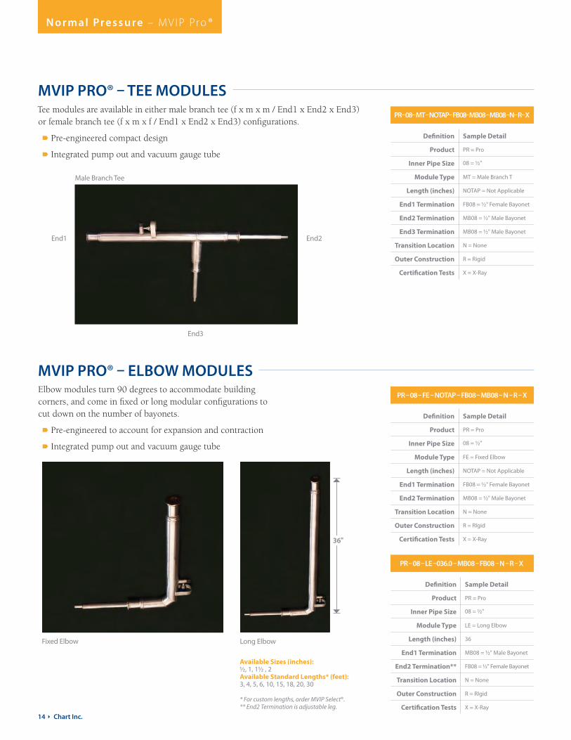
MVIP PRO® – TEE MODULES
Definition Sample Detail
Product PR = Pro
Inner Pipe Size 08 = ½"
Module Type MT = Male Branch T
Length (inches) NOTAP = Not Applicable
End1 Termination FB08 = ½" Female Bayonet
End2 Termination MB08 = ½" Male Bayonet
End3 Termination MB08 = ½" Male Bayonet
Transition Location N = None
Outer Construction R = Rigid
Certification Tests X = X-Ray
PR – 08 – MT – NOTAP– FB08 – MB08 – MB08 –N– R– X
MVIP PRO® – ELBOW MODULES
Definition Sample Detail
Product PR = Pro
Inner Pipe Size 08 = ½"
Module Type FE = Fixed Elbow
Length (inches) NOTAP = Not Applicable
End1 Termination FB08 = ½" Female Bayonet
End2 Termination MB08 = ½" Male Bayonet
Transition Location N = None
Outer Construction R = RIgid
Certification Tests X = X-Ray
PR – 08 – FE – NOTAP – FB08 – MB08 – N – R – X
Tee modules are available in either male branch tee (f x m x m / End1 x End2 x End3) or female branch tee (f x m x f / End1 x End2 x End3) configurations.
Pre-engineered compact design
Integrated pump out and vacuum gauge tube
Elbow modules turn 90 degrees to accommodate building corners, and come in fixed or long modular configurations to cut down on the number of bayonets.
Pre-engineered to account for expansion and contraction
Integrated pump out and vacuum gauge tube
Male Branch Tee
End1 End2
End3
Fixed Elbow Long Elbow
Definition Sample Detail
Product PR = Pro
Inner Pipe Size 08 = ½"
Module Type LE = Long Elbow
Length (inches) 36
End1 Termination MB08 = ½" Male Bayonet
End2 Termination** FB08 = ½" Female Bayonet
Transition Location N = None
Outer Construction R = RIgid
Certification Tests X = X-Ray
PR – 08 – LE –036.0 – MB08 – FB08 – N – R – X
Available Sizes (inches): ½, 1, 1½ , 2Available Standard Lengths* (feet): 3, 4, 5, 6, 10, 15, 18, 20, 30
* For custom lengths, order MVIP Select®.** End2 Termination is adjustable leg.
36"

www.mvippro.com 15
N o r m a l Pre s s u re – M V I P Pro ®
The following table can be used as an initial estimate of required pipe size. It is strongly suggested that a detailed analysis of the actual expected pressure drop be considered with respect to the allowable pressure drop for the process of interest.
EQUIVALENT LENGTH OF PIPE (FT)
GPM 50 100 150 200 250 300 350 400 450 500
2 ½" ½" ½" ½" ½" ½" ½" ½" ½" ½"
4 ½" ½" ½" ½" ½" ½" ½" 1" 1" 1"
6 ½" ½" ½" 1" 1" 1" 1" 1" 1" 1"
8 ½" 1" 1" 1" 1" 1" 1" 1" 1" 1"
10 ½" 1" 1" 1" 1" 1" 1" 1" 1" 1"
15 1" 1" 1" 1" 1" 1" 1" 1" 2" 2"
20 1" 1" 1" 1" 2" 2" 2" 2" 2" 2"
25 1" 1" 2" 2" 2" 2" 2" 2" 2" 2"
30 1" 1" 2" 2" 2" 2" 2" 2" 2" 2" Notes: 1. This table is intended to be used as a guide only and should not be substituted for a complete analysis. 2. Suggested sizes assume an allowable pressure drop of 10 psi. 3. Equivalent length of pipe (ft) = Length of pipe + (5 x # of elbows and tees) + (40 x # of valves) Example: System requires 10 GPM through a pipe system that has 130 feet of pipe, 4 elbows, 2 tees and 1 valve. Equivalent length of pipe = 130 + 5 x (4 +2) + 40 x (1) = 200. Table look-up with 10 GPM and 200 ft suggested pipe size is 1”. 4. Add 1 psi pressure drop for every 3 feet of vertical rise with LN2.
WEIGHT GAS LIQUID
Pounds (Lb)
Kilograms (Kg) Cubic Feet (SCF)
Cubic Meters (Nm3)
Gallons (Gal)
Liters (L)
1 Pound 1.0 0.4536 13.803 0.3627 0.1481 0.5606
1 Kilogram 2.205 1.0 30.42 0.7996 0.3262 1.2349
1 SCF Gas 0.07245 0.03286 1.0 0.02628 0.01074 0.04065
1 Nm3 Gas 2.757 1.2506 38.04 1.0 0.4080 1.5443
1 Gal Liquid 6.745 3.060 93.11 2.447 1.0 3.785
1 L Liquid 1.782 0.8083 24.60 0.6464 0.2642 1.0SCF (Standard Cubic Feet) gas measured at 1 atmosphere and 70°F. Nm3 (normal cubic meter) measured at 1 atmosphere and 0°C.Liquid measured at 1 atmosphere and boiling temperature. All values rounded to nearest 4/5 significant numbers.
AT ATMOSPHERIC PRESSURE: Boiling Temperature: -320°F (-196°C) Heat of Vaporization: 85.6 BTU/lb (198.8 KJ/Kg) Liquid Density: 6.745 lb/gal (0.806 Kg/L)
MVIP™ SIZING CHART
EQUIVALENT LENGTH OF PIPE (FT)
LIQUID NITROGEN PROPERTIES
MVIP PRO® TECHNICAL INFORMATION
INNER PIPE OUTER PIPE
NOMINAL DIAMETER ACTUAL FLOW DIAMETER NOMINAL DIAMETER ACTUAL OUTSIDE DIAMETER
½" 0.710" 2" 2.375"
1" 1.185" 3" 3.5"
1½" 1.770" 3½" 4.0"
2" 2.245" 3½" 4.0"
3" 3.334" 5" 5.563"

16 Ì Chart Inc.
H i g h Pre s s u re – M V I P P Y T H O N
www.mvippro.com 17
H i g h Pre s s u re – M V I P P Y T H O N ®
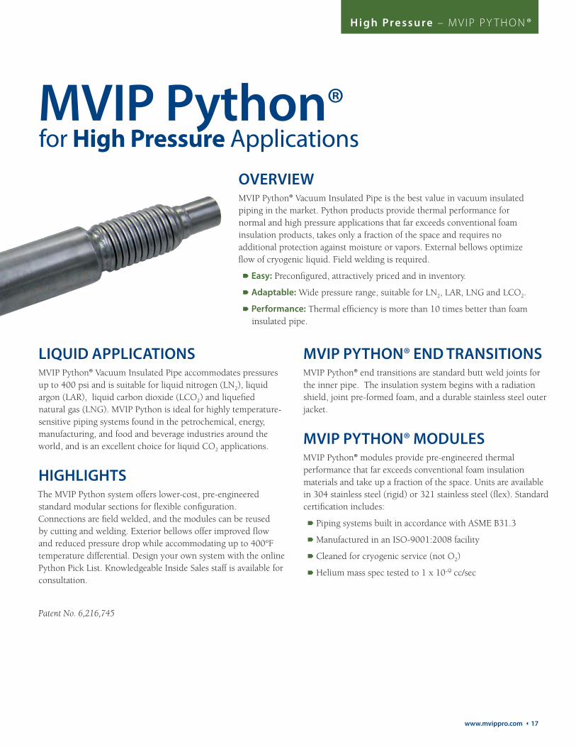
for High Pressure ApplicationsMVIP Python®
OVERVIEWMVIP Python® Vacuum Insulated Pipe is the best value in vacuum insulated piping in the market. Python products provide thermal performance for normal and high pressure applications that far exceeds conventional foam insulation products, takes only a fraction of the space and requires no additional protection against moisture or vapors. External bellows optimize flow of cryogenic liquid. Field welding is required.
Easy: Preconfigured, attractively priced and in inventory.
Adaptable: Wide pressure range, suitable for LN2, LAR, LNG and LCO2.
Performance: Thermal efficiency is more than 10 times better than foam insulated pipe.
LIQUID APPLICATIONSMVIP Python® Vacuum Insulated Pipe accommodates pressures up to 400 psi and is suitable for liquid nitrogen (LN2), liquid argon (LAR), liquid carbon dioxide (LCO2) and liquefied natural gas (LNG). MVIP Python is ideal for highly temperature-sensitive piping systems found in the petrochemical, energy, manufacturing, and food and beverage industries around the world, and is an excellent choice for liquid CO2 applications.
HIGHLIGHTSThe MVIP Python system offers lower-cost, pre-engineered standard modular sections for flexible configuration. Connections are field welded, and the modules can be reused by cutting and welding. Exterior bellows offer improved flow and reduced pressure drop while accommodating up to 400°F temperature differential. Design your own system with the online Python Pick List. Knowledgeable Inside Sales staff is available for consultation.
Patent No. 6,216,745
MVIP PYTHON® END TRANSITIONSMVIP Python® end transitions are standard butt weld joints for the inner pipe. The insulation system begins with a radiation shield, joint pre-formed foam, and a durable stainless steel outer jacket.
MVIP PYTHON® MODULESMVIP Python® modules provide pre-engineered thermal performance that far exceeds conventional foam insulation materials and take up a fraction of the space. Units are available in 304 stainless steel (rigid) or 321 stainless steel (flex). Standard certification includes:
Piping systems built in accordance with ASME B31.3
Manufactured in an ISO-9001:2008 facility
Cleaned for cryogenic service (not O2)
Helium mass spec tested to 1 x 10⁻⁹ cc/sec

18 Ì Chart Inc.
H i g h Pre s s u re – M V I P P Y T H O N ®
MVIP PYTHON® – STRAIGHT MODULES
MVIP PYTHON® – FLEX MODULES
Definition Sample Detail
Product PY = Python
Inner Pipe Size 16 = 1"
Module Type PR = Plain Pipe Rigid
Length (inches) 60
End1 Termination PY16 = 1" Python
End2 Termination PY16 = 1" Python
Transition Location N = None
Outer Construction R = Rigid
Certification Tests X = X-Ray
Definition Sample Detail
Product PY = Python
Inner Pipe Size 16 = 1"
Module Type PF = Plain Pipe Flex
Length (inches) 102
End1 Termination PY16 = 1" Python
End2 Termination PY16 = 1" Python
Transition Location N = None
Outer Construction C = Convoluted
Certification Tests X = X-Ray
PY – 16– PR – 060.0 – PY16 – PY16 – N – R – X
PY – 16 – PF – 102.0 – PY16 – PY16 – N – C– X
Integrated internal supports
Low conductivity spacers and ends
Standard lengths for quick delivery
Integrated pump out
Convenient for connections to storage or the application
Integrated pump out
Convoluted outer jacket
Standard lengths for quick delivery
MVIP Python® Vacuum Insulated Pipe straight modules are double-wall vacuum insulated. Multilayered super insulation minimizes radiation heat transfer. Sections come in standard lengths for quick delivery. Pre-engineered external bellows allow the inner line to shrink relative to the outer line without creating excessive stress, while maintaining a smooth inner line for most efficient flow and lowest possible pressure
MVIP Python® Vacuum Insulated Pipe flex modules allow easy configuration of your vacuum insulated pipe system around corners or obstructions, and now offer a greatly expanded array of options. Flex modules are all stainless steel coaxial vacuum insulated pipe, pumped down and sealed at the factory. The MVIP smart numbering system allows more integrated options.
Available Sizes (inches): ½, 1, 2, 3Available Standard Lengths* (feet): 2 - 20 in 1' increments
* For custom lengths, order MVIP Select®.
1 8½
2 9
3 9
Available Sizes (inches)
Available Standard Lengths* (feet)
* For custom lengths, order MVIP Select®.
www.mvippro.com 19
H i g h Pre s s u re – M V I P P Y T H O N ®
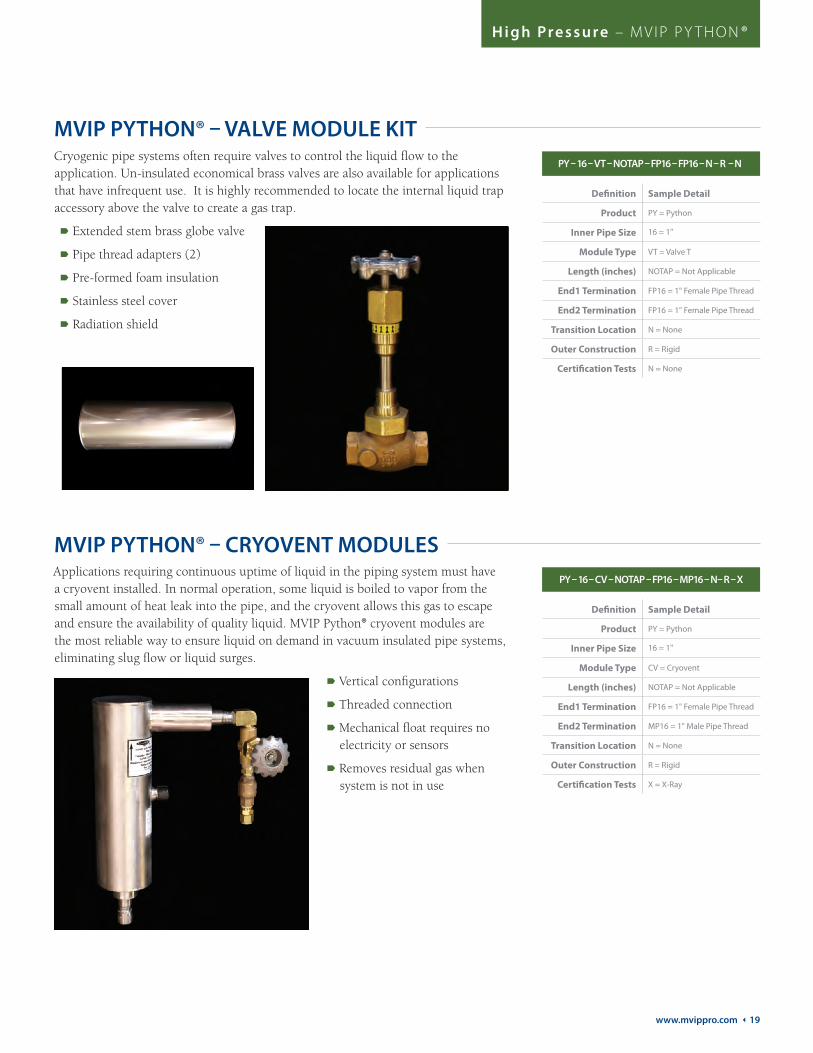
MVIP PYTHON® – VALVE MODULE KIT
Definition Sample Detail
Product PY = Python
Inner Pipe Size 16 = 1"
Module Type VT = Valve T
Length (inches) NOTAP = Not Applicable
End1 Termination FP16 = 1" Female Pipe Thread
End2 Termination FP16 = 1" Female Pipe Thread
Transition Location N = None
Outer Construction R = Rigid
Certification Tests N = None
PY – 16 – VT – NOTAP – FP16 – FP16 – N – R – N
MVIP PYTHON® – CRYOVENT MODULES
Definition Sample Detail
Product PY = Python
Inner Pipe Size 16 = 1"
Module Type CV = Cryovent
Length (inches) NOTAP = Not Applicable
End1 Termination FP16 = 1" Female Pipe Thread
End2 Termination MP16 = 1" Male Pipe Thread
Transition Location N = None
Outer Construction R = Rigid
Certification Tests X = X-Ray
PY – 16 – CV – NOTAP – FP16 – MP16 – N– R – X
Cryogenic pipe systems often require valves to control the liquid flow to the application. Un-insulated economical brass valves are also available for applications that have infrequent use. It is highly recommended to locate the internal liquid trap accessory above the valve to create a gas trap.
Extended stem brass globe valve
Pipe thread adapters (2)
Pre-formed foam insulation
Stainless steel cover
Radiation shield
Applications requiring continuous uptime of liquid in the piping system must have a cryovent installed. In normal operation, some liquid is boiled to vapor from the small amount of heat leak into the pipe, and the cryovent allows this gas to escape and ensure the availability of quality liquid. MVIP Python® cryovent modules are the most reliable way to ensure liquid on demand in vacuum insulated pipe systems, eliminating slug flow or liquid surges.
Vertical configurations
Threaded connection
Mechanical float requires no electricity or sensors
Removes residual gas when system is not in use

20 Ì Chart Inc.
H i g h Pre s s u re – M V I P P Y T H O N ®
MVIP PYTHON® – ADAPTER MODULES MVIP Python® Vacuum Insulated Pipe adapter modules are designed to interface with most systems.
Supports common connections
Stainless steel construction
Sized to weld directly to Python®
Definition Sample Detail
Product PY = Python
Inner Pipe Size 16 = 1"
Module Type AD = Adapter
Length (inches) NOTAP = Not Applicable
End1 Termination BW16 = 1" Butt Weld
End2 Termination MP16 = 1" Male Pipe Thread
Transition Location N = None
Outer Construction R = Rigid
Certification Tests N = None
PY – 16 – AD – NOTAP – BW 16 – MP16 – N – R – N
DID YOU KNOW?Due to the extreme temperatures involved in cryogenics, heat transfers very quickly at any location that is not extremely well insulated. One of the worst places, and unfortunately the most common, for this to occur is the connection of the piping system to the liquid supply tank. If this connection is not fully vacuum insulated, the heat transferred into the system at this point can be greater than the heat leak in the entire rest of the pipe system.
CHART CANChart will engineer ANY adapter for ANY system … even a competitor’s system.
Chart is the expert on cryogenic storage and delivery systems. We know tanks, bulk and MicroBulk storage, LNG systems and more, inside and out. Chart’s cryogenic engineering expertise and custom piping capabilities mean that we can create the adapters you need, no matter what system you are using.
MVIP PYTHON® TECHNICAL INFORMATION
INNER PIPE OUTER PIPEOUTER DIAMETER INSULATION KIT
NOMINAL DIAMETER ACTUAL FLOW DIAMETER NOMINAL DIAMETER ACTUAL OUTSIDE DIAMETER
1" 1.185" 2" 2.375" 6.75"
2" 2.245" 3" 3.5" 8.0"
3" 3.334" 5" 5.563" 9.5"

www.mvippro.com 21
H i g h Pre s s u re – M V I P P Y T H O N ®
MVIP PYTHON® – TEE MODULE KIT
MVIP PYTHON® – ELBOW MODULE KIT
Definition Sample Detail
Product PY = Python
Inner Pipe Size 16 = 1"
Module Type TK = Tee Kit
Length (inches) NOTAP = Not Applicable
End1 Termination BW16 = 1" Butt Weld
End2 Termination BW16 = 1" Butt Weld
Transition Location N = None
Outer Construction R = Rigid
Certification Tests N = None
PY – 16 – TK – NOTAP – BW16 – BW16 – N – R – N
Definition Sample Detail
Product PY = Python
Inner Pipe Size 16 = 1"
Module Type EK = Elbow Kit
Length (inches) NOTAP = Not Applicable
End1 Termination BW16 = 1" Butt Weld
End2 Termination BW16 = 1" Butt Weld
Transition Location N = None
Outer Construction R = Rigid
Certification Tests N = None
PY – 16 – EK – NOTAP– BW16 – BW16 – N – R – N
MVIP Python® Vacuum Insulated Pipe tee modules accommodate branches or runs.
Pre-engineered
Stainless steel inner tee
Pre-formed foam insulation
Stainless steel cover
Radiation shield
Elbow modules turn 90 degrees to accommodate building corners.
Pre-engineered
Stainless steel inner elbow
Pre-formed foam insulation
Stainless steel cover
Radiation shield
MVIP PYTHON® – STRAIGHT INSULATION KIT
Definition Sample Detail
Product PY = Python
Inner Pipe Size 16 = 1"
Module Type SK = Straight Kit
Length (inches) NOTAP = Not Applicable
End1 Termination BW16 = 1" Butt Weld
End2 Termination BW16 = 1" Butt Weld
Transition Location N = None
Outer Construction R = Rigid
Certification Tests N = None
PY – 16 – SK – NOTAP – BW16 – BW16 – N – R – NStraight modules accommodate straight sections.
Pre-engineered
Pre-formed foam insulation
Stainless steel cover
Radiation shield

22 Ì Chart Inc.
Cu s t o m E n g i n e e re d – M V I P S E L E C T

www.mvippro.com 23
Cu s t o m E n g i n e e re d – M V I P S E L E C T ®
Custom Engineered ApplicationsMVIP Select®OVERVIEWTo meet complex application requirements, MVIP Select® offers custom engineered, built-to-order vacuum insulated pipe systems. Chart’s experienced staff is available to guide you through design and price trade-offs to create your best total value while meeting precise system requirements.
Ultimate Flexibility: Chart’s five design platforms can be configured to meet your budget, performance and installation parameters.
Capable: From molecular beam epitaxy to deep space temperature simulation, Chart vacuum insulated pipe is designed to meet your application needs.
High Performance: Chart’s mantra is to protect the molecule by offering the ultimate radiation, convection and conduction performance available.
Chart’s staff can design, build and install cryogenic system solutions of all levels of complexity. Sales engineers, field technicians, customer service representatives, project managers, project engineers, staff engineers and designers are at your service to create the optimal system to meet your unique specifications and installation needs.
HIGHLIGHTSWith MVIP Select® Vacuum Insulated Pipe, choose from five major pipe design platforms in stainless steel or Invar:
Invar®
Internal bellows
External bellows
Helium Lines
Custom Python®
Invar offers the ultimate solution for the most demanding applications. Special Invar material is used for the inner pipe providing an extremely low coefficient of thermal expansion, eliminating the need for flexible bellows. This allows for a higher system design pressure.
ADDITIONAL FEATURES AND OPTIONS Leverage major CAD platforms (ProE and AutoCAD)
Fully traceable materials
Special code approval processes
Third party inspections
Quality control processes
Internal pressure load analysis
External load analysis
Combined load analysis
Thermal expansion analysis
Pressure drop analysis capability
Heat-leak analysis capability
Cold shock testing capability
Liquid Dye Penetreant testing capability
Pressure / Flow Testing
X-ray
Finite Element Analysis
O2 Clean
Field joint connections
High shine finish for clean room, food or beverage applications
24 Ì Chart Inc.
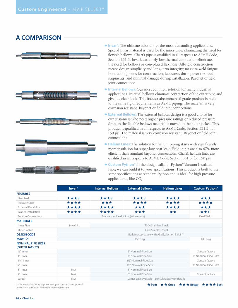
Cu s t o m E n g i n e e re d – M V I P S E L E C T ®
A COMPARISON Invar®: The ultimate solution for the most demanding applications.
Special Invar material is used for the inner pipe, eliminating the need for flexible bellows. Chart’s pipe is qualified in all respects to ASME Code, Section B31.3. Invar’s extremely low thermal contraction eliminates the need for bellows or convoluted flex hose. All-rigid construction means design simplicity and long-term integrity; no extra weld fatigue from adding items for construction; less stress during over-the-road shipments; and minimal damage during installation. Bayonet or field joint connections.
Internal Bellows: Our most common solution for many industrial applications. Internal bellows eliminate contraction of the outer pipe and give it a clean look. This industrial/commercial grade product is built to the same rigid requirements as ASME piping. The material is very corrosion resistant. Bayonet or field joint connections.
External Bellows: The external bellows design is a good choice for our customers who need higher pressure ratings or reduced pressure drop, as the flexible bellows material is moved to the outer jacket. This product is qualified in all respects to ASME Code, Section B31.3, for 150 psi. The material is very corrosion resistant. Bayonet or field joint connections.
Helium Lines: The solution for helium piping starts with significantly more insulation for super-low heat leak. Field joints are also 67% more efficient than standard bayonet connections. Chart’s helium lines are qualified in all respects to ASME Code, Section B31.3, for 150 psi.
Custom Python®: If the design calls for Python® Vacuum Insulated Pipe, we can build it to your specifications. This product is built to the same specifications as standard Python and is ideal for high pressure applications, like CO2.
Invar® Internal Bellows External Bellows Helium Lines Custom Python®
FEATURES
Heat Leak
Pressure Drop
External Durability
Ease of Installation
Section Connections Bayonets or Field Joints (w/ vacuum) Field Welds
MATERIALS
Inner Pipe Invar36 T304 Stainless Steel
Outer Jacket T304 Stainless Steel
DESIGN CODE Built in accordance with ASME, Section B31.3 (1)
MAWP (2) 150 psig 400 psig
NOMINAL PIPE SIZES (OUTER JACKET) ½" Inner 2" Nominal Pipe Size Consult factory
1" Inner 3" Nominal Pipe Size 2" Nominal Pipe Size 1½" Inner 3½" Nominal Pipe Size Consult factory
2" Inner 3½" Nominal Pipe Size 3" Nominal Pipe Size 3" Inner N/A 5" Nominal Pipe Size
4" Inner N/A 6" Nominal Pipe Size Consult factory
Larger N/A Larger sizes available – consult factory for details
Poor Good Better Best(1) Code required X-ray or pneumatic pressure tests are optional(2) MAWP = Maximum Allowable Working Pressure

www.mvippro.com 25
Cu s t o m E n g i n e e re d – M V I P S E L E C T ®
BY THE NUMBERSOperating costs
Based on vendor published studies with LN
2, total annual operating costs
using foam insulated pipe are more than eight times the operating costs using vacuum insulated pipe.
YOUR SYSTEM, YOUR WAYHow many ways can you configure your own modular vacuum insulated piping system? It’s all up to you. Do it your way. MVIP™ Vacuum Insulated Pipe from Chart makes it easy.
Chart Solutions:
When evaluating a cryogenic system, companies tend to focus on the large portions of the system. It’s easy to realize the importance of the insulation system on a 6,000 gallon tank, or 150 feet of pipe. Unfortunately, many facilities tend to ignore details like the connection of the pipe system to the storage tank, or to the end use equipment.
Heat influx at these points can cause local boiling and two-phase liquid gas flow, which in turn creates significantly higher pressure drops through the pipe system, irregular liquid delivery, warmer liquid, increased wear on soft goods such as valve seats, and other system complications. Not only does liquid gas evaporate at poorly insulated connections, resulting in product losses, but ice accumulation on a non-vacuum insulated outlet system will also encase any surrounding piping, valves or circuits, increasing the likelihood of maintenance problems and a possible shutdown.
Poorly insulated connections often occur when one firm owns the bulk tank while another firm owns the pipe system, and neither wants to take ownership of the interface or connection. As a result, the connection is made in a short period of time with “good enough” materials, rather than being carefully selected and integrally designed for optimal efficiency.
Make sure you are thinking about your whole system. Use MVIP vacuum insulated withdrawals and connectors to ensure that your entire delivery system benefits from the same efficient insulation system that’s used to insulate your storage tank and pipes.
Chart can help. Talk to us today.
Problem: Weak links in your cryogenic supply system.
Solution: MVIP™ connections from Chart.

26 Ì Chart Inc.
Acce s s o r i e s
AccessoriesOVERVIEWMVIP™ Vacuum Insulated Pipe accessories add valuable options and functionality to your cryogenic liquid delivery system. Most of the accessories shown here are compatible with MVIP Pro®, MVIP Python® and MVIP Select® systems.
PHASE SEPARATOR
ADJUSTABLE PRESSURE PHASE SEPARATOR – APPS
Phase Separators are stainless steel, vacuum insulated vessels designed to store liquid nitrogen under atmospheric pressure. They are used in specialized applications requiring extremely high quality, low pressure liquid nitrogen on demand. Typical applications include both direct feed or closed loop systems. The Phase Separator provides an economical means to ensure single phase flow for applications like liquid nitrogen dosers.
Electronically controlled liquid level
Ensures atmospheric pressure and liquid flow
The APPS 160 offers a convenient method of providing low-pressure liquid to an installation that is supplied from a bulk tank at higher pressure, without the cost of installing two bulk tanks.
Tighter pressure control for the lower pressure liquid application
Adjustable outlet pressure ranges
Working capacity of 160 liters
Bayonet outlet connection is standard

www.mvippro.com 27
Acce s s o r i e s
CRYOVENTS & HEATERS
OXYGEN MONITOR
Chart’s cryovents are installed to enhance the performance of the pipe system. In normal operation, some liquid is boiled to vapor from the small amount of heat leak into the pipe, and the cryovent allows this gas to escape. Applications requiring continuous up-time of liquid in the piping system must have a cryovent installed to ensure the availability of quality liquid. The result is more efficient operation of the liquid supply.
Available in a wide variety of sizes and configurations, including vacuum insulated exhaust connection to reduce ice build-up from the cold gas
Electric heater options also available as another solution to eliminate exhaust ice build-up
Available with pipe thread or bayonet inlets and outlets for system installation flexibility
The Toxgard II O2 monitor detects toxic gases, combustible gases or oxygen deficiency. The monitor is ideal for areas where harmful gases are stored or where a build-up of harmful gases may threaten worker or patient safety. Easy to install and operate.
O2 monitor can safely and accurately monitor safe levels of oxygen
Large LED display
Multiple alarm modes
Automatic calibration
Battery backup allows the monitor to detect O2 levels for up to 24 hours in the event of a loss of power
VACUUM INSULATED WITHDRAWAL Vacuum Insulated Liquid Withdrawal is designed for applications that require the transfer of high quality, cold, low-pressure liquid from bulk or MicroBulk storage. Providing quality low-pressure liquid at the point of use requires minimal heat leak throughout the entire piping system, including key plumbing components.
Eliminates ice buildup and sweating
Substantial long term savings in liquid use
Provides higher quality, colder liquid at the point of use

28 Ì Chart Inc.
Acce s s o r i e s
C-FLEX VACUUM INSULATED TRANSFER HOSES Super flexible vacuum insulated liquid nitrogen transfer hoses are used in a wide
variety of applications including tool connections and custom OEM applications.
The coaxial bellowed construction allows for optimal flexibility. The use of
lightweight stainless steel reduces cool-down loss to an absolute minimum.
C-Flex hoses are protected by a stainless steel spiral wrap or a braided outer cover.
Custom Manifolds Available – utilize vacuum insulated tees, elbows, bayonets, and valves to custom tailor the configuration (Consult factory)
High Pressure Requirements – optional inner braid for higher pressure applications (Consult factory)
Minimal Cool Down & Steady State Losses – compared to standard non-insulated transfer hoses
Integrated pump out
Length (in / ft) 48" / 4' 72" / 6' 96" / 8' 120" / 10' 144" / 12' 192" / 16' 240" / 20'¼" Inner Diameter (ID) 1.6 gpm 1.4 gpm 1.2 gpm 1.1 gpm 1 gpm 0.8 gpm 0.7 gpm3 8" Inner Diameter (ID) 6.0 gpm 4.8 gpm 4.1 gpm 3.6 gpm 3 gpm 2.8 gpm 2.6 gpm
½" Inner Diameter (ID) 11.4 gpm 9.0 gpm 7.6 gpm 6.8 gpm 6 gpm 5.2 gpm 4.4 gpm
C-FLEX TECHNICAL INFORMATION
C-FLEX FLOW DATA 22 psi LN2 Source; 4 psi Pressure Drop (max)
SMART NUMBERING SYSTEM
/
OverallLength
Outer Wrap
End1 Termination
End2 Termination
– –
S = SpiralB = Braided
XX = ft
EVACUATION PORT
BAYONET CONNECTIONS)
INNER ST
OUTER STAINLESS STEEL BELLOWS
BRAIDED COVER
AINLESS STEEL BELLOWS
MPT (MALE PIPE THREAD)
VACUUM SPACE BETWEEN INNER AND OUTER BELLOWS CONTAINS MULTI LAYERS OF SUPER INSULATION MATERIALS
1/2" (ALSO AVAILABLE w/
Inner FlexDiameter
04 = ¼"06 = 3 8"08 = ½"
/8SE = ½" SAE 45 Female Flare4PT = ¼" MPT6PT = 3 8" MPT8PT = ½" MPT8T = ½" Smooth Tube10PT = 5 8" MPT20PT = 1¼" MPT6F = 625 Female Bayonet6M = 625 Male BayonetNONE = NONE
/
/
Model 04S 06S 08S 08BInner Diameter (ID) 1/4" (6.3 mm) 3/8" (9.5 mm) 1/2" (12.7 mm) 1/2" (12.7 mm)
Outer Diameter (OD) 1.25" (31.75 mm) 1.65" (41.91 mm) 1.90" (48.26 mm) 1.80" (45.72 mm)
Minimum Flexible Bend Radius 7" (177 mm) 8" (203 mm) 10" (254 mm) 10" (254 mm)
Minimum Static Bend Radius 5" (127 mm) 6" (152 mm) 8" (203 mm) 7" (177 mm)
Maximum Operating Pressure 150 psi (10.3 bar) 150 psi (10.3 bar) 150 psi (10.3 bar) 150 psi (10.3 bar)
S: Spiral wrap outer covering B: Braided outer coveringC-Flex hoses are available in standard or custom lengths up to 60 feet.

www.mvippro.com 29
Contact UsWhether using our innovative Modulator™ MVIP Ordering Software or working directly with our experienced engineering staff, Chart offers the expertise and experience you need to complete your VIP project.
Ready to get started? Talk to us today.
Chart Inc. 407 Seventh Street NW New Prague, MN 56071 952-758-4484
Chart’s expert field service staff is just a phone call away to assist with start-up services, testing and repairs. Field service technicians are fully trained to handle on-site repair and maintenance requirements, and can be dispatched promptly.
Our service specialists can repair almost any type and make of cryogenic equipment on site and install all types of vacuum insulated pipe. They can also conduct helium mass spectrometer leak testing and vacuum loss testing. Convenient on-site repairs come with the assurance of Chart’s first class craftsmanship.
Contact Chart for single-source accountability and timely service from a team that knows the Chart product line inside and out.
Call: 1-800-400-4683 | Worldwide: 1-952-758-4484 Email [email protected]
SERVICE AND
SUPPORT

Phone 888-877-3093 | Worldwide 952-758-4484 | Fax 952-758-8293
Chart Inc. | 407 Seventh Street NW | New Prague, MN 56071
www.chartindustries.com | www.MVIPpro.com
©2016 Chart Inc. P/N 20661575


