
Synthesis of MWNTs, DWNTs and SWNTs Buckypaper using Triton x-100.
And comparing their mechanical ,electrical and physical properties (report submitted in (partial) fulfilment of the requirements for the completion ofChem991)
by
Awad Nasser Albalwi
School of Chemistry
University of Wollongong
2
Table of Contents Page.N0#
COVER
CONTENTS 2-3
ABSTRACT 4
1 Introduction 4
1.1 Carbon Nanotubes & bukypaper 4-5
1.2 Carbon Nanotube Synthesis 6
1.2.1 Arc-discharge and laser ablation methods: 6
1.2.2 Chemical Vapor Deposition 7
1.3 Applications of Carbon Nanotubes 8
1.3.1 Electronic 8
1.3.2 Energy 9
1.3.3 Sensors 9
1.4 Aim 11
2.0 Experimental: 12
2.1 Solution Preparation 12
2.2 Characterisation of the Solution 13
2.3 Preparation of buckypaper 13
2.4 Characterisation of the Buckypaper 14
2.4.1 Conductivity 14
2.4.2 Mechanical Testing 15

3
2.4.3 Scanning Electron Microscopy 16
3.0 RESULTS AND DISCUSSION 16
3.1 An effect of sonication time on the Dispersion Stability
& Microscopy Testing
16
3.2 Absorbance Analysis
20
3.3 Conductivity Analysis 20
3.4 Mechanical Analysis 23
3.5 SEM Images Analysis 24
4 Conclusions 28
5 Acknowledgements 28
6 REFERENCES 29

4
Abstract
In this study buckypaper of MWNTs, DWNTs and SWNT have been
synthesised using filtration of carbon nanotubes dispersed in 1% TritonX 100
as solvents. Dispersions were generated by pulse sonication of each single
wall carbon nanotubes (SWNTs) , Double wall carbon nanotubes (DWNTs)
and Multi wall carbon nanotubes in TritonX solvent. Fist, sonication times
were investigated for these CNTs to determine the optimum conditions for
generating stable dispersions of carbon nanotubes. It was found that optimal
dispersions could be generated using Trion X-100 solvent with all these
carbon nanotube by using 30minute periods of pulse sonication. The Three
buckypapers of MWNTs, DWNTs and SWNTs were produced by filtering
dispersions of carbon nanotubes which had undergone 30 minutes of pulse
sonication in TritonX100. Conductivity and measurements of the three
buckypaper (SWNT,DWNT&MWNT) samples yielded average values of 14.24
, 23 and 19 Scm-1 respectively. Mechanical measurements were determined
successfully . Homogeneity in the produced buckypapers were investigated
confirming by scanning electron microscopy .
1. Introduction
1.1 Carbon Nanotube & bukypaper
Carbon nano tube has acted as a front runner for the whole field of
nanotechnology, attracting much attention from the industries and
academic community. Carbon nanotubes actually emerge as the leading
material in the nanotechnology revolution. The unique morphology, dimensions
and defects of Carbon nanotubes are distinguished from the other carbon
forms.

5
There are essentially two categories of nanotubes that are prevalently used
today. The multiwall carbon nanotubes (MWNTs), that were catalytically
grown (by chemical vapor deposition; CVD). The dimensions of these were
typically several tens of nanometers in diameter, but occasionally smaller
structures including single-layer tubular structures were also observed. In
recent times they have shown the most promising appearance to the
commercial marketplace [8]. The single-wall nanotubes (SWNTs) in 199ed3
was prducby the NEC and IBM groups also by catalytic vapor deposition to
make single-layer tubular structures of graphene with diameters as small as
1 nm.
Fig.1 CNTs structures for SWNTs,DWNTs and MWNTs 6.
Buckypapers
Nanotubes have high tendency towards self aggregation due to strong Van
der waals forces. This property makes entanglement and aggregation of
nanotube easy. Entangled assemblies of carbon nano tubes that are prepared
by dispersion in solution and filtration with the help of ultrasonication are
called buckypaper. This assembly makes the handling of nanotubes easier for
dopping or raman spetrocopy.Potential applications of buckypaper include ,
SWNTs,One cylinder d = 0.4 – 3 nm DWNTs,Two cylinders d = 2.3 – 3.3 nm
MWNTs,Multiple cylinders d = 1.4 – 100 nm

6
radio frequency filtter,actuators, cold field emission cathode, Li-ion
batteries,solar cell.[8,9]
1.2 Carbon Nanotube Synthesis
CNTs have been synthesised in a wide variety of ways to varying yields and
degrees of purity. Nanotube have been synthesised by conducted by arc
discharge using graphite electrode carbon sources , Chemical Vapour
Deposition (CVD), LASER ablation, vapour-liquid-solid synthesis and the High
pressure carbon monoxide disproportionation (HiPCO) process3.
1.2.1 :Arc-discharge and laser ablation methods:
Both Arc-discharge and laser ablation methods involve the condensation of
carbon atoms generated from evaporation of solid carbon .The temperatures
using in this method ate close to the melting Temperature of the graphite
which between 3000-4000C.In the Arc-discharge method , carbons atoms
are evaporated using plasma of helium gas ignited by high currents pass
through opposing carbon anode and cathode . Arc-discharge has been
developed into method producing both high quality multi-wall nanotube and
single –wall nanotube .MWNT can be made by controlling the growth
conditions such as the pressure of inert gas in the discharge champer and
the arcing current.for as grown material , there are few defects such as
pentagons or heptagons existing on the sidewalls of the
nanotubes.Purification of MWNT can be achieved by heating the grown
material in an oxygen to oxidize away the graphitic particles.
For the growth of single-walled tube, a metal catalyst is needed in the arc-
discharge system. It was used a carbon anode conaining a small percentage

7
of cobalt catalyst in the discharge experiment, and found aSWNTs
generated in the soot material.
The method utilized intens laser pulses to ablate a carbon target containing
0.5 atomic percent of Ni and Co.The target was placed in the atube-furnace
heated to 1200C. During laser ablation , aflow of inert gas was pass through
the growth chamber to carry the grown NTs downstream to be collected on
a cold finger.
1.2.2:Chemical Vapor Deposition:
Chemical Vapor Deposition (CVD) methods have been successful in making
CNTs. The growth process onvolves heating acatalyst material to high
temperatures in a tube furnace and flowing a hydrochabon gas through the
tube reactor for a period of time . materials grown over the catalyst are
then collected .

8
1.3:Applications of Carbon Nanotubes
After a decade and a half of research efforts, these tiny quasione-
dimensional structures show great promise for a variety of applications
areas, such as nanoprobes, molecular reinforcements in composites, displays,
sensors, energy-storage media, and molecular electronic devices.
1.3.1:Electronic
SWNTs have emerged as adependable class of electronic material due to
their nano scale dimentions and good electronic conduction. They have
recently been used to make all of the conducting (i.e., source, drain, and gate
electrodes) and semiconducting layers, respectively, of a transparent,
mechanically flexible, hin-film transistor (TFT). These devices are
fabricated on plastic substrates using layer-by-layer transfer printing of
SWNT networks grown using optimized chemical vapor deposition (CVD)
procedures. The good adhesion ond performance on plastic of SWNT that
would be difficult, or impossible, to achieve with conventional material,
.makes it a good materialin electronic network and and thermal transmission.
There have been several reports pointing out the record axial thermal
conductivity of individual nanotubes. Efficient cooling can be achieved on
silicon chips using aligned carbon nanotube arrays (MWNTs). [7]

9
1.3.2:Energy
Carbon nanotubes have been adopted as the preferred alternative electrode
material instead of conventional carbon materials have been utilized either
as the electrode materials carbon.
This is because carbon nanotube have unique electrical and electronic
properties, a wide electrochemical-stability window, and a highly accessible
surface area. They have been used in supercapacitors, Li-ion batteries, solar
cells, fuel cells and other energy applications. [7,8]
1.3.3:Sensors
Carbon nanotubes have been used as sensing elements utilizing their
electrical, electrochemical and optical propertie. SWNTs have been used to
detect low concentration of toxic gases which is important for environmental
purposes and chemical safety. SWNTs have been used as gas-sensing
elements due to the 1-dimensional electronic structure with all the atoms
residing only on the surface. Carbon nanotube have advantages over
conventional metal-oxide-based sensors in terms of power consumption,
sensitivity, miniaturization, and reliable mass production . SWNT gas sensor,
had an arrangement based on a field-effect transistor (FET). The
conductance change of a back-gated SWNT channel upon analyte adsorption
is monitored via source/drain electrodes.
There are large numbers of electrochemical sensors utilizing CNTs. In the
DNA-hybridization, DNA is covalently attached to MWNTs on a gold
substrate. After hybridization, either methylene blue or ferrocine can be
used to induce a current change.
In optical sensor, the fluorescence of noncovalently functionalized SWNTs
is exploited for biological detection. Binding of the analyte to the

10
immobilized target results in a SWNT surface event that modulates the
SWNT fluorescence. While in the glucose-detection system, the
fluorescence intensity is also modulated In the DNA hybridization and
metal-cation detection systems, the fluorescence maxima gets shifted in
wavelength Electron charge transfer between a SWNT and an adsorbed
analyte was shown to occur both theoretically and experimentally.. Carbon
nanotubes are good materials for use as electrodes in electrochemical
sensors due to fast electron-transfer kinetics from a number of
electroactive species. A great and wide range of sensor types have been
developed from carbon-nanotube paste electrodes (CNTPE), glassy carbon
electrodes (GCE) modified by CNTs, metal nanoparticle-modified CNT
electrodes, to CNTs embedded in a conducting polymer matrix. A great
number ofsensors involve immobilizing enzymes at the CNT electrode,
either through electrostatic forces or through covalent attachment. In
electrochemical biosensor development, glucose sensor provided a major
thrust in early progres of sensing technologies. A great number of
electrochemical glucose sensors utilize the enzyme glucose oxidase (GOx),
which catalyzes the oxidation of β-D-glucose to D-glucono-1,5- lactone with
hydrogen peroxide (H2O2) as a reaction byproduct. The generated H2O2 is
then oxidized at the electrode and detected by measuring current flow.
Multiwall carbon nanotubes (MWNTs) grown directly on a Pt electrode with
GOx (glucose biosensor) have been fabricated . The device was fabricated
by adsorbing GOx to carboxylic acid groups functionalized to the MWNTs.
MWNTs have been encapsulted in a Teflon matrix along with GOx on a GCE,
and demonstrated a marked increase in sensitivity of glucose detection
compared to an analogous device made with graphite. MWNTs and GOx have

11
been embe dded in a conducting matrix of polypyrrole and showed a roughly
linear response to glucose in the range of 0–20mM. A different method have
been employed by incorporating Pt nanoparticles in a Nafion/GOx/MWNT
electrode.. Lower sensitivity was obtained when Pt nanoparticles was
extended to SWNT and Nafion/GOx/SWNT composite on a GCE gave a
sensitivity of 0.5 μM. In electrochemical detection of DNA. Single-stranded
DNA (ssDNA) is immobilized on the electrode and current changes are
monitored upon DNA hybridization with a complementary strand. Usually, a
redox indicator that has higher affinity for double-stranded DNA (dsDNA)
is used to change the electrochemical response. Sheets of MWNTs and
SWNTs electromechanical actuators have been proposed using. Nanotube
sheets infiltrated with polymer binders have been shown to perform as
excellent electrochemical actuators, mimicking the actuator mechanism
present in natural muscles. The actuators made from carbon nanotubes have
better mechanical strength and are superior to conducting polymer-based
devices, since in the former no ion intercalation (which limits actuator life) is
required. Some of the applications bon nanotubes actuator includes
nanotube-based microcantilevers and artificial muscles that are stable at
high temperatures. sheets of MWNTs and SWNTs sheets of MWNTs and
SWNTs. [7,8]
1.4 Aims
The aims of this project are to:
Investigate of the solubility of CNTs ((SWNTs, MWNTS & DWNTS)
by using the organic solvent (TritonX-100) .
Investigate the effect of a variety of sonication time on the stability
of the aforementioned dispersions.

12
Characterise the produced organic solvent dispersions, using
microscopy and UV-Vis spectrophotometry.
Synthesise buckypaper membranes (SWNTs, MWNTS & DWNTS)
using dispersions made from TritonX-100 solvent.
Characterise the produced buckypapers (SWNTs, MWNTS &
DWNTS) and comparing them with each other in terms of their
mechanical, electrical and othier physical properties.
2:Experimental:
2.1 Solution Preparation
In this mini project , It was generated 3 dispersions which every each
contained one type of CNTs and organic solvent. First, by using
manufactured MWNTs , 15mg was weighted in the sonication vessel by using
a analytical balance. The required weight (1%=0.15gm) of solvent (triton-
X100) was then measured in 50ml beaker using also analytical balance and
then 15 ml Milli-Q water was added and the mixture was stirring for around
10mins. The solvent was transferred into the sonication vessel. The mixture
of MWNTs and the solvent was dispersion by using pulse sonication using a
Branson ultrasonics horn, Sonications periods were 1,2,5,10,20,30,45 and 60
minutes where the sonication time is given as the ‘on’ time for the sonication
probe, which pulse duration of 0.5 & following by 0.5 second pulse delay. The
sonication vessel was cooling in ice path during the sonication process.
the measuring of the UV-Vis was measured at every certain time above
between 1000-300nm. The process above was repeated by using different
CNTs which were SWNTs and DWNTs. The SWNTs & DWNTs were
prepared via other two groups involving in this work.

13
2.2 Characterisation of the Solution
Solution characterisation was conducted both by qualitative observation and
Ultraviolet-Visible (UV-Vis) spectrophotometric characterisation using a
Cary 500 Scan Uv-Vis-NIR spectrophotometer. For UV-Vis characterisation
a known volume of MWNTs dispersion (1000µml) was transferred to a 1cm
quartz cuvette using an air displacement pipette. These solutions were then
diluted by pipetting 1.9ml of Milli-Q -water and then mixed. The reason for
diluting the sample was to make sure that the measured absorbances were
within the rang of the UV instrument1. This process was repeated at each
certain time mentioned above . The sample absorbance was measured
between 300 and 1000nm and was calibrated for the absorbance of a sample
of the solvent. By using excel program , the absorption of sample vs the
various time at 600nm was plotted. And then the suitable time for suitable
dispersion was determined from the curve.
2.3 Preparation of buckypaper
MWNTs ,15mg was weighed in the sonication vessel by using a analytical
balance. The required weight (1%=0.15gm) of solvent (triton-X100) was then
measured in 50ml beaker using a analytical balance and then 15 ml Milli-Q
water was added and the mixture was stirring for around 10mins . The
solvent was transferred into the sonication vessel. The mixture of MWNTs
and the solvent was dispersion by using pulse sonication for 30minuts.the
other such dispersion was prepared for buckypaper . The two MWNTs
dispersion solutions were combined and transferred into 300ml beaker and
then diluted by 250ml Milli-Q water. The two such dispersions were
required for each buckypaper, producing a total MWNT loading of 30mg per
paper. These combined dispersions were filtered through commercial

14
membrane filter paper housed in an Aldrich glass filtration. by using a
Vacuum Pump, The buckypapers were washed by Milli-Q water and then
dried . The buckypapers was left for around 6 days after filtration .
The same process above e was done for preparing SWNTs and DWNTs
bucky papers from other two groups.
2.4 Characterisation of the Buckypaper
As prepared buckypapers were characterised using mechanical, physical and
electrical testing procedures. Typically the three produced buckypaper
(MWNTs , DWNTs and SWNTs) membranes were cut to different sizes
using a surgical scalpel and ruler, generating triplicate samples for
measurement by a variety of methods as specified below.
The thickness of prepared buckypapers were measured using digital
micrometer . Measurements of the length and the width were done using
normal ruler.
2.4.1 Conductivity measurments
Buckypaper samples of MWCNs 3.2mm width and and 0.085µm thick were
used for conductivity measuring . each end of the buckypaper sample was
connected to copper tape using high conductivity silver paint . This was then
mounted on to an insulating glass slide and the two paces of copper tape
were attached to the positive and negative electrodes of an Agilent
Arbitrary Waveform Generator . Current and Voltage characteristics were
investigated by delivering a known voltage across samples of various lengths
using a triangular wave function oscillating between ±0.01V. The current
flowing in the system was measured as a function of time using an Agilent
Digital Multimeter. By using a surgical scalpel , the buckypaper was

15
shortened After each measurement. Electrical contact was re-established
between the buckypaper and copper tape by reapplying of silver paint to the
buckypaper/copper tape interface (fig.2.1). The procedure above was
repeated for measuring the conductivity of SWNTs and DWNTs from other
groups.
Figure 2.1: the conductivity measurement system.
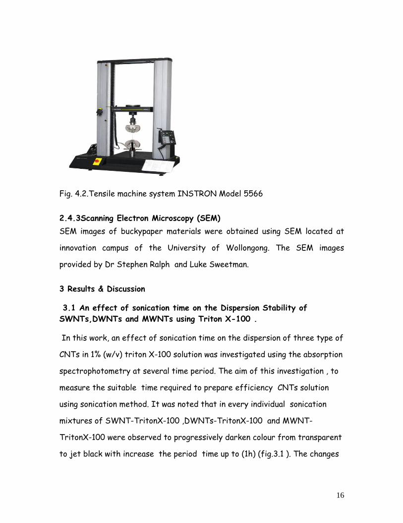
2.4.2 mechanical properties
The mechanical properties of buckypaper membranes were tested using an
Instron 5566 tensile tester (fig4.2). Buckypaper samples measuring at
different width x 10mm length were clamped between two parallel plates. A
constant extension rate of 0.1 mm/min was then applied to the system until
sample failure with the required mechanical stress and strain being
recorded at the same time. This testing was used to determine the Young’s
modulus, strength and ductility of the buckypaper samples.
16
Fig. 4.2.Tensile machine system INSTRON Model 5566
2.4.3Scanning Electron Microscopy (SEM)
SEM images of buckypaper materials were obtained using SEM located at
innovation campus of the University of Wollongong. The SEM images
provided by Dr Stephen Ralph and Luke Sweetman.
3 Results & Discussion
3.1 An effect of sonication time on the Dispersion Stability of
SWNTs,DWNTs and MWNTs using Triton X-100 .
In this work, an effect of sonication time on the dispersion of three type of
CNTs in 1% (w/v) triton X-100 solution was investigated using the absorption
spectrophotometry at several time period. The aim of this investigation , to
measure the suitable time required to prepare efficiency CNTs solution
using sonication method. It was noted that in every individual sonication
mixtures of SWNT-TritonX-100 ,DWNTs-TritonX-100 and MWNT-
TritonX-100 were observed to progressively darken colour from transparent
to jet black with increase the period time up to (1h) (fig.3.1 ). The changes

17
in the mixtures colour resulting from the aggregates of CNTs at the base of
the solution were reduced during the sonication procedure.
Fig 3.1: The changes in the mixtures colour during ultrasonication4.
Fig. 3.2,3.3&3.4, have shown the effect of increasing sonication time on the
absorption spectrum of a samples containing SWNT-TritonX-100 ,DWNTs-TritonX-100
and MWNT-TritonX-100 . It can be said that the observed absorption bands were
resulting from separation of practicals of SWNTs,DWNTs and MWNTs in the
solutions. An increase of the sonication time led to in both greater overall
absorbance, and the bands indicated that van Hove singularity becoming
noticeable1.
The inserted Fig.1,2&3 have shown the effect of sonication time on the absoption
at 600nm. All three figures have shown clearly that the absorbance was increasing
rapidly at the first fifteen minutes and then slightly arising until around thirty
minutes . The differences between the absorbance values between 30 and 60
minutes were not significantly effective on the sonication time. For this reason, it
was determined 30 minutes as favourite sonication time for synthesis bukypaper
from MWNTs, DWNTs and SWNTs which agreed with other researchers1 .
transparent Jet black

18
Fig. 3.2 Effect of increasing sonication time on the UV-visible absorption
spectrum of a dispersion containing 0.1% (w/v) SWNT and 1% (w/v) Triton
X-100. The inset shows how the absorbance at 600 nm varied in response to
changes in sonication time. All samples were measured after being diluted
20times using Milli-Q water.
Fig. 3.3 Effect of increasing sonication time on the UV-visible absorption
spectrum of a dispersion containing 0.1% (w/v) DWNT and 1% (w/v) Triton
X-100. The inset shows how the absorbance at 600 nm varied in response to
changes in sonication time. All samples were measured after being diluted
20times using Milli-Q water.

19
Fig. 3.4 Effect of increasing sonication time on the UV-visible absorption
spectrum of a dispersion containing 0.1% (w/v) MWNT and 1% (w/v) Triton
X-100. The inset shows how the absorbance at 600 nm varied in response to
changes in sonication time. All samples were measured after being diluted
20times using Milli-Q water.
Microscopy Testing
Images.3.1,3.2&3.3 have shown the optical microscopy of the SWNT–Triton
X-100, DWNT–Triton X-100 and MWNT–Triton X-100 dispersions obtained
after 60 min sonication time . Three images have indicated clearly there
were no significant aggregates present in these solutions.
Image3.1.MWNT-Triton X-100 dispersion Image3.2.DWNT-Triton X-100 dispersion
Image3.3.SWNT-Triton X-100 dispersion

20
3.2 Absorbance Analysis
Comparisons of an effect of (1%)Triton X-100 on production SWNT ,
DWNTs and MWNT despersions were done by comparing the absorbances of
dispersions containing equivalent loadings of (0.15gm)Triton X-100 in 15ml
Milli-Q water & 1% from each CNTs at 30 minuets dispersions time
(Fig.3.5). The MWNTe was found to be the high readily able to dispersion in
Triton X-100. The DWNT and SWNT were nearly the same in their ability in
dispersing in Triton X-100.
Figure3.5 : Effect of Triton X-100 on the production of SWNT,DWNT &
MWNT dispersions.
3.3 Conductivity analysis:
The conductivity of SWNTs,DWNTs& MWNTs buckypaper samples was
measured by comparing the resistance of buckypaper samples of varying
lengths. A linear relationship between current and voltage in the application
of Ohm’s Law. All bukypaper samples showed current/voltage data with good
agreement to their respective linear squares regressions R2 .(Fig.3.6).

21
Figure3.6 : Current-Voltage characteristics for a buckypaper prepared from
SWNTs, DWNTs & MWNTs in triton-100 dispersions.
As reported by Boge et al1., the total resistance (Rt) can be :
Rt = L (Aσ) -1 + Rc,
where L is the length of the buckypaper(in cm), A is its cross sectional area
(in cm2), σ is the bulk conductivity and Rc is the contact resistance ((in Ω).).
As the contact resistance is constant for all sample lengths a plot of total
resistance vs. sample length will give a slope of A-1σ -1.
The conductivity (σ), in (in S cm-1), is then given by
σ = 1/(m *A)
SWNT DWNT
MWNT

22
where m is the slope of a plot of resistance vs.sample length (fig.3.7)
Table 3.1 : Conductivities of the three buckypaper samples produced from
SWNTs, DWNTs & MWNTs dispersed in tritonX-100.
Bucky paper SWNTs DWNTs MWNTs
Conductivity (Scm-1) 14.24
22.98
18.9
The table3.1 has shown that the DWNT has the highest conductivity
following by MWNT. The SWNT was 38% less conductivity than DWNT.
Fig3.7: The correlation between electrical resistance and changing the
length of a strip of buckypaper prepared from SWNT-TritonX-100
,DWNTs-TritonX-100 and MWNT-TritonX-100.

23
3.5 Mechanical Analysis
The most important characteristics of buckypaper is the mechanical
properties dut to their roles in determining their applications1.
Stress-strain relationships were evaluated for each of the three buckypaper
samples to determine their mechanical properties (Fig.3.8 ). MWNT , DWNT
and SWNT Buckypapers were observed to undergo elastic deformation
during the initial stretching, producing a linear stress-strain region from
which the Young’s Modulus (E) was calculated using,
E = σ ε-1,
where, σ is the tensile stress applied to the material, and ε is the tensile
strain of the material.
Table 2. Strength , strain at highest point and YOUNG'S MODULUS for
bukypapers prepared from SWNT-TritonX-100 ,DWNTs-TritonX-100 and
MWNT-TritonX-100.
TENSILE
STRENGTH
Mpa
%STRAIN
YOUNG'S
MODULUS
MWNT 2.55±0.27 2.84±0.57 224.12±22
DWNT 0.77 0.43 31.67
SWNT 2.21±0.44 2.08±0.58 209±49
MWNT
SWNT
DWNT

24
Fig .3.8 Stress-strain curves for bukypapers made from buckypapers
prepared from SWNT-TritonX-100 ,DWNTs-TritonX-100 and MWNT-
TritonX-100.
The stretching was observed to give inelastic nature of the buckypaper, and
extensions generated in this region being unrecoverable after the release of
stress. Finally, after sufficient extension, failure of the buckypapers were
determined. The materials tensile strength and strain were determined from
this point as in table .3.2 .
Table3.2 & fig3.8 have shown significant variations in mechanical properties
were observed between DWNT bukypaper and the other two CNTs. The
Table .3.2 clearly indicated that There was no big differences in Tesile
strength , strain and Young’s modules of bukypapers prepared from SWNT-
TritonX-100 and MWNT-TritonX-100 suggesting both them have slightly
same mechanical properties. On other hand , there was great differences
between them and bukypaper prepared from DWNTs-TritonX-100 . The
Table has illustrated that the Tesile strength , strain of bukypaper prepared
from MWNT were greater by 70% and 85% respectively than bukypaper
prepared from DWNTs. From above , it can be said that DWNT bukypaper
has poor mechanical properties in contrast to MWNTs & SWNTs.
3.6SEM images:
Fig 3.9 have shown that there were a significants in the surfaces of buky
papers prepared from SWNT-TritonX-100 ,DWNTs-TritonX-100 and MWNT-
TritonX-100. Fig S2,D1 & M2 have indicated clearly that there were some
regions that appeared to containing some aggregates of SWNT , DWNT and
MWNT. The Images 20,000X have indicated that the DWNT bukypaper has
significant large bundling of CNTs ( imag.D1) in contrast with the same

25
magnification of SME images of SNWT & MWNT (imag.S1&M3) . In addition
, the Image.M3 has shown there was few bundling of MWNT but larger than
the bundling of SWNT ( image.S1). Image.S1 has shown a lot of very small
aggregates of SWNT.
a hundred thousand times magnification SEM images resolved nanotube
ropes corresponding to the bundling of only a few SWNTs (image.S1) , one
large bundling of DWNTs (image.D3) and two bundling of
MWNT(image.M2).imageM3 has shown clearly there was no bundling of
CNTs which provide signs of high quality of the sonication procedure. the
bundling of CNTs in our bukypapers might be minimized by increasing
sonication time . The CNTs rope lengths were visualised indicating that the
rope lengths is longer in MWNT than DWNT and SWNT.

26
SEM imaging - 1/SWNT
2/DWNT
S1 S2
S3
D1 D2
DWNT
aggregates
SWNT
aggregates
SWNT raps

27
3/ MWNT
Figure 3.9: SEM images of a CNT buckypaper produced from SWNT-
TritonX-100 ,DWNTs-TritonX-100 and MWNT-TritonX-100.
M1
D3
M2
M3
MWNT
aggregates
28
4:Conclusions :
In this project bukypaper of MWNTs, DWNTs and SWNT were successfully
disperse using Triton X-100 as a solvent . The suitable dispersions time of
all these CNTs was around 30minuts which confirmed by UV-Vis absorbance
measurements at several amount of times .The Young’s modulus ,tensile
strengths and strain were extremely high in MWNTs and SWNTs
bukypapers than DWNTs . DWNTs bukypaper was very brittle and it was
easy to break making some difficulties to measure its mechanical
properties. The SEM images confirmed that the DWNT has big bundling
which might be the reason for its poor mechanical properties This can be
avoided by increasing the dispersions time in further works. SEM images of
the buckypaper of MWNT were highly homogeneous with very small amount
of aggregation, containing long ropes . Conductivities of the three
buckypaper samples produced from SWNTs, DWNTs & MWNTs dispersed in
tritonX-100 were low in SWNTs in contrast to MWNTs & DWNTs.
4.Acknowledgements
First of all I would like to thank Allah for his blessing and guidance without
which I couldn’t finish this report . I would like also to thank the University
of Wollongong, School of Chemistry for computational facilities , Academic
resources and on chemical materials & instruments facilities. I would also
like to thank Dr Stephen Ralph, subject coordinator (CHEM991) for his
guidance , support and motivation which was useful for doing this report .I
would also like thank Luke Sweetman (PhD Candidate) for helpful
discussions ,training on synthesis Bucky paper , using techniques in
determining of physical ,electrical and mechanicals properties and continuous
guidance, support and academics resources .Lastly but in no way the least I
would like to thank my family and friends for their continuous support
,prayers and love .

29
4. References
1Boge ,J et al ,2009The effect of preparation conditions and biopolymer dispersants on the
properties of SWNT buckypapers
2Dresselhaus,M.S & Dresselhaus ,G ,Avouris ,P ,2000. Carbon Nanotubes
Synthesis,structure,properties, and applications.New York
3 Sherrell P. (2007) ‘Novel Nanocomposite Electrodes for Energy Applications’ School of
Chemistry, Honours thesis, University of Wollongong
4Peng Cheng Ma a,1, Jang-Kyo Kim a,*, Ben Zhong Tang b,2 Functionalization of carbon
nanotubes using a silane coupling agent
5http://eng.ofssvs1.ru/download/pribor/img698.jpg 6 Marc in het Panhuis , Chem 301/991: Advanced Materials & Nanotechnology lectuers nots,
https://vista.uow.edu.au/webct/urw/lc20663.tp0/cobaltMainFrame.dowebct
7 Endo.M,Strano.M.S & Ajayan.P.M 2008. Potential Applications of Carbon
Nanotubes.Appl.Physics 111,13-62.
8 Smajda,S ,Kukovecz.A Konya.Z & Kiricsi.I 2007. Structure and gas permeability of multi-
wall carbon nanotube bukypapers. Sciencedirct,1176-1184
9 Kim,A,Y . Muramatsu.H. Hayashi.T. Endo.M.Terrones.M &Dresselhaus.M.S .2005.
Fabrication of high-purity,Double-wall carbón Nanotube Bukypaper. Chemical vapor
Deposition.12,237-330


