Download - Synchronous Machine - elektro.fs.cvut.cz
Synchronousmachine
1. Construction
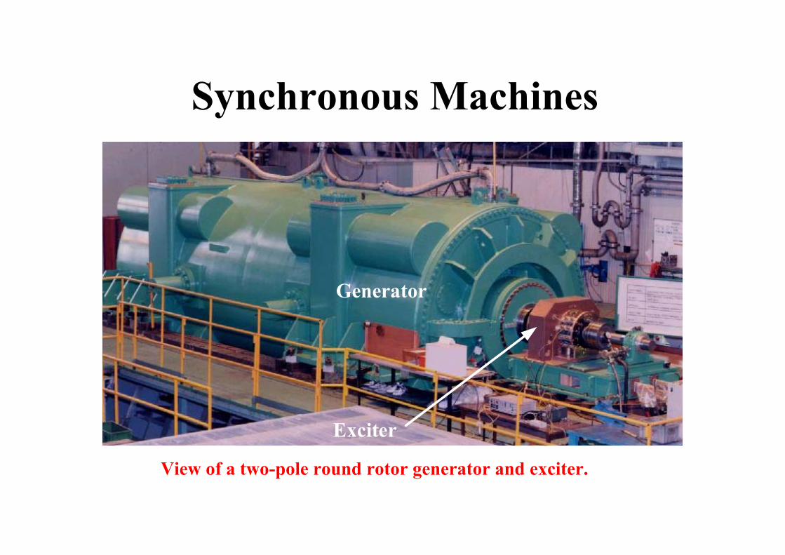
Synchronous Machines
Generator
Exciter
View of a two-pole round rotor generator and exciter.

Synchronous Machines
Major components of a round rotor two-pole generator
N S
A-
B+
C-
A
C
BStator with
laminated iron core
Slots with phase
winding
Rotor with dc winding
A+
B-
C+
+
+ +
++
-
- -
--
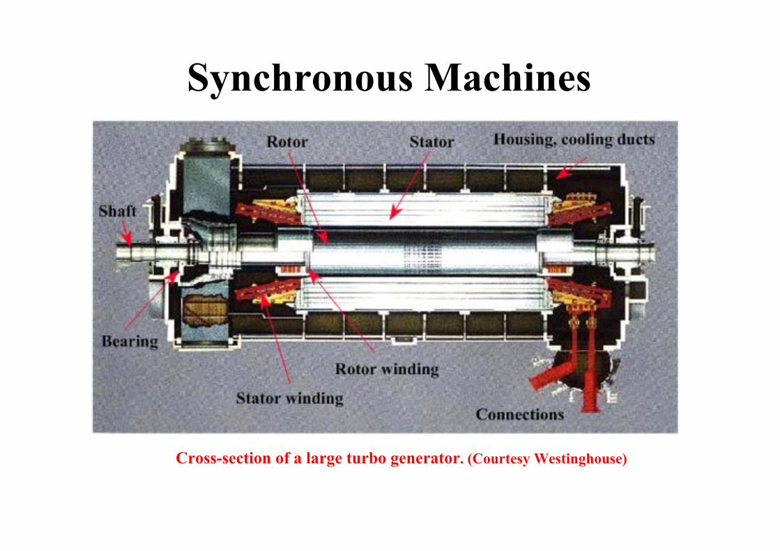
Synchronous Machines
Cross-section of a large turbo generator. (Courtesy Westinghouse)

Synchronous Machines
Details of a generator stator.
Laminated iron core with slots
Insulated copper bars are placed in the slots to form the three-phase winding
Metal frame
Synchronous Machines
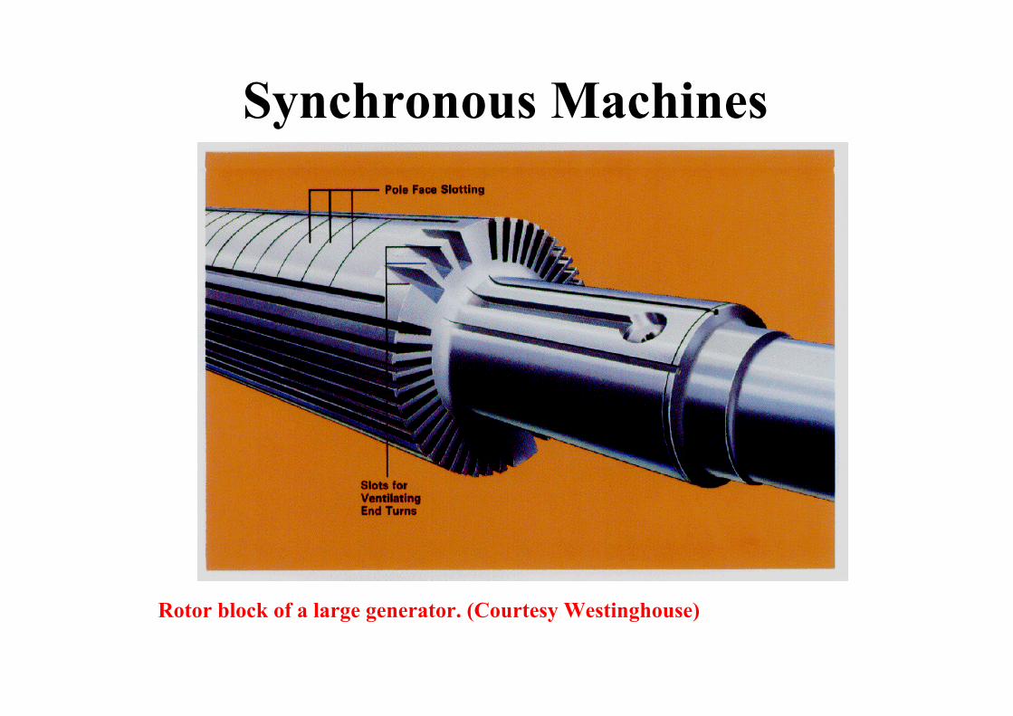
Rotor block of a large generator. (Courtesy Westinghouse)
Synchronous Machines
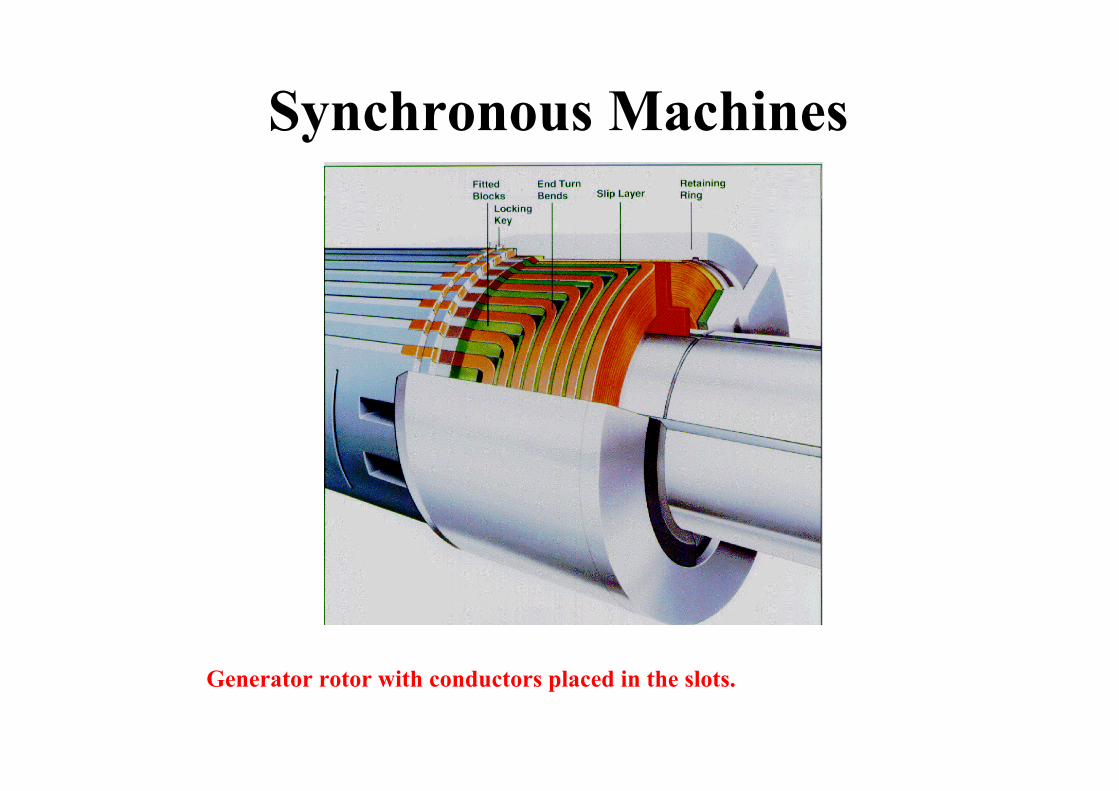
Generator rotor with conductors placed in the slots.

Synchronous Machines
Large generator rotor completely assembled. (Courtesy Westinghouse)
DC current terminals
Shaft
Steelretaining
ring
DC currentterminals
Wedges
Shaft

Synchronous Machines
Two-pole salient pole generator concept.
B-
B+
A+
C+
C-
A-
Rotor with dc winding
Stator with laminated iron core
N
SSlots with
phase winding
+++++
-----
Synchronous Machines
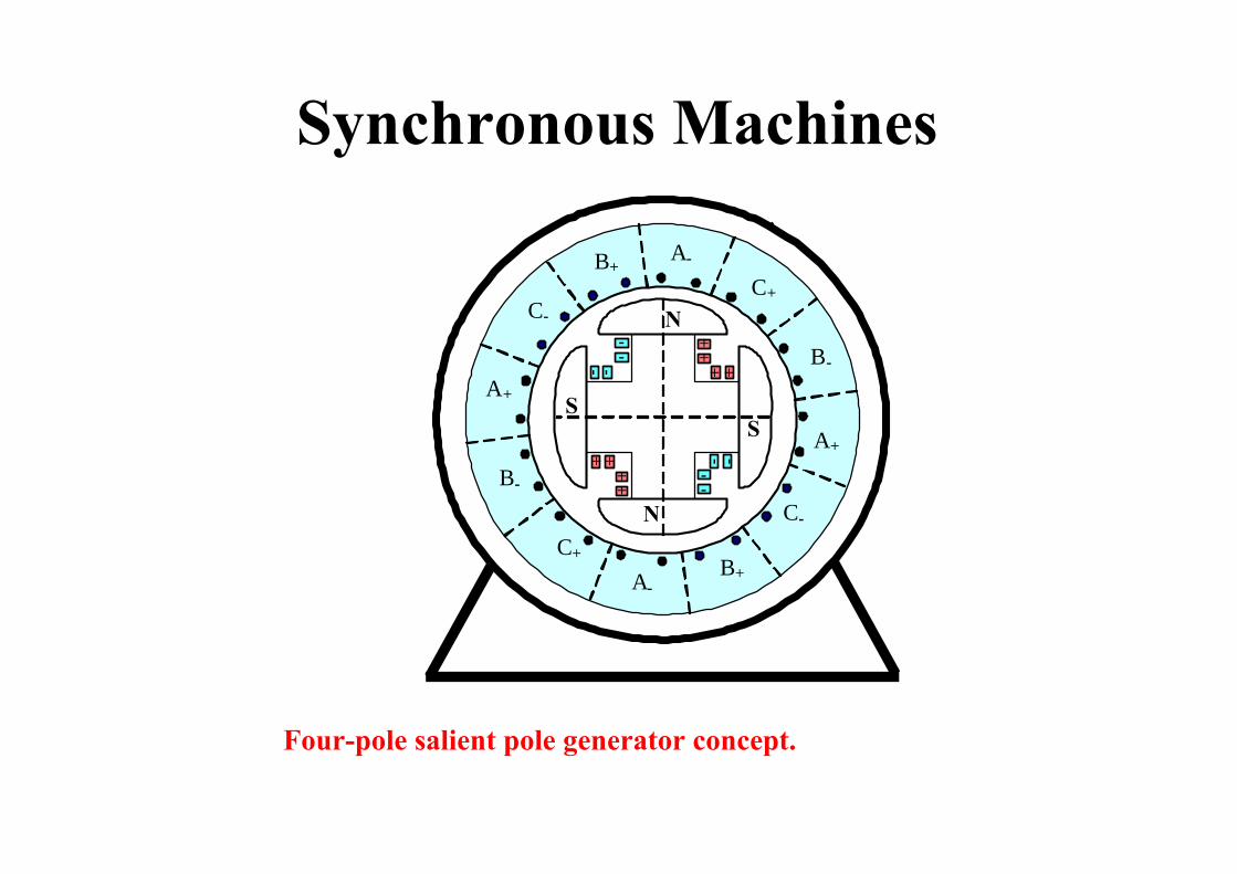
Four-pole salient pole generator concept.
B-
B+
A+
C+C-
A-
-- +
+
--+ +--
+ +
--+
+
N
SS
N
A+
C-
B+A-
B-
C+
Synchronous Machines
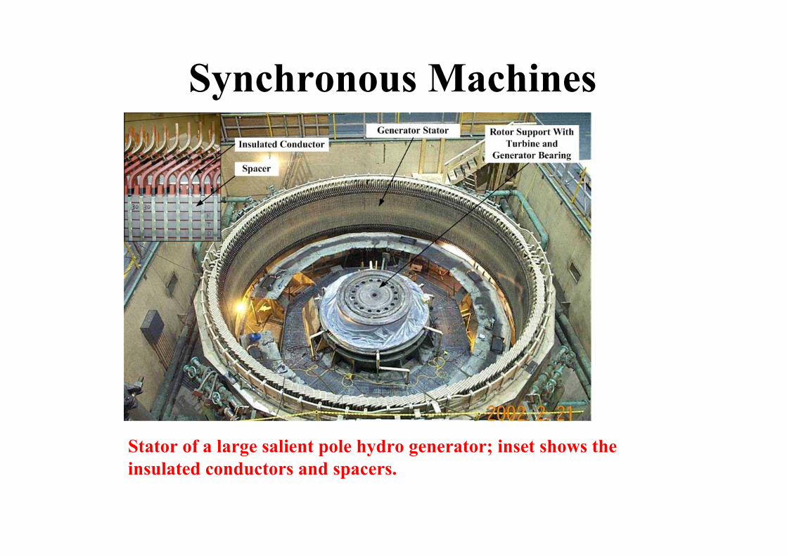
Stator of a large salient pole hydro generator; inset shows the insulated conductors and spacers.
Synchronous Machines
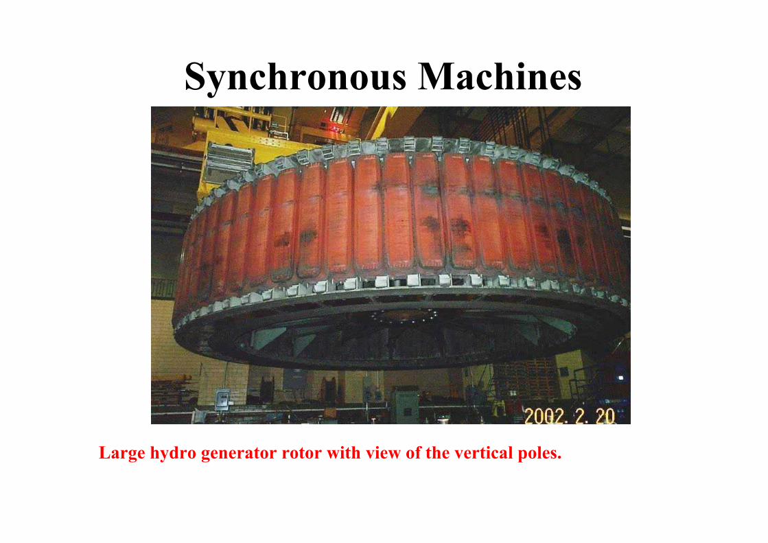
Large hydro generator rotor with view of the vertical poles.

Synchronous Machines
Rotor of a four-pole salient pole generator.
Pole
DC excitationwinding
Fan
Sliprings
Synchronous Machines
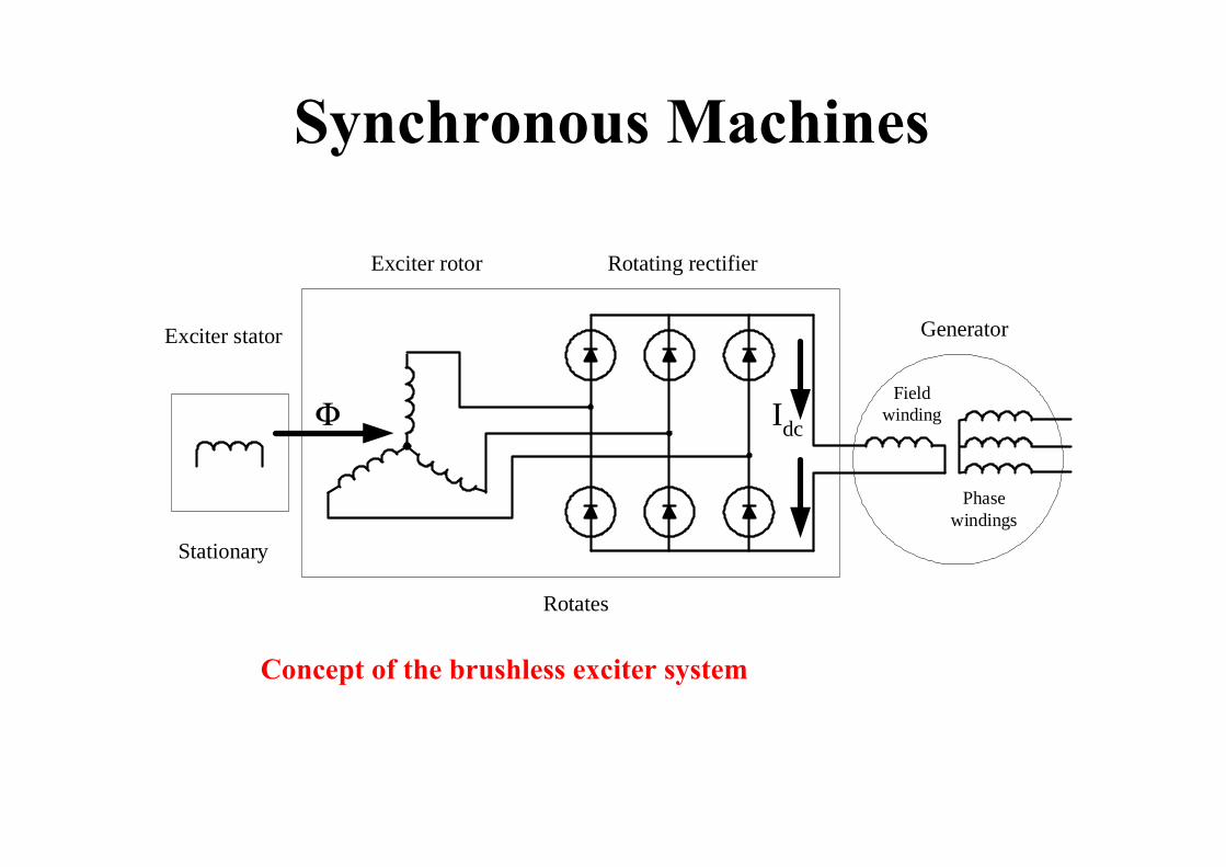
Concept of the brushless exciter system
Generator
Rotating rectifierExciter rotor
Exciter stator
Fieldwinding
Phasewindings
Rotates
Stationary
Φ Idc

Operating Concept

Synchronous Machines
Operating concept of a synchronous generator
A+
Flux Φfnsy
A-
C+
B+C-
B-
N
S
-
++
++-
--
-
+

Synchronous Machines
Rotation produced flux linkage variation.
N
S
-
+
+
-
+N
S
No flux linkage with phase AMaximum flux linkage with phase A
B+
A+
C+
A-
C-
B- B-
A+
C- B+
A-
C+
- + -
+
-
+
- +
-
+-
(a) Flux is perpendicular to phase A (b) Flux is parallel to phase A

Synchronous Machines
Rotating flux linkage to phase A.
30
nsy
A+ A-
C+
B+C-
B-
N
S
-
++
++-
--
-
+
ΦlinkΦrotωt

Synchronous MachinesMain rotating flux
synπω 2=
)cos()( tt rotlink ωΦ=Φ
dttdNtE link
stas)()( Φ=
)90cos()sin()(
°+Φ=Φ−=
tNtNtE
rotsta
rotstas
ωωωω
2ωrotsta
staNE Φ
=
2pfnsy =
The rotating flux generates the induced voltage

Synchronous Machines
30
nsy
A+
A-
C+
B+C-
B-
N
S
-
++
++-
--
-
+Field flux ΦfArmatureflux Φar
Field (Φf) and load generated (Φar) rotating fluxes.
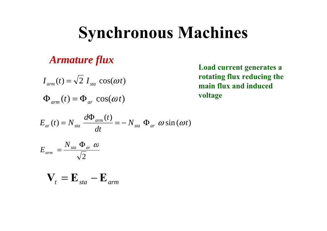
Synchronous MachinesArmature flux
)cos(2)( tItI staarm ω=Load current generates a rotating flux reducing the main flux and induced voltage)cos()( tt ararm ωΦ=Φ
)(sin)(
)( tNdt
tdNtE arstaarm
staar ωωΦ−=Φ
=
2ωarsta
armNE Φ
=
armstat EEV −=
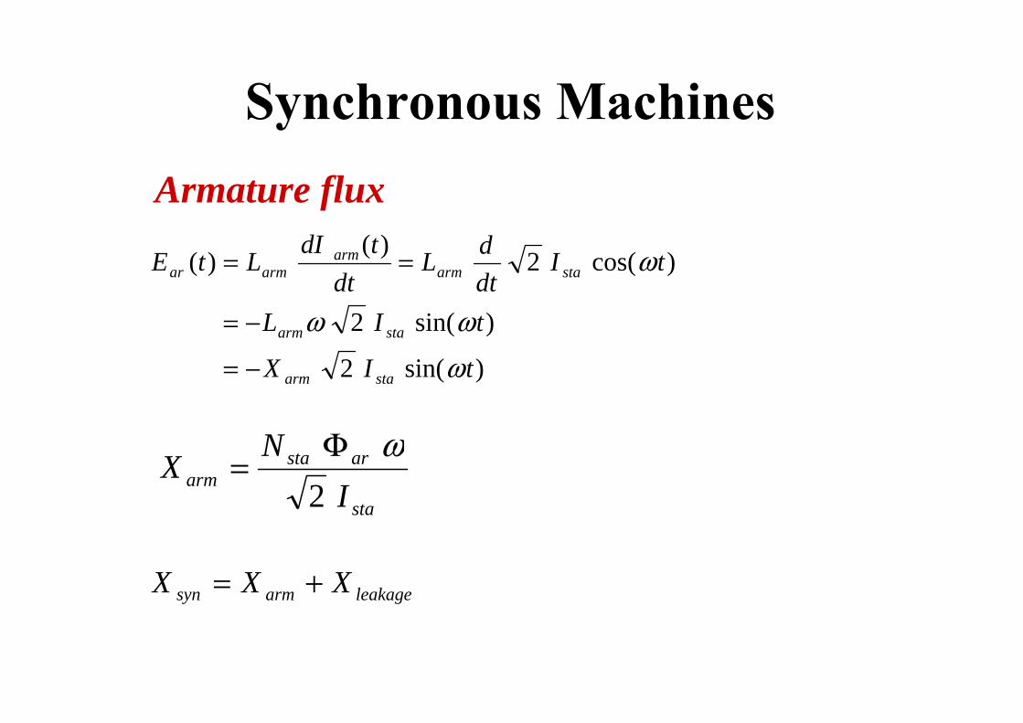
Synchronous MachinesArmature flux
)sin(2
)sin(2
)cos(2)()(
tIX
tIL
tIdtdL
dttdILtE
staarm
staarm
staarmarm
armar
ω
ωω
ω
−=
−=
==
sta
arstaarm I
NX2
ωΦ=
leakagearmsyn XXX +=

Synchronous MachinesSingle phase equivalent circuit )( synstasynarm XjIE =−
synstastasynarmstat XjIEEEV −=−= −
DC
VtEstaIsta
Xsyn Rsta
Flux
Single-phase equivalent circuit of a synchronous generator.

Synchronous Machines• The generator is loaded• The load current produces a rotating flux• This rotating flux induces a ac three phase voltage in
the stator winding.• This voltage is
– subtracted from the induced voltage.– represented by a voltage drop on the synchronous reactance
• The equivalent circuit of a synchronous generator is a voltage source and a reactance connected in series
Synchronous Machines
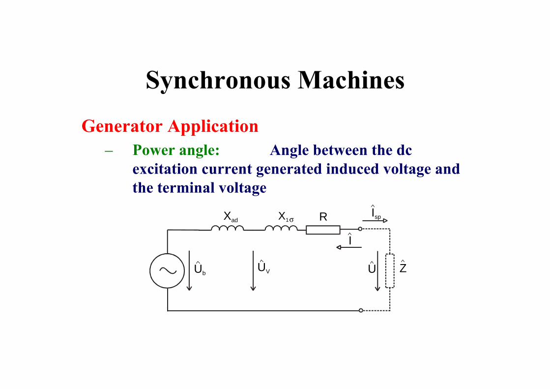
Generator Application– Power angle: Angle between the dc
excitation current generated induced voltage and the terminal voltage
UbUV ZU
XadIsp
I
RX1σ

Synchronous Machines• Phasor diagram of synchronous
machine
I R + I Xj + I Xj +UU 1adbˆˆˆˆˆ
σ= I R + I Xj + I Xj +UU 1adbˆˆˆˆˆ
σ=
I R + I Xj + I Xj +UU 1adbˆˆˆˆˆ
σ=

Synchronous MachinesGenerator Application
– Loading: power is less than angle 90 deg• All generators in the system are connected in parallel• All generators rotates with the synchronous speed• The load can be increased by increasing the input mechanical power by
regulating the turbine impute power• The speed does not change, the power angle increases• Maximum power angle is 90 degree, beyond that operation is unstable
– Reactive power regulation– When the excitation is:
• Increased, the generator reactive power also increases;• Decreased, the generator reactive power also decreases

• Load and excitation dependence
I (Isp)
Un
0kap
0,2kap0,6kap
0,8ind0ind
1
U
I
0kap
0,6kap
0,6ind
0ind
1
I b

Synchronous Machines
Synchronization– Verify that the phase sequences of the two systems are the
same.
– Adjust the machine speed with the turbine that drives the generator until the generator voltage frequency is nearly the same as the frequency of the network voltage.
– Adjust the terminal voltage of the generator by changing the dc field (rotor) current until the generator terminal voltage is almost equal to the network voltage. Acceptable limit is 5%.
– Adjust the phase angle of the generator terminal voltage by regulating the input power until it is nearly equal with the phase angle of the network voltage. Acceptable limits are about 15°.

Synchronous Machines
• Synchronization
A
L1
L2
L3
NAPÁJENÍBUZENÍ
V2 f2
V1 f1
SA

The generator and network power vs power angleδ 0deg 1deg, 180deg..:=
0 30 60 90 120 150 1800
50
100
150
200
250
Pg δ( )kW
Pnet δ( )kW
110
δdeg
Stable operation
Unstable operationMaximum
power
Operation point


