Download - Surveying II Manual 21.11.13
8/12/2019 Surveying II Manual 21.11.13
http://slidepdf.com/reader/full/surveying-ii-manual-211113 1/61
1
SHREE VENKATESHWARA HI – TECH
ENGINEERING COLLEGE
GOBI – 638 455
DEPARTMENT OF CIVIL ENGINEERING
MANUAL
CE 2259 – SURVEYING PRACTICAL II
ANNA UNIVERSITY CHENNAI – 600 025
(Regulation 2008)
II – Year IV – Semester
Prepared by
Mr.J.Saravanakumar, ME
Assistant professor / Civil
Staff HOD Principal

8/12/2019 Surveying II Manual 21.11.13
http://slidepdf.com/reader/full/surveying-ii-manual-211113 2/61
2
8/12/2019 Surveying II Manual 21.11.13
http://slidepdf.com/reader/full/surveying-ii-manual-211113 3/61
3
TABLE OF CONTENTS
S.No. Name of the experimentPage
No.Marks Remark
1. Study of theodolite 2
2.Measurement of horizontal angles by reiteration
method10
3. Measurement of horizontal angle by repetition method 14
4. Measurement of vertical angles 18
5. Closed theodolite traverse - Measuring included angle 19
6. Heights and distances by single plane method 23
7. Heights and distances by Double plane method 25
8. Tangential system 27
9. Stadia system 33
10.Determination Of The Multiplying And Additive
Constant37
11. Setting out work- Foundation marking 42
12. Setting out of a simple curves by long chord method 44
13. Setting out of a curves by Rankine’s method 47
14.Determination of Azimuth of Survey line by
observation of sun50
15. Field work using Total Station 51
16. Measurements Of Distance And Co-Ordinates Of GivenPoints
54
17. Subtense bar method 57
Average of marks

8/12/2019 Surveying II Manual 21.11.13
http://slidepdf.com/reader/full/surveying-ii-manual-211113 4/61
4
8/12/2019 Surveying II Manual 21.11.13
http://slidepdf.com/reader/full/surveying-ii-manual-211113 5/61
5
EX.NO:1
DATE:
STUDY OF THEODOLITE
AIM:
To study the component parts, temporary adjustment of a theodolite and reading
horizontal angle.
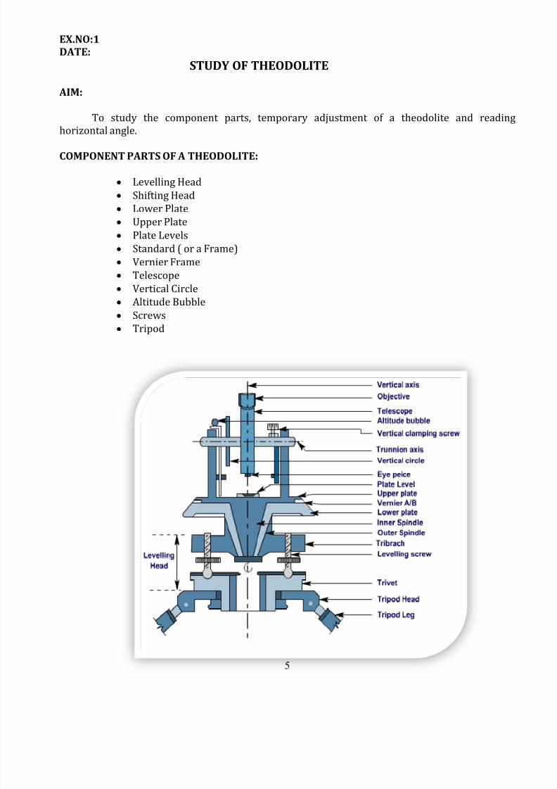
COMPONENT PARTS OF A THEODOLITE:
Levelling Head
Shifting Head
Lower Plate
Upper Plate
Plate Levels
Standard ( or a Frame)
Vernier Frame
Telescope Vertical Circle
Altitude Bubble
Screws
Tripod
8/12/2019 Surveying II Manual 21.11.13
http://slidepdf.com/reader/full/surveying-ii-manual-211113 6/61
6
1. Levelling Head:
It is the lowermost part of a theodolite. It consists of two parallel horizontal plates
separated by three levelling screws.
The lower plate with a large threaded hole in its centre is called trivet or foot plate. It
provides a means to place the instrument on (tripod) stand and get it screwed. Its central
aperture provides a way for suspending a plumb bob.
The upper plate of the leveling head is called the tribrach . It contains a tapered bearing
at the centre. It has three arms each carrying a leveling screw. It provides a support for theupper part of the instrument.
The principal use of levelling head is to provide a means for levelling the instrument.
2. Shifting Head:
It consists of a pair of horizontal plates and an annular treaded ring. One of the plates is
placed below the lower plate but above the tribrach and the other below the tribrach. The
annular treaded ring is placed in between lower plate and the tribrach which is used to
tighten/untighten the whole of the instrument. The shifting head is used for exact centring of
the instrument after leveling has been completed.
3. Lower Plate:
It is a horizontal circular plate monolithically constructed with the outer spindle. A
scale is engraved at its beveled edge with divisions in degrees and minutes increasing in
clockwise direction. It provides the main scale reading of a horizontal angle and a means to
fix / unfix the whole of the instrument.
4. Upper Plate:
It is a horizontal circular plate monolithically constructed with the inner spindle. It
is fitted with two diametrically opposite vernier scales designated as A and B. Functions of
upper plates are to support a pair of magnifiers for the verniers, a pair of plate levels, a pair
of support frames for telescope and a means to fix / unfix the upper plate of the instrument
with its lower plate.
5. Plate Levels:
A pair of level tubes is placed at right angles on the upper plate. These are used to
make the vertical axis of the instrument truly vertical i.e., for leveling of the instrument.
6. Standard ( or a Frame):
Two standards resembling the letter a are attached on the upper plate. These
provide the bearings of the pivots of the telescope allowing it to rotate on its trunnion axis
in vertical plane. The vernier frame and arm of vertical circle clamp are also attached to it.
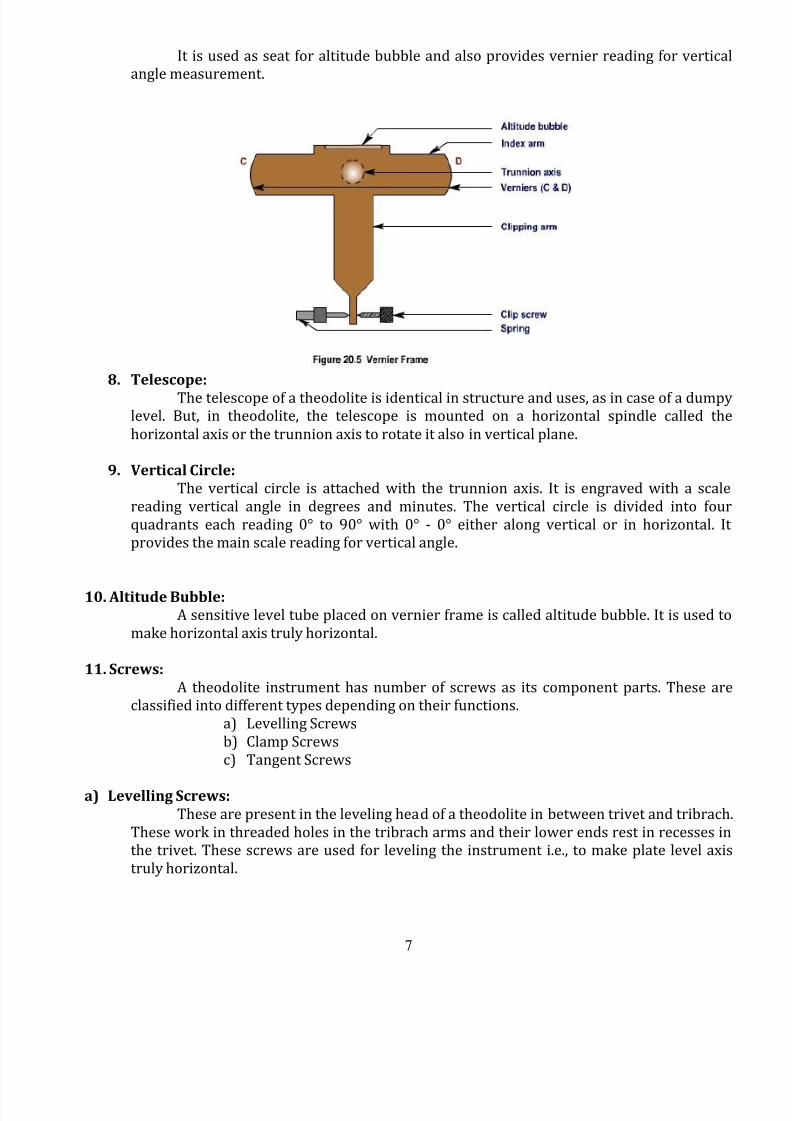
7. Vernier Frame:
Also called T -frame or index frame, consists of a vertical leg known as clipping arm
and a horizontal bar called the index arm engraved with verniers C and D at its ends. Each
of the verniers at C and D are having two scales which increase in opposite
directions.
8/12/2019 Surveying II Manual 21.11.13
http://slidepdf.com/reader/full/surveying-ii-manual-211113 7/61
7
It is used as seat for altitude bubble and also provides vernier reading for vertical
angle measurement.
8. Telescope:
The telescope of a theodolite is identical in structure and uses, as in case of a dumpylevel. But, in theodolite, the telescope is mounted on a horizontal spindle called the
horizontal axis or the trunnion axis to rotate it also in vertical plane.
9. Vertical Circle:
The vertical circle is attached with the trunnion axis. It is engraved with a scale
reading vertical angle in degrees and minutes. The vertical circle is divided into four
quadrants each reading 0° to 90° with 0° - 0° either along vertical or in horizontal. It
provides the main scale reading for vertical angle.
10. Altitude Bubble:
A sensitive level tube placed on vernier frame is called altitude bubble. It is used to
make horizontal axis truly horizontal.
11. Screws:
A theodolite instrument has number of screws as its component parts. These are
classified into different types depending on their functions.
a) Levelling Screws
b) Clamp Screws
c) Tangent Screws
a) Levelling Screws:
These are present in the leveling head of a theodolite in between trivet and tribrach.
These work in threaded holes in the tribrach arms and their lower ends rest in recesses in
the trivet. These screws are used for leveling the instrument i.e., to make plate level axis
truly horizontal.
8/12/2019 Surveying II Manual 21.11.13
http://slidepdf.com/reader/full/surveying-ii-manual-211113 8/61
8
b) Clamp Screws:
These are used to fix the parts of a theodolite with which these are attached.
i. Lowerplate Clamp Screw
ii. Upperplate Clamp Screw
iii. Vertical plate Clamp Screw
i. Lowerplate Clamp Screw:
The clamp screw attached to the lower plate of a theodolite is called lower plate
clamp screw. When it is tightened, the outer spindle gets fixed with the tribrach, and, thus,the lower plate gets fixed in position.
ii. Upperplate Clamp Screw:
The clamp screw attached with the upper plate of a theodolite is called upper plate
clamp screw. When it is tightened, the inner spindle gets fixed with the outer spindle and,
thus, the upper plate gets fixed in position.
The manipulation of the upper plate and lower plate clamp screws provide three
conditions:
When both the upper plate clamp screw and the lower plate clamp screw are
tightened, the instrument gets fully fixed.
When the upper plate clamp screw is tightened and the lower plate clamp
screw is opened, the instrument rotates on its outeraxis, There is no relative
motion between the two plate and the readings in the horizontal vernier
scales do not change.
When the lower plate clamp screw is tightened, and the upper plate is
opened, the instrument rotates on the inner axis with outer axis fixed. The
readings in the horizontal vernier scales change.
iii. Vertical plate Clamp Screw:
It is present on a frame fixed with standard and above the shaft of trunnion axis. It is
used to clamp the telescope in any plane and hence at any desired vertical angle.
c) Tangent Screws:
With each clamping screw, there is a tangent screw present in the instrument to
provide fine movement. The tangent screws work only after its clamping screws get
tightened. Thus when the upper clamp screw has been tightened, small movement of the
upper plate can be made by the upper tangent screw; when the lower clamp screw has
been tightened, small movement of the lower plate can be made by the lower tangent screw
and similarly for vertical clamp screw.
12. Tripod:
The theodolite is mounted on a strong tripod when being used in the field. The legs of thetripod are solid or framed. At the lower ends of the legs, pointed steel shoes are provided to get
them pushed into ground. The tripod head has male screws on which the trivet of the leveling
head is screwed.
8/12/2019 Surveying II Manual 21.11.13
http://slidepdf.com/reader/full/surveying-ii-manual-211113 9/61
9
Adjustments of aTransit Theodolite:
The adjustments are mainly of two types. There are,
1) Permanent adjustments
2) Temporary adjustments
1) Permanent adjustments:
Adjustments made to establish fixed relations between the fundamental lines of a
theodolite are known as permanent adjustments. These adjustments once made remainpermanent for a long period.
2) Temporary adjustments:
Adjustments made at each setting of the instrument before taking observations are known
as temporary adjustments.Temporary Adjustments includes,
a) Setting up the level
b) Levelling up
c) Elimination of parallax
a) Setting up the level :
This operation includes fixing the instrument on the tripod and also approximate levelling
by leg adjustment.
b) Levelling up :
Accurate levelling is done with the help of foot screws and by using plate levels. The object
of levelling up the instrument is to make its vertical axis truly vertical.
c) Elimination of parallax:
If the image formed by the objective does not lie in the plane of the cross hairs, there will be
a shift in the image due to shift of the eye. Such displacement of image is termed as parallax.
Parallax is removed in two stages.
Focusing the eye for distinct vision of cross hairs.
Focusing the objective so that image is formed in the plane of cross hairs.
Reading the horizontal angles:
A horizontal angle is the angular measurement between two points. The angles are
measured in the horizontal plane. It can be expressed in this way also. A horizontal angle is the
angle formed by two intersecting vertical planes at their point of intersection.
The following is the procedure to read the vernier,
1) The main scale reading is taken to the zero of the vernier . ( Refer fig. in A-Vernier)
8/12/2019 Surveying II Manual 21.11.13
http://slidepdf.com/reader/full/surveying-ii-manual-211113 10/61
10
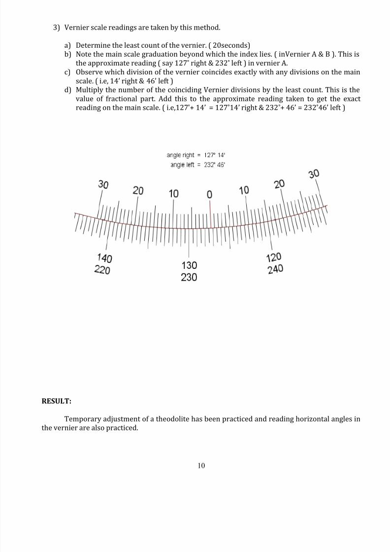
3) Vernier scale readings are taken by this method.
a) Determine the least count of the vernier. ( 20seconds)
b) Note the main scale graduation beyond which the index lies. ( inVernier A & B ). This is
the approximate reading ( say 127° right & 232° left ) in vernier A.
c) Observe which division of the vernier coincides exactly with any divisions on the main
scale. ( i.e, 14’ right & 46’ left )
d) Multiply the number of the coinciding Vernier divisions by the least count. This is the
value of fractional part. Add this to the approximate reading taken to get the exactreading on the main scale. ( i.e,127°+ 14’ = 127°14’ right & 232°+ 46’ = 232°46’ left )
RESULT:
Temporary adjustment of a theodolite has been practiced and reading horizontal angles in
the vernier are also practiced.
8/12/2019 Surveying II Manual 21.11.13
http://slidepdf.com/reader/full/surveying-ii-manual-211113 11/61
11
B
A
O
D
C
8/12/2019 Surveying II Manual 21.11.13
http://slidepdf.com/reader/full/surveying-ii-manual-211113 12/61
12
Ex.No.2 DATE:
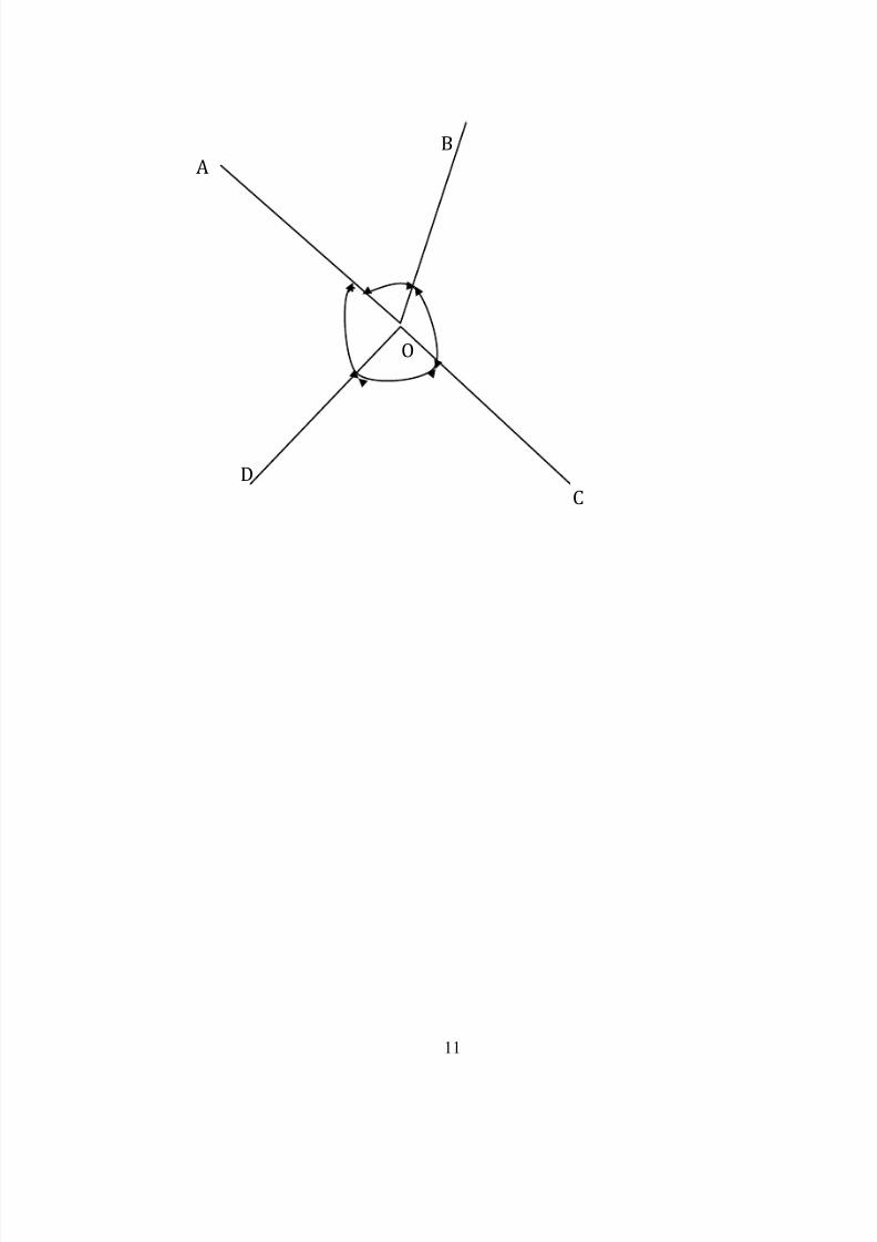
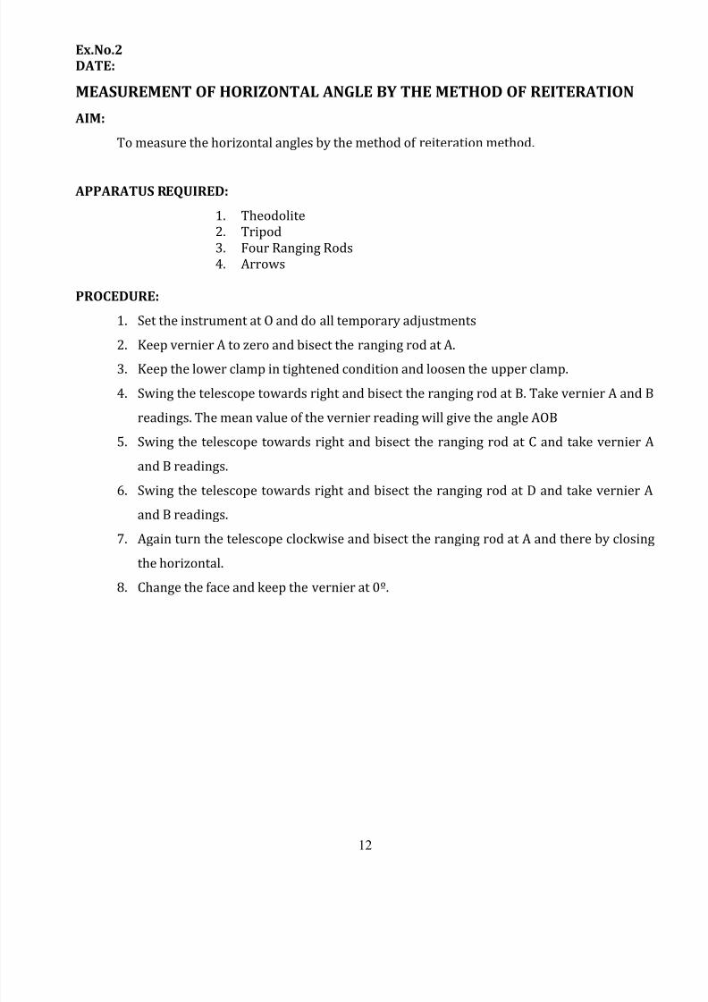
MEASUREMENT OF HORIZONTAL ANGLE BY THE METHOD OF REITERATION
AIM:
To measure the horizontal angles by the method of reiteration method.
APPARATUS REQUIRED:
1. Theodolite
2. Tripod
3. Four Ranging Rods
4. Arrows
PROCEDURE:
1. Set the instrument at O and do all temporary adjustments
2.
Keep vernier A to zero and bisect the ranging rod at A.3. Keep the lower clamp in tightened condition and loosen the upper clamp.
4. Swing the telescope towards right and bisect the ranging rod at B. Take vernier A and B
readings. The mean value of the vernier reading will give the angle AOB
5. Swing the telescope towards right and bisect the ranging rod at C and take vernier A
and B readings.
6. Swing the telescope towards right and bisect the ranging rod at D and take vernier A
and B readings.
7. Again turn the telescope clockwise and bisect the ranging rod at A and there by closing
the horizontal.
8. Change the face and keep the vernier at 0º.
8/12/2019 Surveying II Manual 21.11.13
http://slidepdf.com/reader/full/surveying-ii-manual-211113 13/61
13
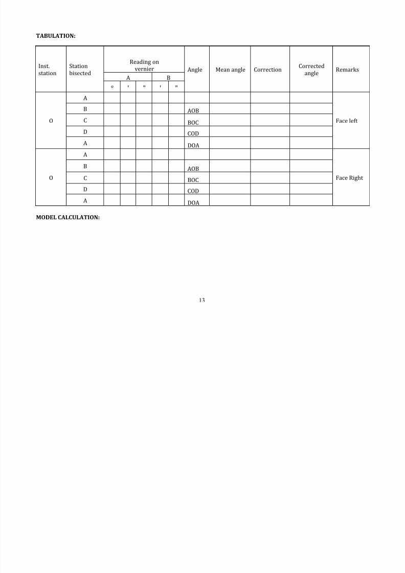
TABULATION:
Inst.
station
Station
bisected
Reading on
vernier Angle Mean angle CorrectionCorrected
angleRemarks
A B
° ' " ' "
O
A
Face left
B AOB
C BOC
D COD
A DOA
O
A
Face Right
B AOB
C BOC
D COD
A DOA
MODEL CALCULATION:
8/12/2019 Surveying II Manual 21.11.13
http://slidepdf.com/reader/full/surveying-ii-manual-211113 14/61
14
9. Bisect the ranging rod at A keeping the lower clamp tightened. Swing the telescope in
the counter clock direction and bisect the ranging rod at D and note down the readings .
10. Rotating further anticlockwise bisect the ranging rods at C and B, note down the vernier
readings.
11. Finally bisect the ranging road at A and note down the readings. Now the readings must
be same as the initial reading otherwise error should be equally distributed between
the included angles.
RESULT:
The horizontal angles :
Angle AOB = ……………..
Angle BOC = …………….. Angle COD = ……………..
Angle DOA =……………….
8/12/2019 Surveying II Manual 21.11.13
http://slidepdf.com/reader/full/surveying-ii-manual-211113 15/61
15
P Q
O
8/12/2019 Surveying II Manual 21.11.13
http://slidepdf.com/reader/full/surveying-ii-manual-211113 16/61
16
Ex.No.3
DATE:
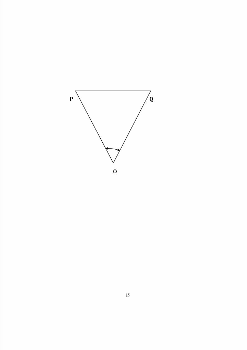
MEASUREMENT OF HORIZONTAL ANGLES BY REPETITION METHOD
AIM:
To measure the horizontal angle at a particular given instrument station by Repetition
method.
INSTRUMENTS REQUIRED:
1. Theodolite
2. Tripod
3. Two Ranging Rods
4. Arrows
PROCEDURE:
The method of repetition is used to measure the horizontal angle to a finer degree ofaccuracy than that obtainable with the least count of the vernier. By this method an angle is
measured two (or) more time by allowed the vernier to remain clamped each time at the end of
each measurement of the previous station. Thus an angle reading is mechanically repetitions. The
average horizontal angle is then obtained by dividing the final reading by number of repetitions.
To measure the angle of horizontal AOB, the following Procedure:
1. Set the instrument at station ‘O’ and level it with the help of alidade bubble and foot screw.
Set zero reading (or) vernierA note the reading at vernier B.
2. Loose the lower clamp and direct the telescope towards the point ‘P’ accurately by lowertangential screw.
3.
Then unclamp the upper clamp and turn the instrument clockwise about inner axistowards ‘Q’ accurately with the upper tangential axis.
4. Unclamped the lower clamp and turn the telescope and sight P. Again bisect ‘P’ accuratelyby using the lower tangential screw. It should be noted that the vernier reading will not be
changed in this operation. Since the upper plate is clamped to the lower.
5. Unclamp the upper clamp, turn the telescope clockwise and Sight ‘Q’ accurately by uppertangent screw.
6. Repeat the process until the angle i.e. for repeated no. of times say three times. The average
angle with face left will be equal to the final reading divided by number of repetition (3).
8/12/2019 Surveying II Manual 21.11.13
http://slidepdf.com/reader/full/surveying-ii-manual-211113 17/61
17
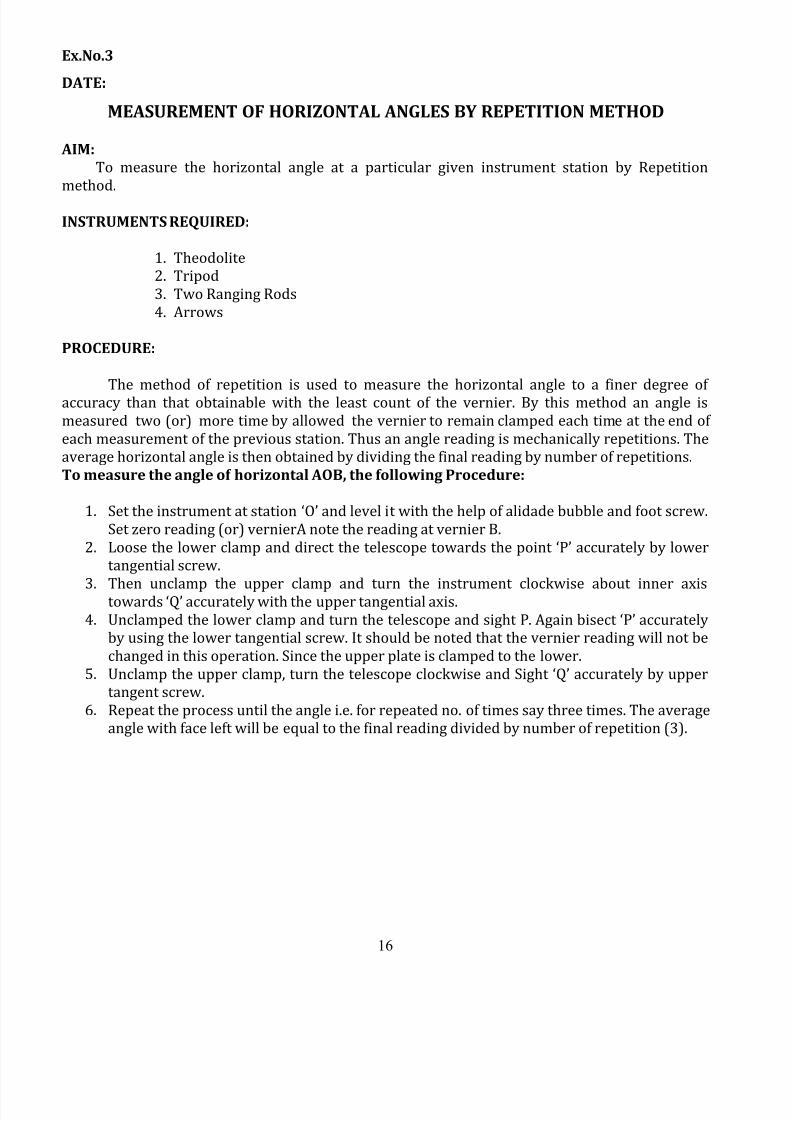
TABULATION:
MODEL CALCULATION:
Inst.
station
Sight
to
Face Left Face Right
Average
Horizontal
angleNo. of
RepetitionReading on
vernier Mean angleReading on
vernier Mean angle
A B A B
° ' " ' " ° ' " ° ' " ' " ° ' " ° ' "
O
P
1Q
P
2Q
P
3Q

8/12/2019 Surveying II Manual 21.11.13
http://slidepdf.com/reader/full/surveying-ii-manual-211113 18/61
18
RESULT:
The average horizontal angle POQ = ..................
8/12/2019 Surveying II Manual 21.11.13
http://slidepdf.com/reader/full/surveying-ii-manual-211113 19/61
19
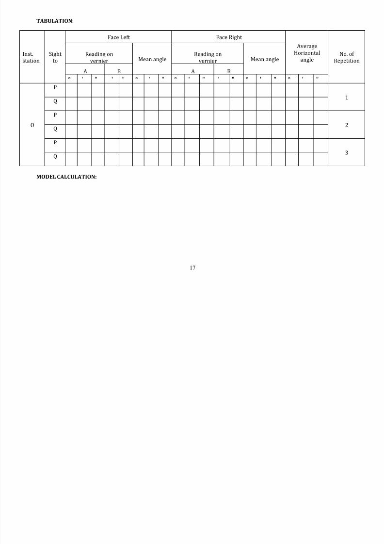
TABULATION:
MODEL CALCULATION:
From the triangle QPQ’
R.L of Q = R.L of B.M + Staff reading on BM + V
V= D tan
Inst.
station
Sight
to
Face Left Face Right
Average
Vertical angle No. of
RepetitionReading on
vernier Mean angleReading on
vernier Mean angle
C D C D
° ' " ' " ° ' " ° ' " ' " ° ' " ° ' "
O
A
1
B
A
2
B
A
3
B
8/12/2019 Surveying II Manual 21.11.13
http://slidepdf.com/reader/full/surveying-ii-manual-211113 20/61
20
Ex.No.4
DATE:
MEASUREMENT OF VERTICAL ANGLE
AIM:
To determine the vertical angle between the top and the bottom of the building and
also find the height of the building.
INSTRUMENT REQUIRED:
1. Theodolite
2. Tripod Stand
3. Chain (or) tape
4. Arrow
PROCEDURE:
1. The instrument fixed over the station and leveled with reference to the alidade
bubble.
2. The telescope clamping screw is loosened C & D verniers to set 0° exactly using
vertical tangent screw. .
3. Turn the telescope and bisect exactly to the staff on B.M. the height of the
instrument measured as “h”.
4. Loosen the telescope clamp screw and the telescope is moved in vertical direction
and object Q is bisected. For exact bisection use vertical circle tangent screw.
5. The vernier reading C and D are noted. The mean value of the vernier C and D gives
the vertical angle ““.
6.
Changing, the faces makes similar observations and mean of vertical angle (face left& face right) ““is noted.
7. The horizontal distance “D” between the base of the object and instrument station ismeasured using tape.
8. Then the height of the building is calculated by using the trigonometrically relations.
RESULT:
The height of the object, h+V = …………....
R.L of Q = …………….
8/12/2019 Surveying II Manual 21.11.13
http://slidepdf.com/reader/full/surveying-ii-manual-211113 21/61
21
Ex.No.5
DATE:
CLOSED THEODOLITE TRAVERSE -
ME ASURING INCLUDED ANGLE
[BALANCING THE TR AVERSE BY GRAPHICAL METHOD]
AIM: To plot the closed theodolites traverse by measuring included angles and then the
error of closure is balanced by Graphical method.
APPARATUS REQUIRED:
1. Transit theodolite
2. Chain
3. Tape
4. Ranging rods
5. Arrows.
PROCEDURE:
1. Setup the Theodolite over the starting station "A"and do the temporary adjustments.
2. Orient the telescope towards the magnetic north and then determine the magnetic
bearing of the initial line AB (i.e., b)
3. Set the vernier A to 0º using lower clamp and tangent screw, take a back sight on
last station "E" using lower clamp and tangent screw (vernier "A" still reads zero).
4. Loosen the upper clamp turn the telescope clockwise and take a foresight on B,
clamp the upper clamp and bisect "B" use upper tangent screw for exact bisection.
Read both verniers the mean for the two verniers is the required included angle EAB
(θ1).5. Change the face, face left to face right and again measure angle EAB (θ1).
6. The average of the two included angles in steps 4 & 5 is the correct included angle
EAB(θ1).
7. Shift the instrument to second station "B" measure the included angle ABC (θ2) by
taking a back sight on "A” and a foresight on "C" as done in steps (3) & (4)8. Similarly measure included angles at C,D& E (i.e.,(θ3) (θ4) & (θ5)).
9. Measure the distances of traverse line in AB, BC, CD, DE & EA using tape or chain.
10. After the completion of field work, it becomes necessary to plot the same. The sum -
of the interior angles ((θ1) + (θ2) + (θ3) + (θ4) + (θ5)) should be equal to (2n - 4) 90°
where n is the number of sides.
8/12/2019 Surveying II Manual 21.11.13
http://slidepdf.com/reader/full/surveying-ii-manual-211113 22/61
22
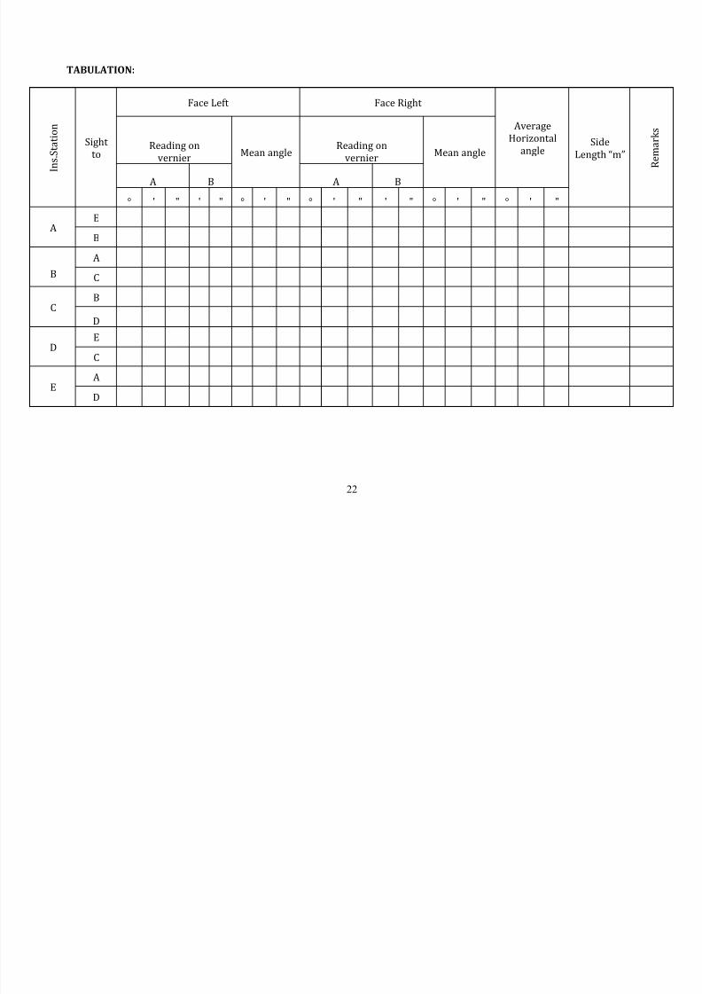
TABULATION:
I n s . S t a t i o n
Sight
to
Face Left Face Right
Average
Horizontal
angleSide
Length “m” R e m a r k s
Reading on
vernierMean angle
Reading on
vernierMean angle
A B A B
° ' " ' " ° ' " ° ' " ' " ° ' " ° ' "
AE
B
B
A
C
CB
D
D
E
C
EA
D
8/12/2019 Surveying II Manual 21.11.13
http://slidepdf.com/reader/full/surveying-ii-manual-211113 23/61
23
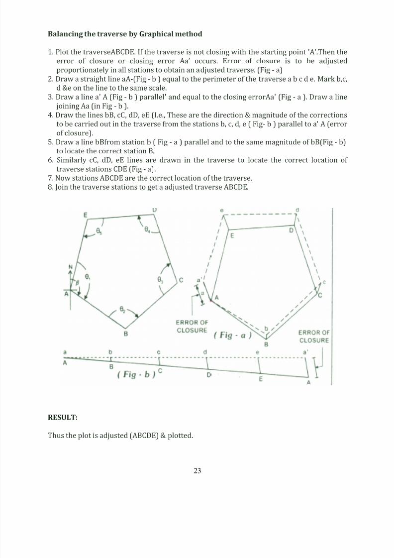
Balancing the traverse by Graphical method
1. Plot the traverseABCDE. If t he traverse is not closing with the st arting point 'A'.Then the
error of closure or closing error Aa’ occurs. Error of closure is t o be adjusted
proportionat ely in all stations to obtain an adjusted traverse. (Fig - a)
2. Draw a straight line aA-(Fig - b ) equal to the perimeter of the traverse a b c d e. Mark b,c,
d &e on the line to the same scale.
3. Draw a line a' A (Fig - b ) parallel' and equal to the closing errorAa' (Fig - a ). Draw a linejoining Aa (in Fig - b ).
4. Draw the lines bB, cC, dD, eE (I.e., These are the direction & magnitude of the corrections
to be carried out in the traverse from t he stations b, c, d, e ( Fig- b ) parallel to a' A (error
of closure).
5. Draw a line bBfrom station b ( Fig - a ) parallel and to the same magnitude of bB(Fig - b)
to locate the correct station B.
6. Similarly cC, dD, eE lines are drawn in the traverse to locate the correct location of
traverse stations CDE (Fig - a).
7. Now stations ABCDE are the correct location of t he t raverse.
8. Join the traverse stations to get a adjusted traverse ABCDE.
RESULT:
Thus the plot is adjusted (ABCDE) & plotted.
8/12/2019 Surveying II Manual 21.11.13
http://slidepdf.com/reader/full/surveying-ii-manual-211113 24/61
24
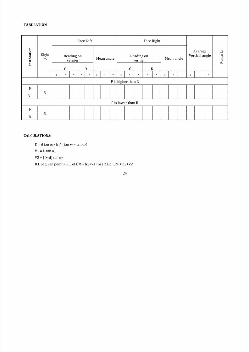
TABULATION
CALCULATIONS:
D = d tan α2 - h / (tan α1 - tan α2)
V1 = D tan α1
V2 = (D+d) tan α2
R.L of given point = R.L of BM + h1+V1 (or) R.L of BM + h2+V2
I n s t . S t a t i o n
Sight
to
Face Left Face Right
Average
Vertical angle
R e
m a r k s
Reading on
vernier
Mean angleReading on
vernier
Mean angle
C D C D
° ' " ' " ° ' " ° ' " ' " ° ' " ° ' "
P is higher than R
PQ
R
P is lower than R
PQ
R
8/12/2019 Surveying II Manual 21.11.13
http://slidepdf.com/reader/full/surveying-ii-manual-211113 25/61
25
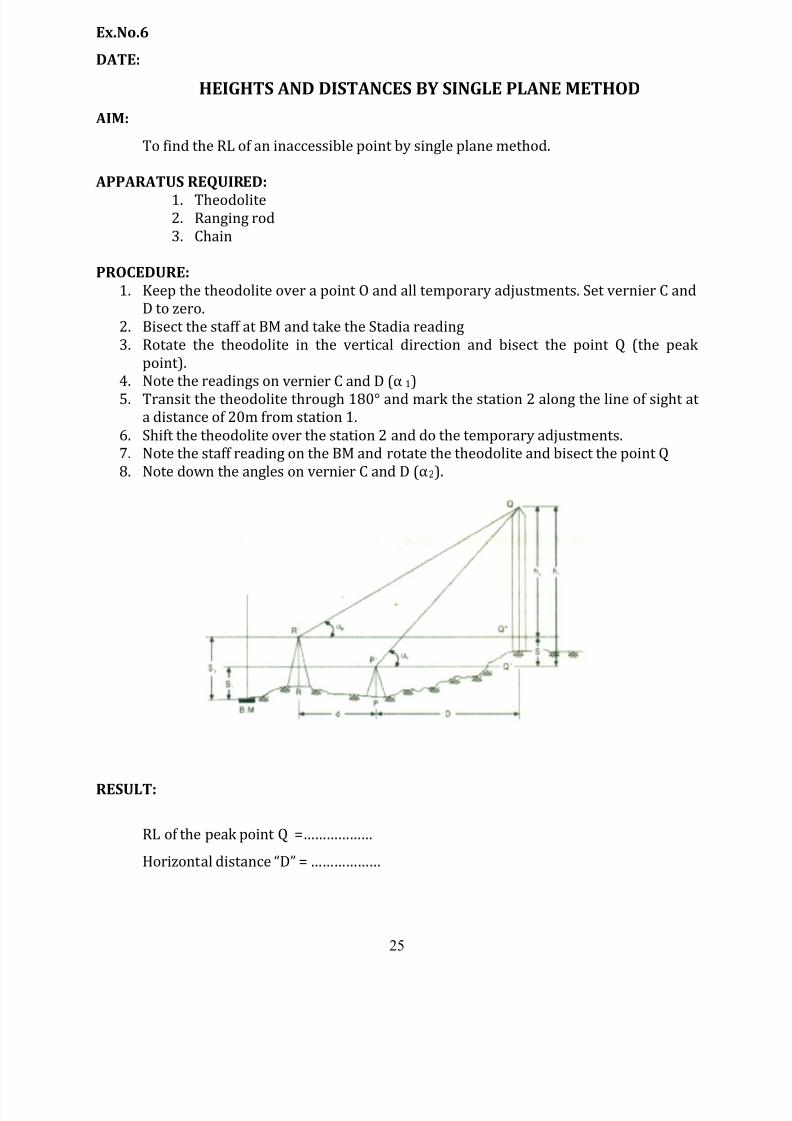
Ex.No.6
DATE:
HEIGHTS AND DISTANCES BY SINGLE PLANE METHOD
AIM:
To find the RL of an inaccessible point by single plane method.
APPARATUS REQUIRED:
1. Theodolite2. Ranging rod
3. Chain
PROCEDURE:
1. Keep the theodolite over a point O and all temporary adjustments. Set vernier C and
D to zero.
2. Bisect the staff at BM and take the Stadia reading
3. Rotate the theodolite in the vertical direction and bisect the point Q (the peak
point).
4. Note the readings on vernier C and D (α 1)
5. Transit the theodolite through 180° and mark the station 2 along the line of sight at
a distance of 20m from station 1.
6. Shift the theodolite over the station 2 and do the temporary adjustments.
7. Note the staff reading on the BM and rotate the theodolite and bisect the point Q
8. Note down the angles on vernier C and D (α2).
RESULT:
RL of the peak point Q =………………
Horizont al distance “D” = ………………
8/12/2019 Surveying II Manual 21.11.13
http://slidepdf.com/reader/full/surveying-ii-manual-211113 26/61
26
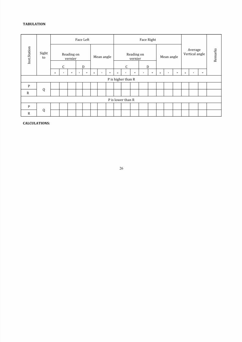
TABULATION
CALCULATIONS:
I n s t . S t a t i o n
Sight
to
Face Left Face Right
Average
Vertical angle
R e
m a r k s
Reading on
vernier
Mean angleReading on
vernier
Mean angle
C D C D
° ' " ' " ° ' " ° ' " ' " ° ' " ° ' "
P is higher than R
PQ
R
P is lower than R
PQ
R
8/12/2019 Surveying II Manual 21.11.13
http://slidepdf.com/reader/full/surveying-ii-manual-211113 27/61
27
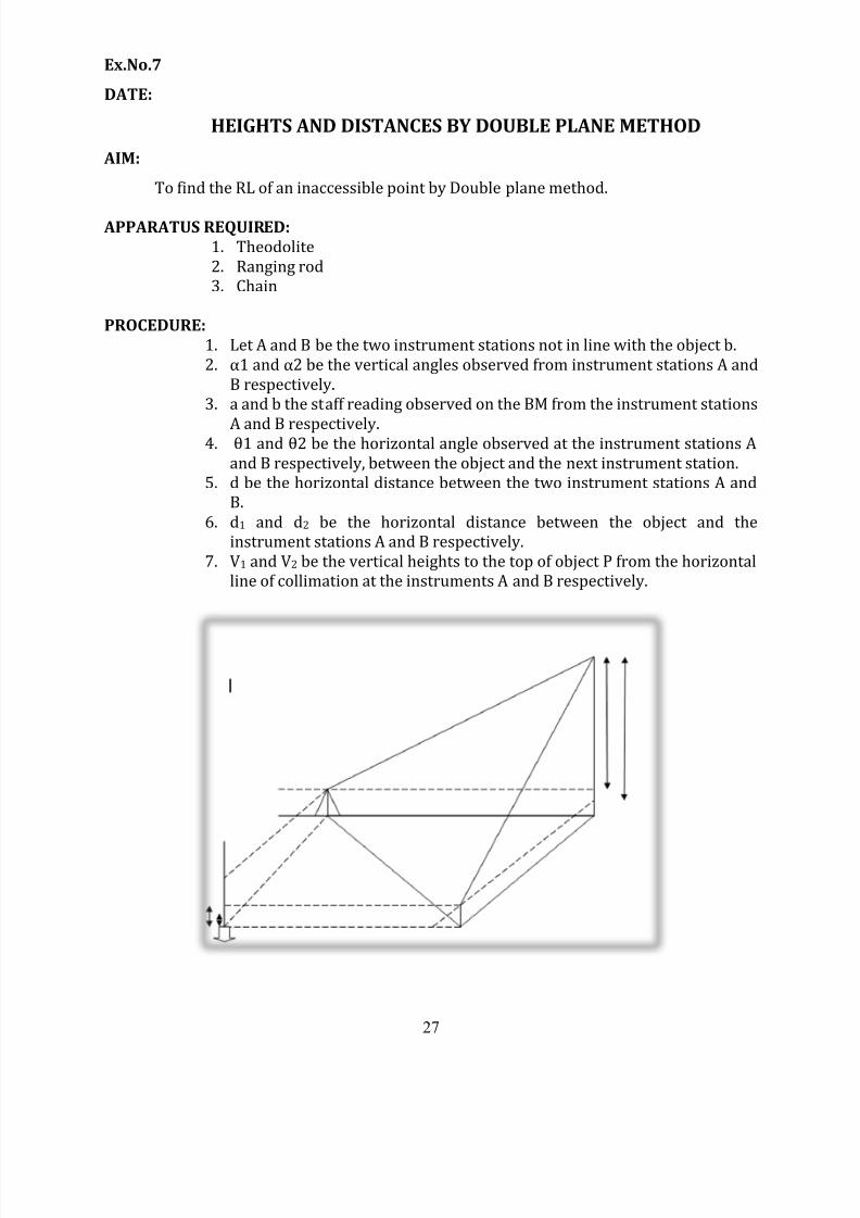
Ex.No.7
DATE:
HEIGHTS AND DISTANCES BY DOUBLE PLANE METHOD
AIM:
To find the RL of an inaccessible point by Double plane method.
APPARATUS REQUIRED:
1. Theodolite
2. Ranging rod
3. Chain
PROCEDURE:
1. Let A and B be the two instrument stations not in line with the object b.
2. α1 and α2 be the vertical angles observed from instrument stations A and
B respectively.
3. a and b the staff reading observed on the BM from the instrument stations
A and B respectively.4. θ1 and θ2 be the horizontal angle observed at the instrument stations A
and B respectively, between the object and the next instrument station.
5. d be the horizontal distance between the two instrument stations A and
B.
6. d1 and d2 be the horizontal distance between the object and the
instrument stations A and B respectively.
7. V1 and V2 be the vertical heights to the top of object P from the horizontal
line of collimation at the instruments A and B respectively.
8/12/2019 Surveying II Manual 21.11.13
http://slidepdf.com/reader/full/surveying-ii-manual-211113 28/61
28
CALCULATION:
P’ be the base of the object P.
In ∆APB
Angle P’AB=θ1; Angle P’BA=θ2; AB=d
AP’=d1; BP’=d2
AP’B=180O – (Angle P’AB+ P’BA=θ2)
=180O –(θ1+θ2) =θ3
Using sine rule we can write
In above Equation expect d1 and d2 others are known
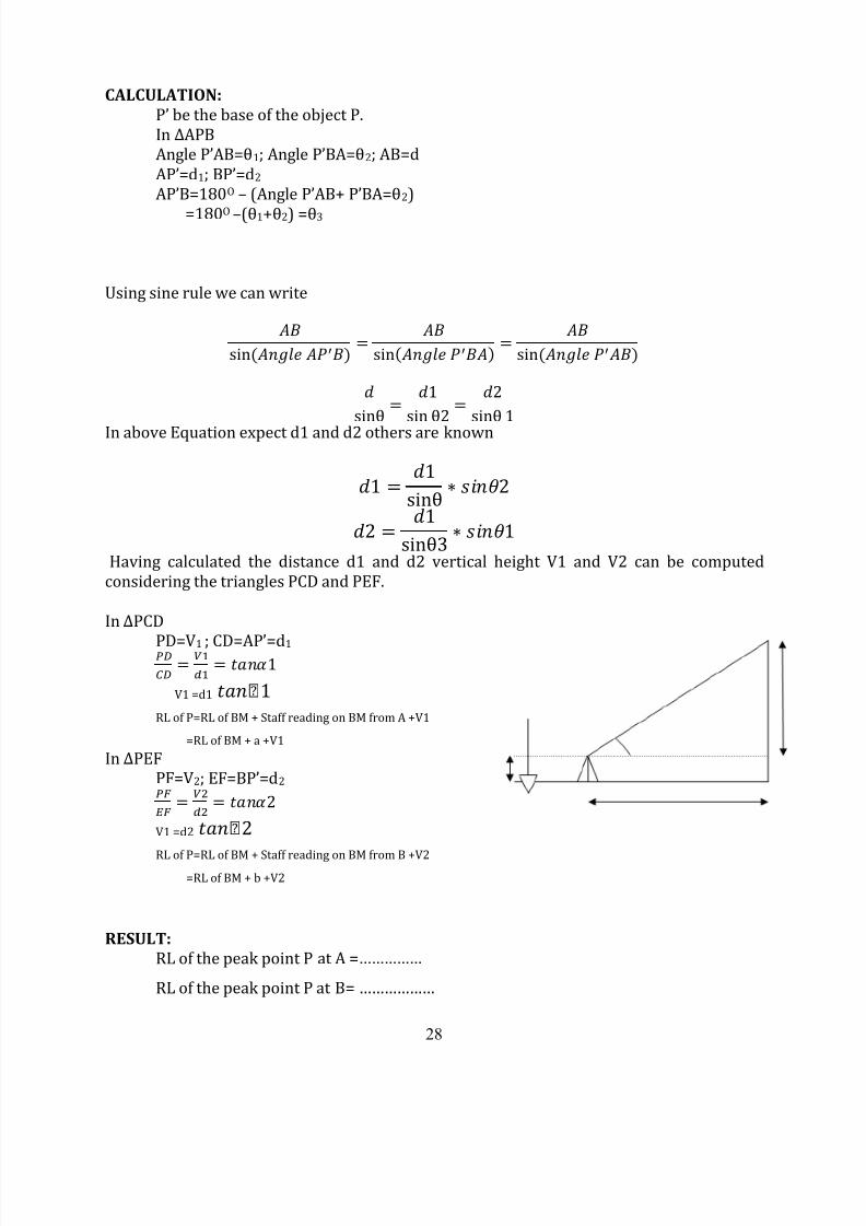
Having calculated the distance d1 and d2 vertical height V1 and V2 can be computed
considering the triangles PCD and PEF.
In ∆PCD
PD=V1 ; CD=AP’=d1
V1 =d1
RL of P=RL of BM + Staff reading on BM from A +V1
=RL of BM + a +V1
In ∆PEFPF=V2; EF=BP’=d2
V1 =d2
RL of P=RL of BM + Staff reading on BM from B +V2=RL of BM + b +V2
RESULT:
RL of the peak point P at A =……………
RL of the peak point P at B= ………………
8/12/2019 Surveying II Manual 21.11.13
http://slidepdf.com/reader/full/surveying-ii-manual-211113 29/61
29
Ex.No.8
DATE:
TANGENTIAL TACHEOMETRY
AIM:
To find the Reduced level of a point Q and the distance between two given points P and
Q.
APPARATUS REQUIRED:
1. Theodolite
2. Levelling staff
PROCEDURE:
1. Setup the instrument at point ‘P’ and center the instrument. Level the instrument with
the help of foot screws and the bubble tubes.
2. Keep the staff at the Bench mark and note down the axial hair reading. Let it be ‘h’. 3. Direct the theodolite towards point Q. Keep the leveling staff at point ‘Q’. Mark the two
readings on the leveling staff such that the distance between the two readings is 1m andlet it be ‘S’.
4. Sight the top reading marked in the leveling staff and note down the vertical angle, with
reference to horizontal. Let it be ‘1’.
5. Similarly sight the bottom reading marked in the staff and note down the vertical angle
with reference to the horizontal and let it be ‘2’.
6. Calculate the distance ‘D’ and vertical distance‘V’ using the formula,
if 1 and 2 are angles of elevation,
D = S/ (tan 1- tan 2) and V = D tan 2
If α1 and α2 are angles of depression,
D = S/ (tan α2 – α1) and V = D tan α2
If one is angle of depression and the other is angle of elevation,
D = S/ (tanα1 + tanα2) and V = D tan α2
Reduced level of point Q = R.L of P + h + V – r.
Where,
r is the axial hair reading noted down at point ‘Q’.
8/12/2019 Surveying II Manual 21.11.13
http://slidepdf.com/reader/full/surveying-ii-manual-211113 30/61
30
TABULATION:
Instrument
Station
Staff
station
Vertical
Angle θ
Staff Readings (m)Reduced Level of
B.M (m)
Middle
Inst.
station
Sight
to
Face Left Face Right
Average
Vertical angle
R
e m a r k s
Reading on
vernier Mean angleReading on
vernier Mean angle
C D C D
° ' " ' " ° ' " ° ' " ' " ° ' " ° ' "
P Q

8/12/2019 Surveying II Manual 21.11.13
http://slidepdf.com/reader/full/surveying-ii-manual-211113 31/61
31
CALCULATION:
Staff intercept = S = 2-1 = 1m
Vertical angle at 1m = α1 =
Vertical angle at 2m = α2 =
Horizontal distance D = S/ (tan α2 – α1)
Vertical distance V = D tan α2
Reduced level of point Q = R.L of P + h + V – r.
RESULT:
(i) Reduced level of point Q = ……………….
(ii) Distance between the two points P and Q =………
8/12/2019 Surveying II Manual 21.11.13
http://slidepdf.com/reader/full/surveying-ii-manual-211113 32/61
32
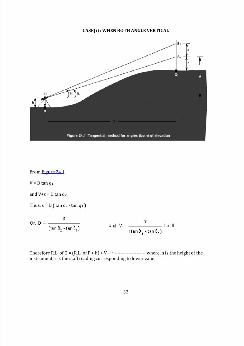
CASE(i) : WHEN BOTH ANGLE VERTICAL
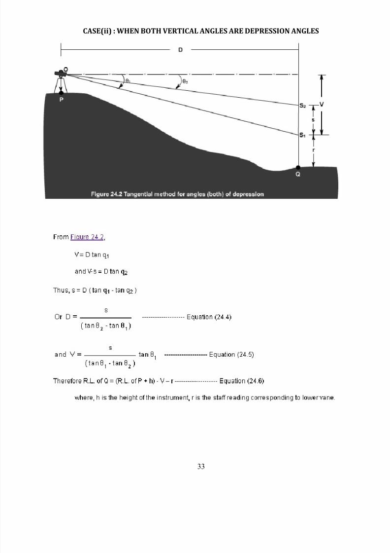
From Figure 24.1,
V = D tan q1
and V+s = D tan q2
Thus, s = D ( tan q2 - tan q1 )
Therefore R.L. of Q = (R.L. of P + h) + V – r -------------------- where, h is the height of the
instrument, r is the staff reading corresponding to lower vane.
8/12/2019 Surveying II Manual 21.11.13
http://slidepdf.com/reader/full/surveying-ii-manual-211113 33/61
33
CASE(ii) : WHEN BOTH VERTICAL ANGLES ARE DEPRESSION ANGLES
8/12/2019 Surveying II Manual 21.11.13
http://slidepdf.com/reader/full/surveying-ii-manual-211113 34/61
34
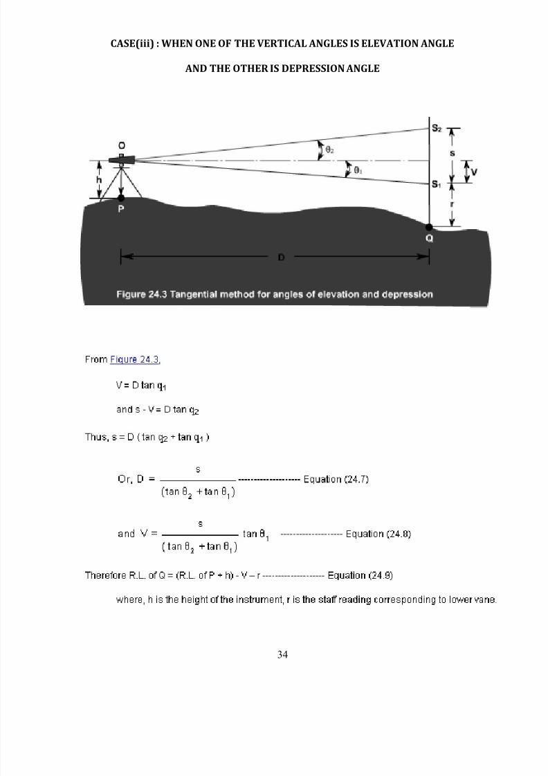
CASE(iii) : WHEN ONE OF THE VERTICAL ANGLES IS ELEVATION ANGLE
AND THE OTHER IS DEPRESSION ANGLE
8/12/2019 Surveying II Manual 21.11.13
http://slidepdf.com/reader/full/surveying-ii-manual-211113 35/61
35
Ex.No.9
DATE:
STADIA TACHEOMETRY
AIM:
To determine the Reduced level of point ‘P’, when the Reduced level of point ‘Q’ is given.
APPARATUS REQUIRED:
1. Theodolite,
2. Leveling staff.
PROCEDURE:
1. Set up the theodolite and center the instrument over point ‘P’ and make initial leveling
adjustments using the foot screws and bubble tube.
2. Keep the staff on the bench mark and note down the axial hair reading on the staff with
line of sight, horizontal, to determine the height of instrument.
3.
Direct the telescope to the point ‘Q’ and note down the staff readings and the verticalangle subtended by the line of sight with the horizontal.
4. Calculate the distance between the points ‘P’ and ‘Q’ by using the formula, D = KS
Cos2, Where D is the distance between the two points, S is the staff intercept at ‘Q’ and
is the vertical angle.
5. Reduced level of point ‘Q’ = R.L of Benchmark + Axial hair reading at BM+ V – r. Where V
is the vertical intercept at ‘Q’ and r is the axial hair reading at ‘Q’.
8/12/2019 Surveying II Manual 21.11.13
http://slidepdf.com/reader/full/surveying-ii-manual-211113 36/61
36
TABULATION:
Instrument
Station
Staff
station
Vertical
Angle θ
Staff Readings (m) Reduced
Level of
B.M (m)Top Middle Lower
Inst.
station
Sight
to
Face Left Face Right
Average
Vertical angle
R e m
a r k s
Reading on
vernier Mean angleReading on
vernier Mean angle
C D C D° ' " ' " ° ' " ° ' " ' " ° ' " ° ' "
8/12/2019 Surveying II Manual 21.11.13
http://slidepdf.com/reader/full/surveying-ii-manual-211113 37/61
37
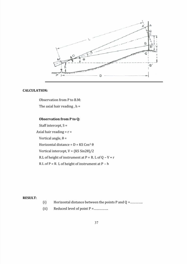
CALCULATION:
Observation from P to B.M:
The axial hair reading , h =
Observation from P to Q:
Staff intercept, S =
Axial hair reading = r =
Vertical angle, θ =
Horizontal distance = D = KS Cos2 θ
Vertical intercept, V = (KS Sin2θ)/2
R.L of height of instrument at P = R. L of Q – V + r
R.L of P = R. L of height of instrument at P – h
RESULT:
(i) Horizontal distance between the points P and Q =…………..
(ii) Reduced level of point P =…………….
8/12/2019 Surveying II Manual 21.11.13
http://slidepdf.com/reader/full/surveying-ii-manual-211113 38/61
38
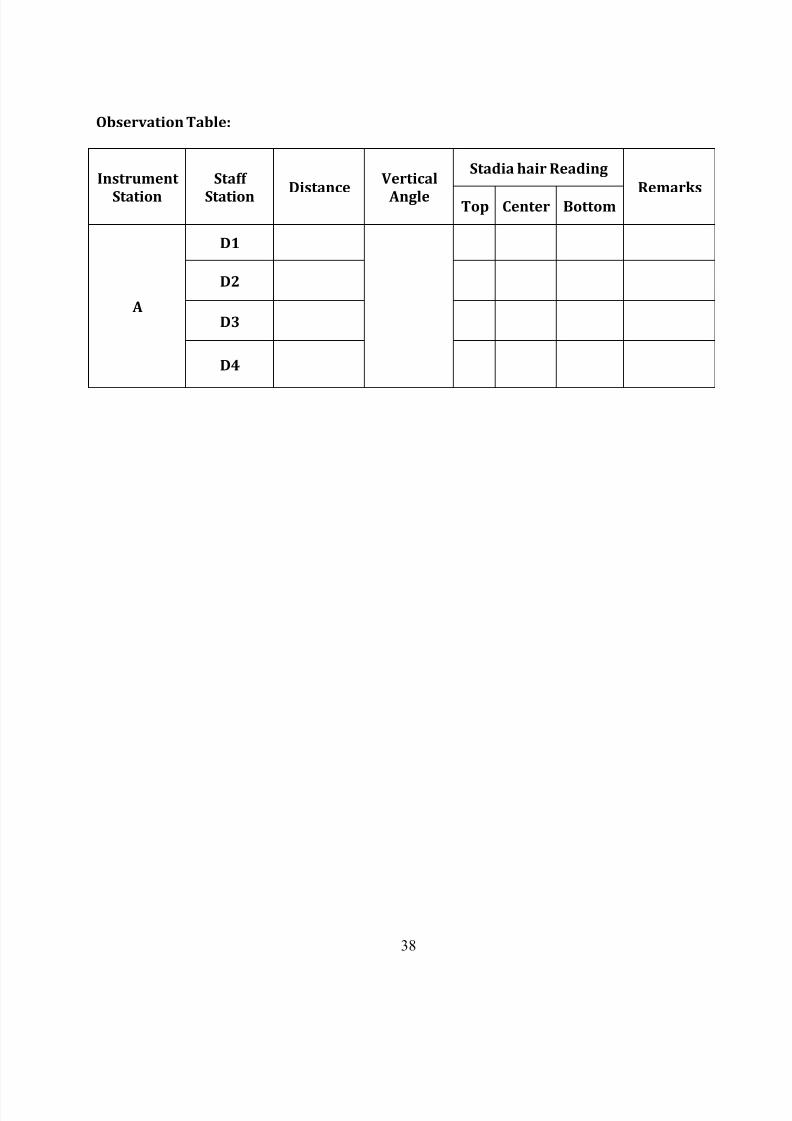
Observation Table:
Instrument
Station
Staff
StationDistance
Vertical
Angle
Stadia hair Reading
Remarks
Top Center Bottom
A
D1
D2
D3
D4
8/12/2019 Surveying II Manual 21.11.13
http://slidepdf.com/reader/full/surveying-ii-manual-211113 39/61
39
Ex.No.10
DATE:
DETERMINATION OF THE MULTIPLYING AND ADDITIVE CONSTANT
AIM:
Determination of the Multiplying and additive constant of given Tachometer
APPARATUS:
1. Tachometer with tripod,
2. Tape
3. Leveling staff
4. Wooden pegs
5. Ranging rods
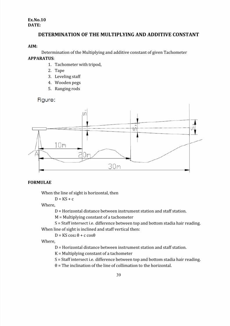
FORMULAE
When the line of sight is horizontal, then
D = KS + c
Where,
D = Horizontal distance between instrument station and staff station.
M = Multiplying constant of a tachometer
S = Staff intersect i.e. difference between top and bottom stadia hair reading.
When line of sight is inclined and staff vertical then:D = KS cos2 θ + c cosθ
Where,
D = Horizontal distance between instrument station and staff station.
K = Multiplying constant of a tachometer
S = Staff intersect i.e. difference between top and bottom stadia hair reading.
θ = The inclination of the line of collimation to the horizontal.
8/12/2019 Surveying II Manual 21.11.13
http://slidepdf.com/reader/full/surveying-ii-manual-211113 40/61
40
c = The additive constant of the tachometer
DETERMINATION OF CONSTANT K AND CThe values of the multiplying constant k and the additive constant C can be computed
by the following methods:
1st METHOD:
In this method ,the additive constant C=(f +d) is measured from the instruments while
the multiplying constant k is computed from field observations
1) Focus the instruments to a distant object and measure along the telescope the
distance between the objective and crosshair.
Since f1 is very large in this case ,f is approximately equal to f2 i.e , equal to the
distance of the diaphragm from the objective.
2) The distance d between the instrument axis and the objective is variable in case of
external focusing telescope, being greater for short sights and smaller for long sights. It should,
therefore, be measured for average sight. Thus, the additive constant (f +d) is known.
3) To calculate the multiplying constant k, measure a known distance and take the S1 on
the staff kept at that point , the line of sight being horizontal. Using equation
For the average value, staff intercepts, s2, s3 etc., can be measured corresponding
to distance d2, d3 etc., and mean value can be calculated.
2nd METHOD:
In this method, both the constants are determined by field observations as under:
1) Measure a line, about 200 m long on fairly level ground and drive pegs at some
intervals, say 50 meters.
2) Keep the staff on the pegs and observe the corresponding staff intercepts with
horizontal sight.
3) Knowing the values of d and s for different points, a number of simultaneousequations can be formed by substituting the values of d and s in equation (1.1). the
simultaneous solution of successive pairs of equations will give the values of k and c, and the
average of these can be found. If s1 is the staff intercept corresponding to distance D1 and s2
corresponding to D2, we have,
8/12/2019 Surveying II Manual 21.11.13
http://slidepdf.com/reader/full/surveying-ii-manual-211113 41/61
41
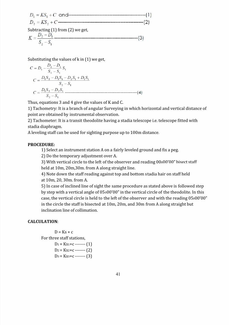
Subtracting (1) from (2) we get,
Substituting the values of k in (1) we get,
Thus, equations 3 and 4 give the values of K and C.
1) Tachometry: It is a branch of angular Surveying in which horizontal and vertical distance of
point are obtained by instrumental observation.2) Tachometer: It is a transit theodolite having a stadia telescope i.e. telescope fitted with
stadia diaphragm.
A leveling staff can be used for sighting purpose up to 100m distance.
PROCEDURE:
1) Select an instrument station A on a fairly leveled ground and fix a peg.
2) Do the temporary adjustment over A.
3) With vertical circle to the left of the observer and reading 00000’00” bisect staff
held at 10m, 20m,30m. from A along straight line.
4) Note down the staff reading against top and bottom stadia hair on staff held
at 10m, 20, 30m. from A.
5) In case of inclined line of sight the same procedure as stated above is followed step
by step with a vertical angle of 05000’00” in the vertical circle of the theodolite. In this
case, the vertical circle is held to the left of the observer and with the reading 05000’00”
in the circle the staff is bisected at 10m, 20m, and 30m from A along straight but
inclination line of collimation.
CALCULATION:
D = Ks + c
For three staff stations,
D1 = Ks1+c ------- (1)
D2 = Ks2+c ------- (2)
D3 = Ks3+c ------- (3)
8/12/2019 Surveying II Manual 21.11.13
http://slidepdf.com/reader/full/surveying-ii-manual-211113 42/61
42
As ; s1, s2, s3 can be known solving (1) &(2), (2) & (3) , (1) & (3) to get 3 values of m & c
,then average of three values is required answer.
D = Ks cos2 θ + c cosθ
For, three station the equations are;
D1 = Ks1 cos2 θ1 + C cosθ1 ------- (1)
D2 = Ks2 cos2 θ2 + C cosθ2------- (2)
D3 = Ks3 cos2 θ3 + C cosθ3------- (3)
As ; s1, s2, s3 can be known solving (1) &(2), (2) & (3) , (1) & (3) to get 3 valuesof K & C ,then average of three values is required answer.
RESULT:
A) For horizontal line of collimation; 1) The additive constant ‘c’ for a given tacheometer is found out to be ---------
2) The multiplying constant ‘m’ for a given tacheometer is found to be ---------
B) For inclination line of collimation;
1) The additive constant ‘c’ for a given tacheometer is found out to be ----------
2) The multiplying constant ‘k’ for a given tacheometer is found to be ---------
8/12/2019 Surveying II Manual 21.11.13
http://slidepdf.com/reader/full/surveying-ii-manual-211113 43/61
43
8/12/2019 Surveying II Manual 21.11.13
http://slidepdf.com/reader/full/surveying-ii-manual-211113 44/61
44
Ex.No.11
DATE:
SETTING OUT WORK – FOUNDATION MARKING
AIM:
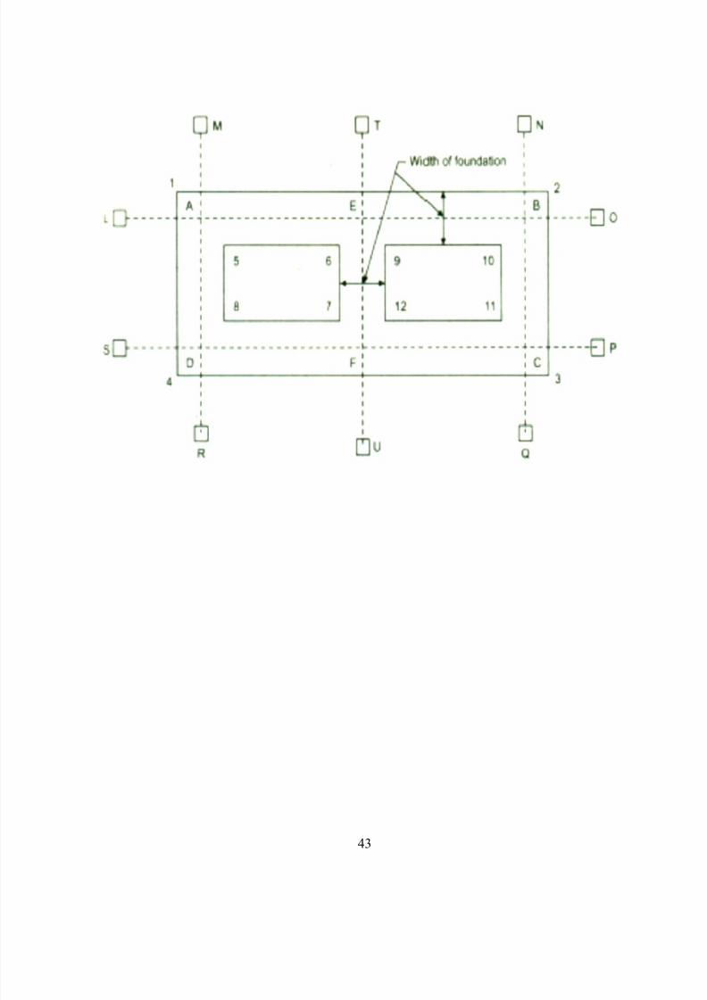
To set out the centerlines for the Foundation walls of the buildings and mark the
lines for excavation.
APPARATUS REQUIRED:1. Tape or chain.
2. Cross staff.
3. Ranging rod.
4. Arrows.
5. String.
PROCEDURE:
1. Prepare a centre line sketch of the building (indicate the centre of cross walls also).
2. Remove any vegetation in the construction site.
3. Set out the baseline with reference to given any reference points.4. Mark the ends of the cent re line of the walls, point s A and B from the base line.
5. As the end marks A, B, C, et c. disturbed during excavat ion, stakes (or masonry pillars) are
fixed at L, M, N,etc., a little away (about 2 to 3 m) for end mark and tie a string accurat ely.
6. Mark the centre line for all other walls AD, BC, etc. by dropping perpendicular. For small
buildings the perpendiculars may be setout by using a chain or a tape by'3-4-5' method.
For aimportant and big building when sides are long a theodolite may be employed t o
accurat ely set out the perpendiculars and to range t he lines.
7. For every wall drive the pegs a lit t le away f or end mark and tie a string accurately.
8. Measure the diagonals and check with t heir corresponding calculated lengt hs.
9. Mark the width of foundation from t he centre line and fix up the corners 1,2,3,4,5, etc.,
pegs are driven at t hese corners, the chord is stretched and lime is spread along t hechords.
10. Now the trench plan being marked on the ground, excavation may be started.
RESULT:
The centerline and foundation mark to be excavated has been set out.
8/12/2019 Surveying II Manual 21.11.13
http://slidepdf.com/reader/full/surveying-ii-manual-211113 45/61
45
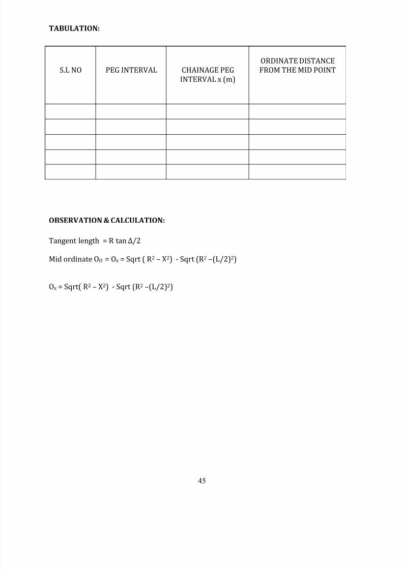
TABULATION:
S.L NO PEG INTERVAL CHAINAGE PEG
INTERVAL x (m)
ORDINATE DISTANCE
FROM THE MID POINT
OBSERVATION & CALCULATION:
Tangent length = R tan Δ/2
Mid ordinate OO = Ox = Sqrt ( R2 – X2) - Sqrt (R2 –(L/2)2)
Ox = Sqrt( R2 – X2) - Sqrt (R2 –(L/2)2)
8/12/2019 Surveying II Manual 21.11.13
http://slidepdf.com/reader/full/surveying-ii-manual-211113 46/61
46
Ex.No.12
DATE:
SETTING OUT CURVES BY LONG CHORD METHOD
AIM:
To set out a simple curve using Long Chord method.
APPARATUS REQUIRED:
1. Chain
2. Arrows
3. Ranging rods and
4. Cross Staff.
PROCEDURE:
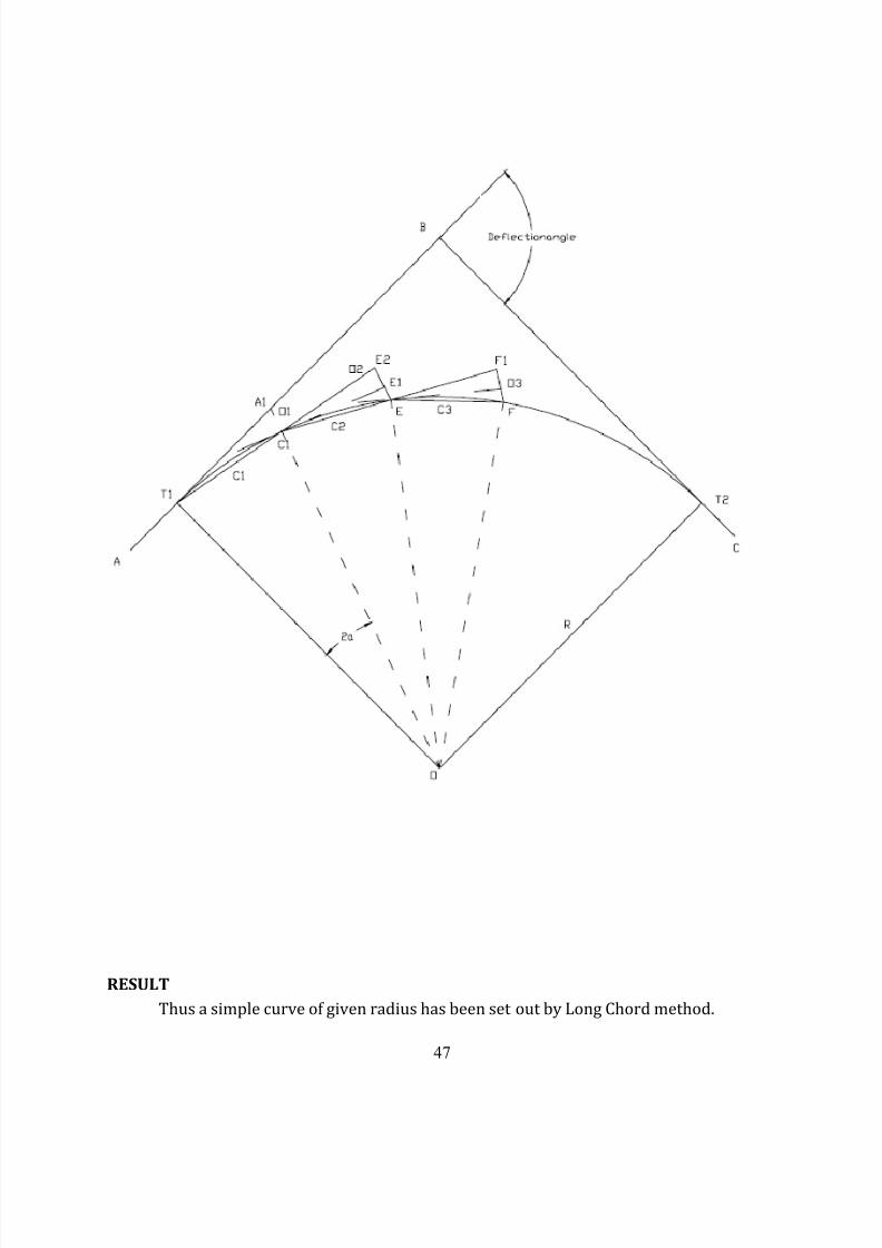
1. Curves are generally used or highways and railways it is necessary to change the
direction of motion. A curve may be circular, parabolic or spherical.
2. To sets the curve by using offset from long chord method. First we must know the
radius of curvature and the deflection angle. Now tangential length is calculated byusing the formula.
3. Now keeping the theodolite levelled on tripod and keeping a point as a reference
deflection angle is marked on the ground.
4. Length of long chord is calculated by using the formula.
5. By chaining and ranging method, the length of long chord is marked on the ground.
6. The distance x1, x2…. Are measured from the mid of the long chord.
7. Ordinate distances which is calculated from the formula,
Ox = Sqrt( R2 – X2) - Sqrt (R2 –(L/2)2)
Are erected on the ground with the help of staff and tape.
8. Similarly for all the points the ordinates are measured joining them all will give a
smooth curve.
8/12/2019 Surveying II Manual 21.11.13
http://slidepdf.com/reader/full/surveying-ii-manual-211113 47/61
47
RESULT
Thus a simple curve of given radius has been set out by Long Chord method.
8/12/2019 Surveying II Manual 21.11.13
http://slidepdf.com/reader/full/surveying-ii-manual-211113 48/61
48
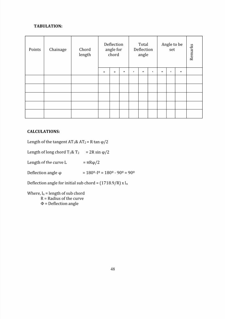
TABULATION:
Points Chainage Chord
length
Deflection
angle for
chord
Total
Deflection
angle
Angle to be
set
R e m a r k s
° ° " ' " ' " ' "
CALCULATIONS:
Length of the tangent AT1& AT2 = R tan φ/2
Length of long chord T1& T2 = 2R sin φ/2
Length of the curve L = πRφ/2
Deflection angle φ = 180º-Iº = 180º - 90º = 90º
Deflection angle for initial sub chord = (1718.9/R) x ln
Where, ln = length of sub chord
R = Radius of the curve
Φ = Deflection angle
8/12/2019 Surveying II Manual 21.11.13
http://slidepdf.com/reader/full/surveying-ii-manual-211113 49/61
49
Ex.No.13
DATE:
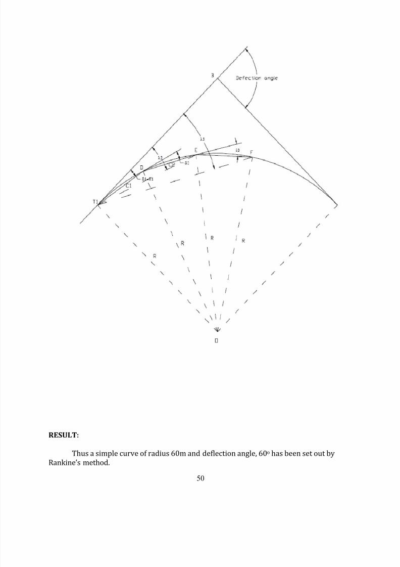
SETTING OUT A SIMPLE CURVE BY RANKINE’S METHOD
AIM:
To set out a simple curve of radius 60m and deflection angle of 60o by Rankine’s
tangential angle method.
APPARATUS REQUIRED:
1. Theodolite,
2. Ranging rods,
3. Chain and arrows.
PROCEDURE:
1. Setup the theodolite at the point of curve(T1) with both the plates clamped to zero.
Direct the theodolite to bisect the point of intersection (V).The line of sight is then in
the direction of the rear tangent.2. Fix the first deflection angle(1) in the horizontal circle and now the theodolite is
directed towards T1A.
3. Now, hold the zero end of the tape at T1 and hold an arrow at a distance of T1A (i.e.
the first chord length). Swing the tape around T1 till the arrow is bisected by the
cross hairs. Thus the first point ‘A’ is fixed.
4. Set the second deflection angle (2) in the horizontal circle and repeat the same
procedure, as done for the first deflection angle and fix the second point ‘B’.
5. And the same procedure are to be adopted for other deflection angles also and other
points on the curve are fixed.
8/12/2019 Surveying II Manual 21.11.13
http://slidepdf.com/reader/full/surveying-ii-manual-211113 50/61
50
RESULT:
Thus a simple curve of radius 60m and deflection angle, 60o has been set out by
Rankine’s method.
8/12/2019 Surveying II Manual 21.11.13
http://slidepdf.com/reader/full/surveying-ii-manual-211113 51/61
51
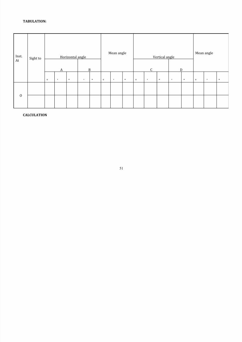
TABULATION:
CALCULATION
Inst.
At Sight toHorizontal angle
Mean angleVertical angle
Mean angle
A B C D
° ' " ' " ° ' " ° ' " ' " ° ' "
O
8/12/2019 Surveying II Manual 21.11.13
http://slidepdf.com/reader/full/surveying-ii-manual-211113 52/61
52
Ex.No.14
DATE:
DETERMINATION OF AZIMUTH OF THE LINE BY
EXTRAMERIDIAN OBSERVATION ON THE SUN
AIM:
Let OP be a line whose azimuth ( fore bearing) is to be determined by taking
extrameridian observation on the sun.
APPARATUS REQUIRED:
1) Theodolite
2) Ranging rod
PROCEDURE:
1. Set up the instrument at O, and make all temporary adjustment.
2. Keep the vernier A at 0º.
3. Sight the ranging rod P for bisecting the rod using lower tangent screw for
necessary.
4. Release the upper clamp and direct the telescope to the sun and note down linevertical angle , the sun first quadrant by upper tangential screw and Vertical
tangent screw.
5. Next being to image of the sun III quadrant the down, the time for vertical angle 2
.Note down the horizontal angle θ2also.
a) Indian standard time observation t n = t 1 + t 2 / 2.
b) Altitude of the sun of the time of observation, = 1 + 2 / 2
c) GMT of observation = t – 5 h 30 min
d) Declination of the sun of the GMT = sqrtSin (S-Z)x sin (S-C)
Sin (S-P) x sin S
S = (Z + C + P)/2
e) Average horizontal angle between OP and OS is θ = (θ1 + θ2)/2
f) Azimuth of line OP = True bearing of DA = θ -
PRINCIPLE AND SIGNIFICANCE:
The required altitude and the horizontal angles are those to the sun centre. Hence
the hairs should be set tangential to the two limbs simultaneously. The opposite limbs are
then observed by chaining the face.
RESULT:
The azimuth of line OP = ……………
8/12/2019 Surveying II Manual 21.11.13
http://slidepdf.com/reader/full/surveying-ii-manual-211113 53/61
53
Ex.No:15
DATE:
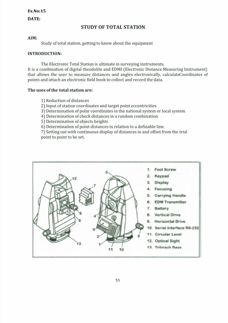
STUDY OF TOTAL STATION
AIM:
Study of total station, getting to know about the equipment
INTRODUCTION:
The Electronic Total Station is ultimate in surveying instruments.
It is a combination of digital t heodolite and EDMI (Electronic Distance Measuring Instrument)
that allows the user to measure distances and angles electronically, calculateCoordinates of
points and attach an electronic field book to collect and record the data.
The uses of the total station are:
1) Reduction of distances
2) Input of station coordinates and target point eccentricities
3) Determination of polar coordinates in the national system or local system4) Determination of check distances in a random combination
5) Determination of objects heights
6) Determination of point distances in relation to a definable line.
7) Setting out with continuous display of distances in and offset from the trial
point to point to be set .
8/12/2019 Surveying II Manual 21.11.13
http://slidepdf.com/reader/full/surveying-ii-manual-211113 54/61
54
ON-SITE SET-UP
a) Place Tripod firmly into the soil and raise legs to a comfortable height . The Telescope of
the Total Station should be approximately at eye height or slightly lower. Make
allowance for the instrument height once it is attached. Take into account that multiple
people "Will be using the Total Station through the day and adjust the station height to
the eye-height of the shortest group member. The Tripod cannot be moved during a
measurement session so get it right the first time.
b) Use leg height adjustments to visually level the top surface of the Tripod. Check with the
bull's-eye level of your Brunton compass.
c) Remove Tribrach (13) from instrument by rotating the black lever on the Tribrach
counterclockwise until freed from the Tripod. Mount the Tribrach on the Tripod with
large aluminum screw. Insure you do not strip the threads.
d) Verify that the three foot-screws (1) are in a neutral position (near center). This will
allow for the greatest range of adjustments.
e) Using the three foot-screws (1), level the Tribrach (13) using the bulls eye level on the
Tribrach.
f) Mount the Total Station to the Tribrach base (13) and secure by rotating latch
clockwise.
g) Turn on the Total Station
h) Press Menu
i)
Go to Level
j) Release the Horizontal Drive gross adjustment screw (9)
k) Rotate the Total Station so that the Eyepiece of the Telescope is between two of the
three foot-screws. Using only these two foot -screws, level the instrument as indicated
on the Total Station display. (off level and level images will be inserted)
l) Rotate the Total Station one third of a turn and repeat using the next pair of foot screws.
Repeat again for the third and final combination of two foot-screws. Then repeat all
three combinations in the same order until perfectly level.
m) Press the ESC key.
n) Measure and record the instrument height using the small Indentation on the right side
of the Total Station. Set the Prism Rod to match the instrument height .
o) Have one person walk out at least 10 meters due north, the farther the better. Using a
properly declinatedBrunton compass, shoot a bearing from the Prism rod to the total

8/12/2019 Surveying II Manual 21.11.13
http://slidepdf.com/reader/full/surveying-ii-manual-211113 55/61
55
Station. Adjust the Prism Rod position until the bearing is due south. Rotate the Total
Station and sight the Prism. The Total Station should now be facing due north. It is
critical during this step that the Prism rod is exactly vertical and that the cross-hair in
the Total Station Optical Sight is exactly in the center of the Prism.
p) Press the Menu key, go to set Horizontal. Set the Horizontal angle to zero and press
enter. Finally, press enter once again to return to the measurement screen.
q) The Total Station is now ready to take measurements.
8/12/2019 Surveying II Manual 21.11.13
http://slidepdf.com/reader/full/surveying-ii-manual-211113 56/61
56
EX.NO:16
DATE :
MEASUREMENTS OF DISTANCE AND CO-ORDINATES OF GIVEN POINTS
AIM:
To measure the distances and coordinate of the given points using the total station.
APPARATUS REQUIRED:
1. Total station with tripod
2. Prism with telescopic stand
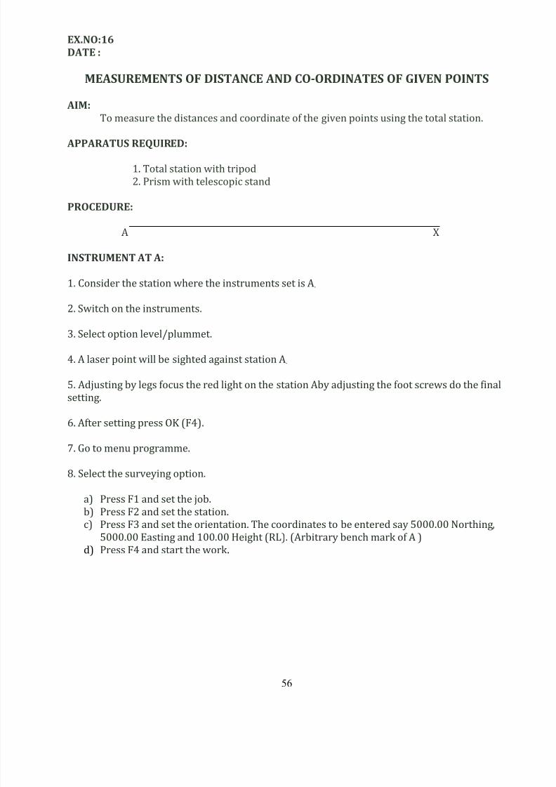
PROCEDURE:
A X
INSTRUMENT AT A:
1. Consider the station where the instruments set is A .
2. Switch on the instruments.
3. Select option level/plummet.
4. A laser point will be sighted against station A.
5. Adjusting by legs focus the red light on the station Aby adjusting the f oot screws do the final
setting.
6. After setting press OK (F4).
7. Go to menu programme.
8. Select the surveying option.
a) Press F1 and set the job.
b) Press F2 and set the station.
c) Press F3 and set the orientation. The coordinates to be entered say 5000.00 Northing,
5000.00 Easting and 100.00 Height (RL). (Arbitrary bench mark of A )
d) Press F4 and start the work .
8/12/2019 Surveying II Manual 21.11.13
http://slidepdf.com/reader/full/surveying-ii-manual-211113 57/61
57
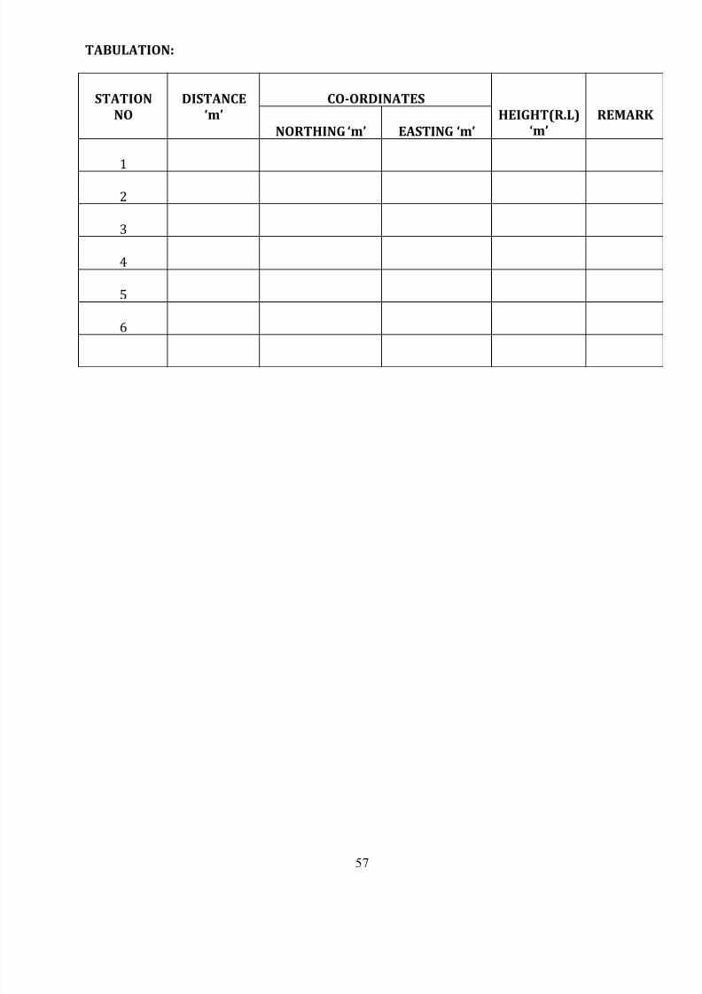
TABULATION:
STATION
NO
DISTANCE
‘m’
CO-ORDINATES
HEIGHT(R.L)
‘m’
REMARK
NORTHING ‘m’ EASTING ‘m’
1
2
3
4
5
6
8/12/2019 Surveying II Manual 21.11.13
http://slidepdf.com/reader/full/surveying-ii-manual-211113 58/61
58
INSTRUMENT AT X:
a. Place the prism rod at the given point X.
b. Sight the telescope to the prism viewing through focusing ring and adjust to sight .the
prism with the horizontal and vertical drives for fine adjust to align cross hair in to the
centre of the prism.
c. Press F1 (Distance) after sighting the given point X.
d. Now distance will be displayed in the screen. Eg. 80.474 m.
e. Press the button page, the coordinates, and the height of the station X,will be displayed
on the screen. Eg. East: 3839.974 m, North: 5057.665 m and height 101.933m.
f. Now press, the button REC to record the details as displayed in the Item (d) and (e)
g. Repeat the steps (a) to (f) and sight the other 5 given stations and record the distance ,
coordinate and height of the locations similarly.
RESULT:
The distances and coordinate are =………………
8/12/2019 Surveying II Manual 21.11.13
http://slidepdf.com/reader/full/surveying-ii-manual-211113 59/61
59
Ex.No.17
DATE:
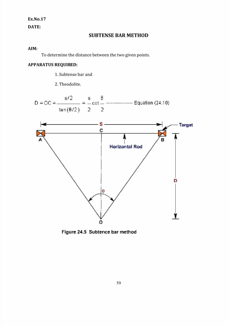
SUBTENSE BAR METHOD
AIM:
To determine the distance between the two given points.
APPARATUS REQUIRED:
1. Subtense bar and
2. Theodolite.
8/12/2019 Surveying II Manual 21.11.13
http://slidepdf.com/reader/full/surveying-ii-manual-211113 60/61
60
PROCEDURE:
1. Setup the subtense bar at one of the given points. Level the instrument with the help of
the bubble tube and foot screws. Let the length of the subtense bar be‘s’. 2. Keep a telescope in between the two arms of the subtense bar and locate a line which is
perpendicular to the subtense bar.
3. Along the perpendicular line, set up the theodolite at the other given point.
4. Center the instrument over that point and do the initial levelling adjustments.
5. Direct the telescope towards the marking in any one arm of the subtense bar and set the
horizontal circle in the theodolite at 0-0.
6. Rotate the theodolite in the horizontal direction till the vertical cross hair coincides
with the marking in the other arm of the subtense bar.
7. Note down the horizontal angle in the horizontal circle of the theodolite. Let it be β.8. The distance between the two points can be calculated using the formula,
D = (s * 206265)/β if β is in seconds.
D = s/ (2* tan β/2) if β is in radians.
8/12/2019 Surveying II Manual 21.11.13
http://slidepdf.com/reader/full/surveying-ii-manual-211113 61/61
TABULATION:
Instrument StationSubtended angle (β)
In secondsDistance (m)
CALCULATION:
S =
=
D = (S * 206265)/β


![Civil IV Surveying II [10cv44] Solution](https://cdn.vdocuments.us/doc/165x107/55cf96b3550346d0338d3a7d/civil-iv-surveying-ii-10cv44-solution.jpg)