Supply Current Harmonics Control Using
Multipulse Converters Rinki Jain Deependra Singh, Monesh Jain S.A.T.I. Vidisha Lect, ASCT Bhopal [email protected], [email protected] [email protected], ABSTRACT:-
The three phase multipulse AC-DC
converters are developed for improving
power quality at dc output side and ac
input side. This dissertation deals with
input current shaping of uncontrolled
and controlled rectifier using Multipulse
current shaping concept. The topology
referred to as the multipulse converter,
used as a modular structure where each
power module comprises of a three
phase bridge rectifier (controlled or
uncontrolled), a transformer for 12 pulse
converter and AC and DC side LC
filters. Rectifier used is 6 pulse and 12
pulse uncontrolled and controlled
converter. The performance
improvement of multipulse converter is
achieved in terms of supply power
factor, total harmonics distortion (THD)
in supply current and dc voltage ripples.
Effect of filter in output voltage and
current of inverter is presented in terms
of their THD. Investigations have been
made for different values of LC filter
elements on output current, output
voltage, and supply current and ripple in
dc component. These results confirms
according to IEEE Standard 519-1992.
WHAT ARE MULTIPULSE AC-DC
CONVERTERS
Multi pulse converters are converters
providing more than six pulses of DC
voltage per cycle from AC input. Or the
converter having more steps in AC input
current than that of six pulse bridge
rectifier supply current. Bridge rectifier
is the basic block required for AC- DC
conversion, however , full- wave and
half wave rectifier are also used up to
120kW ratings. Phase shifting
transformers are used to derive multiple
phase supply from three-phase AC
mains using different combinations of
transformer windings such as star, delta,
zigzag, fork, polygon, etc.
The following are multi-pulse converter
are used in paper:
(1) 6 Pulse Converters

(2) 12 Pulse Converters
SIX PULSE DOIDE CONVERTER
In multiples converters server six
pulse diode rectifier all diodes are
connected in parallel. Each rectifier fed
by phase shifted secondary windings
voltages of a transformer to shape the
primary current close to sinusoidal. As
compared to a six - pulse rectifier the
transformer primary current in a
multipulse converter is shaped using
time displaced step wave shaped.
Increasing the number of rectifier raises
the number of steps in the primary
current wave from & produces a sinusoidal
shaped supply current flowing into the
transformer primary winding.
The three - Phase input supply voltage (Van,
Vbn, Vcn) without line impedance drop
could be expresses as
)3.(....................3
2sinVV
)2.(....................3
2sinVV
)1.(..............................sinVV
mcn
mbn
man
t
t
t
The voltage at the input of rectifier (Vsa,
Vsb, and Vsc) can be expressed in equation.
)6.........(..........dt
discL-RsiscVV
)5.......(..........dt
disbL-RsisbVV
)4.......(..........dt
disaL-RsisaVV
scnsc
sbnsb
sansa
The derivative of the load current is:
)7(....................LL2
iRR2V
dt
di
Ls
LLsLLSL
The three phase supply currents
(isa, isb, isc) can be determined for this the
input currents for six conduction
intervals of diode pairs (D1D2, D2D3,
D3D4, D4D5, D5D6 and D6D1) with 600
duration for an interval.
D1
VO
D3 D5
D4 D6 D2
A
BC
Figure: 3-Ø six pulse diode converter
Figure: Voltage waveform for 3- Ø 6-
pulse converter
SIMULATION & RESULT
The simulation block of three-phase
six-pulse diode is shown in further
figures. It consists of three phase ac
source to supply .The line voltage are
Vab, Vbc & Vca.
A RL load is connected across the six-
pulse diode converter. The result can be
visualized through the scope.
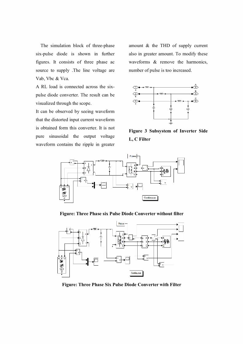
It can be observed by seeing waveform
that the distorted input current waveform
is obtained form this converter. It is not
pure sinusoidal the output voltage
waveform contains the ripple in greater
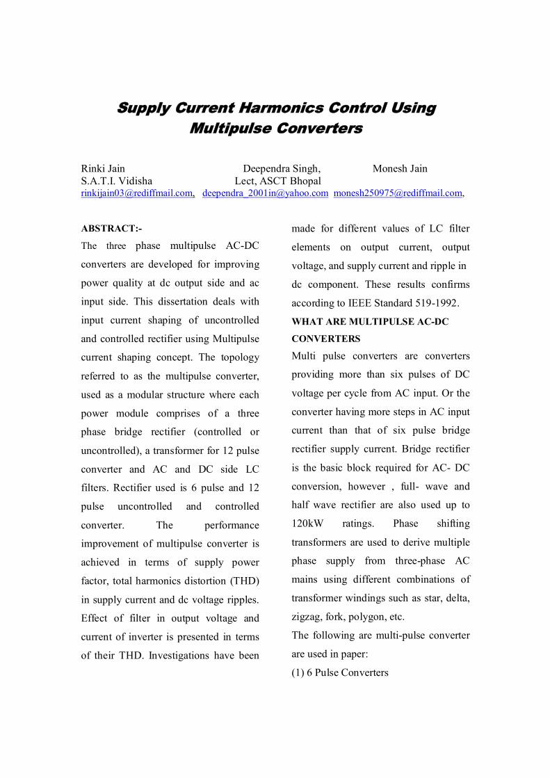
amount & the THD of supply current
also in greater amount. To modify these
waveforms & remove the harmonics,
number of pulse is too increased.
Figure 3 Subsystem of Inverter Side
L, C Filter
Figure: Three Phase six Pulse Diode Converter without filter
Figure: Three Phase Six Pulse Diode Converter with Filter

6-pulse uncontrolled converter
Effect of different output voltage waveform with and without filter
0.45 0.46 0.47 0.48 0.49 0.5-1000
-500
0
500
1000
Time (s)
volta
ge
0 10 20 30 40 500
20
40
60
80
100
Harmonic order
Fundamental (50Hz) = 507.3 , THD= 52.56%
Mag
(% o
f Fun
dam
enta
l)
0 10 20 300
5
10
15
20
25
30
Harmonic order
Fundamental (50Hz) = 507.3 , THD= 52.56%
Mag (
% of
Fund
amen
tal)
(a) Output voltage without filter
0.45 0.46 0.47 0.48 0.49 0.5-1000
-500
0
500
1000
Time (s)
volta
ge
0 10 20 30 40 500
20
40
60
80
100
Harmonic order
Fundamental (50Hz) = 523.3 , THD= 4.08%
Mag
(% o
f Fun
dam
enta
l)
0 10 20 300
1
2
3
Harmonic order
Fundamental (50Hz) = 522.8 , THD= 5.20%
Mag
(% o
f Fun
dam
enta
l)
(b) Output voltage after filter L= 0.5mH, C=700 µf
0.45 0.46 0.47 0.48 0.49 0.5-1000
-500
0
500
1000
Time (s)
volta
ge
0 10 20 30 40 500
20
40
60
80
100
Harmonic order
Fundamental (50Hz) = 511.9 , THD= 13.10%
Mag
(% o
f Fun
dam
enta
l)
0 10 20 300
2
4
6
8
10
Harmonic order
Fundamental (50Hz) = 511.1 , THD= 14.14%
Mag (
% of
Fun
dame
ntal)
(c) Output voltage after filter L= 0.5mH, C=250 µf
0.45 0.46 0.47 0.48 0.49 0.5-1000
-500
0
500
1000
Time (s)
voltg
e
0 10 20 30 40 500
20
40
60
80
100
Harmonic order
Fundamental (50Hz) = 538.5 , THD= 2.17%
Mag
(% o
f Fun
dam
enta
l)
0 10 20 300
0.5
1
1.5
Harmonic order
Fundamental (50Hz) = 538.7 , THD= 2.25%
Mag
(% o
f Fun
dam
enta
l)
(d)Output voltage before filter L= 1mH, C=700 µf
Figure: Different Waveform of Output Voltage of 6- Pulse Controlled Converter (a) Output voltage without filter (b) Output voltage with filter L=0.5mH, C=700 µf (c) Output voltage with filter L=0.5mH, C=250 µf (d) Output voltage with filter L=1mH, C =700 µf
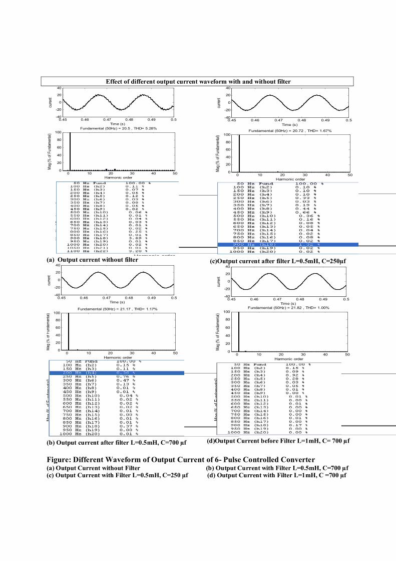
Effect of different output current waveform with and without filter
0.45 0.46 0.47 0.48 0.49 0.5-40
-20
0
20
40
Time (s)
curre
nt
0 10 20 30 40 500
20
40
60
80
100
Harmonic order
Fundamental (50Hz) = 20.5 , THD= 5.28%
Mag
(% o
f Fun
dam
enta
l)
0 10 20 300
1
2
3
4
Harmonic order
Fundamental (50Hz) = 20.5 , THD= 5.28%
Mag (
% of
Fun
dame
ntal)
(a) Output current without filter
0.45 0.46 0.47 0.48 0.49 0.5-40
-20
0
20
40
Time (s)
curr
ent
0 10 20 30 40 500
20
40
60
80
100
Harmonic order
Fundamental (50Hz) = 21.17 , THD= 1.17%
Mag
(%
of F
unda
men
tal)
0 10 20 300
0.2
0.4
0.6
0.8
Harmonic order
Fundamental (50Hz) = 21.17 , THD= 1.08%
Mag
(% o
f Fun
dam
enta
l)
(b) Output current after filter L=0.5mH, C=700 µf
0.45 0.46 0.47 0.48 0.49 0.5-40
-20
0
20
40
Time (s)
curre
nt
0 10 20 30 40 500
20
40
60
80
100
Harmonic order
Fundamental (50Hz) = 20.72 , THD= 1.67%
Mag
(% o
f Fun
dam
enta
l)
0 10 20 300
0.5
1
Harmonic order
Fundamental (50Hz) = 20.72 , THD= 1.77%
Mag (
% o
f Fun
dame
ntal)
(c)Output current after filter L=0.5mH, C=250µf
0.45 0.46 0.47 0.48 0.49 0.5-40
-20
0
20
40
Time (s)
curre
nt
0 10 20 30 40 500
20
40
60
80
100
Harmonic order
Fundamental (50Hz) = 21.82 , THD= 1.00%
Mag
(% o
f Fu
ndam
enta
l)
0 10 20 300
0.2
0.4
0.6
0.8
1
Harmonic order
Fundamental (50Hz) = 21.82 , THD= 1.00%
Mag
(% o
f Fun
dam
enta
l)
(d)Output Current before Filter L=1mH, C= 700 µf
Figure: Different Waveform of Output Current of 6- Pulse Controlled Converter (a) Output Current without Filter (b) Output Current with Filter L=0.5mH, C=700 µf (c) Output Current with Filter L=0.5mH, C=250 µf (d) Output Current with Filter L=1mH, C =700 µf

TWELVE PULSE DOIDE CONVERTER
In the proposed converter circuits Multiples
rectifiers could be connected either in parallel or
in series. The choice of series or parallel
connection depends upon the load voltage
requirement. To connect multiple rectifier units
in a multiples converter circuit, a transformer
with a single primary and multiple isolated
secondary winding is needed. A configuration
(simple, zigzag, and/or multiple sections) of
secondary windings in the transformer magnetic
cores ensures windings produces leading voltage
and the remaining half produces logging voltage
with respect to that of primary winding voltage.
The windings are divided into two equal
numbers to produce the desisted leading &
lagging voltage with respect to primary winding
voltage.
LOAD
iD1
A1
B1C1
A2
C2 B2
iD2
A
CB
D1
VO1
VO2
VO
IP
D'1 D'3 D'5
D'4 D'6 D'2
D3 D5
D4 D6 D2
Figure: Twelve Pulse Diode Converter
with Star Connection Primary
0.7 0.705 0.71 0.715 0.72 0.725 0.73 0.735 0.74 0.745 0.75-400
-300
-200
-100
0
100
200
300
400
time
vs / is
phase difference between voltage and current
Figure: Phase Difference between Voltage and Current in 12-Pulse Uncontrolled Converter
SIMULATION & RESULT
The simulation block of three phase twelve
pulse diode is shown in further figures. It consists
of three phase ac source to supply .The line
voltage are Vab, Vbc & Vca.
Two six pulse diode bridge is connected to the
three phase supply. This is universal thyristor
bridge. The input of these converters is taken from
the output of YgY & YgD transformer. This
configuration provides the phase shift of 30
degrees between the two converters. A RL load is
connected across the six pulse thyristor converter.
The result can be visualized through the scope.
The simulation block of three phase twelve pulse
thyristor is shown in further figures. It consists of
three phase ac source to supply .The line voltage
are Vab, Vbc & Vca. Two six pulse thyristor
bridge is connected to the three phase supply. The
result can be visualized through the scope. It can
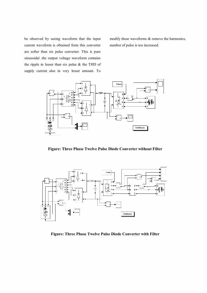
be observed by seeing waveform that the input
current waveform is obtained form this converter
are softer than six pulse converter. This is pure
sinusoidal .the output voltage waveform contains
the ripple in lesser than six pulse & the THD of
supply current also in very lesser amount. To
modify these waveforms & remove the harmonics,
number of pulse is too increased.
Figure: Three Phase Twelve Pulse Diode Converter without Filter
Figure: Three Phase Twelve Pulse Diode Converter with Filter

12-pulse uncontrolled converter
Effect of different output voltage waveform with and without filter
0.45 0.46 0.47 0.48 0.49 0.5-400
-200
0
200
400
Time (s)
volta
ge
0 10 20 30 40 500
20
40
60
80
100
Harmonic order
Fundamental (50Hz) = 335.1 , THD= 52.57%
Mag
(% o
f Fun
dam
enta
l)
0 10 20 300
10
20
30
Harmonic order
Fundamental (50Hz) = 335.1 , THD= 52.57%
Mag
(% o
f Fun
dam
enta
l)
(a)Output voltage without filter
0.45 0.46 0.47 0.48 0.49 0.5-400
-200
0
200
400
Time (s)
volta
ge
0 10 20 30 40 500
20
40
60
80
100
Harmonic order
Fundamental (50Hz) = 343.9 , THD= 4.25%
Mag
(% o
f Fun
dam
enta
l)
0 10 20 300
0.5
1
1.5
2
2.5
3
Harmonic order
Fundamental (50Hz) = 343.4 , THD= 4.73%
Mag (
% of
Fun
dame
ntal)
(b) Output voltage with filter with filter L=0.5mH,
C=700 µf
0.45 0.46 0.47 0.48 0.49 0.5-400
-200
0
200
400
Time (s)
Output voltage with filter (L=1mH, C=700uf)
volta
ge
0 10 20 30 40 500
20
40
60
80
100
Harmonic order
Fundamental (50Hz) = 351.6 , THD= 2.55%
Mag
(% o
f Fun
dam
enta
l)
Time (s)
0 10 20 300
0.5
1
1.5
2
Harmonic order
Fundamental (50Hz) = 351.7 , THD= 2.66%
Mag (
% of
Fun
dame
ntal)
(c) Output voltage with filter with filter L=0.5mH, C=250 µf
0.45 0.46 0.47 0.48 0.49 0.5-500
0
500
Time (s)
volta
ge
0 10 20 30 40 500
50
100
Harmonic order
Fundamental (50Hz) = 339.7 , THD= 6.15%
Mag
(% o
f Fun
dam
enta
l)
0 10 20 300
1
2
3
4
Harmonic order
Fundamental (50Hz) = 339.6 , THD= 6.14%
Mag (
% of
Fun
dame
ntal)
(b) Output voltage with filter with filter L=1mH, C=700 µf
Figure: Different Waveform of Output voltage of 12- Pulse Controlled Converter (a) Output Voltage without Filter (b) Output Voltage with Filter L=0.5mH, C=700 µf (c) Output Voltage with Filter L=0.5mH, C=250 µf (d) Output Voltage with Filter L=1mH, C=700 µf
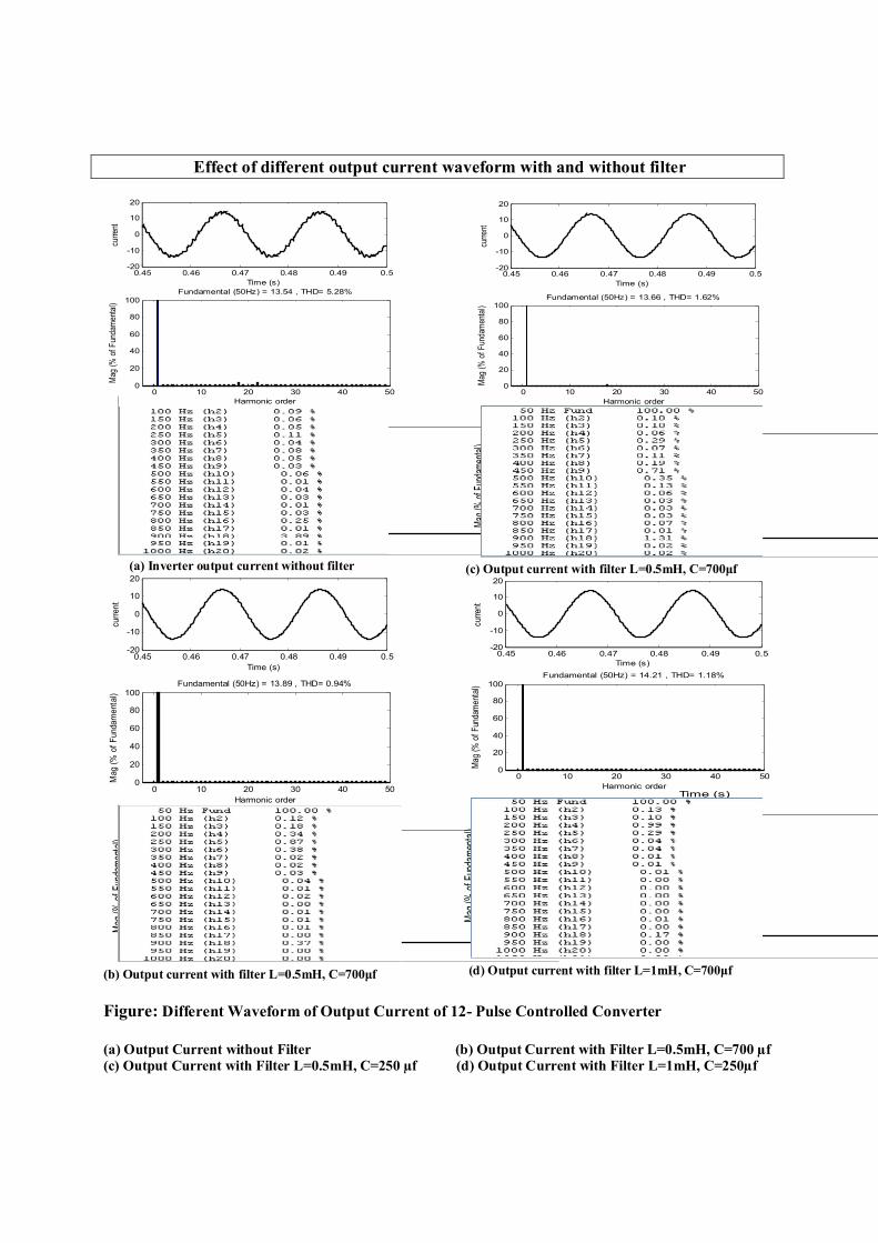
Effect of different output current waveform with and without filter
0.45 0.46 0.47 0.48 0.49 0.5-20
-10
0
10
20
Time (s)
curre
nt
0 10 20 30 40 500
20
40
60
80
100
Harmonic order
Fundamental (50Hz) = 13.54 , THD= 5.28%
Mag
(%
of F
unda
men
tal)
0 10 20 300
1
2
3
4
Harmonic order
Fundamental (50Hz) = 13.54 , THD= 5.28%
Mag
(% o
f Fun
dam
enta
l)
(a) Inverter output current without filter
0.45 0.46 0.47 0.48 0.49 0.5-20
-10
0
10
20
Time (s)
Output current with filter (L=0.5mH, C=700uf)
curr
ent
0 10 20 30 40 500
20
40
60
80
100
Harmonic order
Fundamental (50Hz) = 13.89 , THD= 0.94%
Mag
(%
of
Fun
dam
enta
l)
0 10 20 300
0.2
0.4
0.6
0.8
Harmonic order
Fundamental (50Hz) = 13.88 , THD= 1.11%
Mag
(% o
f Fun
dam
enta
l)
(b) Output current with filter L=0.5mH, C=700μf
0.45 0.46 0.47 0.48 0.49 0.5-20
-10
0
10
20
Time (s)
Output current with filter (L=.5mH, C=250uf)
curr
ent
0 10 20 30 40 500
20
40
60
80
100
Harmonic order
Fundamental (50Hz) = 13.66 , THD= 1.62%
Mag
(%
of F
unda
men
tal)
0 10 20 300
0.5
1
Harmonic order
Fundamental (50Hz) = 13.65 , THD= 1.72%
Mag (
% of
Fun
dame
ntal)
(c) Output current with filter L=0.5mH, C=700μf
0.45 0.46 0.47 0.48 0.49 0.5-20
-10
0
10
20
Time (s)
curre
nt
0 10 20 30 40 500
20
40
60
80
100
Harmonic order
Fundamental (50Hz) = 14.21 , THD= 1.18%
Mag
(% o
f Fu
ndam
enta
l)
Time (s)
0 10 20 300
0.2
0.4
0.6
0.8
1
Harmonic order
Fundamental (50Hz) = 14.21 , THD= 1.06%
Mag
(% o
f Fun
dam
enta
l)
(d) Output current with filter L=1mH, C=700μf
Figure: Different Waveform of Output Current of 12- Pulse Controlled Converter
(a) Output Current without Filter (b) Output Current with Filter L=0.5mH, C=700 µf (c) Output Current with Filter L=0.5mH, C=250 µf (d) Output Current with Filter L=1mH, C=250µf

COMPARISON BETWEEN 6- PULSE AND 12- PULSE CONVERTER
0.45 0.46 0.47 0.48 0.49 0.5-40
-20
0
20
40
Time (s)
curre
nt
0 10 20 30 40 500
20
40
60
80
100
Harmonic order
Fundamental (50Hz) = 30.13 , THD= 22.60%
Mag
(% o
f Fun
dam
enta
l)
0 10 200
5
10
15
Harmonic order
Fundamental (50Hz) = 29.93 , THD= 22.55%
Mag
(% o
f Fun
dam
enta
l)
(a) Input supply current of 6- pulse converter
0.45 0.46 0.47 0.48 0.49 0.5-40
-20
0
20
40
Time (s)
curre
nt
0 10 20 30 40 500
20
40
60
80
100
Harmonic order
Fundamental (50Hz) = 21.73 , THD= 2.05%
Mag
(% o
f Fun
dam
enta
l)
0 10 20 300
0.5
1
1.5
Harmonic order
Fundamental (50Hz) = 21.73 , THD= 2.05%
Mag
(% o
f Fun
dam
enta
l)
(b) Input supply current of 12- pulse converter
Figure: Different Waveform of Supply Current Wavefrom of 6- Pulse and 12-Pulse Uncontrolled Converter
0.45 0.46 0.47 0.48 0.49 0.5-400
-200
0
200
400
Time (s)
volta
ge
0 10 20 30 40 500
20
40
60
80
100
Harmonic order
Fundamental (50Hz) = 357.7 , THD= 0.36%
Mag
(% o
f Fun
dam
enta
l)
0 10 20 30 400
0.02
0.04
0.06
0.08
0.1
0.12
Harmonic order
Fundamental (50Hz) = 357.7 , THD= 0.39%
Mag
(% o
f Fun
dam
enta
l)
(a) Input supply voltage of 6- pulse converter
0.45 0.46 0.47 0.48 0.49 0.5-400
-200
0
200
400
Time (s)
volta
ge
0 10 20 30 40 500
20
40
60
80
100
Harmonic order
Fundamental (50Hz) = 358.1 , THD= 0.03%
Mag
(% o
f Fun
dam
enta
l)
0 10 20 300
0.005
0.01
0.015
0.02
Harmonic order
Fundamental (50Hz) = 358.1 , THD= 0.03%
Mag
(% o
f Fun
dam
enta
l)
(b) Input supply voltage of 12- pulse converter
Figure: Different Waveform of Supply Voltage of 6- Pulse and 12-Pulse Uncontrolled Converter

D.C. VOLTAGE WAVEFORM OF 6-PULSE AND 12- PULSE CONVERTER
0 0.1 0.2 0.3 0.4 0.50
500
1000
Time (s)
D.C.Voltage
vo
ltage
DC component = 591.2 , THD= 0.88%
DC Component value is 591.2volt (a) Input supply voltage of 6-pulse converter
0 0.1 0.2 0.3 0.4 0.50
100
200
300
400
Time (s)
D.C. Voltage
voltage
DC component = 390.1 , THD= 1.41%
DC Component value is 390.2volt (b) Input supply voltage of 12 – pulse converter
Figure 16 Different Waveform of D.C.Voltage of 6- Pulse and 12-Pulse Uncontrolled Converter
D.C. RIPPLE COMPONENT OF 6-PULSE AND 12- PULSE CONVERTER Table 1 D.C. voltage of 6- Pulse and 12-Pulse Controlled Converter
D.C. capacitor In µf
6- pulse D.C. ripple component
12- pulse D.C. ripple component
500 8 5 600 6 4 700 5.4 3.5 800 4.1 3 900 4 2.1 1000 3 2
0
1
2
3
4
5
6
7
8
9
500 600 700 800 900 1000 1100
capacitor
D.C
.rip
ple
com
pone
nt
6-pulse ripple
12-pulse ripple
Figure: D.C. voltage ripples of 6- Pulse and 12-Pulse Controlled Converter

SUPPLY CURRENT OF 6-PULSE AND 12- PULSE CONVERTER Table 2 Input Supply Current of 6- Pulse and 12-Pulse Controlled Converter
Capacitor in μf
Is for 6-pulse (L=0.5mH)
Is for 6-pulse (L=1mH)
Is for 6-pulse (L=2mH)
Is for 12-pulse (L=0.5mh)
Is for 12-pulse (L=1mH)
Is for 12-pulse (L=2mH)
100 22.81 22.61 22.54 2.05 2.04 2.16
250 22.67 22.70 22.85 2.05 2.06 2.07
450 22.72 22.84 23.08 2.07 2.09 2.10 550 22.76 22.9 23.22 2.07 2.09 2.13
650 22.80 22.99 23.38 2.08 2.06 2.16
700 22.81 23.02 23.23 2.07 2.10 2.18
converter
1
5
9
13
17
21
25
0 100 200 300 400 500 600 700 800
Capacitor
Su
pp
ly c
urr
en
t T
HD
6-pulse Is L=0.5
6-pulse Is L=1
6-pulse Is L=2
12-pulse Is L=0.5
12-pulse Is L=1
12-pulse Is L=2
Figure: Input Supply Current of 6- Pulse and 12-Pulse Controlled Converter

COMPARISON OF MULTIPULES CONVERTER WITH PASSIVE FILTER Table 3Effect of different capacitor values in six and twelve pulse uncontrolled converter parameters when (L=0.5mH)
L=0.5mH C= 100µf
C= 250µf
C= 450µf
C= 550µf
C= 650µf
C= 700µf
Fund(A) 18.46 23.29 37.91 46.26 55.64 60.35 Iio THD% 541.2 245.45 165.10 107.53 96.56 81.63
Fund(A) 20.59 20.72 20.91 21.01 21.12 21.17 Io THD% 7.44 1.67 4.00 1.01 2.49 1.17
Fund(V) 509.3 508.6 508.5 508.5 508.5 508.5 Vio THD% 52.8 52.69 52.68 52.68 52.58 52.66
Fund(V) 508.3 511.9 516.5 519.2 522 523.3 Vo THD% 61.62 13.10 11.72 5.46 12.98 4.08
Fund(V) 357.7 357.7 357.7 357.7 357.7 357.7 Vs THD% 0.38 0.38 0.38 0. 38 0.38 0.38
Fund(A) 31.11 30.45 30.75 30.89 31.07 31.11 Is THD% 22.81 22.67 22.72 22.76 22.80 22.81
6-PULSE UNCONTROLLED RECTIFIER WITH
AC SIDE LC FILTER
Vd DC comp Fund(V)
591.2 591.2 591.2 591.2 591.2 591.2
Fund(A) 12.17 15.25 24.94 30.76 36.42 39.47 Iio THD% 568.82 246.17 160.34 106.07 94.60 80.86
Fund(A) 13.54 13.66 13.76 13.86 13.86 13.89 Io THD% 7.33 1.62 3.68 1.38 2.23 0.94
Fund(V) 336.5 335.5 334.6 334.2 334 333.6 Vio THD% 52.57 52.7 52.69 52.67 52.65 52.56
Fund(V) 336.2 338.3 340.7 342.1 343.1 343.9 Vo
THD% 61.24 12.95 12.37 5.15 11.40 4.25 Fund(V) 358.1 358.1 358.1 358.1 358.1 358.1 Vs
THD% 0.03 0.03 0.03 0.03 0.03 0.03 Fund(A) 21.58 21.79 21.92 21.97 22.05 22.08 Is
THD% 2.05 2.05 2.07 2.07 2.08 2.07
12-PULSE UNCONTROLLED RECTIFIER WITH
AC SIDE LC FILTER
Vd DC comp Fund(V)
390.1 390.1 389.1 388.6 388.1 387.9
Table 4 Effect of different capacitor values in six and twelve pulse uncontrolled converter parameters when (L=1mH)
L=1mH C=
100µf C=
250µf C=
450µf C=
550µf C=
650µf C=
700µf Fund(A) 18.38 23.38 38.53 47.57 57.12 62.06 Iio THD% 166.32 107.36 111.26 50.16 41.17 38.29 Fund(A) 20.53 20.83 21.26 21.48 21.7 21.86 Io THD% 2.18 1.06 7.20 0.82 0.72 1.0 Fund(V) 508 507.9 507.7 507.9 507.9 507.9 Vio THD% 52.63 52.62 52.61 52.62 52.62 52.62 Fund(V) 507.2 515 525.1 530.3 535.8 538.5 Vo THD% 17.49 5.59 12.81 2.60 2.12 2.17 Fund(V) 357.5 357.6 357.7 357.5 357.7 357.7 Vs THD% 0.39 0.40 0.41 0.41 0.41 0.41
6-PULSE UNCONTROLLED RECTIFIER WITH
AC SIDE LC FILTER Is Fund(A) 30.14 30.59 31.28 31.54 31.9 32.05

THD% 22.61 22.70 22.84 22.9 22.99 23.02 Vd DC
comp 591.3 591.2 591.2 591.2 591.2 591.2
Fund(A) 12.15 15.37 25.28 30.97 37.38 40.41 Iio THD% 166.35 108.05 107.5 50.11 41.44 38.66 Fund(A) 13.58 13.37 13.93 14.04 14.15 14.21 Io THD% 2.20 1.13 6.89 0.77 0.91 1.18 Fund(V) 335.9 334.7 332.8 332.1 331.2 330.8 Vio THD% 52.63 52.56 52.48 52.56 52.61 52.56 Fund(V) 335.9 339.7 344.8 347.4 350.3 351.6 Vo THD% 17.50 6.15 12.17 2.73 2.41 2.55 Fund(V) 358.8 358.1 358.1 358.1 358.1 358.1 Vs THD% 0.03 0.03 0.03 0.03 0.03 0.03 Fund(A) 21.66 21.85 22.14 22.26 22.35 22.48 Is THD% 2.04 2.06 2.09 2.09 2.06 2.10
12-PULSE UNCONTROLLED RECTIFIER WITH
AC SIDE LC FILTER
Vd DC comp Fund
391 389.6 387.4 386.6 385.6 384.9
Table 5 Effect of different capacitor values in six and twelve pulse uncontrolled converter parameters when (L=2mH)
L=2mH C=
100µf C=
250µf C=
450µf C=
550µf C=
650µf C=
700µf Fund(A) 18.34 23.69 39.9 49.84 60.69 66.18 Io THD% 70.06 57.41 28.76 22.88 20.38 20.94 Fund(A) 20.5 21.12 22.02 22.5 23.06 23.27 Iio THD% 1.08 1.31 0.32 0.27 1.60 2.38 Fund(V) 507.6 507.2 507.6 507.6 507.5 504.4 Vo THD% 52.56 52.58 52.58 52.56 52.57 52.88 Fund(V) 506.9 522.2 543.8 555 565.4 573.6 Vio THD% 7.26 2.68 1.58 1.89 4.36 4.12 Fund(V) 357.5 357.7 357.6 357.6 357.5 357.5 Vs THD% 0.42 0.38 0.39 0.39 0.42 0.42 Fund(A) 30.09 31.21 32.39 33.14 33.99 34.54 Is THD% 22.54 22.85 23.08 23.22 23.38 23.23
6-PULSE UNCONTROLLED RECTIFIER WITH
AC SIDE LC FILTER
Vd DC comp Fund
591.3 591.2 591.1 591 590.9 590.9
Fund(A) 12.13 15.56 25.98 32.2 38.95 42.13 Iio THD% 70.10 51.14 28.74 22.88 20.35 20.82 Fund(A) 13.56 13.87 14.25 14.54 14.8 14.82 Io THD% 1.07 1.24 0.39 0.29 1.59 2.32 Fund(V) 335.8 333.3 328.2 327.9 325.8 321.2 Vio THD% 52.59 52.59 52.57 52.56 52.57 52.88 Fund(V) 335.6 342.8 352.5 359.6 365.1 364 Vo THD% 7.44 2.67 1.51 1.45 4.38 4.96 Fund(V) 358 358.1 358.1 358.1 358 358 Vs THD% 0.03 0.03 0.03 0.03 0.01 0.01 Fund(A) 22.02 22.03 22.58 22.71 23.25 23.71 Is THD% 2.16 2.07 2.10 2.13 2.16 2.18
12-PULSE UNCONTROLLED RECTIFIER WITH
AC SIDE LC FILTER
Vd DC comp Fund
379.2 388.3 382.2 381.7 379.2 376.3

CONCUSION:-
In this paper following objectives are fulfilled:
1. The various characteristics of
multipulse converter are obtained
from the simulation. With increase
in the number of pulses,
harmonics in AC input quantities
are reduced considerably. This has
been obtained from the simulation.
Compared to six pulse Thyristor /
Diode converter in twelve pulse
Thyristor / Diode converter
a) The ripple in Vd is decreased
b) The Total Harmonics
Distortion in supply current
,supply voltage , output
voltage ,output current is
decreased
c) Shape of the primary current
changes from non- sinusoidal
to closed sinusoidal
2. In order to increase pulse in the
converter circuit, additional
bridges and corresponding phase
shifting transformers are required
due to which the VA rating of
converter is increased. It can be
used in large range for large range
with same model.
3. Work has been carried out for
different values of L and C
parameter of LC filter to eliminate
/ reduce harmonics. Results have
been shown in tables and graph.
On effect the value of Capacitor :
a) The fundamental value of
inverter output current is
increased with increasing
value of capacitor.
b) The fundamental value of
output current is increased
with increasing value of
capacitor.
c) The fundamental value of
output voltage is increased
with increasing value of
capacitor.
d) The total harmonics distortion
of output current is decreased.
e) The total harmonics distortion
of output voltage is decreased
or increased with particular
value of L and C. it not
depends only increasing the
value of C and L.
f) The total harmonics distortion
of output current is decreased
or increased with particular
value of L and C. it not
depends only increasing the
value of C and L.
Elimination of specified
harmonics LC filter has been
analyzed for different resonating
frequency. From this study, it is
observed that lower order
harmonics have been eliminated
from output Voltage and current
of converter. Results have shown
in graph.

BIBLIOGRAPHY
[1] Grade “Analysis of Steady
State Operation of Three Phase Six -Pulse
Line Commutated Converter”, Appendix 3
operation of six pulse line commutated
converters, June 2005.
[2] Yeddo B. Blauth, IVO Barbi, “A
Phase Controlled Twelve Pulse
Rectifier without Phase Shifting
Transformer”, IEEE Transaction,
P.o-7803, September 1998.
[3] Unknown, “Introduction to
Different Types of Harmonic
Reduction Technique”
[4] Dr.P.S.Bhimrao, “Power
Electronics”, Khanna publications,
New Delhi.
[5] Mohammad H. Rasheed “Power
Electronics – Circuit, Devices &
Application”, Third Edition, 2004
[6] G.K.Dubey ,S.R.Doradla, A joshi,
Rmk sinha ,“ Thyristored Power
Controllers”, New Age
International publishers, July 1996.
[7] Ned Mohan, Undeland, Robbins,
“Power Electronics – Converters
Application & Designs”, Second
Edition.
[8] S.Rao, HV-AC, HVDC –
Transmission & distribution
Engineering”, Khanna
publications, 1999.
[9] “Matlab users guide”, Math books.
Inc. Corporation
[10] M.S.Berde, “Thyristor”, Fourth
Edition, Jan’1986
[11] Rajib Datta, Haiqing Weng,
Kunlun Chen, Allen M.Ritter,
Ravisekhar Raju “Multipulse
Converter – Topology and Control
for Utility Conversion”
[12] Rajaa Labaki, Bachir Kedjar and
Kalam Al-Haddad “Single-Phase
Active Front End Converter with
Series Compensation” IEEE
[13] Katsunori Taniguchi Yasumasa
Ogino and Kiyoshi Ohishi “Novel
PWM Strategy for Power Mosfet
Converter” Osaka 535” Japan.
ISIE 2006, July 9-12.2006.
Montreal, Quebec, Canada.
[14] P.K.Chaturvedi, Shailendra Jain,
K.C.Pradhan and Veshali Goyal
“Multi-Pulse Converters as A
Viable Solution for Power Quality
Improvement”
[15] Bhim Sen Senior Member ,IEEE,
G. Bhuvaneswari, Senior Member
,IEEE, and Vipin Garg Member
,IEEE, “Harmonic Mitigation
Using 12-Pulse AC-DC Converter
in Vector-Controlled Induction
Motor Drive” IEEE Transactions,
On Power Delivery, Vol.21 No.3
July 2006.


