
In an internal combustion race engine, the fundamental
mechanisms ensure there is a supply of air, as the piston acts to
draw it in, but the fuel is a little less readily available, so there is a
need to deliver it from a remote tank on the car to the fuel metering
system and subsequently the combustion chamber. The type of pump
used must be matched to the required fl ow and pressure characteristics
– with carburation, port fuel injection or direct injection systems
having differing requirements – while the design and development of
the pumps is always driven by the desire to reduce static weight and
parasitic frictional losses.
The vast range of engine and fuel metering combinations available
across the motorsport world is such that there is a similarly wide
variety of fuel pumps to meet their needs, from high-volume low-
pressure pumps servicing carburetted engines to low-volume high-
pressure pumps required to generate the very high pressures seen in
the evolving generation of direct injection engines. There is a similarly
broad combination of methods for achieving the desired fuel supply,
either driving the pump mechanically from the engine or from a
dedicated electric motor.
Mechanical piston pumpsFuel pumps need not have a purely rotary motion; historically,
NASCAR engines have been fed by a diaphragm-type pump, actuated
via a pushrod from the engine’s camshaft. While a traditional
diaphragm pump is unlikely to be seen on a modern race engine, there
are several modern piston-type pumps that are actuated in a similar
fashion. Variable displacement piston pumps are perhaps the modern
equivalent to the diaphragm pump, and retain the very low parasitic
losses characteristic of such a pump (one manufacturer quotes less
than a 0.5 hp loss on a 1000 hp engine).
Having a variable displacement, the pump is able to provide the
desired fuel quantity and pressure without the need for a bypass
valve, therefore removing the need to return fuel to the tank as in
many other pumping systems, again reducing system weight and
complexity. Typically designed to be a direct replacement for OEM
mechanical pumps in dirt circle track or marine racing, they can
be driven by the stock camshaft lobe without the need for further
modifi cations. Made from billet aluminium and hard anodised, the
piston rides on solid Tefl on rings for minimum friction and wear.
74
David Cooper brings us up to date on the latest trends in design, development and manufacture of fuel pumps for motorsport
Supply and demand
Historically, NASCAR engines have been fed
by a diaphragm-type pump, actuated via a
pushrod from the engine’s camshaft
74-81 PUMPS (v.GR).indd 74 30/10/2012 20:25

Electrical piston pumpsIn addition to piston pumps driven by a direct mechanical linkage to
the engine, there are also electrically actuated piston pumps available
on the market. Driven by an electric coil/solenoid in one direction
and returned by a built-in spring, they can operate at up to two cycles
per second, and made up most of the electrically powered fuel pumps
used during their early adoption in rally car racing in the 1970s.
The instant benefit of an electrically powered pump is of course
the ability to place the fuel pump further from the engine and closer
to the fuel tank. This helps to reduce fuel temperature, as the pump
can be situated where the ambient temperatures are lower, while also
reducing the vacuum which the pump has to pull to lift fuel from the
tank, as it can now be much closer to the fuel source. Typically these
pumps are used to supply the fuel bowl of a carburettor (much as their
relatively low pressure mechanical counterparts) rather than any sort of
injection fuel system.
Electrical rotary pumps Most electrically powered pumps are, however, a rotary type.
Modern units are usually brushless, and the electric motor is used to
drive either a gerotor or roller cell-based pump mechanism, while
electronics are packaged on the pump itself, often being cooled by
the flow of fuel. Other types of rotary pump include a vane or turbine
arrangement and screw or gear pumps.
A roller cell pump rotates an internal rotor in an eccentric fashion
within the pump cylinder. As the rotor turns, a cylindrical roller flies
out to create a small sealed volume of fuel between the bore of the
pump and the slots cut into the rotor where the rollers used to reside.
Depending on the configuration of the inlet system, a standard
3.5 bar (50 psi) pressure may be used on naturally aspirated or low-
pressure turbo/supercharged applications, while a 10 bar (150 psi)
pump is available for high-pressure turbo/supercharged engines. The
10 bar pump can either provide a constant pressure or be linked to
the boost pressure in order to supply fuel at a certain pressure above
that which exists in the intake manifold.
While these pumps typically supply a carburetted engine, where
it is enough to deliver sufficient fuel to the carburettor fuel bowl, at
the other end of the spectrum cam-actuated piston pumps are in use
for applications with gasoline direct injection (GDI) fuelling systems.
Again actuated directly from a dedicated camshaft lobe, these very
compact single-piston pumps can maintain fuel rail pressures of up
to 200 bar (2900 psi), with some variants able to maintain higher
pressures still, and providing between 0.5 and 1.1 cm3 of fuel for
each revolution of the camshaft.
The precise fuel delivery can be controlled by selecting differing
cam profiles, usually suggested by the pump manufacturer to suit
different engine configurations. Either electronic fuel injection (EFI) or
GDI systems may have an internal pressure relief valve in the pump
(and so require no return fuel line to the tank) or more commonly be
limited by an external pressure regulator on the fuel rail.
Despite the high demands placed on these high-pressure pumps,
they weigh in at an impressively light 780 g, although that is not the
whole story, as there is a requirement for a pressurised fuel delivery
to the inlet of these pumps. This means one (or probably more) ‘low
pressure’ electric pumps will be required to provide the pump with
a constant 4-7 bar (58-101 psi) inlet pressure to ensure consistent
operation. The general trend in this area is likely to see an increase
in the system pressures used in direct injection race engines over the
next few years, as manufacturers seek to optimise fuel efficiency and
performance.
t
Variable displacement piston pump
actuated by pushrod from a camshaft
(Courtesy of Race Pumps)
Cam-actuated compact
single-piston fuel pump
for direct injection systems
(Courtesy of Bosch
Engineering)
75
FOCUS : FUEL PUMPS
74-81 PUMPS (v.GR).indd 75 30/10/2012 20:25

FOCUS : FUEL PUMPS
The gerotor, short for gear rotor pump, consists of a smoothed gear
profi le rotating within an annular internal gear ring; as the teeth mesh
and traverse the perimeter a small volume of fuel is carried in the
cavity volume.
These two pump types are generally referred to as positive
displacement pumps, while others are known as fl ow-type pumps.
In a fl ow-type pump, typically an impeller or vane arrangement
rotates within a close-fi tting housing in order to propel the fl uid under
pressure, providing a much more continuous fl ow characteristic than
the pulsed delivery of most positive displacement units.
The pump can either be mounted ‘in-tank’, or ‘in-line’. While an
in-line confi guration is potentially easier to access and replace, such
pumps are typically larger and therefore heavier than a similar in-tank
alternative. An average in-line pump weighs about 0.75-1.5 kg, while
an equivalent in-tank pump can be as light as 0.35-0.45 kg. Overall,
the trend is to adopt an in-tank confi guration, with the pump mounted
to a plate that usually drops in from the top of the tank.
The motor and pump are typically a single sealed unit which may be
submerged in the fuel (where the volume of surrounding liquid ensures
low pump temperatures), or a shaft may be used to drive a pump from
a motor mounted onto the exterior of the tank. In-tank pumps may
often have a collector pot or similarly named structure that ensures a
local supply of fuel is maintained at the inlet of the pump regardless of
the car’s motion. This can be achieved by baffl ing a zone around the
pump inlet, or by using a totally separate collector pot fed by a series
of smaller scavenge pumps placed throughout the fl oor of the fuel tank
to ensure continuous pick-up regardless of the car’s movement.
Perhaps the most important benefi t of an in-tank pump though is
the minimal fuel lift required to prime the pump on starting. An in-
line pump can be mounted conveniently outside the tank, but any
signifi cant height above the fuel level requires the pump to run dry in
order to draw fuel. For a pump rotating at anything up to 5000 rpm,
this momentary dry running most certainly increases the component
wear, and if a signifi cant period of dry running is needed to draw fuel
over a considerable height then the pump may seize up altogether.
One pump supplier notes that the steel internal components of failed
pumps from such installations can be autopsied to show bluing of the
steel surfaces, indicating excessive heat input through friction under
dry-running conditions.
The effi ciency of an electrical pump can be measured by the
level of current required to produce a given fl ow rate or pressure
combination, with effi ciencies of 40-45% energy conversion from
electrical to hydraulic power suggested. Generally, if higher friction
or a more ineffi cient motor are present, the current draw rises, with a
typical in-tank solution drawing about 6 A to provide up to 9 bar (130
psi) for a standard EFI system. If the friction is higher and the pump
less effi cient, the current can rise to as much as 12 A. While such an
installation will function, the excess heat generated will increase the
potential for cavitation in the fuel as it is heated, leading to premature
wear of components as well as requiring an increased gauge of wiring
and higher capacity relays/fuses, in turn increasing the overall penalty
of the installation to the whole car.
The objective therefore has to be for an optimal installation that
allows the pump to operate comfortably within its limits – one supplier
recommends a 30% overhead on pump capacity compared to the fl ow
rate and pressure needed at the injector – without forcing the pump to
lift fuel over any greater a height than is absolutely necessary.
76
Pump elements of a roller cell-type electric fuel
pump capable of a consistent 12 bar (174 psi)
output (Courtesy of SF Motorsporttechnik)
A 12 V electric fuel pump with
steel housing and nylon end caps
(Courtesy of Glencoe)
In-tank fuel pump driven via driveshaft
by an externally mounted electric motor
(Courtesy of Waterman Race Components)
t
74-81 PUMPS (v.GR).indd 76 30/10/2012 20:25

SALES & SERVICE CORPORATE OFFICE37250 Church Street Gualala, CA 95445-0148 Tel: +1 (707) 884-4181
WATERMAN RACING East30 “C” Gasoline Alley, Indianapolis, IN 46222 Tel: +1 (317) 244-1424
WATERMAN CONCORD4001 Dearborn Place NW, Concord, NC 28027 Tel: +1 (704) 784-2123
www.watermanracing.com
Waterman Racing Components’ fuel pumps have won Championships in every major form
of motorsports in the US since 1982.
Waterman has designed fuel pumps for NHRA, NASCAR, USAC, WoO and the IRL. Many individual companies such as Toyota, Cosworth, Dallara, Kinsler, Weldon and Protec have cont acted Waterman for indiv idual pump designs.
When it comes to fuel delivery, Waterman Racing Components should be your first call.
RET_ADTEMP.indd 1 26/10/2012 16:39

78
Although there is little difference in the weight of various options of
pump for a particular installation, the benefi ts of a high-quality pump
are readily apparent when comparing the variability in fl ow rates.
Figures quoted in research for this article claim a variation of up to 7%
in fl ow rates for some pumps compared to one of only 1-1.5% for a
high-quality example that has been fl ow tested after manufacture.
Mechanical rotary pumpsWhile electrically driven rotary pumps are generally the technology
of choice for modern EFI systems, requiring relatively low fl ow rates –
no more than 450 l/h, or 2 gallons per minute (gpm) – and moderate
pressures of, say, 3-12 bar (44-174 psi), their mechanically driven
cousins are often used for both carburetted and injected systems where
very high fuel quantities and/or high pressures are needed (up to
115 gpm at up to 650 psi, or about 45 bar)
These mechanically driven pumps may have a gerotor or roller
cell-type design, but more commonly they will use a pair of counter-
rotating gears within a close-fi tting housing, usually called a ‘gear
pump’. As the gears rotate, fuel is trapped between the gear teeth and
the wall, travelling around either side of the housing from the inlet; as
the teeth then mesh in the centre the fuel cannot return to the inlet and
must instead leave at the outlet. Typical systems use about ten or 11
teeth on each gear and provide a pulsating fuel fl ow.
Mechanically driven gear pumps are the solution of choice where
the high fl ow rates and high pressures quoted above are required, and
fi nd their most extreme application in high-horsepower drag racing
with fuels such as alcohol or nitromethane where the air-fuel ratio
desired requires a much larger volume of fuel than usually seen with
gasoline or diesel. They may have a modular construction, featuring
as many as four gear pump modules from a single drive input. Gear
pumps may also be tuned by altering the gear width to vary the fuel
volume that can be provided by each tooth cavity for each module.
Running at camshaft speed, these pumps provide a very linear output
of fuel that is always proportional to the demands of the engine.
Cavitation, or vapour bubble formation, is a signifi cant problem
in fuel pump design. The local presence of either low pressure or
increased temperature around the geartooth-housing interface,
particularly at high speeds, allows the fuel in that zone to vaporise
and form a vapour bubble which remains entrained in the fuel fl ow.
This bubble then travels through the fuel system, usually arriving at
the same injector each time (a consequence of the fuel rail geometry
and how the bubbles fl ow), inevitably causing not only a performance
issue as it underfeeds one injector but also a reliability problem, as
one set of components experience a different lifecycle from the others
and inevitably wear out at a different rate.
To combat vapour formation, most pump manufacturers try to run
the closest tolerances possible with the manufacturing techniques
available, and so minimise the potential and severity of the bubble
formation, although bench testing of pumps to analyse bubble
formation is not always common.
One particular system, for which patents are pending, uses the
pump’s outlet pressure to force one of the pump sideplates against
the gear faces and so give as near to zero clearance as the surface
fi nish of the components will permit (the sideplate force is maintained
by springs when the pump is not running). To achieve this, the
manufacture of the high-alloy steel plate surface is critically important.
It is given a high-hardness heat treatment and then ground to a 6 thou
surface fi nish, after which a DLC coating is applied and the surface
fi nish improved by a lapping operation until it is 2 thou with an end-
to-end fl atness of 1 thou.
This low-roughness surface fi nish also serves to drastically reduce
the coeffi cient of friction of the surface, so reducing the torque
required to turn the pump. As the plate is forced against the side of the
gears, the gears also need to be able to withstand the wear, and ideally
must do so without having a detrimental impact on the friction present
in the pump; they therefore use a special polymer coating.
The design of the gear pump housing is also important, as any
fi xed sideplates cannot be allowed to fl ex signifi cantly under fuel
pressure when the pump is running, to avoid changing tolerances and
increasing cavitation. To achieve this the sideplate/housings are often
made from aluminium or steel, with reinforcing ribs and 12 or more
fasteners to ensure the mating face remains as fl at as possible.
While electrically powered pumps can be easily installed in a range
of locations, mechanical pumps do need some direct linkage to the
engine. They can be driven from the end of the camshaft, from a belt/
pulley arrangement on the side of the engine or, to enable remote
placement of the pump, a cable drive can be attached to either the
camshaft or the drive pulley of the oil or power steering pumps. The
benefi t of a cable drive system is similar to an electrical drive, in that
the fuel pump can move closer to the fuel tank to reduce the lifting
effort, and away from the engine to reduce ambient temperatures. In
an effort to reduce temperatures when the pump must be mounted
to the engine, a phenolic resin spacer (which has low thermal
conductivity) is usually used to isolate it.
Belt-driven fuel pumps offer notable advantages for tuning the fuel
delivery characteristic, as the pulley ratios can easily be altered to
determine the fl ow rate over the engine speed range. The belt drive
FOCUS : FUEL PUMPS
Kinsler Tough Pump with unique pressure balance
plate system (Courtesy of Kinsler Fuel Injection)
t
74-81 PUMPS (v.GR).indd 78 30/10/2012 20:25
We specialize in top quality high performance fuel pumps,
as well as fuel management and fuel system components.
Our customers compete in a variety of motorsports,
from NHRA fuel classes to Sprint Car racing.
Our pumps have an excellent reputation for flow consistency and
longevity. We manufacture and service everything we sell in-house.
RAGE FUEL SYSTEMS 8138 HWY 52 NORTH CHERAW SOUTH CAROLINA
WWW.RAGEFUELSYSTEMS.COM
We specialize in top quality high performance fuel pumps, We specialize in top quality high performance fuel pumps, We specialize in top quality high performance fuel pumps, We specialize in top quality high performance fuel pumps, We specialize in top quality high performance fuel pumps,
PHONE: 1-843-623-3500
Protec Fuel Systems LtdUnit 1, Block 4, Shenstone Trading Estate,
Bromsgrove Road, Halesowen, West Midlands, B63 3XB.
www.protecfuelpumps.comTel: +44 7850 172307
Email: [email protected]
For data uploads see:
WATERMANBRUSHLESS
VERY LOW AMP DRAW
LOW WEIGHT 800 g (1.7 lb)
COMPATIBLE WITH ALL FUEL TYPES
PROVEN GEAR DESIGN
FULLY SERVICABLE
BRUSHLESS MOTOR
DUAL SCAVENGE OPTION
10 BAR OPTION
BE
NE
FIT
SF
EA
TU
RE
S
RET_ADTEMP.indd 1 26/10/2012 16:41
80
as the ideal method for ensuring a consistent and clean fuel supply to
the pump and beyond into the engine.
Materials and constructionMost pumps, of whatever type, will usually adopt hardened tool
steel internal pumping elements, inside either a steel or preferably
aluminium machined housing for reduced weight, although
magnesium can be used occasionally. For longevity, the wearing
surfaces of the steel pump elements are likely to be heat treated and
nitrided, while aluminium housings will be anodised or nickel-plated
for the same reason and to protect the surface from corrosion.
Sometimes the internal pump elements may be manufactured from a
high-performance engineering polymer such as PEEK (polyether ether
ketone), which has excellent mechanical properties, low density and
good chemical resistance. However, the high cost of PEEK components
rules this out for the vast majority of applications where the weight
benefit is simply not sufficient to justify its use. One manufacturer
questioned for this article did confirm though that it has used PEEK for
the wearing pump elements for the purposes of engine testing, in order
to ensure that any metallic contaminants in the exhaust gas analysis
cannot have originated from component wear in the fuel pump.
An electric pump may have the pumping elements mounted directly
to the motor output shaft or, if customised for a specific application,
the pump stage is likely to have its own dedicated shaft and bearings.
While this may provide a benefit in terms of lifetime in higher pressure
applications, it does however mean a slightly heavier installation.
The concept of a separate shaft and bearings also permits a change
in components over standard items, allowing the use of hybrid ceramic
bearings to reduce friction and wear at very high pump speeds for
example. The use of ceramic bearings has several benefits – the
materials are less susceptible to corrosive fuels and have a lower
rolling friction and generally longer service life at higher temperatures.
In high-temperature installations in particular, their inherently low
coefficient of thermal expansion helps with maintaining the internal
tolerances of the pump over a wider temperature range. Their use
though increases the cost of the pump, so this option is only realistic
where the application calls for one or more of the specific benefits.
As pumps generally form an interface between the fuel system and
some other mechanical input, there is always a need to seal the fuel
also provides a wider variety of packaging solutions compared to a
cam-mounted pump, as the pump can be moved (within reason) to
suit the engine bay layout or the car’s centre of gravity.
While mechanical rotary pumps come in all shapes and sizes,
and are able to supply systems from low-pressure carburetted to
high-pressure high-volume continuous injection, it is in the field of
drag racing where the numbers always show the extremes of what
is possible. A forced induction gasoline drag racing engine typically
requires 7-8 gpm, while the difference in air-fuel ratios means that
blown alcohol cars demand 18-20 gpm, and Top Fuel or Funny Car
engines running at up to 110 gpm at fuel pressures as high as 45 bar
(650 psi) and with more exotic fuels such as nitromethane.
FiltrationWhile the figures involved in drag racing pumps are undoubtedly
impressive, sometimes it is the little things that count. Given the
tight tolerances present between the moving parts of any fuel pump,
maintaining these tolerances is vital to ensuring continued efficiency
and longevity of the pump. As such, it is vital that fuel is filtered
upstream before it can enter the pump.
Mechanical gear pumps are generally more tolerant of dirt ingress,
although it is by no means beneficial to the pump, while electrically
driven pumps can potentially be stopped by a build-up of dirt, given
their lower torque and power compared to a pump driven from
the engine. Of course, maintaining a pristine fuel tank is virtually
impossible, as fuel may be contaminated with microscopic particles
long before it arrives in the racecar’s fuel tank, so an intake filter for
removing particles (down to 30 microns or even smaller) is generally
recommended to maintain performance of the pump and prevent a
race-ending failure.
These filters can be in a ‘sock’ form attached to the inlet of an in-
tank pump, or for out-of-tank pumps of all varieties an in-line canister-
type filter is preferred. Filter elements can be either a washable
stainless steel gauze, capable of filtering particles between 25 and
220 microns, or disposable paper elements for the highest level of
filtration, spanning the 10-30 micron range.
Although filtering out the smallest particles possible is undoubtedly
beneficial to pump life and performance, care must be taken not
to restrict flow into the pump; not only would this reduce pumping
efficiency but the low pressure created is likely to lead to the fuel
boiling. Hence a filter with a fine mesh size but large area is preferred
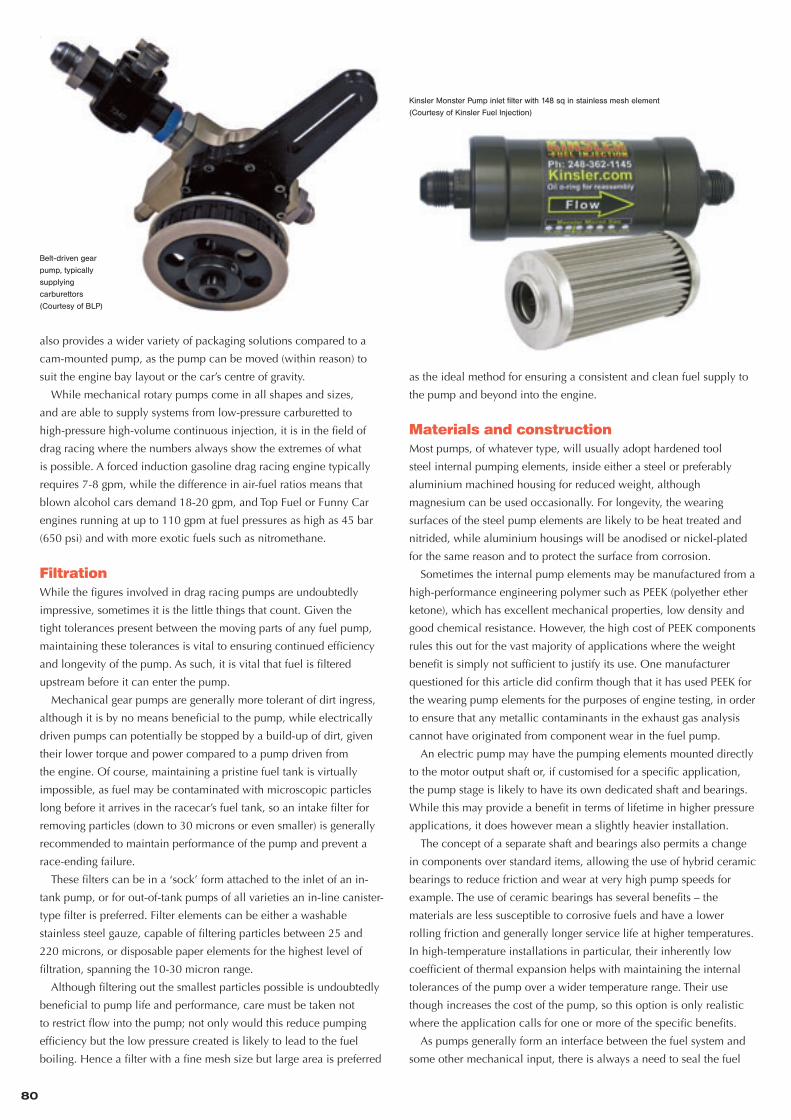
Belt-driven gear
pump, typically
supplying
carburettors
(Courtesy of BLP)
Kinsler Monster Pump inlet filter with 148 sq in stainless mesh element
(Courtesy of Kinsler Fuel Injection)
74-81 PUMPS (v.GR).indd 80 30/10/2012 20:25

81
FOCUS : FUEL PUMPS
cavity at the interface. For this there are two main choices of seal:
either a traditional O-ring type with retaining surfaces or a feather-
edge type seal. While feather-edge seals provide a lower friction
solution, an O-ring is a lower cost installation and service item.
Buna-N seal materials are generally used in the US for gasoline and
alcohol fuels, Viton for ethanol and EPDM (ethylene propylene diene
monomer) materials for nitromethane fuels. Graphite-impregnated
seals are a robust solution, easily able to cope with high shaft speeds
and fluid pressures, while being impervious to almost all fluids.
PTFE is often used in preference to Viton materials as it provides
a lower friction with a minimal stick-slip effect; it is also generally
harder wearing and has a greater range of chemical compatibility.
Elastomer/Viton-based materials are, however, better able to cope with
radial movement of the shaft and maintain a seal.
The compatibility of sealing materials with bio-fuels such as E85
bio-ethanol, which is highly corrosive, is a potential issue for the
use of these fuels not only in motorsport but the wider automotive
sector. While some pumps can claim to be compatible with E85 –
indeed, any pump will probably deliver any fluid – the problem is
more one of longevity. A typical EFI gasoline pump can be expected
to last up to 4000 h of running time without issue, but this may fall
to only 500 h when used with E85. Undoubtedly this will improve
with development; for the moment though, at least one supplier
recommends flushing the pump with standard gasoline between races.
The use of methanol fuel with magnesium casings is also
problematic, as when left static the fuel reacts and powders the surface
of the magnesium, so nearly all manufacturers opt for an aluminium
or steel solution to maintain compatibility. Methanol is also relatively
corrosive, with manufacturers suggesting cleansing with methylated
spirits at the end of each season and the use of pure silicone oil during
storage of the pump to preserve seal life.
ConclusionsRegardless of the level of competition, the provision of a reliable
and consistent fuel supply is essential. While the pumping methods
themselves are based on a few largely unchanged concepts, the
detailed implementation and attention to detail in perfecting the
design and manufacturing processes of these pumps is second to none,
with reliability as the watchword for all of the top manufacturers.
With the steadily increasing presence of alternative fuels such as
bio-ethanol, and the uptake of GDI systems, this is by no means an
industry standing still. The capability in terms of longevity, maximum
pressures and flow rates can only grow as these applications expand.
AcknowledgementsThe author would like to thank the following for their invaluable
insight and assistance with this article: Brad Cauzillo and James Kinsler
of Kinsler Fuel Injection, Martin Spickermann of SF Motorsporttechnik,
Annett Fischer of Bosch Engineering, Mike Laws and Carol Richardson
of BLP Racing Products, Goran Bogdanovic of Creative Performance
Racing, Jim Craig of Weldon Racing Pumps, Howard Stewart of Race
Pumps, Peter Huxley of Glencoe, Mike Kopchick Snr of Rage Fuel
Systems and Sid Waterman of Waterman Race Components.
SOME EXAMPLES OF FUEL PUMP MANUFACTURERS AND DISTRIBUTORS
GermanyBosch motorsport +49 7062 911 79101 www.bosch.com
SF motorsport Technology +49 6253 238652 www.sf-motorsporttechnik.de
UKGlencoe +44 (0) 1784 493555 www.fuelsystem.co.uk
Protec Fuel Systems +44 (0) 7850 172307 www.protecfuelpumps.com
USaaeromotive +1 913 647 7300 www.aeromotiveinc.com
aerospace Components +1 727 344 0091 www.aerospacecomponents.com
Baker engineering +1 616 837 8975 www.bakerengineeringinc.com
BLP Products +1 407 422 0394 www.blp.com
Bullet Proof Fuel Systems +1 336 476 9720 www.racepumps.com
C&S Specialities +1 636 723 4996 www.candsspecialties.com
Creative Performance racing +1 248 379 3565 www.cprracing.com
Dynapex +1 775 323 1822 www.dynapex.net
Fluid Control Products (Fuelab) +1 217 324 3737 www.fluidcontrol.net
Holley Performance Products +1 270 745 9547 www.holley.com
Jones racing Products +1 610 847 2028 www.jonesracingproducts.com
Kinsler Fuel Injection +1 248 362 1145 www.kinsler.com
KSe racing Products +1 615 672 5117 www.kse-racing.com
magnafuel Products +1 719 532 1897 www.magnafuel.com
motor Components, LLC +1 607 737 8011 www.facet-purolator.com
nitrous express +1 940 767 7694 www.nitrousexpress.com
Quick Fuel Technology +1 270 793 0900 www.quickfueltechnology.com
rage Fuel Systems +1 843 623 3500 www.ragefuelsystems.com
ron’s Fuel Injection Systems +1 800 513 3835 www.ronsfuel.com
Vortech engineering +1 805 247 0226 www.vortechsuperchargers.com
Waterman racing Components +1 707 884 4181 www.watermanracing.com
Weldon racing Pumps +1 440 232 2282 www.weldonracing.com
n
74-81 PUMPS (v.GR).indd 81 30/10/2012 20:25

For further information on High Power Media, any of our publications or online products please contact: Chris Perry, High Power Media Ltd, Whitfi eld House, Cheddar Road, Wedmore, Somerset, BS28 4EJ, England.
Tel: +44 (0)1934 713957 Fax: +44 (0)208 497 2102 E-mail: [email protected]
4 WAYS TO BUY:1) ONLINE AT WWW.HIGHPOWERMEDIA.COM
2) CALL US ON +44 (0)1934 713 957 DOWNLOAD A SUBS FORM FROM WWW.HIGHPOWERMEDIA.COM AND RETURN BY:
3) FAX TO +44 (0)208 497 2102
4) POST TO ADDRESS BELOW
Subscribe to the world’s leading technical magazine on racing engines and receive up to 30% off.
Sign up today to get the knowledge that is power atwww.highpowermedia.com
www.highpowermedia.com
THE COMMUNICATIONS HUB OF THE RACING POWERTRAIN WORLD
ISS
UE
064 race
en
gin
e TE
CH
NO
LOG
Y AU
GU
ST 2012
AUGUST 2012
New
F3 engines • RY
E Ford V
6 Twin Turbo D
ossier • British G
rand Prix Race R
eport • Cam
shafts Focus • Le Mans Prototypes R
ace Report • Transm
issions Focus
USA $25, UK £12.50, EUROPE e18
DAYTONA PROTOTYPE REVAMP
RYE’s radical Ford V6 turboLE MANS ENGINE SPECIALThe technology of 2012 and of 2014
BRAIN OF THE TRAINIn-depth focus on camshafts
DELTAWING’S BEN BOWLBY:
Proving a point at Le Mans
www.highpowermedia.com01 064COVER.indd 1
25/07/2012 12:17
THE COMMUNICATIONS HUB OF THE RACING POWERTRAIN WORLD
ISS
UE
065 race
en
gin
e TE
CH
NO
LOG
Y SE
PT/O
CT 2012
SEPTEMBER/OCTOBER 2012
Nissan LM
P2 V
8 Dossier • R
ace Engine of the Year N
ominations • C
rankshafts Focus • Green G
T H2 • U
S N
ationals Rep
ort • Sub
aru GR
C E
ngine Rep
ort • Powertrain S
ensors Focus
USA $25, UK £12.50, EUROPE e18
NISSAN’S FLAWLESS LM P2 V8Exploring the production engine pacesetter
VITAL CONNECTIONSFocus on crankshafts
US NATIONALSThe ultimate engine war
JEAN-FRANCOIS WEBER: Taking Le Mans into a greener future
www.highpowermedia.com
01 065COVER.indd 1
20/09/2012 13:28
THE COMMUNICATIONS HUB OF THE RACING POWERTRAIN WORLD
ISS
UE
066 race
en
gin
e TE
CH
NO
LOG
Y NO
VE
MB
ER
2012
NOVEMBER 2012
Mountune/O
MS
E R
allycross Ford Turbo Dossier • D
elft Formula S
tudent • Advanced M
etals Focus • Bloodhound rocket test • Le M
ans/Petit Le Mans R
eport • Fuel Pumps Focus
USA $25, UK £12.50, EUROPE e18
LITTLE FORD, HUGE PUNCH
Mountune’s 50+ bar bmep Rallycross Duratec
MATERIALS
FROM SPACE
Focus on
advanced metals
IT IS
INDEED
ROCKET
SCIENCE!
Bloodhound
tests the ultimate
race motor
ROB WHITE:
Renault’s Grand Prix winning ways
www.highpowermedia.com
01 066COVER.indd 1
30/10/2012 13:19
SUBSCRIBETODAY
SIGN-UP TO
OUR FREE TECHNICAL
E-NEWSLETTERS AT
WW
W.RET-MONITOR.COM
& WW
W.F1-MONITOR.COM
This report explains all aspects of the performance of top motorcycle machines. We look in depth at the MotoGP machines as well as the Superbike racers used in the World Superbike and AMA Championships. We identify as never before the keys to success in these exciting forms of racing.
race e
ngin
e TE
CH
NO
LOG
Y SP
EC
IAL R
EP
OR
T M
OTO
RC
YC
LE R
AC
E T
EC
HN
OLO
GY
20
09
A special report
USA $50, UK £20, EUROPE e35
DUCATI – WHAT IS DIFFERENT ABOUT THE DESMOSEDICI?
BMW AND APRILIAThe Superbike new boys
HYDREX HONDATop privateer team in BSB
MOTORCYCLE race
00_MRT09_Cover2.indd 1 19/11/09 11:27:54
v12009
BUYTODAY
They still use Truck arm suspension and rev counter dials but some of the best engineers in all of racing are employed by today’s teams and for them the archaic elements of the car are a great challenge. Blending today and yesterday’s technology provides a fascinating engineering puzzle.
race
en
gin
e TE
CH
NO
LOG
Y SP
EC
IAL R
EPO
RT
CU
P R
AC
E T
EC
HN
OLO
GY
2012
A special report
USA $50, UK £20, EUROPE e35
DRIVER ENGINEERINGFinding the elusive winning edge
TECHNOLOGY FOCUSNASCAR brakes and chassis uncovered
IN THE DRAFTSuperspeedway engineering investigated
01 CRTv3 3.indd 1 20/02/2012 13:20
v3 2012
EVERY MARCH
This report puts the powertrain into the whole car context. Featuring input from many top Formula One technical directors and written by Ian Bamsey, each report is a unique review of the engineering and mechanics of contemporary Grand Prix racing cars, including a preview of future trends.
F1 racerace
en
gin
e TE
CH
NO
LOG
Y SP
EC
IAL R
EPO
RT
F1
RA
CE
TE
CH
NO
LOG
Y 2
012/2
013
A special report
USA $50, UK £20, EUROPE e35
OFF-TRACK TESTING SECRETS
AERO-ELASTICITY IN FORMULA ONE
NEW LOTUS: ENSTONE’S CHARGE BACK TO THE FRONT
PLUSClutch tech to win
The Grand Prix paddockSuspension state of the art
F1 race
01_F1RT6 COVER 1.indd 1 27/04/2012 11:41
v6 2012
EVERY MAY
This technical report looks in depth at the cars that compete in the 24 Hour race at Le Mans. Published every July by High Power Media under offi cial licence with the ACO, this report shows you the amazing engineering and technology required to race non-stop twice around the clock.
24 HOUR race
RA
CE
EN
GIN
E TE
CH
NO
LOG
Y SP
EC
IAL R
EPO
RT
24
HO
UR
RA
CE
TE
CH
NO
LOG
Y 2
012
A SPECIAL REPORT
USA $50, UK £20, EUROPE E35
RACING THE CLOCKThe challenge of competing at Le Mans
TECHNOLOGY FOCUSLMP manufacturing and electronics investigated
Under offi cial licence with the ACO
NEXT GENERATIONToyota Hybrid uncovered
01_24HRT12 v3.indd 1 03/07/2012 21:03
v62012
EVERY JULY
Engineering a Top Fuel car that exploits 8000 bhp for just a few vital seconds is one of the toughest challenges in racing. This report explores in depth the engineering of all forms of professional drag racing, providing a fascinating insight into a surprisingly complex technological endeavour.
race
en
gin
e TE
CH
NO
LOG
Y SP
EC
IAL R
EPO
RT
DR
AG
RA
CE
TE
CH
NO
LOG
Y 2
012
A special report
USA $40, UK £20, EUROPE e30
SWISS TIMEEurope’s fastest dragster profi led
TECHNICAL FOCUSTorque converters and engine systems investigated
WATERBORNE BULLETThe world of Top Fuel Hydroplanes
01 DRT2012 A.indd 1 06/09/2012 12:07
v3 2012
EVERY SEPTEMBER
Rally cars compete on everyday road tarmac, gravel, dirt, even ice and snow so the rally car has to be very versatile. It’s a 300 bhp missile that accelerates from 0-100 kph in under 3 seconds. The design and development of these cars has never been more deeply analysed.
race
en
gin
e TE
CH
NO
LOG
Y SP
EC
IAL R
EPO
RT
WO
RLD
RA
LLY R
AC
E T
EC
HN
OLO
GY
2012
A special report
USA $50, UK £20, EUROPE e35
NEW RALLY GENERATIONInside the latest World Rally Cars
WINNING MONTE CARLORally Car development
SIDEWAYS TO VICTORY Rallying’s extreme engineering
01_RRTV1_cover.indd 1 04/09/2012 22:56
v1 2012
PRE-ORDERTODAY
COMING IN DECEMBER
RETAD_OCT12_A4.indd 1 30/10/2012 15:14


