Study on the Durability of Surface Coating Materials for Concrete Structures
Iwao SASAKI1, Itaru NISHIZAKI2
Abstract
Surface coating is one of the major approaches to repair deteriorated concrete. There are various coating materials and application methods for concrete surface repair and strengthening, but selection criterion for these materials has not been established yet. In order to establish optimum coating selection procedures, reliable durability estimation is definitely indispensable for LCC analyses. It is important that how we can extend service life for each coating system depend on the damage level and corrosion environment, although test method for durability evaluation itself might not be finalized.
To reveal the durability and applicable conditions of surface coating systems, maritime exposure tests using controlled concrete specimens have been conducted. Furthermore, a lot of deteriorated bridges were repaired already, and these bridges suggest many informative in-situ results to verify the durability of coating systems. This paper states the summery of the durability investigations of concrete surface coating materials. 1. Introduction
Various coating materials and application methods for concrete surface repair and strengthening have been developed. However, selection criterion for these materials has not been established yet at the current moment. Selecting procedures of concrete coating materials must focus on deteriorating mechanisms diagnosed carefully by the conditions of target structures.
For instance, in case of salt damage, repair policy should consider corrosion environment and deteriorating condition to determine symptomatic indications such as, 1) removal of permeated chloride ions, 2) penetration block of chloride ions, moisture, and oxygen, 3) de-rusting of rebar, 4) corrosion-control method (coating or potential control). However, it is not still ambiguous to determine which is the best material and coating system, because there is not enough durability data to estimate.
In order to establish optimum coating system selection procedures, at least for all typical coating materials, reliable durability estimation is definitely indispensable for LCC analyses. Although durability evaluation method itself might not be finalized, it is important that how we can extend the service life for each coating system depend on the
1 Senior Researcher, Advanced Materials Research Team, Materials and Geotechnical Engineering Research Group, Public Works Research Institute, (1-6 Minamihara, Tsukuba City, 305-8516) 2 Team Leader, Advanced Materials Research Team, Materials and Geotechnical Engineering Research Group, Public Works Research Institute, (1-6 Minamihara, Tsukuba City, 305-8516)
damage level and corrosion environment of a target structure. There are a lot of repair methods for concrete structures. The authors have been
studying to reveal the issue of durability of coating system against salt damage of bridges. 2. Surface Coating Material Specifications and Evaluation Methodology
Surface coating is one of the effective countermeasures applicable to damaged concrete structures. It has been applied to repair work such as salt damage for a long time. Especially, it was adopted as a major approach in 1980s with the increase of deteriorated concrete structures.
In 1984, the guideline “Countermeasures against Salt Damages to Concrete Bridges (Draft)” 1) was tentatively introduced. Subsequently, a lot of bridge structures have been repaired by surface coating following the guideline. Table 1 shows approaches and typical repair method for salt damage. Table 2 shows the classification of coating materials specified in the guideline.
Table 1 Repair Policy and Examples of Measures for Salt Damaged Structures
Expecting effect Examples of measures
Reduction of the supply of causative agent to steel corrosion Surface coating
Removal of causative agent to steel corrosion Patch repair, Desalination
Inhibition of corrosion reaction of steel Surface coating, Electric protection, Patch repair,
Enhancement of load bearing capacity FRP laminate, Patch repair, Out-cable, Lining
Table 2 Classifications of Surface Coating Materials
Category Type and conditions of concrete members Characteristic requirement on the specification
A for Pre-stressed Concrete (PC) ---
B mainly for Reinforced Concrete (RC) Crack following capability
C Specific structure part
such as difficult to re-paint or severe corrosion estimated (Long-life)
Chloride barrier properties
As for the major approach of the guideline, i.e. covering concrete depth control, has been revised through intensive investigations and discussions2,3,4,5). The revised concept was documented in The Specifications for Highway Bridges2). The specification categorizes “S” classification additionally for extremely severe corrosion environment and location. Surface coating of concrete is considered as an approach for the so-called super salt damage countermeasure.
On the other hand, specifications and usage of surface coating has not been studied enough. The recommendation by JSCE6) is informative, but the guideline (for coating) still remains tentative and has not been well proven in terms of the spec. Furthermore, during these 20years, material and layer system may has been developed so far. The defining properties, test conditions, and specified values have to be examined whether the specification can evaluate the durability of coating materials.
In order to confirm the specification, maritime exposure tests using controlled
concrete specimens have been conducting by Public Works Research Institute and Pre-stressed Concrete Association since 1980s. At the same time, a lot of deteriorated bridges were repaired referring the guideline. These bridges suggest many informative in-situ results to verify the durability of coating systems. This paper states the summery of durability investigations.
Table 3 Performance Requirement and Evaluation Methodologies of Surface Coating Materials
Performance Requirement Evaluation Item Specification in Guideline1)
Flat and smoothness Appearance visual check Qualitative
Weathering resistance Visual check after weathering Qualitative
Adhesive property Adhesion strength to concrete Quantitative
Crack following ability Zero-span elongation Quantitative
Chloride barrier property Cl- transmission rate Quantitative
Water impermeability Water transmission rate (Quantitative)
Vapor impermeability Vapor transmission rate ---
Oxygen barrier property O2 transmission rate ---

3. Exposure Tests by Controlled Specimens
Many durability data can be derived from exposure tests because controlled specimens and corrosion environment can be used. Public Works Research Institute and Pre-stressed Concrete Association have been conducting exposure tests of concrete surface coating since 1980s in a joint research program.
Specimens in the exposure tests are coated concrete beams with the square section of 200mm and the length of 1,200mm. Covering depth of rebars was 25mm. Various coating materials shown in Table 4 were applied on the surface of RC or PC beams depending upon each coating material category. Exposure site shown in Photo 1 is located in Shizuoka, Japan
Follow-up investigations were conducted after 20years exposure in splash-zone of the exposure site. Damage rate of surface coat was evaluated as the equation (1) by visual inspection, and adhesion strength and chloride ion content distribution were measured through coring investigations. 100(%) ×=
areacoatedEntireareaDamagedratioDamage (1)
Table 4 Surface Coated Concrete Specimens for Exposure Test
Coating system Primer Putty Intermediate coat Top coat Spec.
A.cat: Epoxy Epoxy Epoxy Epoxy PolyUrethane
On-spec system of the guideline
“Countermeasures against Salt Damages to
Concrete Bridges”
B.cat: Flexible Epoxy Epoxy Epoxy Flexible Epoxy Flexible PolyUrethane
B.cat: Flexible PolyUrethane Epoxy Epoxy Flexible PolyUrethane
Flexible PolyUrethane
C.cat: High-build Epoxy Epoxy Epoxy High-build Epoxy PolyUrethane
C.cat: VinylEster Epoxy Epoxy High-build VinylEster PolyUrethane
Super High-build Epoxy Epoxy Epoxy Super High-build Epoxy PolyUrethane
New system at the period the guideline
“Countermeasures against Salt Damages to
Concrete Bridges” published
Super High-build PolyUrethane
Poly Urethane Epoxy
Super High-build PolyUrethane
2plyPolyUrethane
Modified Epoxy Epoxy Epoxy Mod.Epoxy 2ply PolyUrethane Cement-type ---
Urethane ---Silicone Rubber ---Acrylic Rubber ---Inorganic coat Inorganic Epoxy Cement-type Inorganic
PolymerCement PolymerCement PolyUrethane
Photo 1 Exposure Site
Deck #3
Adhesion test was done by a pull-off testing, and chloride ion content was
measured by potentiometric titration following JSCE- G573-2003. Results of Exposure Tests
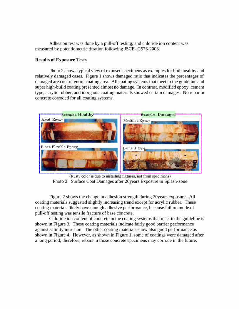
Photo 2 shows typical view of exposed specimens as examples for both healthy and relatively damaged cases. Figure 1 shows damaged ratio that indicates the percentages of damaged area out of entire coating area. All coating systems that meet to the guideline and super high-build coating presented almost no damage. In contrast, modified epoxy, cement type, acrylic rubber, and inorganic coating materials showed certain damages. No rebar in concrete corroded for all coating systems.
Figure 2 shows the change in adhesion strength during 20years exposure. All coating materials suggested slightly increasing trend except for acrylic rubber. These coating materials likely have enough adhesive performance, because failure mode of pull-off testing was tensile fracture of base concrete.
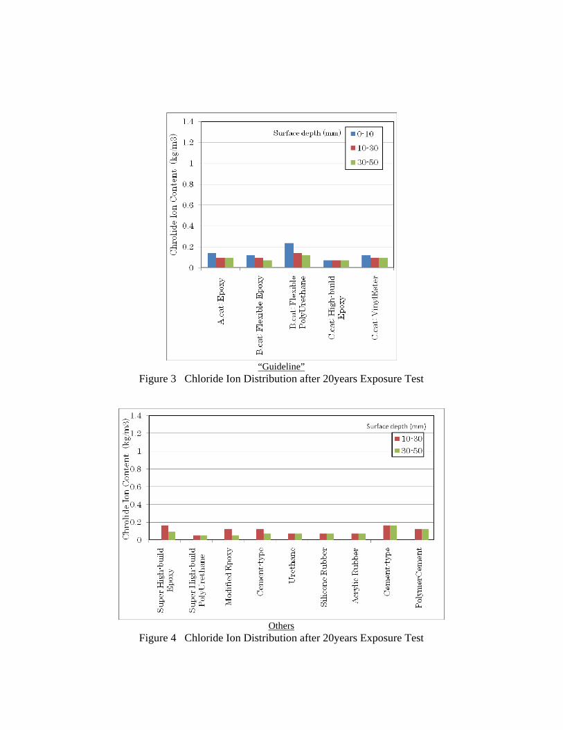
Chloride ion content of concrete in the coating systems that meet to the guideline is shown in Figure 3. These coating materials indicate fairly good barrier performance against salinity intrusion. The other coating materials show also good performance as shown in Figure 4. However, as shown in Figure 1, some of coatings were damaged after a long period; therefore, rebars in those concrete specimens may corrode in the future.
(Rusty color is due to installing fixtures, not from specimens) Photo 2 Surface Coat Damages after 20years Exposure in Splash-zone

In contrast, specimens without coating showed quite high chloride ion content. In
any cases, more than 10kg/m3 in the near surface part as shown in Figure 5 and 6. Chloride permeation depth is different; the larger W/C, the deeper chloride permeation. The amount of chloride ion can be quite high around rebars.
These results prove that the coating systems that meet to the guideline have good durability and barrier performance against chloride attack.
“Guideline” Others
Figure 2 Change in the Adhesion Strength of Coating during Exposure Test
A.cat: Epoxy
B.cat: Flexible EpoxyB.cat: Flexible PolyUrethane
C.cat: High-build EpoxyC.cat: VinylEster
Super High-build EpoxySuper High-build
Modified EpoxyCement-type
UrethaneSilicone Rubber
Acrylic RubberCement-type
PolymerCement
Figure 1 Damage Ratio of Surface Coat Damage ratio (%)
Gui
dlin
e O
ters
“Guideline”
Figure 3 Chloride Ion Distribution after 20years Exposure Test
Others
Figure 4 Chloride Ion Distribution after 20years Exposure Test

Figure 5 Chloride Ion Distribution after 20years Exposure Test
Without surface coating
Surface Depth (cm)
Chl
orid
e Io
n C
onte
nt (
kg/m
3)
Figure 6 Chloride Ion Distribution after 20years Exposure Test
Without surface coating
Surface Depth (cm)
Chl
orid
e Io
n C
onte
nt (
kg/m
3)
4. Durability Verification by Actual Concrete Bridges
As for countermeasures against salt damages of concrete structures particularly for severe corrosion environment where even covering depth may not be effective, surface coating has been applied sometimes for many years. However, quantitative investigations focusing on coating materials properties are not enough still now. Therefore, the authors carried out evaluations of coating material testing to verify the reliability of guidelines.
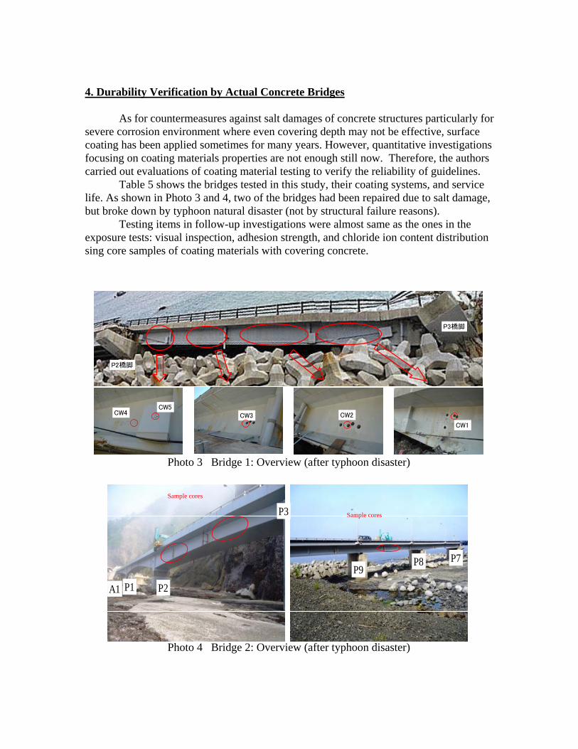
Table 5 shows the bridges tested in this study, their coating systems, and service life. As shown in Photo 3 and 4, two of the bridges had been repaired due to salt damage, but broke down by typhoon natural disaster (not by structural failure reasons).
Testing items in follow-up investigations were almost same as the ones in the exposure tests: visual inspection, adhesion strength, and chloride ion content distribution sing core samples of coating materials with covering concrete.
CW4CW5
CW3 CW2
CW1
P2橋脚
P3橋脚
Photo 3 Bridge 1: Overview (after typhoon disaster)
Photo 4 Bridge 2: Overview (after typhoon disaster)
P1 P2
P3
P9P8 P7
A1
Sample cores
Sample cores
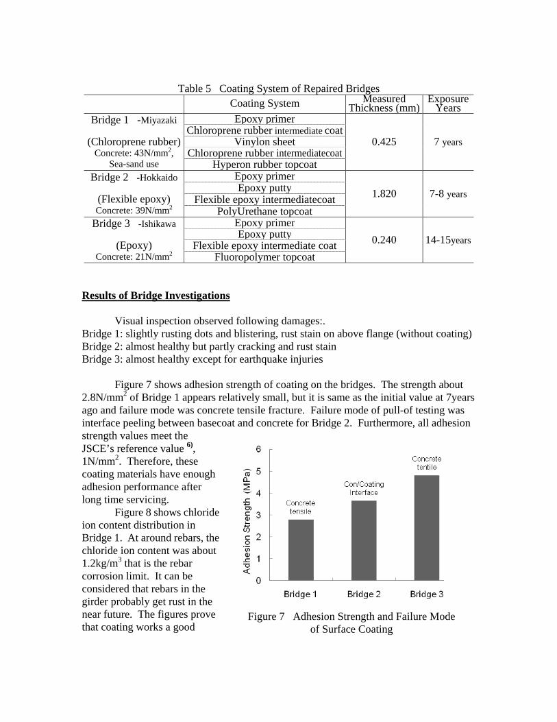
Table 5 Coating System of Repaired Bridges Coating System Measured
Thickness (mm) Exposure
YearsBridge 1 -Miyazaki
(Chloroprene rubber)
Concrete: 43N/mm2, Sea-sand use
Epoxy primer
0.425 7 years Chloroprene rubber intermediate coat
Vinylon sheetChloroprene rubber intermediatecoat
Hyperon rubber topcoatBridge 2 -Hokkaido
(Flexible epoxy) Concrete: 39N/mm2
Epoxy primer1.820 7-8 yearsEpoxy putty
Flexible epoxy intermediatecoatPolyUrethane topcoat
Bridge 3 -Ishikawa
(Epoxy) Concrete: 21N/mm2
Epoxy primer0.240 14-15yearsEpoxy putty
Flexible epoxy intermediate coatFluoropolymer topcoat
Results of Bridge Investigations
Visual inspection observed following damages:. Bridge 1: slightly rusting dots and blistering, rust stain on above flange (without coating) Bridge 2: almost healthy but partly cracking and rust stain Bridge 3: almost healthy except for earthquake injuries
Figure 7 shows adhesion strength of coating on the bridges. The strength about
2.8N/mm2 of Bridge 1 appears relatively small, but it is same as the initial value at 7years ago and failure mode was concrete tensile fracture. Failure mode of pull-of testing was interface peeling between basecoat and concrete for Bridge 2. Furthermore, all adhesion strength values meet the JSCE’s reference value 6), 1N/mm2. Therefore, these coating materials have enough adhesion performance after long time servicing.
Figure 8 shows chloride ion content distribution in Bridge 1. At around rebars, the chloride ion content was about 1.2kg/m3 that is the rebar corrosion limit. It can be considered that rebars in the girder probably get rust in the near future. The figures prove that coating works a good
Figure 7 Adhesion Strength and Failure Mode
of Surface Coating
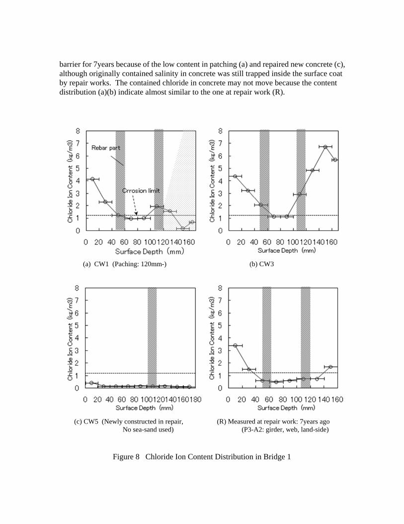
barrier for 7years because of the low content in patching (a) and repaired new concrete (c), although originally contained salinity in concrete was still trapped inside the surface coat by repair works. The contained chloride in concrete may not move because the content distribution (a)(b) indicate almost similar to the one at repair work (R).
(a) CW1 (Paching: 120mm-) (b) CW3
(c) CW5 (Newly constructed in repair, (R) Measured at repair work: 7years ago No sea-sand used) (P3-A2: girder, web, land-side)
Figure 8 Chloride Ion Content Distribution in Bridge 1

5. Conclusions
Surface coating that meet the specification of the guideline (1984) indicates fairly good performance even after long time exposure or service. This suggests that the specification of the guideline may be empirically proved the validity.
In the case repair of deteriorated and salt containing concrete, the containment effect of surface coating should be carefully examined.
It should be clarified the limit of application of the concept covering concrete depth countermeasure quantitatively as much as possible. In the same manner, the scope of application of surface coating should be stated as well. LCC analyses may give appropriate allocation of roles including the other countermeasures such as chloride removal and cathodic protection of rebars. Acknowledgments
The authors gratefully thank the related regional offices of MLIT and prefecture for providing valuable specimens and data, and the management of the exposure facility as well. References
1) Japan Road Association : Countermeasures against Salt Damages to Concrete Bridges
(Draft), 1984.2 2) Japan Road Association : The Specifications for Highway Bridges, 2002.3 3) Kawano H.: Life Cycle Cost of Prestressed Concrete Bridges - Examples in Severe
Chloride Environments, Proceedings of 18th US-Japan Bridge Engineering Workshop, 2002.10
4) Nakatani S., Tamakoshi A., Hiromatsu A.: Examination about Countermeasures against Salt Damages to Concrete Bridges - The Revision of the Specifications of Highway Bridges, Proceedings of 18th US-Japan Bridge Engineering Workshop, 2002.10
5) National Institute for Land and Infrastructure Management : Countermeasures of Salt Damage for Concrete Bridge, TECHNICAL NOTE of NILIM No.55, 2002.11
6) JSCE : Recommendation for Concrete Repair and Surface Protection of Concrete Structures, Concrete Library 119, 2005.4


