Download - Steel Designing Project

8/13/2019 Steel Designing Project
http://slidepdf.com/reader/full/steel-designing-project 1/84
[Year]
S MAITRA
[Company name]
[Date]
[Document title]

8/13/2019 Steel Designing Project
http://slidepdf.com/reader/full/steel-designing-project 2/84
1
We are supposed to design an Industrial truss in this particular project. It
would be of a specified kind. Here are some given data according to which I am supposeddesign the particular truss. They are given below →
General data:
Height of the truss = (3.6+.2y) m [where y = my position in the group]
Length of the truss = (15+N) m [where N = my group no]
Hence my general data is
Height of the truss = (3.6+.2×2) m = 4 m
Length of the truss = (15+6) m = 21 m
STEEL DESIGNING PROJECT
•
TEACHER - B.K.R SIR• STUDENT - SUBHAJIT MAITRA

8/13/2019 Steel Designing Project
http://slidepdf.com/reader/full/steel-designing-project 3/84
2
From the assumption of the angle shown in the fig. we have,
( )
( )=
Now,
From we have,
()
[Where, L=AF] …………. (1)
Again,
From we have,
()
[Where, L=AF] …………. (2)
Here, AB =√
= 5.62.
Now,
()()
()()
()
()
() () () ()
()
()
()
()
CALCULATION OF ANGLE:-

8/13/2019 Steel Designing Project
http://slidepdf.com/reader/full/steel-designing-project 4/84
3
We have,
()
Dead Load due to concr ete asbestos sheeting: -Unit load=.13KN
Effective area of point B, C, D, E, F, G, H
=2.81×3× cos(20.85°)=7.88 m2
Effective area of point E
=7.88 m2
Effective area of point A, I
=1.71×3× cos(20.85°)=4.8 m2
Hence,
Dead load due to sheeting →
@ Point B, C, D, E, F, G, H = 7.88×.13=1.03KN
@ Point B, C, D, E, F, G, H = 7.88×.13=1.03KN
@ Point B, C, D, E, F, G, H = 4.8×.13=.624KN
Dead Load due to purl in: -We are using MC-100
Unit load=.098KN
Hence,
Dead load due to purlin →
@ All points except E = .098×3=.294KN
@ Point E= .294×2=.588KN
Dead Load due to pur li n: -Total length of tie=21m
DEAD LOAD CALCULATION
8/13/2019 Steel Designing Project
http://slidepdf.com/reader/full/steel-designing-project 5/84
4
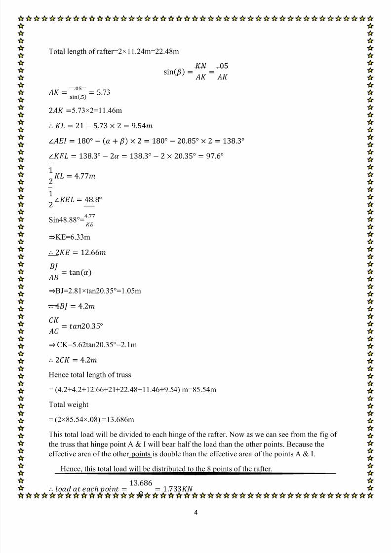
Total length of rafter=2×11.24m=22.48m
()
() 73
5.73×2=11.46m
( )
Sin48.88°=
KE=6.33m
()
BJ=2.81×tan20.35°=1.05m
CK=5.62tan20.35°=2.1m
Hence total length of truss
= (4.2+4.2+12.66+21+22.48+11.46+9.54) m=85.54m
Total weight
= (2×85.54×.08) =13.686m
This total load will be divided to each hinge of the rafter. Now as we can see from the fig of
the truss that hinge point A & I will bear half the load than the other points. Because the
effective area of the other points is double than the effective area of the points A & I.
Hence, this total load will be distributed to the 8 points of the rafter.
8/13/2019 Steel Designing Project
http://slidepdf.com/reader/full/steel-designing-project 6/84
5
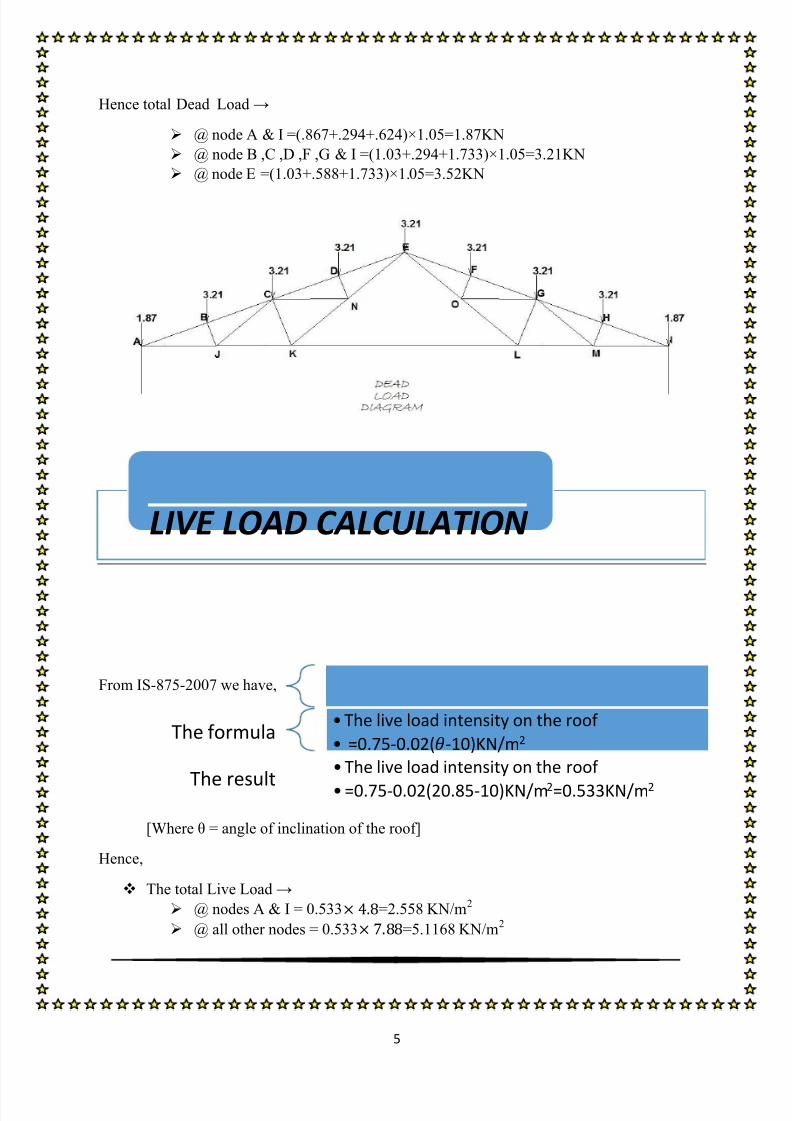
Hence total Dead Load →
@ node A & I =(.867+.294+.624)×1.05=1.87KN
@ node B ,C ,D ,F ,G & I =(1.03+.294+1.733)×1.05=3.21KN
@ node E =(1.03+.588+1.733)×1.05=3.52KN
From IS-875-2007 we have,
[Where θ = angle of inclination of the roof]
Hence,
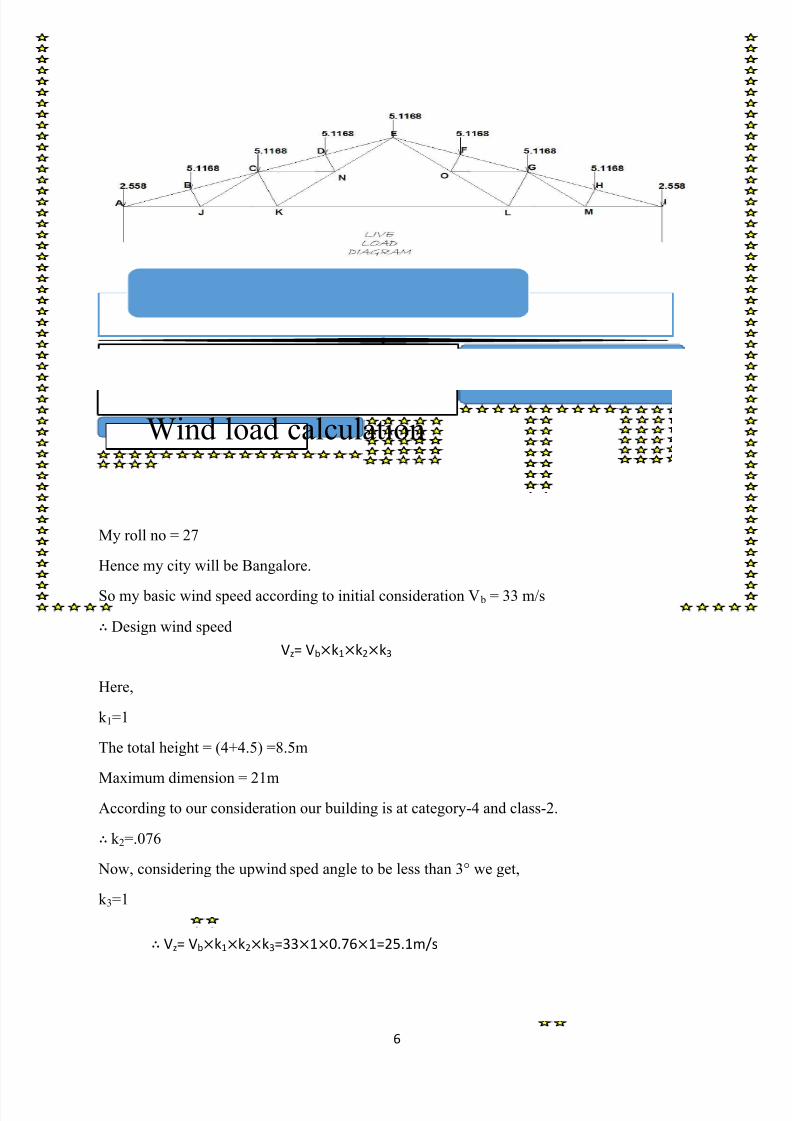
The total Live Load →
@ nodes A & I = 0.533 =2.558 KN/m2
@ all other nodes = 0.533 =5.1168 KN/m2
LIVE LOAD CALCULATION
The formula• The live load intensity on the roof
• =0.75-0.02(-10)KN/m2
The result
• The live load intensity on the roof
• =0.75-0.02(20.85-10)KN/m2=0.533KN/m2
8/13/2019 Steel Designing Project
http://slidepdf.com/reader/full/steel-designing-project 7/84
6
My roll no = 27
Hence my city will be Bangalore.
So my basic wind speed according to initial consideration V b = 33 m/s
Design wind speed
Here,
k 1=1
The total height = (4+4.5) =8.5m
Maximum dimension = 21mAccording to our consideration our building is at category-4 and class-2.
k 2=.076
Now, considering the upwind sped angle to be less than 3° we get,
k 3=1
Wind load calculation
Vz= Vbk1k2k3
Vz= Vbk1k2k3=3310.761=25.1m/s
8/13/2019 Steel Designing Project
http://slidepdf.com/reader/full/steel-designing-project 8/84
7
As our opening is less than less than 5%(<5%)
We will take C pi=0.2
Now,
w=21 m
h=4.5m
Hence,
WIND ANGLE
=0°
WIND ANGLE
=90°
EF GH EG FH
20° -0.4 -0.4 -0.7 -0.6
30° 0 -0.4 -0.7 -0.6
20.85° -0.366 -0.4 -0.7 -0.6
C pi=0.2 WIND ANGLE
=0°
WIND ANGLE
=90°
C pe - C pi
EF GH EG FH
-0.2-0.366
=-0.566
-0.2-0.4
=-0.6
-0.7-0.2
=-0.9
--0.6-0.2
=-0.8
C pi=-0.2 WIND ANGLE
=0°
WIND ANGLE
=90°
C pe - C pi
EF GH EG FH
0.2-0.366
=-0.166
0.2-0.4
=-0.2
-0.7+0.2
=-0.5
--0.6+0.2
=-0.4
Now, from the IS-875-1984 we have,
Wind load F= (C pe - C pi)Apa

8/13/2019 Steel Designing Project
http://slidepdf.com/reader/full/steel-designing-project 9/84
8
FOR WIND ANGLE θ=0°
Point Influence
Area (m2
)
Wind angle,
Θ=0°
pa Fz
C pi=0.2 C pi=
-0.2
0.387 C pi=0.2 C pi=
-0.2
A 4.8 -0.566 -0.166 0.387 -1.03 -0.3
B 7.88 -0.566 -0.166 0.387 -1.68 -0.5
C 7.88 -0.566 -0.166 0.387 -1.68 -0.5
D 7.88 -0.566 -0.166 0.387 -1.68 -0.5
E 3.94 -0.566 -0.166 0.387 -0.84 -0.25
E 3.94 -0.6 -0.2 0.387 -0.9 -0.3
F 7.88 -0.6 -0.2 0.387 -1.79 -0.6
G 7.88 -0.6 -0.2 0.387 -1.79 -0.6
H 7.88 -0.6 -0.2 0.387 -1.79 -0.6
I 4.8 -0.6 -0.2 0.387 -1.1 -0.36
FOR WIND ANGLE θ=90°
FOR EG
Point Influence
Area (m2)
Wind angle,
Θ=0°
pa Fz
C pi=0.2 C pi=
-0.2
0.387 C pi=0.2 C pi=
-0.2
A 4.8 -0.9 -0.5 0.387 -1.63 -0.91

8/13/2019 Steel Designing Project
http://slidepdf.com/reader/full/steel-designing-project 10/84
9
B 7.88 -0.9 -0.5 0.387 -2.68 -1.5
C 7.88 -0.9 -0.5 0.387 -2.68 -1.5
D 7.88 -0.9 -0.5 0.387 -2.68 -1.5
E 3.94 -0.9 -0.5 0.387 -1.38 -0.75
E 3.94 -0.9 -0.5 0.387 -1.38 -0.75
F 7.88 -0.9 -0.5 0.387 -2.68 -1.5
G 7.88 -0.9 -0.5 0.387 -2.68 -1.5
H 7.88 -0.9 -0.5 0.387 -2.68 -1.5
I 4.8 -0.9 -0.5 0.387 -1.63 -0.91
FOR WIND ANGLE θ=90°
FOR FH
Point Influence
Area (m2)
Wind angle,
Θ=0°
pa Fz
C pi=0.2 C pi=
-0.2
0.387 C pi=0.2 C pi=
-0.2
A 4.8 -0.8 -0.4 0.387 -1.45 -0.72
B 7.88 -0.8 -0.4 0.387 -2.38 -1.19
C 7.88 -0.8 -0.4 0.387 -2.38 -1.19
D 7.88 -0.8 -0.4 0.387 -2.38 -1.19
E 3.94 -0.8 -0.4 0.387 -1.29 -0.6
E 3.94 -0.8 -0.4 0.387 -1.29 -0.6
F 7.88 -0.8 -0.4 0.387 -2.38 -1.19
G 7.88 -0.8 -0.4 0.387 -2.38 -1.19
H 7.88 -0.8 -0.4 0.387 -2.38 -1.19
I 4.8 -0.8 -0.4 0.387 -1.45 -0.72

8/13/2019 Steel Designing Project
http://slidepdf.com/reader/full/steel-designing-project 11/84
10

8/13/2019 Steel Designing Project
http://slidepdf.com/reader/full/steel-designing-project 12/84
11
8/13/2019 Steel Designing Project
http://slidepdf.com/reader/full/steel-designing-project 13/84
12
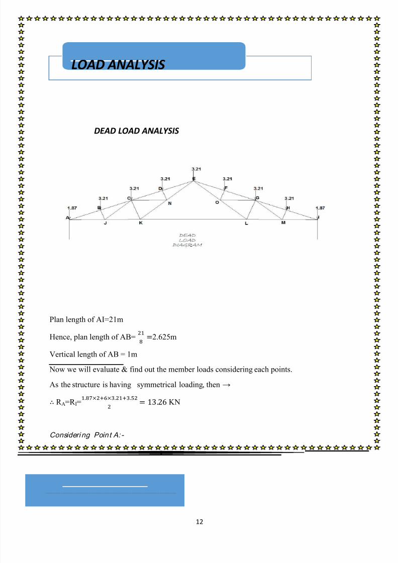
DEAD LOAD ANALYSIS
Plan length of AI=21m
Hence, plan length of AB=
2.625m
Vertical length of AB = 1m
Now we will evaluate & find out the member loads considering each points.
As the structure is having symmetrical loading, then →
R A=R I=
KN
Consideri ng Poin t A: -
V=0,
FAB FAJ=-R A+1.87
LOAD ANALYSIS

8/13/2019 Steel Designing Project
http://slidepdf.com/reader/full/steel-designing-project 14/84
13
FAB FAJ= -11.39
H=0,
FAB+ FAJ= 0
FAB FAJ= 0
FAB=-32.745KN
FAJ=30.647KN
Consideri ng Poin t B: -
V=0,
FBC FBJ= FAB
FBC FBJ= 8.445
H=0,

8/13/2019 Steel Designing Project
http://slidepdf.com/reader/full/steel-designing-project 15/84
14
FBC + FBJ = FAB
FBC + FBJ= 30.616
FBC=31.6KN
FBJ=3 KN
Consideri ng Poin t J:-
V=0,
FJC FJK = FJA FJB
FJC FJK =
H=0,
FJC+ FJK = FJB FJB
FJC+ FJK =
FJC=4.318KN
FJK =26.328 KN
Taking a section 11’
M=0,
FKL ( )
FKL=17.47KN
Consideri ng Poin t K: -
V=0,

8/13/2019 Steel Designing Project
http://slidepdf.com/reader/full/steel-designing-project 16/84
15
FKN FKC = FJK
FKN FKC =
H=0,
FKN + FKC= FJK FKL
FKN + FKC=
FKN=10.26KN
FKC=8.91 KN
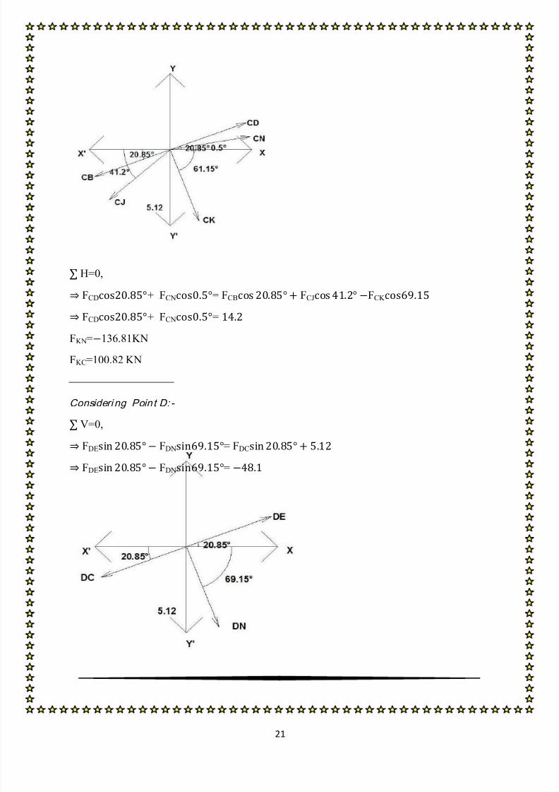
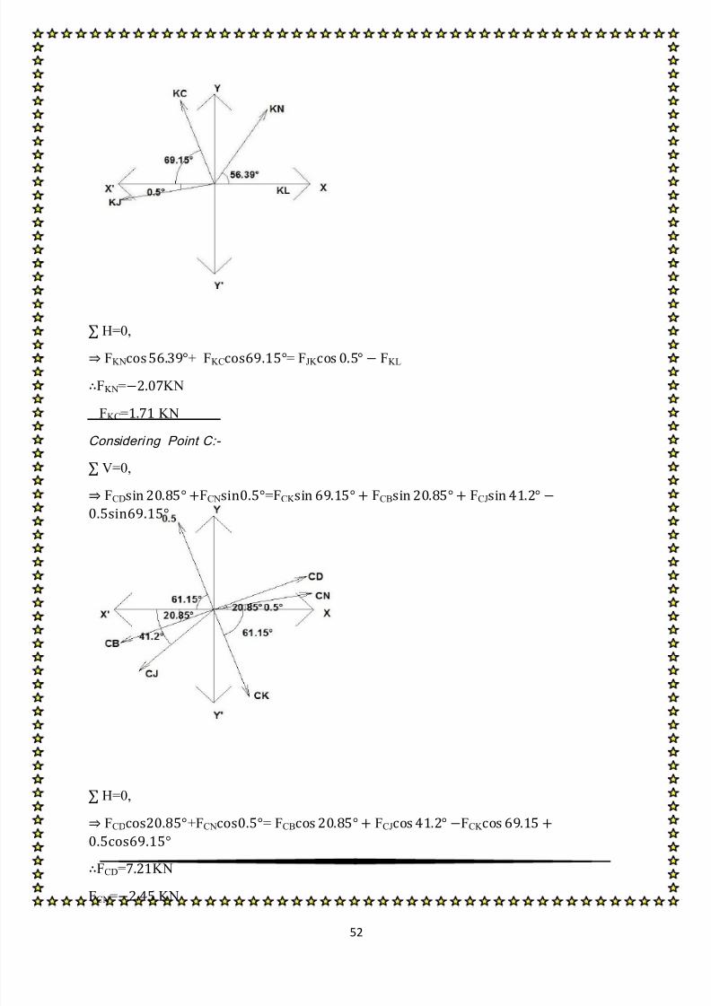
Considering Point C:-
V=0,
FCD FCN= FCK FCB FCJ
FCD FCN=
H=0,

8/13/2019 Steel Designing Project
http://slidepdf.com/reader/full/steel-designing-project 17/84
16
FCD+ FCN= FCB FCJ FCK
FCD+ FCN=
FKN=38.32KN
FKC=12.713 KN
Consideri ng Poin t D: -
V=0,
FDE FDN= FDC
FDE FDN=
H=0,
FDE + FDN = FDC
FDE + FDN =
FKN=KN
FKC=3 KN
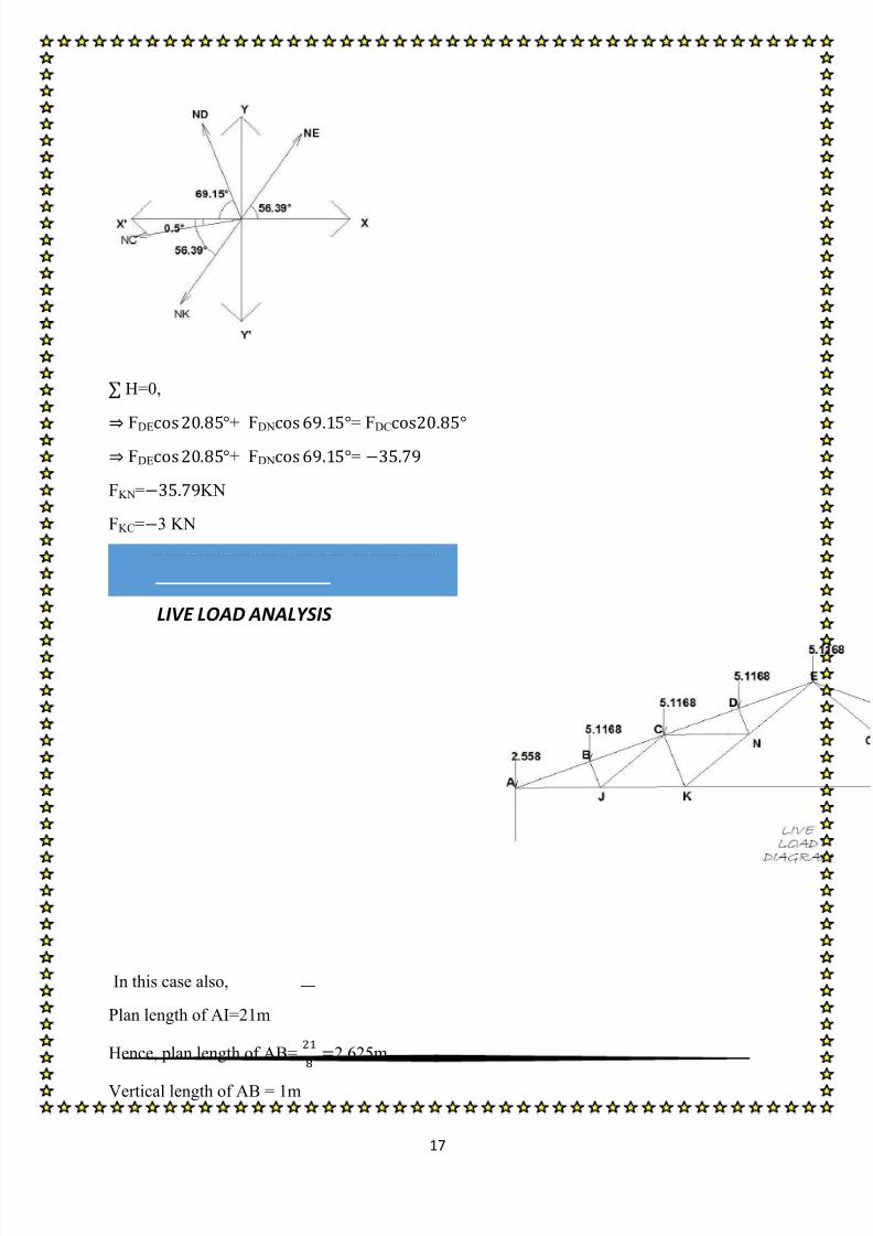
Consideri ng Poin t N: -
V=0,
FDE FDN= FDC
FDE FDN=
8/13/2019 Steel Designing Project
http://slidepdf.com/reader/full/steel-designing-project 18/84
17
LIVE LOAD ANALYSIS
H=0,
FDE
+ FDN
= FDC
FDE + FDN =
FKN=KN
FKC=3 KN
In this case also,
Plan length of AI=21m
Hence, plan length of AB=
2.625m
Vertical length of AB = 1m

8/13/2019 Steel Designing Project
http://slidepdf.com/reader/full/steel-designing-project 19/84
18
Now we will evaluate & find out the member loads considering each points.
As the structure is having symmetrical loading, then →
R A=R I=
KN
Consideri ng Poin t A: -
V=0,
FAB FAJ= -R A+1.87
FAB FAJ=
H=0,
FAB+ FAJ= 0
FAB FAJ= 0
FAB=51.53KN
FAJ=48.22KN
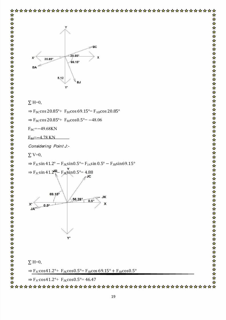
Consideri ng Poin t B: -
V=0,
FBC FBJ= FAB
FBC FBJ= 13.22
8/13/2019 Steel Designing Project
http://slidepdf.com/reader/full/steel-designing-project 20/84
19
H=0,
FBC + FBJ = FAB FBC + FBJ= 48.06
FBC=49.68KN
FBJ=4.78 KN
Consideri ng Poin t J:-
V=0,
FJC FJK = FJA FJB
FJC FJK =
H=0,
FJC+ FJK = FJB FJB
FJC+ FJK =

8/13/2019 Steel Designing Project
http://slidepdf.com/reader/full/steel-designing-project 21/84
20
FBC=6.72KN
FBJ=52.8 KN
Taking a section 11’
M=0,
FKL ( )
FKL=27.22KN
Consideri ng Poin t K: -
V=0,
FKN FKC = FJK
FKN FKC =
H=0,
FKN + FKC= FJK FKL
FKN + FKC=
FKN=47.72KN
FKC=42.19 KN
Considering Point C:-
V=0,
FCD FCN= FCK FCB FCJ
FCD FCN=
8/13/2019 Steel Designing Project
http://slidepdf.com/reader/full/steel-designing-project 22/84

8/13/2019 Steel Designing Project
http://slidepdf.com/reader/full/steel-designing-project 23/84
22
H=0,
FDE + FDN = FDC
FDE + FDN =
FKN=KN
FKC=4.78 KN
Consideri ng Poin t N: -
V=0,
FDE FDN= FDC
F NE=KN

8/13/2019 Steel Designing Project
http://slidepdf.com/reader/full/steel-designing-project 24/84
23
WIND LOAD ANALYSIS
WL θ=90° EG Cpi=0.2
In this case also, Plan length of AI=21m
Hence, plan length of AB=
2.625m
Vertical length of AB = 1m
Now we will evaluate & find out the member loads considering each points.
As the structure is having symmetrical loading, then →
R A=R I=
KN
Consideri ng Poin t A: -
V=0,
FAB FAJ= R A1.63
H=0,
8/13/2019 Steel Designing Project
http://slidepdf.com/reader/full/steel-designing-project 25/84
24
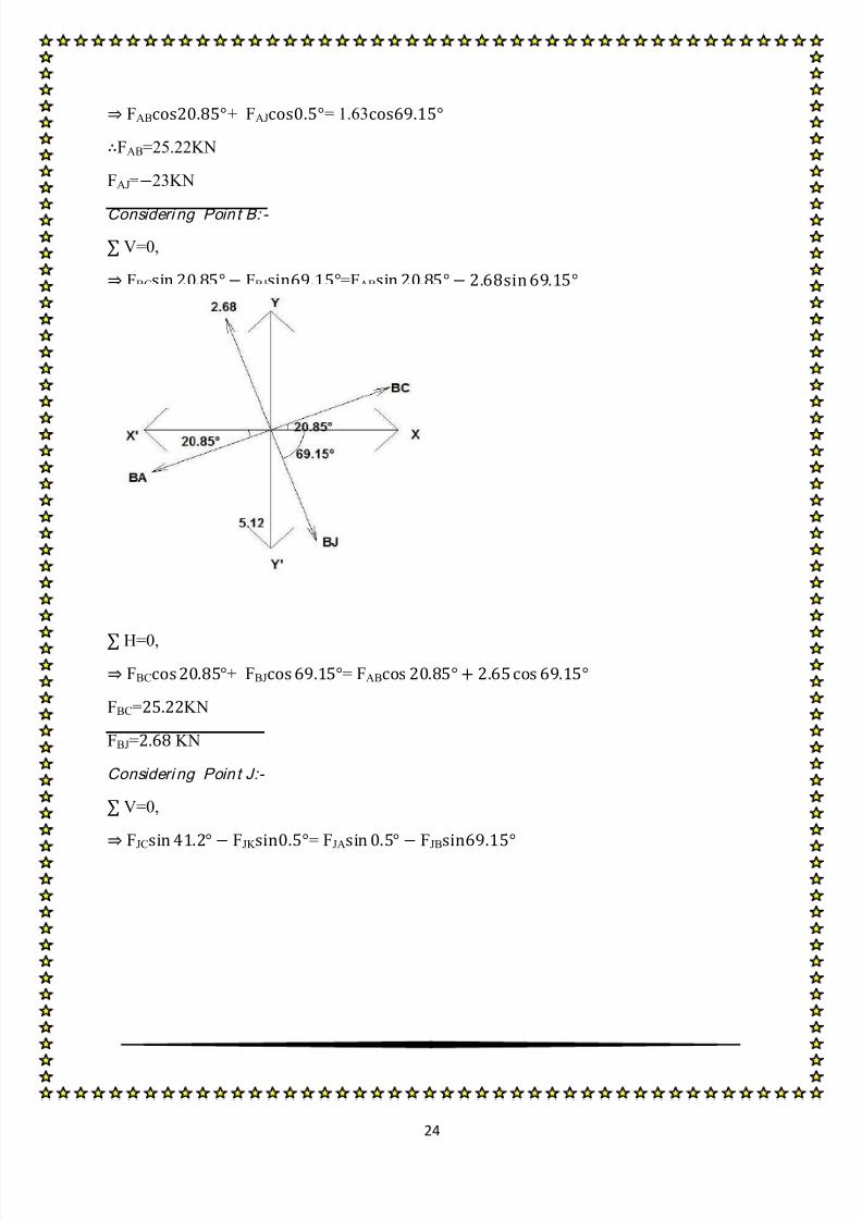
FAB+ FAJ= 1.63
FAB=25.22KN
FAJ=23KN
Consideri ng Poin t B: -
V=0,
FBC FBJ=FAB
H=0,
FBC + FBJ = FAB
FBC=KN
FBJ= KN
Consideri ng Poin t J:-
V=0,
FJC FJK = FJA FJB

8/13/2019 Steel Designing Project
http://slidepdf.com/reader/full/steel-designing-project 26/84
25
H=0,
FJC+ FJK = FJB FJA
FBC=KN
FBJ= KN
Taking a section 11’
M=0,
FKL
(
)
FKL=11.3KN
Consideri ng Poin t K: -
V=0,
FKN FKC = FJK

8/13/2019 Steel Designing Project
http://slidepdf.com/reader/full/steel-designing-project 27/84
26
H=0,
FKN + FKC= FJK FKL
FKN=33.44KN
FKC= KN
Considering Point C:-
V=0,
FCD FCN=FCK FCB FCJ
H=0,
FCD+FCN= FCB FCJ FCK
FKN=70.1KN

8/13/2019 Steel Designing Project
http://slidepdf.com/reader/full/steel-designing-project 28/84
27
FKC=97.82 KN
Consideri ng Poin t D: -
V=0,
FDE FDN= FDC
H=0,
FDE + FDN = FDC
FKN=
FKC= KN
Consideri ng Poin t N: -

8/13/2019 Steel Designing Project
http://slidepdf.com/reader/full/steel-designing-project 29/84
28
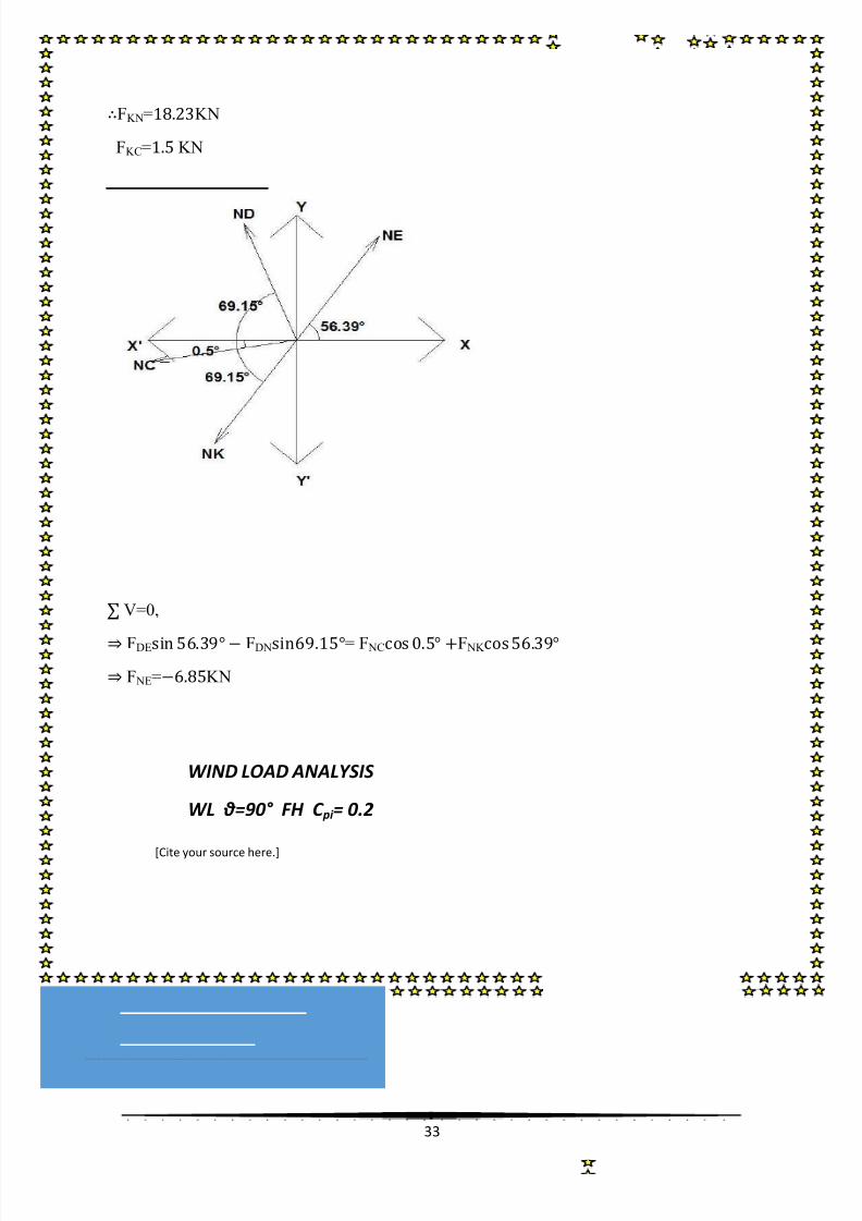
WIND LOAD ANALYSIS
WL θ=90° EG C pi = -0.2
[Cite your source here.]
V=0,
FDE FDN= F NC F NK
F NE=KN
In this case also,
Plan length of AI=21m

8/13/2019 Steel Designing Project
http://slidepdf.com/reader/full/steel-designing-project 30/84
29
Hence, plan length of AB=
2.625m
Vertical length of AB = 1m
Now we will evaluate & find out the member loads considering each points.
As the structure is having symmetrical loading, then →
R A=R I=
KN
Consideri ng Poin t A: -
V=0,
FAB FAJ= R A0.91
H=0,
FAB+ FAJ= 0.91
FAB=14.1KN
FAJ=12.84KN
Consideri ng Poin t B: -
V=0,
FBC FBJ=FAB
H=0,
FBC + FBJ = FAB
FBC=KN

8/13/2019 Steel Designing Project
http://slidepdf.com/reader/full/steel-designing-project 31/84
30
FBJ= KN
Consideri ng Poin t J:-
V=0,
FJC FJK = FJA FJB
H=0,
FJC+ FJK = FJB FJA
FBC=KN
FBJ= KN
Taking a section 11’
M=0,

8/13/2019 Steel Designing Project
http://slidepdf.com/reader/full/steel-designing-project 32/84
31
FKL( )
FKL=6..3KN
Consideri ng Poin t K: -
V=0,
FKN FKC = FJK
H=0,
FKN + FKC= FJK FKL
FKN=KN
FKC= KN
Considering Point C:-
V=0,
FCD FCN=FCK FCB FCJ

8/13/2019 Steel Designing Project
http://slidepdf.com/reader/full/steel-designing-project 33/84
32
H=0,
FCD+FCN= FCB FCJ FCK
FKN=KN
FKC= KN
Consideri ng Poin t D: -
V=0,
FDE FDN= FDC
H=0,
FDE + FDN = FDC
8/13/2019 Steel Designing Project
http://slidepdf.com/reader/full/steel-designing-project 34/84
33
WIND LOAD ANALYSIS
WL θ=90° FH C pi = 0.2
[Cite your source here.]
FKN=KN
FKC= KN
Consideri ng Poin t N: -
V=0,
FDE FDN= F NC F NK
F NE=KN

8/13/2019 Steel Designing Project
http://slidepdf.com/reader/full/steel-designing-project 35/84
34
In this case also,
Plan length of AI=21m
Hence, plan length of AB=
2.625m
Vertical length of AB = 1m
Now we will evaluate & find out the member loads considering each points.
As the structure is having symmetrical loading, then →
R A=R I=
KN
Consideri ng Poin t A: -
V=0,
FAB FAJ= R A1.45
H=0,

8/13/2019 Steel Designing Project
http://slidepdf.com/reader/full/steel-designing-project 36/84
35
FAB+ FAJ= 1.45
FAB=22.37KN
FAJ=20.39KN
Consideri ng Poin t B: -
V=0,
FBC FBJ=FAB
H=0,
FBC + FBJ = FAB
FBC=KN
FBJ=2.38 KN
Consideri ng Poin t J:-
V=0,
FJC FJK = FJA FJB

8/13/2019 Steel Designing Project
http://slidepdf.com/reader/full/steel-designing-project 37/84
36
H=0,
FJC+ FJK = FJB FJA
FJC=KN
FJK = KN
Taking a section 11’
M=0,
FKL ( )
FKL=8.1KN
Consideri ng Poin t K: -
V=0,
FKN FKC = FJK
H=0,
FKN + FKC= FJK FKL
FKN=KN
FKC= KN
Considering Point C:-
V=0,
FCD FCN=FCK FCB FCJ

8/13/2019 Steel Designing Project
http://slidepdf.com/reader/full/steel-designing-project 38/84
37
H=0,
FCD+FCN= FCB FCJ FCK
FKN=KN
FKC= KN
Consideri ng Poin t D: -
V=0,
FDE FDN= FDC
H=0,
FDE + FDN = FDC
FDE=KN

8/13/2019 Steel Designing Project
http://slidepdf.com/reader/full/steel-designing-project 39/84
38
WIND LOAD ANALYSIS
WL θ=90° FH C pi = - 0.2
[Cite your source here.]
FDN= KN
Consideri ng Poin t N: -
V=0,
FDE FDN= F NC F NK
F NE=KN
8/13/2019 Steel Designing Project
http://slidepdf.com/reader/full/steel-designing-project 40/84
39
In this case also,
Plan length of AI=21m
Hence, plan length of AB=
2.625m
Vertical length of AB = 1m
Now we will evaluate & find out the member loads considering each points.
As the structure is having symmetrical loading, then →
R A=R I=
KN
Consideri ng Poin t A: -
V=0,
FAB FAJ= R A0.72
H=0,
FAB+ FAJ= 0.72

8/13/2019 Steel Designing Project
http://slidepdf.com/reader/full/steel-designing-project 41/84
40
FAB=11.28KN
FAJ=10.29KN
Consideri ng Poin t B: -
V=0,
FBC FBJ=FAB
H=0,
FBC + FBJ = FAB
FBC=KN
FBJ=1.2 KN
Consideri ng Poin t J:-
V=0,
FJC FJK = FJA FJB

8/13/2019 Steel Designing Project
http://slidepdf.com/reader/full/steel-designing-project 42/84
41
H=0,
FJC+ FJK = FJB FJA
FJC=KN
FJK = KN
Taking a section 11’
M=0,
FKL( )
FKL=5.1KN
Consideri ng Poin t K: -
V=0,
FKN FKC = FJK

8/13/2019 Steel Designing Project
http://slidepdf.com/reader/full/steel-designing-project 43/84
42
H=0,
FKN + FKC= FJK FKL
FKN=KN
FKC= KN
Considering Point C:-
V=0,
FCD FCN=FCK FCB FCJ
H=0,
FCD+FCN= FCB FCJ FCK

8/13/2019 Steel Designing Project
http://slidepdf.com/reader/full/steel-designing-project 44/84
43
FCD=KN
FCN= KN
Consideri ng Poin t D: -
V=0,
FDE FDN= FDC
H=0,
FDE + FDN = FDC
FDE=KN
FDN= KN
Consideri ng Poin t N: -

8/13/2019 Steel Designing Project
http://slidepdf.com/reader/full/steel-designing-project 45/84
44
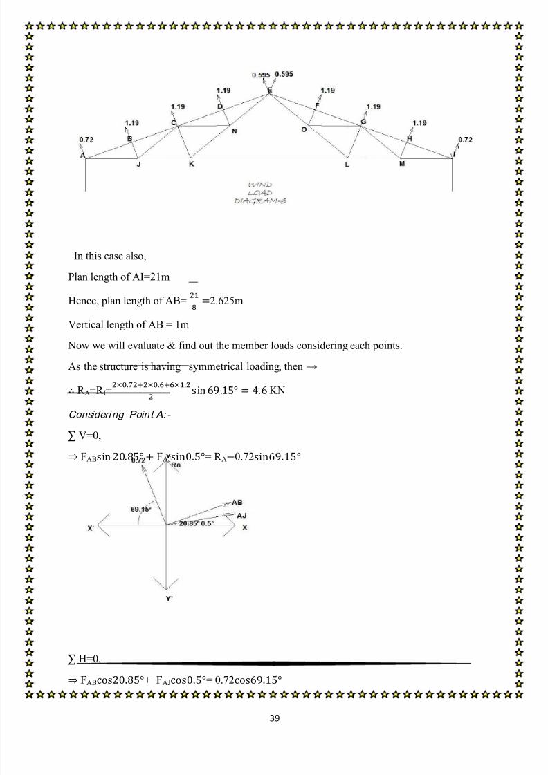
WIND LOAD ANALYSIS
Θ=0°
[Cite your source here.]
V=0,
FDE FDN= F NC F NK
F NE=KN
In this case also,
Plan length of AI=21m
Hence, plan length of AB=
2.625m
Vertical length of AB = 1m
Now we will evaluate & find out the member loads considering each points.
Here, we get R A=6.785 KN
R B=6.985 KN
Consideri ng Poin t A: -
V=0,
FAB FAJ= R A1.03

8/13/2019 Steel Designing Project
http://slidepdf.com/reader/full/steel-designing-project 46/84
45
H=0,
FAB+ FAJ= 1.03
FAB=15.76KN
FAJ=13.9KN
Consideri ng Poin t B: -
V=0,
FBC FBJ=FAB
H=0,
FBC + FBJ = FAB
FBC=KN
FBJ= KN
8/13/2019 Steel Designing Project
http://slidepdf.com/reader/full/steel-designing-project 47/84
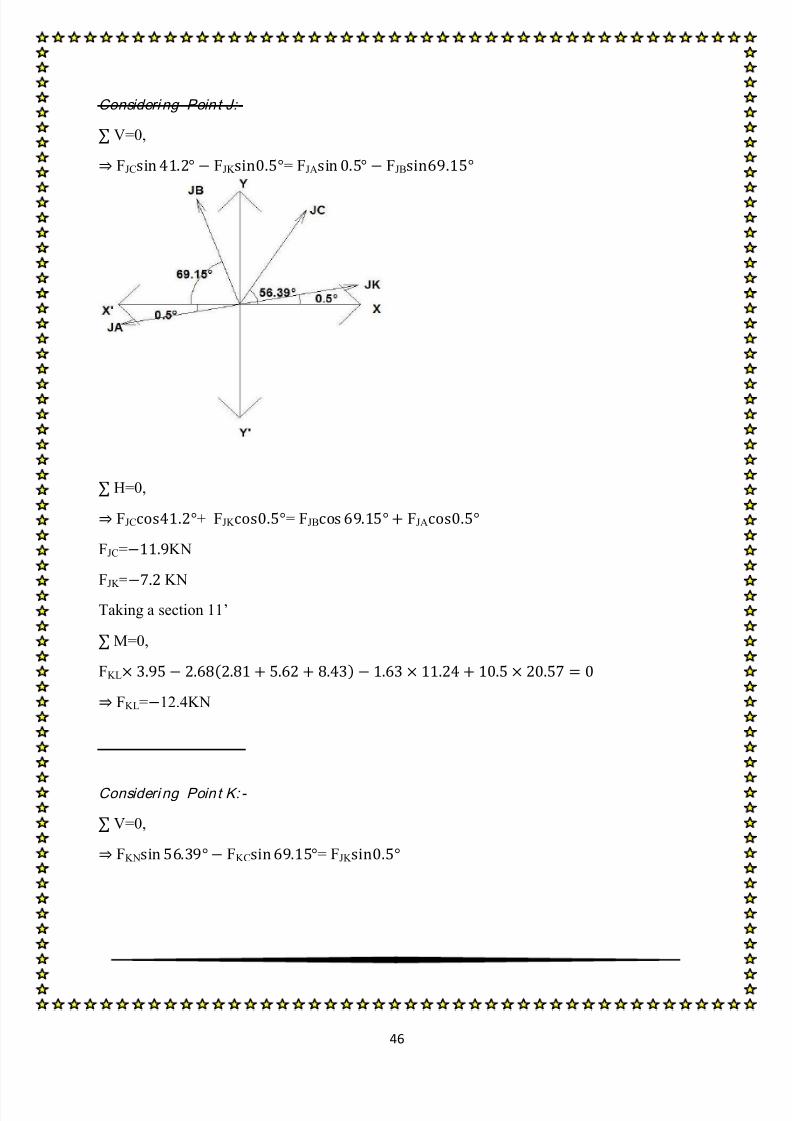
46
Consideri ng Poin t J:-
V=0,
FJC FJK = FJA FJB
H=0,
FJC+ FJK = FJB FJA
FJC=KN
FJK =
KN
Taking a section 11’
M=0,
FKL ( )
FKL=12.4KN
Consideri ng Poin t K: -
V=0,
FKN FKC = FJK

8/13/2019 Steel Designing Project
http://slidepdf.com/reader/full/steel-designing-project 48/84
47
H=0,
FKN + FKC= FJK FKL
FKN=KN
FKC= KN
Considering Point C:-
V=0,
FCD FCN=FCK FCB FCJ
H=0,
FCD+FCN= FCB FCJ FCK
FCD=KN

8/13/2019 Steel Designing Project
http://slidepdf.com/reader/full/steel-designing-project 49/84
48
FCN= KN
Consideri ng Poin t D: -
V=0,
FDE FDN= FDC
H=0,
FDE + FDN = FDC
FDE=
FDN= KN
Consideri ng Poin t N: -

8/13/2019 Steel Designing Project
http://slidepdf.com/reader/full/steel-designing-project 50/84
49
WIND LOAD ANALYSIS
Θ=0°
[Cite your source here.]
V=0,
FDE FDN= F NC F NK
F NE=KN
In this case also,
Plan length of AI=21m
Hence, plan length of AB=
2.625m
Vertical length of AB = 1m
Now we will evaluate & find out the member loads considering each points.
Here, we get R A=2.03 KN
R B=2.18 KN
Consideri ng Poin t A: -
V=0,
FAB FAJ= R A0.3

8/13/2019 Steel Designing Project
http://slidepdf.com/reader/full/steel-designing-project 51/84
50
H=0,
FAB+ FAJ= 0.3 FAB=5.79KN
FAJ=4.89KN
Consideri ng Poin t B: -
V=0,
FBC FBJ=FAB
H=0,
FBC + FBJ = FAB
FBC=KN
FBJ= KN
Consideri ng Poin t J:-

8/13/2019 Steel Designing Project
http://slidepdf.com/reader/full/steel-designing-project 52/84
8/13/2019 Steel Designing Project
http://slidepdf.com/reader/full/steel-designing-project 53/84
52
H=0,
FKN + FKC= FJK FKL
FKN=KN
FKC= KN
Considering Point C:-
V=0,
FCD FCN=FCK FCB FCJ
H=0,
FCD+FCN= FCB FCJ FCK
FCD=KN
FCN= KN

8/13/2019 Steel Designing Project
http://slidepdf.com/reader/full/steel-designing-project 54/84
53
Consideri ng Poin t D: -
V=0,
FDE FDN= FDC
H=0,
FDE + FDN = FDC
FDE=
FDN= KN
Consideri ng Poin t N: -

8/13/2019 Steel Designing Project
http://slidepdf.com/reader/full/steel-designing-project 55/84
54
V=0,
FDE FDN= F NC F NK
F NE=KN
factored compressive load =335.175 KN
The angle belongs to buckling class ‘c’(from IS -800-2007,table 10). f cd varies from 227 to 24.3 MPa
depending on ⁄ .
Assuming f cd =100 N/mm2
Ac=
mm
2
Since we will be using double angle on the same side of the gusset plate.
DESIGNING OF MEMBERS
DESIGN OF MEMBER cd fG
• COMPRESSION DESIGN
• TENSION DESIGN
Compressive load on CD and FG member
• = 335.175 KN
Tensile load on the CD and FG member
• =37.48 KN

8/13/2019 Steel Designing Project
http://slidepdf.com/reader/full/steel-designing-project 56/84
55
so area of each angle = 3351.75/2 = 1675.875
As this is the double angle rafter so the section must be joined on a single side of a gusset plate of
thickness 8mm and the dimension of the angle is 110×110×12 @ 19.7 kg/m. The angles are joined
by fillet welding.
As per IS 800:2007 SECTION 7 clause no. 7.5.1.2 and 7.1.2.1 and table 5, 7, 10, 12
λ c=2 2
1 2 3vvk k k
2810
21.5 1.461 88.812
250
l
r vv
vv E
1 2 110 110
2 2 12 0.1031 88.812
250
b b
t
E
For hinge support we have ,k 1=0.70, k 2=0.60, k 3=5.
2 20.70 0.60 1.46 5 0.103 1.425e
Again for fixed support we have, k 1=0.20, k 2=0.35, k 3=20.
2 20.20 0.35 1.46 20 0.103 1.076e
It is given in the IS-800-2007 that
ϕ = 0.5[1+0.49(1.251-0.2) +1.2512] = 1.539
• DESIGN FOR COMPRESSIVEFORCE
IS code specification
•For partial restraint, the λe can be interpolated between the λe results for fixed & hingedcases.
the interpolated result
•λe=1.251
8/13/2019 Steel Designing Project
http://slidepdf.com/reader/full/steel-designing-project 57/84
56
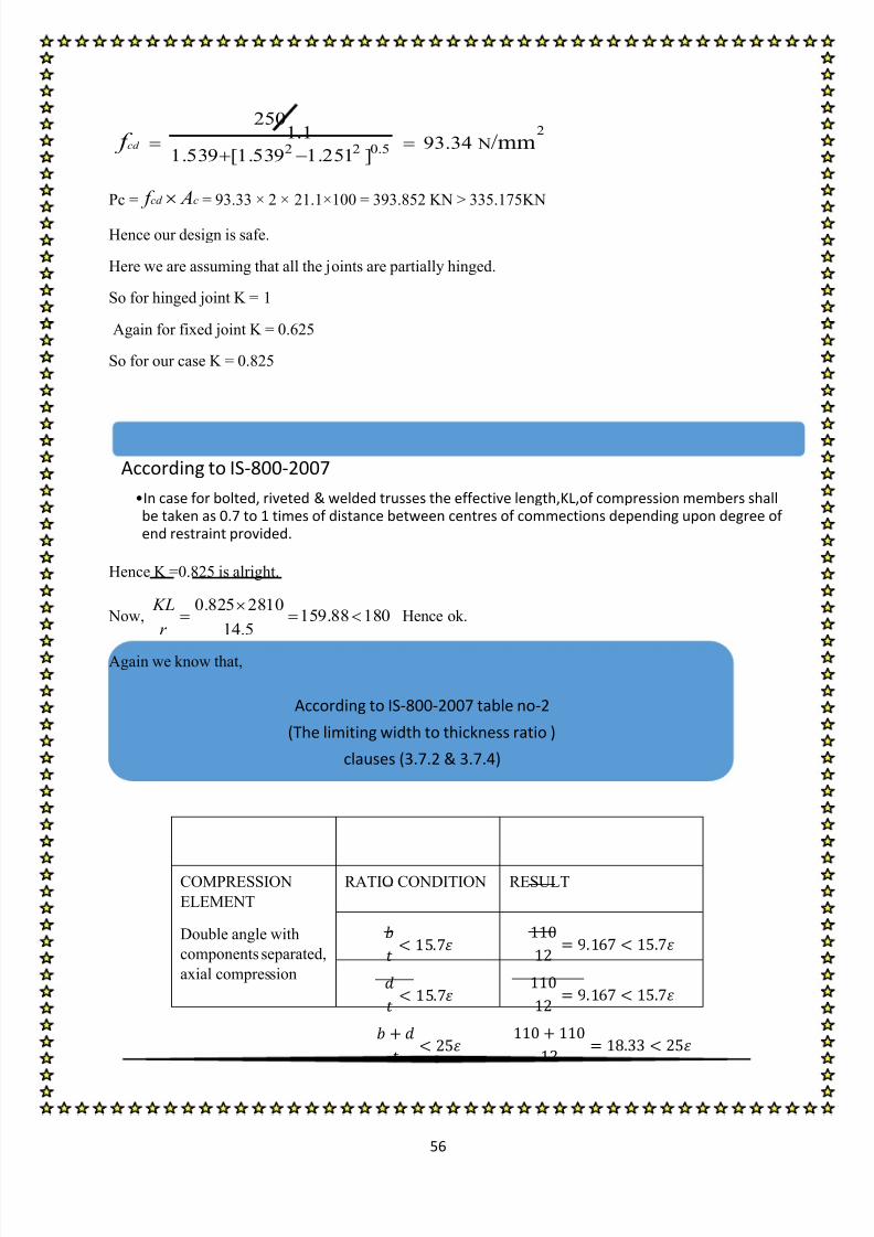
2
2 2 0.5 N
2501.1
93.341.539 [1.539 1.251 ]
/mmcd f
Pc = cd c f A = 93.33 × 2 × 21.1×100 = 393.852 KN > 335.175KN
Hence our design is safe.
Here we are assuming that all the joints are partially hinged.
So for hinged joint K = 1
Again for fixed joint K = 0.625
So for our case K = 0.825
Hence K =0.825 is alright.
Now,0.825 2810
159.88 18014.5
KL
r
Hence ok.
Again we know that,
COMPRESSION
ELEMENT
RATIO CONDITION RESULT
Double angle with
components separated,
axial compression
According to IS-800-2007
•In case for bolted, riveted & welded trusses the effective length,KL,of compression members shallbe taken as 0.7 to 1 times of distance between centres of commections depending upon degree ofend restraint provided.
According to IS-800-2007 table no-2
(The limiting width to thickness ratio )
clauses (3.7.2 & 3.7.4)

8/13/2019 Steel Designing Project
http://slidepdf.com/reader/full/steel-designing-project 58/84
57
Hence our assumed section is ok.
From IS 800:2007 clause 10.5.7.1.1
2
1
410
189.3713 1.25
N/mm3
uwd
m
f f
Maximum size of welding (a) = 8−1.5 = 6.5 mm
Minimum size of welding (a) = 5 mm
So, taking weld size of 6 mm
Then t =0.7×a = 0.7×4 = 4.2 mm
Now,
Shearing area at the throat × design shear strength of the weld = design load
2×L×t×189.371= 335.175×10³
L = 335.175 1000
210.72 4.2 189.371
mm
So we have to provide 225 mm length of welding.
.
Factored tensile load = 37.48×1.5=56.22 KN
DESIGN OF WELDED JOINTS
• DESIGN FOR TENSILESTRENGTH
TENSION
As per IS 800: 2007 SECTION 6 clause 6.1, 6.2 and 6.3.3
Design strength due to Yielding of Gross Section,
Tdg = Ag × f y/γm0
• Hence we can can find out the trial area for the design form this.

8/13/2019 Steel Designing Project
http://slidepdf.com/reader/full/steel-designing-project 59/84
58
25.1 250 100570.454
1.1
g y
dg
mo
dg
A f T
T KN
From IS 800:2007 clause 10.5.7.1.1
2
1
410
189.3713 1.25
N/mm3
uwd
m
f f
Maximum size of welding (a) = 8−1.5 = 6.5 mm Minimum size of welding (a) = 5 mm
So, taking weld size of 6 mm
Then t =0.7×a = 0.7×6 = 4.2 mm
Now,
Shearing area at the throat × design shear strength of the weld = design load
2×L×t×189.371= 56.22×10³
L = 56.22 1000 35.342 4.2 189.371
mm
So as we have provided 225 mm length of welding , so it is ok.
Here bs = 110 mm, and Lc = 175 mm, W = 110 mm, t = 12 mm, f y =250N/mm2 , and f u = 410 N/mm
2
0.7≰ β =1.19
β = 1.19
0.9 (110 12) 12 410 1.19 (110 12) 12 250 665.2091.25 1.1
dnT KN
DESIGN OF WELDED JOINTS
Design strength due to Rupture of Critical Section
Tdn = 0.9Anc× f u/γm1+β×Ago× f y/γm0 Where, β = 1.4−0.076× (w/t)×(f y/f u)× (bs/Lc)
8/13/2019 Steel Designing Project
http://slidepdf.com/reader/full/steel-designing-project 60/84
59
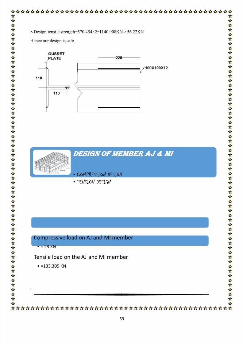
Design tensile strength=570.454×2=1140.908KN > 56.22KN
Hence our design is safe.
.
DESIGN OF MEMBER aj mi
• COMPRESSION DESIGN
• TENSION DESIGN
Compressive load on AJ and MI member
• = 23 KN
Tensile load on the AJ and MI member
• =133.305 KN

8/13/2019 Steel Designing Project
http://slidepdf.com/reader/full/steel-designing-project 61/84
60
factored compressive load =23×1.5=34.5 KN
The angle belongs to buckling class ‘c’(from IS -800-2007,table 10). f cd varies from 227 to 24.3 MPa
depending on ⁄ .
Assuming f cd =100 N/mm2
Ac=
mm
2
Since we will be using double angle so area of each angle = 345/2 = 172.5
As this is the double angle rafter so the section must be joined on a single side of a gusset plate of
thickness 8mm and the dimension of the angle is 70×70×6 @ 6.3 kg/m. The angles are joined byfillet welding
As per IS 800:2007 SECTION 7 clause no. 7.5.1.2 and 7.1.2.1 and table 5, 7, 10, 12
λ c=2 2
1 2 3vvk k k
2865
13.6 2.371 88.812
250
l
r vv
vv E
1 2 70 70
2 2 6 0.1311 88.812
250
b b
t
E
For hinge support we have ,k 1=0.70, k 2=0.60, k 3=5.
2 20.70 0.60 2.37 5 0.131 2.038e
Again for fixed support we have, k 1=0.20, k 2=0.35, k 3=20.
2 20.20 0.35 2.37 20 0.131 1.584e
It is given in the IS-800-2007 that
• DESIGN FOR COMPRESSIVEFORCE
IS code specification
•For partial restraint, the λe can be interpolated between the λe results for fixed & hingedcases.
the interpolated result
•λe=1.811

8/13/2019 Steel Designing Project
http://slidepdf.com/reader/full/steel-designing-project 62/84
61
ϕ = 0.5[1+0.49(1.811-0.2) +1.8112] = 2.534
2
2 2 0.5 N
2501.1
52.8542.534 [2.534 1.811 ]
/mmcd
f
Pc = cd c f A = 52.854 × 2 × 8.06×100 = 85.2 KN > 34.5KN
Hence our design is safe.
Here we are assuming that all the joints are partially hinged.
So for hinged joint K = 1
Again for fixed joint K = 0.65
So for our case K = 0.825
Hence K =0.825 is alright.
Now,0.825 2865
168.53 18013.6
KL
r
Hence ok.
Again we know that,
COMPRESSION
ELEMENT
RATIO CONDITION RESULT
Double angle with
components separated,
axial compression
According to IS-800-2007
•In case for bolted, riveted & welded trusses the effective length,KL,of compression members shallbe taken as 0.7 to 1 times of distance between centres of commections depending upon degree ofend restraint provided.
According to IS-800-2007 table no-2
(The limiting width to thickness ratio )
clauses (3.7.2 & 3.7.4)

8/13/2019 Steel Designing Project
http://slidepdf.com/reader/full/steel-designing-project 63/84
62
From IS 800:2007 clause 10.5.7.1.1
2
1
410
189.3713 1.25
N/mm3
uwd
m
f f
Maximum size of welding (a) = 8−1.5 = 6.5 mm
Minimum size of welding (a) = 3 mm
So, taking weld size of 4 mm
Then t =0.7×a = 0.7×4 = 2.8 mm
Now,
Shearing area at the throat × design shear strength of the weld = design load
4×L×t×189.371= 28.8×10³
L = 28.8 1000
38.02
4 2.8 189.371
mm
So we have to provide 40 mm length of welding.(as per IS Code).
Factored tensile load = 133.305 KN
DESIGN OF WELDED JOINTS
• DESIGN FOR TENSILESTRENGTH
TENSION

8/13/2019 Steel Designing Project
http://slidepdf.com/reader/full/steel-designing-project 64/84
63
8.06 100 250183.181
1.1
g y
dg
mo
dg
A f T
T KN
.
From IS 800:2007 clause 10.5.7.1.1
2
1
410
189.3713 1.25
N/mm3
uwd
m
f f
Maximum size of welding (a) = 8−1.5 = 6.5 mm
Minimum size of welding (a) = 3 mm
So, taking weld size of 4 mm
Then t =0.7×a = 0.7×4 = 2.8 mm
Now,
Shearing area at the throat × design shear strength of the weld = design load
4×L×t×189.371= 133.305×10³
L = 133.305 1000
62.854 2.8 189.371
mm
So we have to provide 75 mm length of welding.
As per IS 800: 2007 SECTION 6 clause 6.1, 6.2 and 6.3.3
Design strength due to Yielding of Gross Section,
Tdg = Ag × f y/γm0
• Hence we can can find out the trial area for the design form this.
DESIGN OF WELDED JOINTS

8/13/2019 Steel Designing Project
http://slidepdf.com/reader/full/steel-designing-project 65/84
64
Here bs = 70 mm, and Lc = 75 mm, W = 70 mm, t = 6 mm, f y =250N/mm2 , and f u = 410 N/mm
2
0.7≰ β = .89 ≤ (f uγm0/f yγm1)=1.44
β = 0.89
0.9 (70 6) 6 410 0.89 (70 6) 6 250191.02
1.25 1.1dn
T KN
Design tensile strength=183.181×2=366.362KN > 133.305KN
Hence our design is safe.
Design strength due to Rupture of Critical Section
Tdn = 0.9Anc× f u/γm1+β×Ago× f y/γm0
Where, β = 1.4−0.076× (w/t)×(f y/f u)× (bs/Lc)
DESIGN OF MEM BER kl
• COMPRESSION DESIGN
• TENSION DESIGN

8/13/2019 Steel Designing Project
http://slidepdf.com/reader/full/steel-designing-project 66/84
65
.
factored compressive load =11.3×1.5=16.95 KN
The angle belongs to buckling class ‘c’(from IS -800-2007,table 10). f cd varies from 227 to 24.3 MPa
depending on ⁄ .
Assuming f cd =100 N/mm2
Ac=
mm
2
Since we will be using double angle so area of each angle = 169.5/2 = 84.75
As this is the double angle rafter so the section must be joined on a single side of a gusset plate of
thickness 8mm and the dimension of the angle is 200×200×20 @ 4.5 kg/m. The angles are joined by
fillet welding
As per IS 800:2007 SECTION 7 clause no. 7.5.1.2 and 7.1.2.1 and table 5, 7, 10, 12
λ c=2 2
1 2 3vvk k k
9542
39.3 2.7341 88.812
250
l
r vv
vv E
Compressive load on KL member• = 11.3 KN
Tensile load on the KL member
• =65.16 KN
• DESIGN FOR COMPRESSIVEFORCE

8/13/2019 Steel Designing Project
http://slidepdf.com/reader/full/steel-designing-project 67/84
66
1 2 200 200
2 2 20 0.1121 88.812
250
b b
t
E
For hinge support we have ,k 1=0.70, k 2=0.60, k 3=5.
2 20.70 0.60 2.734 5 0.112 1.789e
Again for fixed support we have, k 1=0.20, k 2=0.35, k 3=20.
2 20.20 0.35 2.734 20 0.112 1.751e
It is given in the IS-800-2007 that
ϕ = 0.5[1+0.49(1.811-0.2) +1.8112] = 2.451
22 2 0.5 N
250
1.1 54.822.451 [2.451 1.77 ]
/mmcd f
Pc = cd c f A = 54.82 × 2 × 76.4×100 = 837.649 KN > 16.95KN
Hence our design is safe.
Here we are assuming that all the joints are partially hinged.
So for hinged joint K = 1
Again for fixed joint K = 0.65
So for our case K = 0.825
Hence K =0.825 is alright.
IS code specification
•For partial restraint, the λe can be interpolated between the λe results for fixed & hingedcases.
the interpolated result
•λe=1.77
According to IS-800-2007
•In case for bolted, riveted & welded trusses the effective length,KL,of compression members shallbe taken as 0.7 to 1 times of distance between centres of commections depending upon degree ofend restraint provided.

8/13/2019 Steel Designing Project
http://slidepdf.com/reader/full/steel-designing-project 68/84
67
Now,0.825 9542
194.24 25039.3
KL
r
Hence ok.
Again we know that,
COMPRESSION
ELEMENT
RATIO CONDITION RESULT
Double angle with
components separated,
axial compression
From IS 800:2007 clause 10.5.7.1.1
2
1
410
189.3713 1.25
N/mm3
uwd
m
f f
Maximum size of welding (a) = 8−1.5 = 6.5 mm
Minimum size of welding (a) = 5 mm
So, taking weld size of 6 mm
Then t =0.7×a = 0.7×6 = 4.2 mm
Now,
Shearing area at the throat × design shear strength of the weld = design load
4×L×t×189.371= 28.8×10³
L = 16.95 1000
3.894 4.2 189.371
mm
According to IS-800-2007 table no-2(The limiting width to thickness ratio )
clauses (3.7.2 & 3.7.4)
DESIGN OF WELDED JOINTS

8/13/2019 Steel Designing Project
http://slidepdf.com/reader/full/steel-designing-project 69/84
68
So we have to provide 40 mm length of welding.(as per IS Code).
Factored tensile load = 65.16 KN
76.4 100 250 1736.361.1
g y
dg
mo
dg
A f T
T KN
.
From IS 800:2007 clause 10.5.7.1.1
2
1
410
189.3713 1.25
N/mm3
uwd
m
f f
Maximum size of welding (a) = 8−1.5 = 6.5 mm
Minimum size of welding (a) = 5 mm
So, taking weld size of 6 mm
Then t =0.7×a = 0.7×6 = 4.2 mm
Now,
Shearing area at the throat × design shear strength of the weld = design load
• DESIGN FOR TENSILESTRENGTH
TENSION
As per IS 800: 2007 SECTION 6 clause 6.1, 6.2 and 6.3.3
Design strength due to Yielding of Gross Section,
Tdg = Ag × f y/γm0
• Hence we can can find out the trial area for the design form this.
DESIGN OF WELDED JOINTS

8/13/2019 Steel Designing Project
http://slidepdf.com/reader/full/steel-designing-project 70/84
69
4×L×t×189.371= 65.16×10³
L = 65.16 1000
40.962 4.2 189.371
mm
So we have to provide 350 mm length of welding.
Here bs = 200 mm, and Lc = 350 mm, W = 200 mm, t = 20 mm, f y =250N/mm2 , and f u = 410 N/mm2
0.7≰ β = 1.135 ≤ (f uγm0/f yγm1)
β = 1.135
0.9 (200 20) 20 410 1.135 (200 20) 20 2501991.35
1.25 1.1dn
T KN
Design tensile strength=1736.36×2=3472.72KN > > 65.16KN
Hence our design is safe.
Design strength due to Rupture of Critical Section
Tdn = 0.9Anc× f u/γm1+β×Ago× f y/γm0
Where, β = 1.4−0.076× (w/t)×(f y/f u)× (bs/Lc)

8/13/2019 Steel Designing Project
http://slidepdf.com/reader/full/steel-designing-project 71/84
70
.
factored compressive load =103.631 KN
The angle belongs to buckling class ‘c’(from IS -800-2007,table 10). f cd varies from 227 to 24.3 MPa
depending on ⁄ .
Assuming f cd =100 N/mm2
Ac=
mm
2
Since we will be using double angle so area of each angle = 1036.31/2 = 518.155
As this is the double angle rafter so the section must be joined on a single side of a gusset plate of
thickness 8mm and the dimension of the angle is 70×70×8 @ 8.3 kg/m. The angles are joined by
fillet welding
As per IS 800:2007 SECTION 7 clause no. 7.5.1.2 and 7.1.2.1 and table 5, 7, 10, 12
λ c=2 2
1 2 3vvk k k
DESIGN OF MEMBER ck lg
• COMPRESSION DESIGN
• TENSION DESIGN
Compressive load on CK and LG member
• = 103.631 KN
Tensile load on the CK and LG member
• =8.97 KN
• DESIGN FOR COMPRESSIVEFORCE
8/13/2019 Steel Designing Project
http://slidepdf.com/reader/full/steel-designing-project 72/84
71
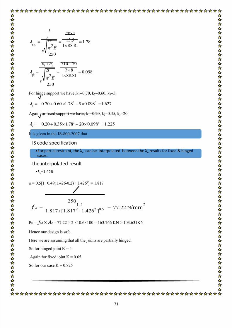
2084
13.5 1.781 88.812
250
l
r vv
vv E
1 2 710 70
2 2 8 0.0981 88.812
250
b b
t
E
For hinge support we have ,k 1=0.70, k 2=0.60, k 3=5.
2 20.70 0.60 1.78 5 0.098 1.627e
Again for fixed support we have, k 1=0.20, k 2=0.35, k 3=20.
2 20.20 0.35 1.78 20 0.098 1.225e
It is given in the IS-800-2007 that
ϕ = 0.5[1+0.49(1.426-0.2) +1.4262] = 1.817
2
2 2 0.5 N
2501.1
77.221.817 [1.817 1.426 ]
/mmcd f
Pc = cd c f A = 77.22 × 2 ×10.6×100 = 163.766 KN > 103.631KN
Hence our design is safe.
Here we are assuming that all the joints are partially hinged.
So for hinged joint K = 1
Again for fixed joint K = 0.65
So for our case K = 0.825
IS code specification
•For partial restraint, the λe can be interpolated between the λe results for fixed & hingedcases.
the interpolated result
•λe=1.426

8/13/2019 Steel Designing Project
http://slidepdf.com/reader/full/steel-designing-project 73/84
72
Hence K =0.825 is alright.
Now,0.825 2084
123.49 18013.5
KL
r
Hence ok.
Again we know that,
COMPRESSION
ELEMENT
RATIO CONDITION RESULT
Double angle with
components separated,
axial compression
From IS 800:2007 clause 10.5.7.1.1
2
1
410
189.3713 1.25
N/mm3
uwd
m
f f
Maximum size of welding (a) = 8−1.5 = 6.5 mm
Minimum size of welding (a) = 5 mm
So, taking weld size of 6 mm
Then t =0.7×a = 0.7×6 = 4.2 mm
Now,
According to IS-800-2007
•In case for bolted, riveted & welded trusses the effective length,KL,of compression members shallbe taken as 0.7 to 1 times of distance between centres of commections depending upon degree ofend restraint provided.
According to IS-800-2007 table no-2
(The limiting width to thickness ratio )
clauses (3.7.2 & 3.7.4)
DESIGN OF WELDED JOINTS
8/13/2019 Steel Designing Project
http://slidepdf.com/reader/full/steel-designing-project 74/84
73
Shearing area at the throat × design shear strength of the weld = design load
2×L×t×189.371= 103.631×10³
L = 103.631 1000
65.172 4.2 189.371
mm
So we have to provide 75 mm length of welding.
Factored tensile load = 8.97×1.5=13.455 KN
10.6 100 250240.9
1.1
g y
dg
mo
dg
A f T
T KN
.
From IS 800:2007 clause 10.5.7.1.1
2
1
410
189.3713 1.25
N/mm3
uwd
m
f f
Maximum size of welding (a) = 8−1.5 = 6.5 mm
Minimum size of welding (a) = 3 mm
• DESIGN FOR TENSILESTRENGTH
TENSION
As per IS 800: 2007 SECTION 6 clause 6.1, 6.2 and 6.3.3
Design strength due to Yielding of Gross Section,
Tdg = Ag × f y/γm0
• Hence we can can find out the trial area for the design form this.
DESIGN OF WELDED JOINTS

8/13/2019 Steel Designing Project
http://slidepdf.com/reader/full/steel-designing-project 75/84
74
So, taking weld size of 4 mm
Then t =0.7×a = 0.7×4 = 2.8 mm
Now,
Shearing area at the throat × design shear strength of the weld = design load4×L×t×189.371= 13.455×10
3
L = 13.455 1000
6.3434 2.8 189.371
mm
So we have to provide 75 mm length of welding.
Here bs = 70 mm, and Lc = 75 mm, W = 70 mm, t = 8 mm, f y =250N/mm2 , and f u = 410 N/mm
2
0.7≰ β =1.021 ≤ (f uγm0/f yγm1)
β = 1.021
0.9 (70 8) 8 410 1.021 (70 8) 8 250261.513
1.25 1.1dn
T KN
Design tensile strength=240.9×2=481.8KN > 13.455 KN
Hence our design is safe.
Design strength due to Rupture of Critical Section
Tdn = 0.9Anc× f u/γm1+β×Ago× f y/γm0
Where, β = 1.4−0.076× (w/t)×(f y/f u)× (bs/Lc)

8/13/2019 Steel Designing Project
http://slidepdf.com/reader/full/steel-designing-project 76/84
75
.
factored compressive load =19.82×1.5=29.73 KN
The angle belongs to buckling class ‘c’(from IS -800-2007,table 10). f cd varies from 227 to 24.3 MPa
depending on ⁄ .
Assuming f cd =100 N/mm2
Ac=
mm
2
Since we will be using double angle so area of each angle = 345/2 = 172.5
As this is the double angle rafter so the section must be joined on a single side of a gusset plate of
thickness 8mm and the dimension of the angle is 70×70×6 @ 6.3 kg/m. The angles are joined by
fillet welding
As per IS 800:2007 SECTION 7 clause no. 7.5.1.2 and 7.1.2.1 and table 5, 7, 10, 12
DESIGN OF MEMBER CN GO
• COMPRESSION DESIGN
• TENSION DESIGN
Compressive load on CN and OG member• = 19.82 KN
Tensile load on the CN and OG member
• =275.925 KN
• DESIGN FOR COMPRESSIVEFORCE
8/13/2019 Steel Designing Project
http://slidepdf.com/reader/full/steel-designing-project 77/84

8/13/2019 Steel Designing Project
http://slidepdf.com/reader/full/steel-designing-project 78/84
77
Hence K =0.825 is alright.
Now,0.825 2865
168.53 18013.6
KL
r
Hence ok.
Again we know that,
COMPRESSION
ELEMENT
RATIO CONDITION RESULT
Double angle with
components separated,axial compression
From IS 800:2007 clause 10.5.7.1.1
2
1
410
189.3713 1.25
N/mm3
uwd
m
f f
Maximum size of welding (a) = 8−1.5 = 6.5 mm
Minimum size of welding (a) = 3 mm
So, taking weld size of 4 mm
Then t =0.7×a = 0.7×4 = 2.8 mm
According to IS-800-2007
•In case for bolted, riveted & welded trusses the effective length,KL,of compression members shallbe taken as 0.7 to 1 times of distance between centres of commections depending upon degree ofend restraint provided.
According to IS-800-2007 table no-2
(The limiting width to thickness ratio )
clauses (3.7.2 & 3.7.4)
DESIGN OF WELDED JOINTS
8/13/2019 Steel Designing Project
http://slidepdf.com/reader/full/steel-designing-project 79/84
78
Now,
Shearing area at the throat × design shear strength of the weld = design load
2×L×t×189.371= 19.82×10³
L = 19.83 1000 18.682 2.8 189.371
mm
So we have to provide 40 mm length of welding.
Factored tensile load = 275.925 KN
8.06 100 250183.181
1.1
g y
dg
mo
dg
A f T
T KN
.
From IS 800:2007 clause 10.5.7.1.1
2
1
410
189.3713 1.25
N/mm3
uwd
m
f f
Maximum size of welding (a) = 8−1.5 = 6.5 mm
• DESIGN FOR TENSILE
STRENGTH
TENSION
As per IS 800: 2007 SECTION 6 clause 6.1, 6.2 and 6.3.3
Design strength due to Yielding of Gross Section,
Tdg = Ag × f y/γm0
• Hence we can can find out the trial area for the design form this.
DESIGN OF WELDED JOINTS

8/13/2019 Steel Designing Project
http://slidepdf.com/reader/full/steel-designing-project 80/84
79
Minimum size of welding (a) = 3 mm
So, taking weld size of 4 mm
Then t =0.7×a = 0.7×4 = 2.8 mm
Now,Shearing area at the throat × design shear strength of the weld = design load
2×L×t×189.371= 275.925×10³
L = 275.925 1000
230.22 2.8 189.371
mm
So we have to provide 250 mm length of welding.
Here bs = 70 mm, and Lc = 250 mm, W = 70 mm, t = 8 mm, f y =250N/mm2 , and f u = 410 N/mm
2
0.7≰ β =1.21 ≤ (f uγm0/f yγm1)
β = 1.21
0.9 (70 8) 8 410 1.21 (70 8) 8 250282.819
1.25 1.1dn
T KN
Design tensile strength=183.181×2=366.362 > 275.925
Hence our design is safe.
Design strength due to Rupture of Critical Section
Tdn = 0.9Anc× f u/γm1+β×Ago× f y/γm0
Where, β = 1.4−0.076× (w/t)×(f y/f u)× (bs/Lc)

8/13/2019 Steel Designing Project
http://slidepdf.com/reader/full/steel-designing-project 81/84
80
.
Here we are supposed to find out the maximum load at minor & major axis. To do so we
need to do the load combinations for various condition. They are explained below→
LOAD COMBINATIONS
Load Types Major axis MAX. LOADING IN KN Type
1.5(DL+LL) 1.5×{(0.588+1.03)+5.12} × cos θ = 9.44 Tension
1.5(DL+WL 1) 1.5{(0.588+1.03) × cos θ − 1.68} = − 0.25 Compression
1.5(DL+WL 2) 1.5{(0.588+1.03) × cos θ – 0.6} = 1.35 Tension
1.5(DL+WL 3) 1.5{(0.588+1.03) × cos θ – 2.68} = − 1.75 Compression
1.5(DL+WL 4) 1.5{(0.588+1.03) × cos θ – 1.5} = 0.018 Tension
1.5(DL+WL 5) 1.5{(0.588+1.03) × cos θ – 2.38} = 1.30 Compression
1.5(DL+WL 6) 1.5{(0.588+1.03) × cos θ 1.19} =0.255 Compression
1.2(DL+LL+WL 1) 1.2[{(0.588+1.03)+5.12}× cos θ – 1.68] = 5.26 Tension
1.2(DL+LL+WL 2) 1.2[{(0.588+1.03)+5.12}× cos θ – 0.6] = 6.836 Tension
1.2(DL+LL+WL 3) 1.2[{(0.588+1.03)+5.12}× cos θ – 2.68] = 4.34 Tension
1.2(DL+LL+WL 4) 1.2[{(0.588+1.03)+5.12}× cos θ – 1.5] = 5.76 Tension
1.2(DL+LL+WL 5) 1.2[{(0.588+1.03)+5.12}× cos θ – 2.38] = 4.7 Tension
DESIGN OF PURLIN
LO D COMBIN TION

8/13/2019 Steel Designing Project
http://slidepdf.com/reader/full/steel-designing-project 82/84
81
1.2(DL+LL+WL 6) 1.2[{(0.588+1.03+5.12} × cos θ 1.19] = 6.13 Tension
Load Types Minor axis MAX. LOADING IN KN Type
1.5(DL+LL) 1.5×{(0.588+1.03)+5.12} ×sin θ = 3.59 Tension
1.5(DL+WL 1) 1.5{(0.588+1.03) ×sin θ} = 0.864 Tension
1.5(DL+WL 2) 1.5{(0.588+1.03) ×sin θ} = 0.864 Tension
1.5(DL+WL 3) 1.5{(0.588+1.03) ×sin θ} = 0.864 Tension
1.5(DL+WL 4) 1.5{(0.588+1.03) ×sin θ} = 0.864 Tension
1.5(DL+WL 5) 1.5{(0.588+1.03) ×sin θ} = 0.864 Tension
1.5(DL+WL 6) 1.5{(0.588+1.03) ×sin θ} = 0.864 Tension
1.2(DL+LL+WL 1) 1.2×{(0.588+1.03)+5.12} ×sin θ = 2.88 Tension
1.2(DL+LL+WL 2) 1.2×{(0.588+1.03)+5.12} ×sin θ = 2.88 Tension
1.2(DL+LL+WL 3) 1.2×{(0.588+1.03)+5.12} ×sin θ = 2.88 Tension
1.2(DL+LL+WL 4) 1.2×{(0.588+1.03)+5.12} ×sin θ = 2.88 Tension
1.2(DL+LL+WL 5) 1.2×{(0.588+1.03)+5.12} ×sin θ = 2.88 Tension
1.2(DL+LL+WL 6) 1.2×{(0.588+1.03)+5.12} ×sin θ = 2.88 Tension
Maximum design load on plane of major axis = 9.44 KN
Maximum design load on plane of minor axis = 3.59 KN
Let assume length of purlin = 3 m
Now factor applied moment about the minor axis, Mz =2 2
1 WL 1 (3.59) 30.41
10 8 10 8
KN – m
Now factor applied moment about the major axis, My =2 2
1 WL 1 (9.54) 31.07
10 8 10 8
KN-m
Assuming f cd =100 N/mm2
According to IS 808: 1989,
DESIGN

8/13/2019 Steel Designing Project
http://slidepdf.com/reader/full/steel-designing-project 83/84
82
Try with ISMC 100,
Area (a) = 1220 mm2, b = 50 mm, tw = 5 mm, tf = 7.7 mm,
Z pz = 43.83cm3
According to IS 800: 2007, Now, b/ tf = 50/7.7 =6.493 < 9.4ϵ
And d/tw = (100-2×7.7)/5 = 16.92 < 42ϵ
So the section is plastic.
Now, Z py =31220 50
152502 2 2 2
a bmm
Design strength under corresponding moment
Mndz = (β b × Z pz × f y)/ γm0 and Mndy = (β b × Z py × f y)/ γm0
For plastic section β b = 1,
So, Mdz = (1 × 43.83 × 103 × 250) / 1.1
= 9.9613×10⁶ N-mm = 9.9613 KN-m
Mdy = (1 ×15250 × 250) / 1.1
= 3.465×10⁶ N-mm = 3.465 KN-m
Now,1 2
1 y z
ndy ndz
M M
M M
1 20.8619 0.3064
0.2497 13.465 9.9613
So our design is safe
CHECK FOR DEFLECTION
DEEFLECTION OF THE PURLI N:-
=
4
4
5 4
9.445 3000
5 1.5 35.762
384 384 2 10 192 10
WLmm
EI
Whereas allowable deflection is 3000 20150
CHECK FOR DEFLECTION

8/13/2019 Steel Designing Project
http://slidepdf.com/reader/full/steel-designing-project 84/84
So it is also safe from deflection.


