
Status of Fast Reactor Technology Development in Korea
21-24 May 2013
Hyung-Kook Joo
The 46th IAEA TWG-FR Meeting, Wien, IAEA

IAEA TWG-FR, Wien, 21-24 May 2013 2
Outline
Korean Nuclear Power Program I
SFR Technology Development Program II
Conceptual Design of a Prototype SFR III
R&D Activities IV

IAEA TWG-FR, Wien, 21-24 May 2013 3
Korean Nuclear Power Program I

IAEA TWG-FR, Wien, 21-24 May 2013 4
Korea’s Energy & Oil Import
Year 2010
Status of Energy Supply in Korea
Energy Import : 252 Mtoe
(118 Billion USD, 27 % in total import)
Oil Import : 147 Mtoe
(69 Billion USD)
* Ref: BP (2011), Statistical Review of World Energy
* IEA, Energy balance of OECD countries 2011
96.6 % of energy was imported in 2010
Energy self-sufficiency (without nuclear power)
Energy self-sufficiency (including nuclear power)
Se
lf-s
uff
icie
ncy [
%]
20
40
60
80
100
120
140
160
3
Japan Germany
France U.S.
U.K. Canada
4
28
65
8
74
142
19 20
40
51
78
81
153
Korea
Korea’s Energy Consumption
* Ref: Korea Energy Economics Institute (2011)
Energy Consumption : 261 Mtoe

IAEA TWG-FR, Wien, 21-24 May 2013 5
Installed capacity in 2012 was 82GWe (Nuclear share 25%)
Electricity generation in 2012 was 510 TWh (Nuclear share 30%)
Nuclear share is estimated to be 22.7% in 2027
“KEPCO in Brief," www.kepco.co.kr, Dec 2012 As of December 2012
Status of Electricity Generation
24.5
20.7 20.1
7.76.4
2.3
0
5
10
15
20
25
30
Coal Nuclear Gas Oil Hydro Alternative
Ca
pa
city
(G
We
)
Energy Resource
Installed Capacity
Coal
Nuclear
Gas
Oil
Hydro
Alternative
(30.0%)
(25.3%)
(24.6%)
(9.4%)
(7.9%)
(2.9%)
180.8
150.3
114.0
48.2
7.7 8.6
0
20
40
60
80
100
120
140
160
180
200
Coal Nuclear Gas Oil Hydro Alternative
Ge
ne
rati
on
(T
Wh
)
Energy Resource
Electricity Generation
Coal
Nuclear
Gas
Oil
Hydro
Alternative
(35.5%)
(29.5%)
(22.4%)
(9.5%)
(1.5%)
(1.7%)

IAEA TWG-FR, Wien, 21-24 May 2013 6
Seoul
Wolsong
Hanbit
(yonggwang)
Hanwool
(Uljin)
As of February 2013
In Operation – 23 Units
• 19 PWRs (9 OPR1000)
• 4 PHWRs at Wolsong
Under Construction – 1 OPR1000
– 4 APR1400
Planned by 2024 – 4 APR1400
– 2 APR1500
NPP
Sites
Kori
Hanbit
Hanwool
Wolsong
Total
Generation
’12 (GWh)
37,174
46,479
39,382
27,292
150,327
Capacity
(MWe)
5,137
5,900
5,900
3,779
20,716
Current Status of NPPs
Under construction
In operation
Preparation for Construction
OPR1000
APR1400
APR1500
Kori

IAEA TWG-FR, Wien, 21-24 May 2013 7
Fast Reactors
Option for LWR Spent Fuel Management
Why Fast Reactor?
’09년말 현재 10,761톤 누적
’16년부터 소내저장용량 포화
Domestic SF Cumulative
Onsite SF storage will be
saturated from 2016.
• Direct disposal
-A formidable construction cost and huge site for final disposal repository
- Radiotoxicity lasting over 300 thousand years
Reuse of Spent Fuel
• Safe management of SF through reduction of radwaste volume,heat load and radiotoxicity environment friendly
Cu
mu
lati
ve
Sp
en
t F
ue
l (M
TU
)
Year
Cumulative LWR Spent Fuel Inventory

IAEA TWG-FR, Wien, 21-24 May 2013 8
SFR Technology Development Program II

IAEA TWG-FR, Wien, 21-24 May 2013 9
SFR-Pyroprocess development plan authorized by KAEC on Dec. 22, 2008
SFR-Pyroprocess Development Plan
Gen IV
SFR
Electrical
Heater
7 MWt
Air cooler
FW pump
SG
PHTS
pump IHTS
pumpIHX
545.0 oC
390.0 oC
30kg/s
320.7 oC
526.0 oC
320.0 oC
503.1 oC
23
0.0oC
230.0 oC
Pump
Drain tank
Plugging
indicator
Cold trap
hot air out
Air stack
hot sodium in
AHX
cold sodium out
cold air in
PDRC
AHX
Expansion tankArgon
LSDT
DHX
IRACS
Air Blower
Active AHX
System Performance
Test
Standard Design
Detailed Design
Demonstration Plant
Mock-up Facility
(Nat. U, 10t/Yr)
Eng.-scale Facility (10t/Yr)
Prototype Facility
(100t/Yr)
Prototype Facility
Operation
Pyro-
process
Advanced Design
Concept
‘07 ’11 ’16 ’20 ’28 ’26
Licensing Technology Development
Metal Fuel Irradiation Test
Viability & Economics Licensibility Construction

IAEA TWG-FR, Wien, 21-24 May 2013 10
Revised SFR Development Plan
BOP and
Component
Design
BOP /Component
Concept. Design
BOP /Comp
Design

IAEA TWG-FR, Wien, 21-24 May 2013 11
SFRA
Organized on 16th of May, 2012
Affiliated organization of KAERI
Goal of SFRA : acquisition of design approval for prototype SFR
Background of Organizing SFRA
Phase change in SFR development program
From key technology development in the past
To overall system engineering including SFR system design and
optimization, design V&V tests, major component development etc.
In order to perform prototype SFR development efficiently and
consistently
Project Period : 2012 ~ 2020 (9 years)
SFR development Agency (SFRA)

IAEA TWG-FR, Wien, 21-24 May 2013 12
Organization of SFRA
Ministry of Science, ICT and Future
Planning (MSIP)
Committee for Promotion of
SFR Development
National Research
Foundation of Korea (NRF)
Director Steering Committee
Advisory Board Executive Office
NSSS Design※
(KAERI)
Technology
Verification
(KAERI)
Fuel
Development
(KAERI)
BOP Design,
Component Design,
… (industry)
SFRA
Fund and Manage the SFR Development Project including NSSS, BOP,
Component Design, Development of Related Technology
※ : Performed by the Collaboration Program with Argonne National Laboratory

IAEA TWG-FR, Wien, 21-24 May 2013 13
’92
’11 Basic Research
’97
’02
’20 ’07
KALIMER-150 Conceptual
Design
KALIMER-600 Conceptual
Design
Sodium integral effect Test Loop for simuLation
and Assessment
Specific Design
Approval
Prototype SFR
Advanced SFR
Concept ’28
’16
Goal
Construction of prototype SFR by 2028
Work Scope
Advanced design concept development
Design validation
Metal fuel development
BOP and component design
Proliferation resistant core without blankets
Metallic fuel
Enhanced safety with passive systems
Prototype SFR Development

IAEA TWG-FR, Wien, 21-24 May 2013 14
Conceptual Design of a Prototype SFR III
IAEA TWG-FR, Wien, 21-24 May 2013 15
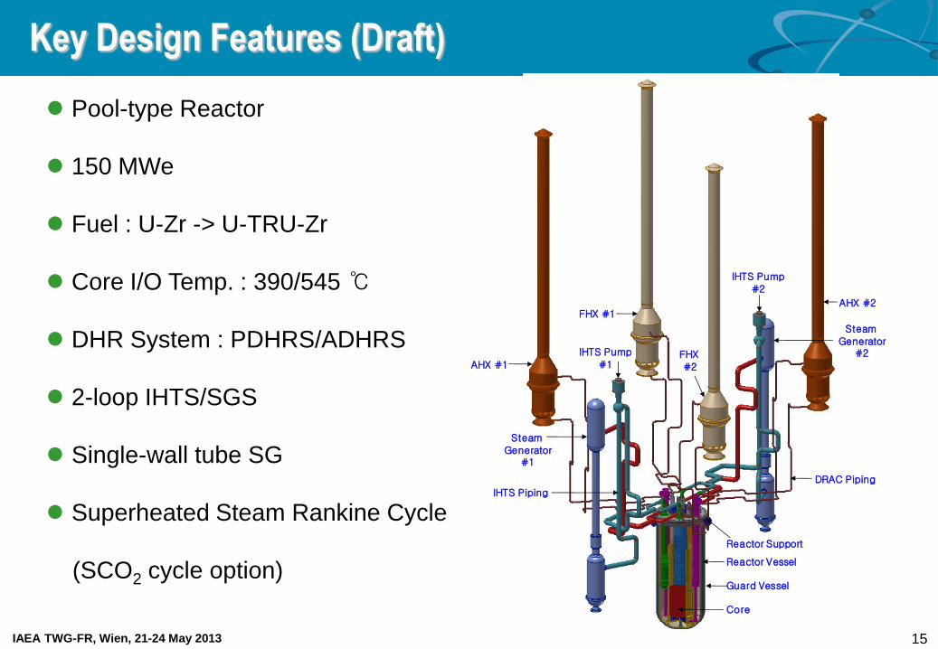
Pool-type Reactor
150 MWe
Fuel : U-Zr -> U-TRU-Zr
Core I/O Temp. : 390/545 ℃
DHR System : PDHRS/ADHRS
2-loop IHTS/SGS
Single-wall tube SG
Superheated Steam Rankine Cycle
(SCO2 cycle option)
Key Design Features (Draft)
AHX #1
AHX #2FHX #1
FHX #2
Steam
Generator#1
Steam Generator
#2
DRAC Piping
IHTS Piping
Guard Vessel
IHTS Pump#1
IHTS Pump#2
Reactor Vessel
Core
Reactor Support

IAEA TWG-FR, Wien, 21-24 May 2013 16
Conceptual Design-Core Design
Core Configuration of 150MWe Prototype SFR
Trade-off Study – 50/75/100/125/150/200/600 MWe
– Two Concerns to Power Level
Economy: Smaller Fuel inventory
TRU Fuel Irradiation Capability: Higher
Fast Neutron Flux
Prototype SFR Core – Power Level: 150 MWe
– Initial Core : Uranium Metal Fueled Core
Test and Demonstrate TRU Fuel
– will evolve into TRU Core
Determination of Power Level
Inner Core
Secondary control rod
Primary control rod
Reflector
B4C shield
IVS
Radial shield
33
7
3
102
60
138
78
Outer Core 90

IAEA TWG-FR, Wien, 21-24 May 2013 17
Core U LTRU MTRU
EFPD / # of Batches [day / #] 290 / 5 290 / 5 290 / 5
# of Fuel Assembly (IC/OC) 33/90 33/90 33/66
Fuel Pin Diameter [cm] 0.74 0.74 0.70
P/D Ratio 1.125 1.125 1.189
Active Core Height [cm] 100.0 100.0 100.0
Lower Shield Height 90.0 90.0 90.0
Fission Gas Plenum Height[cm] 150.0 150.0 150.0
Enrichment (IC/OC) [w/o] 14.0 / 19.5 14.9 / 21.8 20.2/29.6
Fuel Loading Amount [Ton/GWe] 107.9 107.8 76.4
Charged Amount [kg] Heavy Metal 2205 2204 1576
TRU 0 438 415
MA 0 40 51
Fissile 397 237 195
Reactivity Swing [pcm] 1184 695 1493
Burnup [MWD/kg] Average 50.2 50.4 70.5
Peak 78.7 81.8 110.1
Fast N. Flux [x1015 n/cm2·sec] Average 0.98 1.18 1.41
Peak 1.54 1.87 2.22
Peek Fast N. Fluence [x1023 n/cm2] 1.95 / 1.93 2.37 / 2.36 2.83 / 2.71
Linear Power Density [W/cm] Average 104.7 105.1 129.7
Peak 180.0 178.6 219.7
Pressure Drop [MPa] 0.255 0.255 0.204
Cladding Midwall Temp. [oC] 645 645 645
Core Function
Core Design
Core Configuration
U / LTRU core MTRU core
<Core Performance>

IAEA TWG-FR, Wien, 21-24 May 2013 18
Fluid System Design
Key Design Features
System Concept
System Heat Balance
System design concept from trade-off study
to enhance plant safety and to improve economic &
performance
PHTS – Pool-type
– Two PHTS pumps
– Four IHXs
IHTS – Two loops
– Two straight tube steam generators
– Two mechanical pumps on cold legs
– Passive protection of IHX from SG tube failure by cold
leg piping layout
DHRS: Passive (PDHRS) / Active (ADHRS)
Energy conversion system
– Superheated steam Rankine cycle

IAEA TWG-FR, Wien, 21-24 May 2013 19
Loop Cover gas High
Low
Relief valve
SodiumAHX
DHX
Reactor head
Hot-leg
Cold-leg
Expansion
vessel
Plane A
Plane B
Plane C
x
y
z
Rx.
Support
wall
4.05 m *
9.65 m
4.15 m
2.5 m
6.65 m 7.65 m
2.5 m2.5 m
7.71 m
2.5 m
3.5 m
2.5 m
4.2 m
1.0 m
1.34 m
3.58 m
16.4
1 m
15.4
1 m
36.0 m
4.45 m
~ 2
5.1
2 m
22.7
m
1.7
55
m
3.0
8 m
2.0
3 m
1.54 m
2.18 m
2.18 m 4.2 m
Hot-leg (48.07 m)
- Vertical length : 19.99 m
- Horizontal length : 28.08 m
- Coaxial part : 5.79 m
Cold-leg (40.99 m)
- Vertical length : 15.91 m
- Horizontal length : 25.08 m
- Coaxial part : 6.79 m
2.5 m
1.85 m
2.85 m
1.0
5 m
( 10 inch SCH40 )
( 10 inch SCH40 ) 1.0
5 m
*: Distance from DHX center
0.5 m
Loop Cover gas High
Low
Relief valve
Sodium
DHX
Reactor head
Hot-leg
Cold-leg
Expansion
vessel
Plane A
Plane B
Plane C
x
y
z
Rx.
Support
wall
4.05 m *
9.65 m
4.15 m
2.5 m
6.65 m 7.65 m
2.5 m2.5 m
7.71 m
2.5 m
3.5 m
1.0 m
1.34 m
3.58 m
16.4
1 m
15.4
1 m
39.0 m
4.45 m
24.6
8 m
22.7
m
1.7
55
m
2.0
3 m
1.10 m
Hot-leg (48.07 m)
- Vertical length : 19.99 m
- Horizontal length : 28.08 m
- Coaxial part : 5.79 m
Cold-leg (40.99 m)
- Vertical length : 15.91 m
- Horizontal length : 25.08 m
- Coaxial part : 6.79 m
2.5 m
1.85 m
2.85 m
1.0
5 m
( 10 inch SCH40 )
( 10 inch SCH40 ) 1.0
5 m
*: Distance from DHX center
0.26 m
FHX
2.5 m
6.38 m
3.3
2 m
6.38 m
1.50 m
EM
P
Decay Heat Removal System
Safety-grade DHR system
– Ultimate heat sink for DBA
PDHRS (Passive Decay Heat Removal System)
– Two independent heat removal loops
– DHX, AHX, Expansion tank, Air dampers
– Use of natural circulation of Sodium & Air
– Operation
Emergency heat rejection w/o operators’ action
ADHRS (Active Decay Heat Removal System)
– Two independent heat removal loops
– DHX, FHX, Expansion tank, EMP, Air blower, Air dampers
– Use of forced (and/or natural) circulation of Sodium & Air
– Operation
Scheduled & Emergency operation
50% heat removal capacity for SBO condition
PDHRS loop configuration ADHRS loop configuration
DHX AHX FHX

IAEA TWG-FR, Wien, 21-24 May 2013 20
Mechanical Structure Design
Core
Primary Pump
IHX
Steam Generator
AHX
FHX
DHXUpper Internal Structure
Double Vessel
- Reactor Vessel
- Containment Vessel
Main Design Features
- Simple reactor enclosure system
Uniform vessel thickness
No penetrations and no attachment on
vessel
- Double vessels (Reactor and Guard vessels)
- Skirt type core support structure excluding weld
joint with reactor vessel
- Significantly reduced IHTS piping length using
9Cr-1Mo-V steel
- Seismic Isolation Design for Reactor Island (Rx
Bldg, Aux Bldg and Wastage/Maintenance Bldg)
. – ASME BVP III division 5 is applied to high
temperature design
Key Design Features

IAEA TWG-FR, Wien, 21-24 May 2013 21
Evaluation of its safety functions of the PGSFR on DBEs
MARS-LMR Nodalization
Safety Evaluation of the PGSFR
1 10 100 1000 10000
300
350
400
450
500
550
600
650
700
750
DHRS heat removal ~ power
Reactor trip
Reactor Vessel Leak
initiation
Reactor Vessel Leak
Core inlet temperature
Core outlet temperature
Co
ola
nt T
em
pe
ratu
re,
oC
Time, s
16.3
17.2168
1.1
CORE
180175
178170
130135
160165
16.8
17.658
InletPlenum
18.486
0.0
1.26
2.0
Upper Hot Pool
0.3
Hot PoolRiser
7.896
10.946
137
150
145MP
140
Buffer
265,275285,295
260,270280,290
0.6096
Buffer
120
115MP
110
100
105
200
235
107
215
205 210
220
225
230
237
IHX
240
300,350
pipe
310,360
pipe
390,395
sngljun320,370
pipe
345
pipe
380
pump
385
pipe
0.3
5.2
245242
250247
DHX
5.3
5.554
7.055
7.1557.4455
11.733
10310.946
12.257
185190
195
11.257
11.84
6.326.9
7.0
315,365
branch
11.307 11.307
10.0
1.755
237
240
6.801
345
pipe
385
pipe
SG
325,375
sngljun333
sngljun
335
pipe
338
sngljun
340
pipe
28m
610
625
615 825
613
617
620
835
820
AHX
Reactor Vessel Leak Transient of Over Power
Safety evaluation of the PGSFR
- Representative transients of TOP, LOF, LOHS,
Primary pipe break, reactor vessel break have been
evaluated with the MARS-LMR code.
- PGSFR design satisfied the safety criteria with an
appropriate margin.
ATWS transients of UTOP, ULOF, ULOHS have
been evaluated with the MARS-LMR code.
The 6 sub-channel flow blockage was also
evaluated and ensured to satisfy the safety limits.
The performance of the DHRS during typical DBE
and BDBE has been checked to show that the
DHRS design has ability to prevent the fuel rod
heat-up due to inherent natural circulation function.
Further work
- Safety analysis for final conceptual design will be
followed. Typical Temperatures

IAEA TWG-FR, Wien, 21-24 May 2013 22
R&D Activities IV

IAEA TWG-FR, Wien, 21-24 May 2013 23
STELLA Program
STELLA (Sodium Test Loop for Safety Simulation and Assessment)
– Phase 1: STELLA-1
• Performance evaluation of key sodium components
• Heat exchanger design codes V&V
– Phase 2: STELLA-2
• Verification of dynamic plant response after reactor shutdown
• Construction of test DB to support specific design approval for the prototype SFR
Schedule

IAEA TWG-FR, Wien, 21-24 May 2013 24
Overall Characteristics of STELLA-1
Main test loop
– Test components
• Sodium-to-sodium heat exchanger (DHX)
• Sodium-to-air heat exchanger (AHX)
• Mechanical sodium pump (PHTS pump)
– Electrical loop heaters, EM pumps, Flow meters,
Expansion tanks, Sodium storage tank
Sodium purification system
– Cold trap, Plugging meter, etc.
Auxiliary Systems
– Gas supply & Vacuum system
– Power supply system
– Fire protection system
Working fluid Liquid sodium Total electric power 2.5 MW
Total sodium inventory ~ 18 ton Heat capacity of HXs 1.0MW
Design temperature 600oC Design pressure 10 bar
Max. flowrate for HX test 10 kg/s Max. flowrate for Pump test 125 kg/s
STELLA-1 Layout
Overall Size (W×L×H): 15m×8m×22m
Main Characteristics

IAEA TWG-FR, Wien, 21-24 May 2013 25
Tube-side (Na)
Shell-side (Air)
Forced Circulation Flow (kg/s)
3.5 3.9 10.0
Forced-draft
Flow (kg/s)
3.5 ○ ○ ○
5.0 ○ ○ ○
Natural-draft N/A ○ ○ ○
Test Scope & Conditions
Tube-side (Na)
Shell-side (Na)
Forced Circulation Flow (kg/s)
3.5 3.9 10.0
Forced
Circulation
Flow (kg/s)
3.6 ○ ○ ○
5.3 ○ ○ ○
10.0 ○ ○ ○
< Matrix for DHX performance test >
AHX Shell-side
DHX Shell-side
Forced-draft Flow (kg/s) Natural-
draft 3.5 5.0
Forced
Circulation
Flow (kg/s)
3.6 ○ ○ ○
5.3 ○ ○ ○
10.0 ○ ○ ○
(Air)
(Na)
< Matrix for AHX performance test >
< Matrix for DHX-AHX natural circulation test >
DHX performance test
- Nominal & Transient conditions by flowrate change
Function of sodium Peclet number
- Heat transfer & Pressure drop characteristics
AHX performance test
- Nominal & Transient conditions by flowrate change
Function of air Reynolds number
- Heat transfer & Pressure drop characteristics
DHX-AHX natural circulation test
- DHX shell-side sodium: Forced circulation
- AHX shell-side air: Forced- & Natural-draft
- Natural circulation flowrate inside loop piping
Mechanical sodium pump test
- Sodium temperature: ~350oC
- Constitution of test matrix
N/NR : 25 ~ 100% (every 10%)
(Q/QR) : 5 ~ 125% (every 5%)

IAEA TWG-FR, Wien, 21-24 May 2013 26
S-CO2 Brayton Cycle
Development of S-CO2 Brayton cycle Integral Experiment Loop (SCIEL)
Objectives
- Develop the S-CO2 Brayton Cycle Integral Experiment
Loop(SCIEL) and verify the characteristics of the S-CO2
recompression cycle and operation technologies
• SCIEL: 550oC-20MPa turbine inlet temperature, heat
input 730kW, net power generation 200kWe
SCIEL Schedule
- 2013: Installation starting of SCIEL
• Step I: Compressor Performance Test Loop (‘13.June)
• Step II: Simple Cycle Test Loop
• Step III: Simple Recuperated Cycle Test Loop
- 2014: Completion of SCIEL operation test
• Step IV: Recompression Cycle Test Loop
Schematics and major specification of the SCIEL

IAEA TWG-FR, Wien, 21-24 May 2013 27
Development of under-sodium ultrasonic waveguide sensor module and
Performance tests in sodium
C-Scan test of waveguide sensor in sodium R&D Contents
- Development of under-sodium ultrasonic waveguide sensor
• Be and Ni coating for the well-developed beam profile
generation in sodium
- Performance tests of under-sodium waveguide sensor
modules in sodium
• Ultrasonic wave propagation and sensitivity test in sodium
• C-scan imaging resolution test
- Design and construction of sodium wetting test facility
• Sodium wetting test chamber
Operation in high temperature condition (up to 350 ℃)
Sodium test tank, sodium storage tank, enclosure box
Ar purging system
• Steel enclosure structure for the protection of sodium fire
accident for the long duration operation
t
Under-Sodium Test
Test Target 2 mm C-Scan Image
Sodium wetting test facility with enclosure structure
Ultrasonic Transient Signal (10 m)
Ultrasonic Waveguide Sensor for Under-sodium Viewing

IAEA TWG-FR, Wien, 21-24 May 2013 28
Tube fabrication process - Intermediate heat treatment effects
Increase of hardness in modified fabrication process
- Final heat treatment effects
Increase of UTS and YS in modified fabrication process
Heat treatment process - Evaluation of intermediate heat treatment conditions
IHT temperature : 700oC & 720oC
IHT time : 10, 30, 60min
Selection of IHT conditions for cold working process
- Evaluation of final heat treatment conditions
Normalizing temperature : 950 ~ 1100oC
Tempering temperature : 700 ~ 800oC
Selection of candidate FHT conditions
Development cladding tube fabrication process
Fuel Cladding Development
Hardness change with IHT Tensile properties with FHT
Tensile strength with FHT Mechanical property diagram
M.T
1st drawing
2nd 3rd
4th 5th
M.T
2nd 3rd
4th
1st drawing
Normalized at 1050oC for 30min 650oC tension test
UTS of AR HT9
YS of AR HT9
+12.3%
+16.3%
Hardness change with drawing
UTS change with FHT

IAEA TWG-FR, Wien, 21-24 May 2013 29
Fuel Fabrication and Performance Evaluation
Fuel casting technology and Fuel irradiation test in HANARO
Fuel irradiation test in HANARO - Irradiation of U-Zr-(Ce) fuel up to 3 at%
- Completion of Irradiation
•2010.11.15~2012.1.5
-Nondestructive Test
•γ- scanning : 12 rodlets completion
-Destructive Test
•Fission gas release measurement : 3 rodlets
•Microstructure by OM, SEM etc
Lower fuel rodlet
Upper fuel rodlet
Coolant
Fuel slug
Hf tube
A-AB-B Neutral plane of core
Bottom view
Fuel slug casting - Modification of casting process and equipment:
melting and casting temperature, preheating
temperature of melt distributer, and melting batch
size
- Modification results
• Fuel dimensions: Φ5-L300 mm
• Deviation of Zr content and fuel density:
0.1~0.2wt%, 0.1~0.2g/cm3
• Feeding rate of melt to mold: 95%
• Fuel loss: 0.1%
U-10Zr fuel slugs
Gamma radiography

IAEA TWG-FR, Wien, 21-24 May 2013 30
Development of Codes and Verification
Reactor Physics Experiments
- Collaboration with IPPE (Institute for Physics and Power Engineering) is going on.
- Three critical assemblies were constructed :
BFS-73-1, BFS-75-1
BFS-76-1A for TRU burner concept (without blanket, deep insertion of CR at BOEC)
- Representative Experiment for Prototype SFR
BFS-109-2A : high enriched uranium fuel (U-10Zr)
Thermal-Hydraulic Validation Test
- Three test activities are planned
Validation tests of reactor core thermal-hydraulic characteristics: Test DB is established and
Conceptual facility design has been developed
performance tests of the finned-tube sodium-to-air heat exchanger (FHX): Concept of finned
tube heat exchanger has been developed for verification of FHX thermal sizing.
V&V of steam generator design code: to be conducted untill 2016

IAEA TWG-FR, Wien, 21-24 May 2013 31
Numerical codes were developed to estimate energy release and core
expansion behavior in the case of CDA
Scoping analysis of Severe Accident
Analysis of energy release from CDA
- Energy release from CDA was estimated for
KALIMER-150 core using CDA-ER code
based on the Bethe-Tait methods
- The influences of Doppler effect on the power
excursion were estimated, and the obtained
results were used as initial conditions for core
expansion analysis
Analysis of core expansion behavior
- Numerical code was developed to investigate
core expansion behavior during the power
excursion of KALIMER-150 core
- The transient behaviors of a vaporized core
expansion and its effects on coolant were
analyzed through numerical computations
He
core
sodium
18m
7.4m
0
200
400
600
800
0.000 0.005 0.010 0.015
rad
ial ve
locity
(m/s
)
time (s)
(b) Core expansion velocity (c) Computation domain
0
2
4
6
8
10
12
14
3.0 3.5 4.0 4.5
time (msec)
E (GJ)
Power (TW)
Pressure (GPa)
(a) Released energy from CDA

IAEA TWG-FR, Wien, 21-24 May 2013 32
Summary
Long-term Advanced SFR Development Plan was revised by KAEC
in November 2011
– Specific design by 2017
– Specific design approval by 2020
– Construction of a prototype SFR by 2028
Activities for development of an Advanced SFR include
– Conceptual core design from U core to MTRU core
– Conceptual design of fluid system & mechanical structure
– Development of metal fuel
– Under sodium viewing for in-service inspection
– STELLA for major components test and integral effect test including decay heat
removal system
– Reactor physics experiment for U-Zr core
– Evaluation of representative DBEs and BDBEs using MARS-LMR code
Overall System Design for Prototype SFR is started this year


