
Brookville, OH USA Phone 937-833-4033 www.norgren.com ACT-2-1
Series SS 1-1/2" thru 8" Cylinder Features ...........................................ACT-2-2Ultra Cushion & Soft Touch Bumper Seal ............................................ACT-2-3Technical Information............................................................................ACT-2-4 Cylinder with 01 (MX0) Basic................................................................ACT-2-6Cylinder with 02 (MS4) Bottom Tap .....................................................ACT-2-8Cylinder with 04 (MF1) Front Flange .................................................ACT-2-10Cylinder with 05 (MF2) Rear Flange ..................................................ACT-2-12Cylinder with 06 (MP1) Cap Fixed Clevis ...........................................ACT-2-148" Cylinder with 10 (ME3) Head Square & 11 (ME4) Cap Square ....ACT-2-16Cylinder with 15 (MT1) Head Trunnion ..............................................ACT-2-18Cylinder with 16 (MT2) Cap Trunnion.................................................ACT-2-20Double Rod End Cylinder with 01 (MX0) Basic .................................ACT-2-221-1/2" thru 8" Cylinder Accessories ....................................................ACT-2-24Optional Features & Custom Cylinders...............................................ACT-2-251-1/2" thru 8" Order Information..........................................................ACT-2-26
Series SS 1-1/8" Cylinder Features ......................................................ACT-2-271-1/8" Cylinder with 01 (MX0) Basic, 03 (MS8) Bolt Thru,
04 (MF7) Front Flange, 05 (MF2) Rear Flange ............................ACT-2-281-1/8" Cylinder with 17 (MP3) Fixed Eye, 22 (MS9) Side Tap,
30 (MR1) Head Face ....................................................................ACT-2-301-1/8" Double Rod End Cylinder with 01 (MX0) Basic .......................ACT-2-301-1/8" Cylinder Accessories & Optional Features...............................ACT-2-321-1/8" Order Information .....................................................................ACT-2-33
Switch Information .................................................................................ACT-2-34
ACT-2-6 –Cylinder with01 (MX0) Basic
ACT-2-8 –Cylinder with02 (MS4)Bottom Tap
ACT-2-10 –Cylinder with04 (MF1) Front Flange
ACT-2-12 –Cylinder with05 (MF2) Rear Flange
ACT-2-14 –Cylinder with06 (MP1) Cap Fixed Clevis
ACT-2-16 –8" Cylinder with10 (ME3) Head Square
ACT-2-16 –8" Cylinder with11 (ME4)Cap Square
ACT-2-18 –Cylinder with15 (MT1)Head Trunnion
ACT-2-20 –Cylinder with16 (MT2) Cap Trunnion
ACT-2-22 –Double Rod EndCylinder with01 (MX0) Basic
ACT-2-28 –1-1/8" Cylinder with 01 (MX0)Basic
ACT-2-28 –1-1/8" Cylinder with 03 (MS8) Bolt Thru
ACT-2-28 –1-1/8" Cylinder with 04 (MF7) Front Flange
ACT-2-28 –1-1/8" Cylinder with 05 (MF2) Rear Flange
ACT-2-30 –1-1/8" Cylinder with 17 (MP3) Fixed Eye
ACT-2-30 –1-1/8" Cylinder with 22 (MS9) Side Tap
ACT-2-30 –1-1/8" Cylinder with 30 (MR1) Head Face
ACT-2-30 –1-1/8" Double RodEnd Cylinder with 01 (MX0) Basic
Section 2
Series SSStainless Steel Cylinders

ACT-2-2 Brookville, OH USA Phone 937-833-4033 www.norgren.com
Series SS Actuators
Tube: Corrosion-resistant 304stainless steel.10
The finest materials for each component!Piston: Solid aluminum alloy,
light-weight for low inertia, yet strong.
Head/Cap: Precision machined from solid corrosion-resistant 304 stainless steel bar.
Piston Seals: Lip-type nitrile sealsare pressure energized and wearcompensating. Their excellent lubricationretention characteristics lower seal frictionand ensure long life.
Rod Seals: Rounded lip-type urethane ispressure energized and wear compensating.
Piston Rod: 303 stainless steel,40,000 PSI minimum yield, hard chromeplated, ground and polished.
Rod Wiper: Lip-type urethaneaggressively wipes foreign material frompiston rod and enhances rod seal life.
1
4
5
63
2
Wear Strip: Teflon® and graphitecomposition for minimum friction,maximum wear and side load resistance.(Magnetic band under wear strip optional.)
Ultra Cushion®: State-of-the-artdesign features a unique, one-piece, nitrilecompound seal, captured within a precisionmachined groove. Linear and radial “float”of cushion seal eliminates misalignment.Ultra Cushions provide exceptionally fast“out of cushion” stroke reversal. (Head andCap Cushions are optional.)
Tie Rods: High-strength 303 stainless steel maintains compression on tube end seals.
Rod Bearings: Machined from 304stainless steel, with a Teflon® composite wear band insert that eliminates metal-to-metal contact.
Retainer: Stainless steel snap ringsecurely retains bushing in head.
Acorn Nut: Tie rod threads arecovered by stainless steel acorn nuts whicheliminate another bacteria hiding place.
7
9
11
12
14
13
Adjustable Captive CushionNeedle
Allows for safe and precise adjustment under pressure.
8
54
6
Series DSeries D cylinders are designed for extremely smooth stroke performance on applications requiring very slow extensionand/or retraction speeds. They are identical to the Series SS in design, function and dimensions, but have “ELF” carboxylatednitrile piston seals, rod seals, and rod wipers.“ELF” carboxylated nitrile is a blend of Teflon® and other low friction additives that are molded into the substrate of the base seal material.Incorporating this compound in the dynamic seals of the cylinder results in diminished friction, lower breakaway and superior stroke performance.
Features:• Extra smooth performance throughout the entire stroke of the cylinder. • NFPA interchangeable.• Available in standard SS series bore sizes. • Cylinders rated to 250 PSI air.
83 1
1 2 3
13
14
12
8
711
1097

Brookville, OH USA Phone 937-833-4033 www.norgren.com ACT-2-3
Series SS Actuators
Norgren’s state-of-the-art cushion design features a unique,one-piece, nitrile compound seal that is captured within aprecision machined groove. This allows both linear and radial “float” of the cushion seal which virtually eliminatesproblems associated with misalignment. Integral flow pathsmolded in the periphery of the seal provide exceptionally fast “out of cushion” stroke reversal without the use of ball checks.
Ultra Cushion®
A Major Design and Performance Breakthrough in Air Cylinder Cushioning Systems!
Soft Touch Bumper SealThe solution for noise pollution!
Norgren’s Low Friction Soft Touch Bumper Seal, in conjunction with our state-of-the-art cushion design, decelerates and reduces end-of-stroke noise.
Figure 1: Cylinder deceleration starts when the cushion spear enters the cushion seal, creating a chamber ofcompressed air metered by an optional Adjustable Cushion Needle or Fixed Cushion (orifice).
Figure 2: The final inertia load is absorbed by the Bumper, providing that final end-of-stroke “Soft Touch”.
See ACT-2-26 for complete instructions on how to order cylinders.
Operating PSI will control the reduction of total cylinder stroke. The chart shows the approximate average (new cylinder) stroke reductions in inches based on PSI.
Stroke length will vary based on PSI.
Not recommended for applications that require 100% repeatable stroke increment.
Available on 1-1/8" thru 5" bores.(Not available in 1-1/2" bore with 1" diameter rod.)
Can be incorporated into cylinders with no cushions, fixed cushions or adjustable cushions.
Figure 2 shows spear exiting cushion seal.
Figure 1
Bore 0 PSI 20 PSI 40 PSI 60 PSI 80 PSI 100 PSI1 1/8 " .12 .08 .06 .03 .02 01 1/2 " .12 .04 .03 .02 .01 02" .12 .10 .06 .03 .02 02 1/2 " .16 .10 .08 .04 .02 03 1/4" .18 .10 .08 .04 .02 04 " .20 .14 .10 .06 .02 05" .22 .14 .10 .06 .02 0
Figure 1 Figure 2
Note: 11/8" bore configuration.
11/2"_5" bore

ACT-2-4 Brookville, OH USA Phone 937-833-4033 www.norgren.com
Series SS ActuatorsAll Dimensions in Inches (mm)
Listed are the average breakaway pressuresin PSI for all Series SS and Series D cylinderbore sizes. If your application requires a lowerbreakaway pressure than indicated for aparticular bore size, consult the factory.
Operating Temperatures:Series SS -40°F to 200°F
(-40°C to 93°C)Series D -20°F to 250°F
(-29°C to 121°C)with Viton Seals -20°F to 400°F
(-29°C to 204°C)
Operating Pressure:250 PSIG Air (17.2 Bar)400 PSIG Hydraulic (27.6 Bar)Bore Sizes: 1-1/8", 1-1/2", 2", 2-1/2", 3-1/4",4", 5", 6", 8"
Supply:Filtered compressed air to 250 PSIPetroleum based hydraulic fluid to 400 PSI
Lubrication:None requiredNorgren Air Cylinders are rated for “no lube added”service. All internal components are lubricated at timeof assembly with a Teflon® based grease.
Materials:Head and End Caps: 304 stainless steelTube: 304 stainless steelPiston Rod: hard chrome plated 303 stainless steelPiston: 2011-T451 aluminum with Teflon®
composite wearbandRod Bearings: 304 stainless steel with Teflon®
composite wearbandSeals: urethane rod seal and wiper, nitrile piston sealsTie Rods: 303 stainless steel
Side Loading:Cylinders are specifically designed to push and pull.Side loading of the piston rod should be avoided toensure maximum operating performance and life.Care should be taken during installation to properly align the load to be moved with the centerline of the cylinder. The use of a rod alignment coupler(see ACT-2-24) is strongly recommended wheneverpossible.
Bore SS Series D SeriesExtend Retract Extend Retract
11/8" 6 7 3 411/2", 2", 21/2" 5 6 3 431/4", 4" 4 5 2 35", 6", 8" 3 4 1 2
Breakaway Pressures in PSI
Note: Breakaway pressures were established with the cylinders mounted horizontallyand no load on the piston rod.
Cylinder Weights In pounds (kilograms)
*Weight includes pivot pin
Mounting CodeBore Rod Add Per Inch
01, 02, 03, 10, 11, 22 & 30 04 & 05 *06 & 17 15 & 16 of Stroke3/8" (9.53) 1.1 (.49) 1.5 (.68) 1.3 (.58) – – .13 (.05)
11/8" (28.58)1/2" (12.70) 1.2 (.54) 1.6 (.72) 1.4 (.63) – – .15 (.06)5/8" (15.88) 3.3 (1.49) 4.0 (1.81) 3.8 (1.72) 3.8 (1.72) .3 (.13)
11/2" (38.10)1" (25.40) 4.1 (1.85) 4.8 (2.17) 4.6 (2.08) 4.6 (2.08) .4 (.18)5/8" (15.88) 5.9 (2.67) 7.0 (3.17) 6.4 (2.90) 6.4 (2.90) .5 (.22)
2" (50.80)1" (25.40) 6.3 (2.85) 7.4 (3.35) 6.8 (2.94) 6.8 (3.08) .6 (.27)5/8" (15.88) 8.0 (3.62) 9.5 (4.30) 8.7 (3.94) 8.5 (3.85) .6 (.27)
21/2" (63.50)1" (25.40) 8.5 (3.85) 10.0 (4.53) 9.2 (4.17) 9.0 (4.08) .7 (.31)1" (25.40) 15.0 (6.80) 18.7 (8.48) 16.0 (7.25) 15.5 (7.03) .8 (.36)
31/4" (82.55)13/8" (34.93) 15.5 (7.03) 19.2 (8.70) 16.5 (7.48) 16.0 (7.25) 1.0 (.45)1" (25.40) 23.0 (10.43) 28.0 (12.70) 27.0 (12.24) 23.5 (10.65) 1.0 (.45)
4" (101.60)13/8" (34.93) 23.5 (10.65) 28.5 (12.92) 27.5 (12.47) 24.0 (10.88) 1.2 (.54)1" (25.40) 34.5 (15.64) 42.0 (19.05) 41.0 (18.59) 35.0 (15.87) 1.1 (.49)
5" (127.00)13/8" (34.93) 35.0 (15.87) 42.5 (19.27) 41.5 (18.82) 35.5 (16.10) 1.3 (.58)13/8" (34.93) 60.0 (27.21) 71.9 (32.61) 69.0 (31.29) 61.2 (27.76) 1.5 (.68)
6" (152.40)13/4" (44.45) 62.0 (28.12) 73.9 (33.52) 71.0 (32.20) 63.2 (28.66) 1.7 (.77)13/8" (34.93) 79.0 (35.83) – – 88.0 (39.91) 80.2 (36.37) 2.0 (.90)
8" (203.20)13/4" (44.45) 82.0 (37.19) – – 91.0 (41.27) 83.2 (37.73) 2.3 (1.04)

Brookville, OH USA Phone 937-833-4033 www.norgren.com ACT-2-5
Series SS ActuatorsAll Dimensions in Inches (mm)
(.72) (20) (30) (40) (50) (75) (100) (2)(1.26) (35) (52) (70) (87) (131) (174) (3)(1.98) (53) (80) (111) (138) (205) (271) (5)(5.06) (138) (209) (280) (351) (525) (698) (13)(9.58) (262) (396) (529) (663) (997) (1321) (24)
(15.51) (423) (641) (854) (1068) (1601) (2135) (39)
.112 5 7 9 11 17 22 .00007
.196 8 12 16 20 30 39 .00011
.307 12 18 25 31 46 61 .00018
.785 31 47 63 70 118 157 .000451.485 59 89 119 149 222 297 .000862.404 95 144 192 240 360 480 .00139
VolumeCu Ft (cm3)
Rod Rod PSI (bar) Displacement Area 40 (3) 60 (4) 80 (6) 100 (7) 150 (10) 200 (14) Per Inch
3/8"1/2"5/8"1"13/8"13/4"
(6.41) (177) (265) (354) (442) (664) (890) (16)(11.40) (315) (472) (629) (786) (1179) (1570) (29)(20.27) (559) (839) (1119) (1398) (2097) (2793) (52)(31.67) (874) (1311) (1748) (2185) (3277) (4368) (80)(53.32) (1477) (2215) (2953) (3692) (5538) (7379) (136)(81.07) (2237) (3355) (4473) (5592) (8388) (11178) (206)
(126.71) (3491) (5240) (6988) (8736) (13104) (17472) (322)(182.39) (5026) (7544) (10061) (12574) (18860) (25149) (520)(324.26) (8940) (13411) (17881) (22356) (33533) (44711) (631)
.99 40 60 80 99 149 200 .00057 1.77 71 106 142 177 266 353 .001023.14 126 189 251 314 471 628 .001824.91 196 295 393 491 737 982 .002848.30 332 498 664 830 1245 1659 .00480
12.57 503 754 1005 1257 1886 2513 .0072719.64 785 1178 1571 1964 2946 3928 .0113728.27 1130 1696 2262 2827 4240 5654 .0183750.26 2010 3015 4020 5026 7539 10052 .02227
VolumeCu Ft (cm3)
Bore Piston PSI (bar) DisplacementArea 40 (3) 60 (4) 80 (6) 100 (7) 150 (10) 200 (14) Per Inch
11/8"11/2"2"21/2"31/4"4"5"6"8"
Deduct these Forces for Retract Strokes
Piston Rod Diameter Selection:Applications requiring long extend (push) strokes may require oversize piston rod diameters to prevent buckling. To determine the correct rod diameter for yourapplication follow these simple steps:1. Select the thrust from the Cylinder Force and Volume Chart that is required for your application.
Thrust = Piston Surface Area x Operating Pressure2. From the Cylinder Mounting Diagrams select the mounting style being used.3. With the piston rod fully extended, calculate the value of D (in inches) using the formula shown or the cylinder mounting diagram selected in step #2.4. Locate the value of D (in inches) at the bottom of the Selection Chart. Enter the chart at this point and move vertically upward until intersecting with the horizontal
line representing the required thrust which was selected in step #1. The band within which these lines intersect represents the minimum recommended piston rod diameter.
Stop Tube Selection:Stop tubes enhance the transverse load carrying capability of a long stroke cylinder by increasing the distance between the piston and rod bearing at full extension. Whenthe value of D (calculated from the piston rod diameter selection instructions above) is less than 40", a stop tube is not required. However, if D is 40" or more, 1" of stoptube is recommended for every 10" (or fraction thereof) over 40".
Cylinder Mounting Diagrams
Value of D in inches
Axial thrust in lbs
200
1-3/4"
1-3/8" 1" 5/8"
150 100 50 0506070
100
200
300400500
800
600
1000
2000
3000
400050006000
800010000
5000040000
30000
20000
80
Selection ChartCylinder Force and Volume ChartsExtend Forces in pounds (newtons)
Firmly Guided Rod End Head Trunnion Unsupported Rod End Supported Rod End
Supported Rod End Firmly Guided Rod End Unsupported Rod End Cap Clevis or Cap Trunnion
D
D=D
d
dS S
S S
DS
S
D=4S D=S
D=4S
D=DD=1/2S
D=S D=1/2S
ACT-2-6 Brookville, OH USA Phone 937-833-4033 www.norgren.com
Series SS Actuators
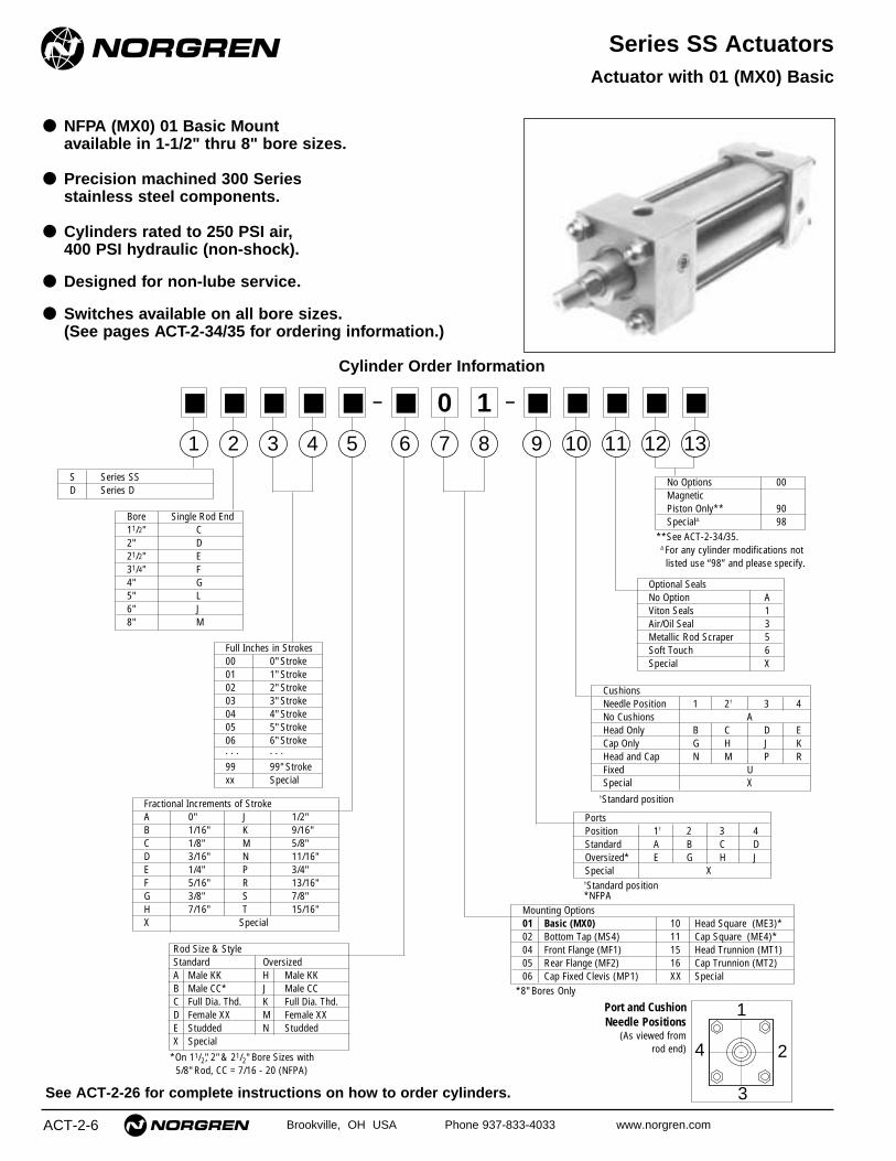
● NFPA (MX0) 01 Basic Mountavailable in 1-1/2" thru 8" bore sizes.
● Precision machined 300 Series stainless steel components.
● Cylinders rated to 250 PSI air,400 PSI hydraulic (non-shock).
● Designed for non-lube service.
● Switches available on all bore sizes.(See pages ACT-2-34/35 for ordering information.)
Actuator with 01 (MX0) Basic
Cylinder Order Information
See ACT-2-26 for complete instructions on how to order cylinders.
PortsPosition 1† 2 3 4Standard A B C DOversized* E G H JSpecial X
Mounting Options01 Basic (MX0) 10 Head Square (ME3)*02 Bottom Tap (MS4) 11 Cap Square (ME4)*04 Front Flange (MF1) 15 Head Trunnion (MT1)05 Rear Flange (MF2) 16 Cap Trunnion (MT2)06 Cap Fixed Clevis (MP1) XX Special
Rod Size & StyleStandard OversizedA Male KK H Male KKB Male CC* J Male CCC Full Dia. Thd. K Full Dia. Thd.D Female XX M Female XXE Studded N StuddedX Special
Fractional Increments of StrokeA 0" J 1/2"B 1/16" K 9/16"C 1/8" M 5/8"D 3/16" N 11/16"E 1/4" P 3/4"F 5/16" R 13/16"G 3/8" S 7/8"H 7/16" T 15/16"X Special
Full Inches in Strokes00 0" Stroke01 1" Stroke02 2" Stroke03 3" Stroke04 4" Stroke05 5" Stroke06 6" Stroke. . . . . .
99 99" Strokexx Special
S Series SSD Series D
No Options 00Magnetic Piston Only** 90Special∆ 98
1
■
2
■
3
■
4
■
5
■
6
■
8
110
■
13
■
12
■
11
■
9
■
7
0– –
Optional SealsNo Option AViton Seals 1Air/Oil Seal 3Metallic Rod Scraper 5Soft Touch 6Special X
**See ACT-2-34/35.∆ For any cylinder modifications not listed use “98” and please specify.
†Standard position*NFPA
1
4 2
3
Port and CushionNeedle Positions
(As viewed from rod end)
Bore Single Rod End11/2" C2" D21/2" E31/4" F4" G5" L6" J8" M
*On 11/2", 2" & 21/2" Bore Sizes with5/8" Rod, CC = 7/16 - 20 (NFPA)
*8" Bores Only
CushionsNeedle Position 1 2† 3 4 No Cushions AHead Only B C D ECap Only G H J KHead and Cap N M P RFixed USpecial X
†Standard position

(15.88) (15.88) (15.88) (25.40) (25.40) (25.40) (34.93) (34.93)(25.40) (25.40) (25.40) (34.93) (34.93) (34.93) (44.45) (44.45)(19.05) (19.05) (19.05) (28.58) (28.58) (28.58) (41.28) (41.28)(28.58) (28.58) (28.58) (41.28) (41.28) (41.28) (50.80) (50.80)(28.58) (28.58) (28.58) (38.10) (38.10) (38.10) (50.80) (50.80)(38.10) (38.10) (38.10) (50.80) (50.80) (50.80) (60.33) (60.33)
(9.53) (9.53) (9.53) (12.70) (12.70) (12.70) (15.88) (15.88)(12.70) (12.70) (12.70) (15.88) (15.88) (15.88) (19.05) (19.05)
(12.70) (12.70) (12.70) (20.62) (20.62) (20.62) (28.58) (28.58)(20.62) (20.62) (20.62) (28.58) (28.58) (28.58) (38.10) (38.10)(50.80) (63.50) (76.20) (95.25) (114.30) (139.70) (165.10) (215.90)(6.35) (6.35) (6.35) (9.53) (9.53) (9.53) (12.70) (12.70)(9.53) (9.53) (9.53) (12.70) (12.70) (12.70) (19.05) (19.05)
(38.10) (38.10) (38.10) (44.45) (44.45) (44.45) (50.80) (50.80)(25.40) (25.40) (25.40) (31.75) (31.75) (38.10) (38.10) (38.1)(11.91) (13.49) (13.49) (15.88) (15.88) (21.08) (21.08) (25.40)
(92.08) (92.08) (95.25) (107.95) (107.95) (114.30) (127.00) (130.18)(53.98) (53.98) (57.15) (66.68) (66.68) (73.03) (76.20) (79.38)(36.32) (46.74) (55.63) (70.10) (84.33) (104.14) (123.95) (163.45)(15.88) (15.88) (15.88) (22.23) (22.23) (22.23) (25.40) (25.40)(22.23) (22.23) (22.23) (25.40) (25.40) (25.40) (28.58) (28.58)
(50.80) (50.80) (50.80) (61.90) (61.90) (61.90) (73.03) (73.03)(60.33) (60.33) (60.33) (68.25) (68.25) (68.25) (79.38) (79.38)
(129.39) (130.96) (134.14) (158.75) (158.75) (170.31) (189.36) (196.85)(138.91) (140.49) (143.66) (165.10) (165.10) (176.66) (195.71) (203.20)
Dimension 11/2" Bore (38.10) 2" Bore (50.80) 21/2" Bore (63.50) 31/4" Bore (82.55) 4" Bore (101.60) 5" Bore (127.00) 6" Bore (152.40) 8" Bore (203.20)
ø Rod Std.(MM) O.S.
A Std.O.S.
B Std.O.S.
CStd.O.S.
CCStd. 7/16 – 20 7/16 – 20 7/16 – 20 7/8 –14 7/8 –14 7/8 –14 11/4 – 12 11/4 – 12O.S. 7/8 –14 7/8 –14 7/8 –14 11/4 – 12 11/4 – 12 11/4 – 12 11/2 – 12 11/2 – 12
DStd.O.S.
E
EEStd.O.S.
FFStd. 5/8 –18 5/8 –18 5/8 –18 1 –14 1 –14 1 –14 13/8 – 12 13/8 – 12O.S. 1 –14 1 –14 1 –14 13/8 – 12 13/8 – 12 13/8 – 12 13/4 – 12 13/4 – 12
GJK
KK Std. 1/2 – 20 1/2 – 20 1/2 – 20 3/4 – 16 3/4 – 16 3/4 – 16 1 – 14 1 – 14O.S. 3/4 – 16 3/4 – 16 3/4 – 16 1 – 14 1 – 14 1 – 14 11/4 – 12 11/4 – 12
LBPRE
VFStd.O.S.
XXStd. 7/16 – 20 7/16 – 20 7/16 – 20 3/4 – 16 3/4 – 16 3/4 – 16 1 – 14 1 – 14O.S. 3/4 – 16 3/4 – 16 3/4 – 16 1 – 14 1 – 14 1 – 14 11/4 – 12 11/4 – 12
Y Std.O.S.
ZBStd.O.S.
.5/8" .5/8" .5/8" .1" .1" .1" 1.3/8" 1.3/8"
.1" .1" .1" 1.3/8" 1.3/8" 1.3/8" 1.3/4" 1.3/4"
.750 .750 .750 1.125 1.125 1.125 1.625 1.6251.125 1.125 1.125 1.625 1.625 1.625 2.000 2.0001.125 1.125 1.125 1.500 1.500 1.500 2.000 2.0001.500 1.500 1.500 2.000 2.000 2.000 2.375 2.375.375 .375 .375 .500 .500 .500 .625 .625.500 .500 .500 .625 .625 .625 .750 .750
.500 .500 .500 .812 .812 .812 1.125 1.125
.812 .812 .812 1.125 1.125 1.125 1.500 1.5002.000 2.500 3.000 3.750 4.500 5.500 6.500 8.500.250 .250 .250 .375 .375 .375 .500 .500.375 .375 .375 .500 .500 .500 .750 .750
1.500 1.500 1.500 1.750 1.750 1.750 2.000 2.0001.000 1.000 1.000 1.250 1.250 1.500 1.500 1.500.469 .531 .531 .625 .625 .830 .830 1.000
3.625 3.625 3.750 4.250 4.250 4.500 5.000 5.1252.125 2.125 2.250 2.625 2.625 2.875 3.000 3.1251.430 1.840 2.190 2.760 3.320 4.100 4.880 6.435.625 .625 .625 .875 .875 .875 1.000 1.000.875 .875 .875 1.000 1.000 1.000 1.125 1.125
2.000 2.000 2.000 2.437 2.437 2.437 2.875 2.8752.375 2.375 2.375 2.687 2.687 2.687 3.125 3.1255.094 5.156 5.281 6.250 6.250 6.705 7.455 7.7505.469 5.531 5.656 6.500 6.500 6.955 7.705 8.000
Brookville, OH USA Phone 937-833-4033 www.norgren.com ACT-2-7
Series SS ActuatorsAll Dimensions in Inches (mm)
Standard& Optional Rod Ends
KJ
LB + Stroke
ZB + Stroke
G
VF
C
A
KK Thds.
∅ MM
∅ B Bushing P + StrokeY
Across FlatsD
REESq.
EE NPT (2)
Y
∅ B ∅ B ∅ B ∅ BCCThds. XX
Thds.
A Deep
FFThds.
XXThds.
VF VF VF VF
A A A
Style #2 (Optional Male)
Style #3 (Small Female)
Style #4(Optional Full Diameter Threads)
Style #5 (Optional Studded)
CCCC
KK Thds.
DAcrossFlats
VF
A
∅ B
Style #1(Small Male)
C

ACT-2-8 Brookville, OH USA Phone 937-833-4033 www.norgren.com
Series SS Actuators
● NFPA (MS4) 02 Bottom Tap Mount available in 1-1/2" thru 8" bore sizes.
● Precision machined 300 Series stainless steel components.
● Cylinders rated to 250 PSI air,400 PSI hydraulic (non-shock).
● Designed for non-lube service.
● Switches available on all bore sizes.(See pages ACT-2-34/35 for ordering information.)
Actuator with 02 (MS4) Bottom Tap
Cylinder Order Information
See ACT-2-26 for complete instructions on how to order cylinders.
Rod Size & StyleStandard OversizedA Male KK H Male KKB Male CC* J Male CCC Full Dia. Thd. K Full Dia. Thd.D Female XX M Female XXE Studded N StuddedX Special
Fractional Increments of StrokeA 0" J 1/2"B 1/16" K 9/16"C 1/8" M 5/8"D 3/16" N 11/16"E 1/4" P 3/4"F 5/16" R 13/16"G 3/8" S 7/8"H 7/16" T 15/16"X Special
Full Inches in Strokes00 0" Stroke01 1" Stroke02 2" Stroke03 3" Stroke04 4" Stroke05 5" Stroke06 6" Stroke. . . . . .
99 99" Strokexx Special
S Series SSD Series D
1
■
2
■
3
■
4
■
5
■
6
■
8
210
■
13
■
12
■
11
■
9
■
7
0– –
*On 11/2", 2" & 21/2" Bore Sizes with5/8" Rod, CC = 7/16 - 20 (NFPA)
PortsPosition 1† 2 3 4Standard A B C DOversized* E G H JSpecial X
Mounting Options01 Basic (MX0) 10 Head Square (ME3)*02 Bottom Tap (MS4) 11 Cap Square (ME4)*04 Front Flange (MF1) 15 Head Trunnion (MT1)05 Rear Flange (MF2) 16 Cap Trunnion (MT2)06 Cap Fixed Clevis (MP1) XX Special
No Options 00Magnetic Piston Only** 90Special∆ 98
**See ACT-2-34/35.∆ For any cylinder modifications not listed use “98” and please specify.
†Standard position*NFPA
1
4 2
3
Port and CushionNeedle Positions
(As viewed from rod end)
*8" Bores Only
CushionsNeedle Position 1 2† 3 4 No Cushions AHead Only B C D ECap Only G H J KHead and Cap N M P RFixed USpecial X
†Standard position
Optional SealsNo Option AViton Seals 1Air/Oil Seal 3Metallic Rod Scraper 5Soft Touch 6Special X
Bore Single Rod End11/2" C2" D21/2" E31/4" F4" G5" L6" J8" M

(15.88) (15.88) (15.88) (25.40) (25.40) (25.40) (34.93) (34.93)(25.40) (25.40) (25.40) (34.93) (34.93) (34.93) (44.45) (44.45)(19.05) (19.05) (19.05) (28.58) (28.58) (28.58) (41.28) (41.28)(28.58) (28.58) (28.58) (41.28) (41.28) (41.28) (50.80) (50.80)(28.58) (28.58) (28.58) (38.10) (38.10) (38.10) (50.80) (50.80)(38.10) (38.10) (38.10) (50.80) (50.80) (50.80) (60.33) (60.33)(9.53) (9.53) (9.53) (12.70) (12.70) (12.70) (15.88) (15.88)
(12.70) (12.70) (12.70) (15.88) (15.88) (15.88) (19.05) (19.05)
(12.70) (12.70) (12.70) (20.62) (20.62) (20.62) (28.58) (28.58)(20.62) (20.62) (20.62) (28.58) (28.58) (28.58) (38.10) (38.10)(50.80) (63.50) (76.20) (95.25) (114.30) (139.70) (165.10) (215.90)(6.35) (6.35) (6.35) (9.53) (9.53) (9.53) (12.70) (12.70)(9.53) (9.53) (9.53) (12.70) (12.70) (12.70) (19.05) (19.05)
(38.10) (38.10) (38.10) (44.45) (44.45) (44.45) (50.80) (50.80)(25.40) (25.40) (25.40) (31.75) (31.75) (38.10) (38.10) (38.1)(11.91) (13.49) (13.49) (15.88) (15.88) (21.08) (21.08) (25.40)
(92.08) (92.08) (95.25) (107.95) (107.95) (114.30) (127.00) (130.18)
(53.98) (53.98) (57.15) (66.68) (66.68) (73.03) (76.20) (79.38)(36.32) (46.74) (55.63) (70.10) (84.33) (104.14) (123.95) (163.45)(57.15) (57.15) (60.33) (66.68) (66.68) (73.03) (79.38) (82.55)(9.53) (12.70) (15.88) (19.05) (19.05) (25.40) (28.58) (28.58)
(15.88) (22.23) (31.75) (38.10) (52.37) (68.25) (82.55) (114.30)(15.88) (15.88) (15.88) (22.23) (22.23) (22.23) (25.40) (25.40)(22.23) (22.23) (22.23) (25.40) (25.40) (25.40) (28.58) (28.58)(49.20) (49.20) (49.20) (61.90) (61.90) (61.90) (71.42) (71.42)(58.72) (58.72) (58.72) (68.25) (68.25) (68.25) (77.77) (77.77)
(50.80) (50.80) (50.80) (61.90) (61.90) (61.90) (73.03) (73.03)(60.33) (60.33) (60.33) (68.25) (68.25) (68.25) (79.38) (79.38)
(129.39) (130.96) (134.14) (158.75) (158.75) (170.31) (189.36) (196.85)(138.91) (140.49) (143.66) (165.10) (165.10) (176.66) (195.71) (203.20)
Dimension 11/2" Bore (38.10) 2" Bore (50.80) 21/2" Bore (63.50) 31/4" Bore (82.55) 4" Bore (101.60) 5" Bore (127.00) 6" Bore (152.40) 8" Bore (203.20)
ø Rod Std.(MM) O.S.
AStd.O.S.
B Std.O.S.
CStd.O.S.
CCStd. 7/16 – 20 7/16 – 20 7/16 – 20 7/8 –14 7/8 –14 7/8 –14 11/4 – 12 11/4 – 12O.S. 7/8 –14 7/8 –14 7/8 –14 11/4 – 12 11/4 – 12 11/4 – 12 11/2 – 12 11/2 – 12
DStd.O.S.
E
EEStd.O.S.
FFStd. 5/8 –18 5/8 –18 5/8 –18 1 –14 1 –14 1 –14 13/8 – 12 13/8 – 12O.S. 1 –14 1 –14 1 –14 13/8 – 12 13/8 – 12 13/8 – 12 13/4 – 12 13/4 – 12
GJK
KK Std. 1/2 – 20 1/2 – 20 1/2 – 20 3/4 – 16 3/4 – 16 3/4 – 16 1 – 14 1 – 14O.S. 3/4 – 16 3/4 – 16 3/4 – 16 1 – 14 1 – 14 1 – 14 11/4 – 12 11/4 – 12
LBNT 1/4 – 20 5/16 – 18 3/8 – 16 1/2 – 13 1/2 – 13 5/8 – 11 3/4 – 10 3/4 – 10PRESNTKTN
VFStd.O.S.
XTStd.O.S.
XXStd. 7/16 – 20 7/16 – 20 7/16 – 20 3/4 – 16 3/4 – 16 3/4 – 16 1 – 14 1 – 14O.S. 3/4 – 16 3/4 – 16 3/4 – 16 1 – 14 1 – 14 1 – 14 11/4 – 12 11/4 – 12
Y Std.O.S.
ZBStd.O.S.
.5/8" .5/8" .5/8" .1" .1" .1" 1.3/8" 1.3/8"
.1" .1" .1" 1.3/8" 1.3/8" 1.3/8" 1.3/4" 1.3/4"
.750 .750 .750 1.125 1.125 1.125 1.625 1.6251.125 1.125 1.125 1.625 1.625 1.625 2.000 2.0001.125 1.125 1.125 1.500 1.500 1.500 2.000 2.0001.500 1.500 1.500 2.000 2.000 2.000 2.375 2.375.375 .375 .375 .500 .500 .500 .625 .625.500 .500 .500 .625 .625 .625 .750 .750
.500 .500 .500 .812 .812 .812 1.125 1.125
.812 .812 .812 1.125 1.125 1.125 1.500 1.5002.000 2.500 3.000 3.750 4.500 5.500 6.500 8.500.250 .250 .250 .375 .375 .375 .500 .500.375 .375 .375 .500 .500 .500 .750 .750
1.500 1.500 1.500 1.750 1.750 1.750 2.000 2.0001.000 1.000 1.000 1.250 1.250 1.500 1.500 1.500.469 .531 .531 .625 .625 .830 .830 1.000
3.625 3.625 3.750 4.250 4.250 4.500 5.000 5.125
2.125 2.125 2.250 2.625 2.625 2.875 3.000 3.1251.430 1.840 2.190 2.760 3.320 4.100 4.880 6.4352.250 2.250 2.375 2.625 2.625 2.875 3.125 3.250.375 .500 .625 .750 .750 1.000 1.125 1.125.625 .875 1.250 1.500 2.062 2.687 3.250 4.500.625 .625 .625 .875 .875 .875 1.000 1.000.875 .875 .875 1.000 1.000 1.000 1.125 1.125
1.937 1.937 1.937 2.437 2.437 2.437 2.812 2.8122.312 2.312 2.312 2.687 2.687 2.687 3.062 3.062
2.000 2.000 2.000 2.437 2.437 2.437 2.875 2.8752.375 2.375 2.375 2.687 2.687 2.687 3.125 3.1255.094 5.156 5.281 6.250 6.250 6.705 7.455 7.7505.469 5.531 5.656 6.500 6.500 6.955 7.705 8.000
Brookville, OH USA Phone 937-833-4033 www.norgren.com ACT-2-9
Series SS ActuatorsAll Dimensions in Inches (mm)
EE NPT (2)
(Flats)D
TNRE
KK Thds.
Y
NT TapTK Deep
XT
A
C G
VF
J K
∅ B Bushing
∅ MM
P + Stroke
SN + Stroke
LB + Stroke
ZB + Stroke
ESq.
Standard & Optional Rod Ends
KK Thds.
DAcrossFlats
VF
A
∅ B
Style #1(Small Male)
C
∅ B ∅ B ∅ B ∅ BCCThds. XX
Thds.
A Deep
FFThds.
XXThds.
VF VF VF VF
A A A
Style #2 (Optional Male)
Style #3 (Small Female)
Style #4(Optional Full Diameter Threads)
Style #5 (Optional Studded)
CCCC
ACT-2-10 Brookville, OH USA Phone 937-833-4033 www.norgren.com
Series SS Actuators
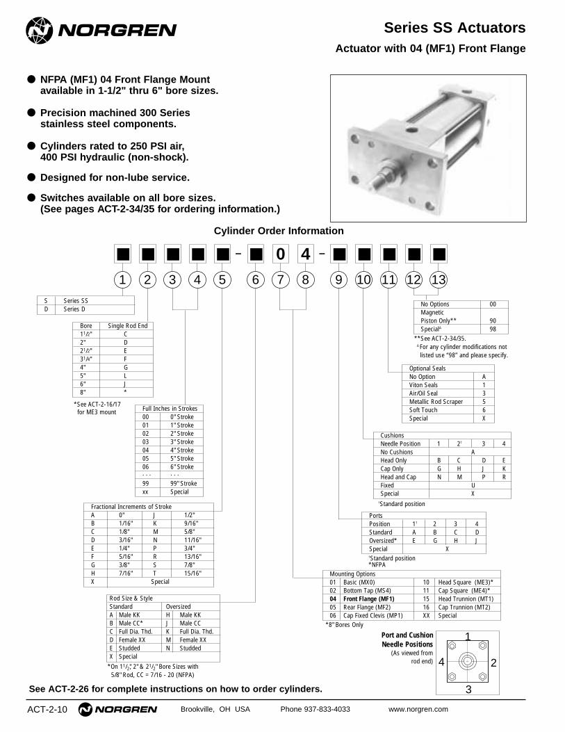
● NFPA (MF1) 04 Front Flange Mount available in 1-1/2" thru 6" bore sizes.
● Precision machined 300 Series stainless steel components.
● Cylinders rated to 250 PSI air,400 PSI hydraulic (non-shock).
● Designed for non-lube service.
● Switches available on all bore sizes.(See pages ACT-2-34/35 for ordering information.)
Actuator with 04 (MF1) Front Flange
Cylinder Order Information
See ACT-2-26 for complete instructions on how to order cylinders.
Rod Size & StyleStandard OversizedA Male KK H Male KKB Male CC* J Male CCC Full Dia. Thd. K Full Dia. Thd.D Female XX M Female XXE Studded N StuddedX Special
Fractional Increments of StrokeA 0" J 1/2"B 1/16" K 9/16"C 1/8" M 5/8"D 3/16" N 11/16"E 1/4" P 3/4"F 5/16" R 13/16"G 3/8" S 7/8"H 7/16" T 15/16"X Special
Full Inches in Strokes00 0" Stroke01 1" Stroke02 2" Stroke03 3" Stroke04 4" Stroke05 5" Stroke06 6" Stroke. . . . . .
99 99" Strokexx Special
S Series SSD Series D
1
■
2
■
3
■
4
■
5
■
6
■
8
410
■
13
■
12
■
11
■
9
■
7
0– –
*On 11/2", 2" & 21/2" Bore Sizes with5/8" Rod, CC = 7/16 - 20 (NFPA)
*See ACT-2-16/17 for ME3 mount
PortsPosition 1† 2 3 4Standard A B C DOversized* E G H JSpecial X
Mounting Options01 Basic (MX0) 10 Head Square (ME3)*02 Bottom Tap (MS4) 11 Cap Square (ME4)*04 Front Flange (MF1) 15 Head Trunnion (MT1)05 Rear Flange (MF2) 16 Cap Trunnion (MT2)06 Cap Fixed Clevis (MP1) XX Special
No Options 00Magnetic Piston Only** 90Special∆ 98
**See ACT-2-34/35.∆ For any cylinder modifications not listed use “98” and please specify.
†Standard position*NFPA
1
4 2
3
Port and CushionNeedle Positions
(As viewed from rod end)
*8" Bores Only
CushionsNeedle Position 1 2† 3 4 No Cushions AHead Only B C D ECap Only G H J KHead and Cap N M P RFixed USpecial X
†Standard position
Optional SealsNo Option AViton Seals 1Air/Oil Seal 3Metallic Rod Scraper 5Soft Touch 6Special X
Bore Single Rod End11/2" C2" D21/2" E31/4" F4" G5" L6" J8" *

(15.88) (15.88) (15.88) (25.40) (25.40) (25.40) (34.93)(25.40) (25.40) (25.40) (34.93) (34.93) (34.93) (44.45)(19.05) (19.05) (19.05) (28.58) (28.58) (28.58) (41.28) (41.28)(28.58) (28.58) (28.58) (41.28) (41.28) (41.28) (50.80) (50.80)(28.58) (28.58) (28.58) (38.10) (38.10) (38.10) (50.80) (50.80)(38.10) (38.10) (38.10) (50.80) (50.80) (50.80) (60.33) (60.33)(9.53) (9.53) (9.53) (12.70) (12.70) (12.70) (15.88) (15.88)
(12.70) (12.70) (12.70) (15.88) (15.88) (15.88) (19.05) (19.05)
(12.70) (12.70) (12.70) (20.62) (20.62) (20.62) (28.58) (28.58)(20.62) (20.62) (20.62) (28.58) (28.58) (28.58) (38.10) (38.10)(50.80) (63.50) (76.20) (95.25) (114.30) (139.70) (165.10) (215.90)(6.35) (6.35) (6.35) (9.53) (9.53) (9.53) (12.70) (12.70)(9.53) (9.53) (9.53) (12.70) (12.70) (12.70) (19.05) (19.05)(7.92) (9.53) (9.53) (11.10) (11.10) (14.27) (14.27) (17.45)
(9.53) (9.53) (9.53) (15.88) (15.88) (15.88) (19.05)(38.10) (38.10) (38.10) (44.45) (44.45) (44.45) (50.80) (50.80)(25.40) (25.40) (25.40) (31.75) (31.75) (38.10) (38.10) (44.45)(11.91) (13.49) (13.49) (15.88) (15.88) (21.08) (21.08) (25.40)
(92.08) (92.08) (95.25) (107.95) (107.95) (114.30) (127.00) (130.18)(53.98) (53.98) (57.15) (66.68) (66.68) (73.03) (76.20) (79.38)(36.32) (46.74) (55.63) (70.10) (84.33) (104.14) (123.95) (192.28)(69.85) (85.73) (98.43) (119.08) (138.10) (168.28) (193.68)(85.73) (104.78) (117.48) (139.70) (158.75) (193.68) (219.08)(15.88) (15.88) (15.88) (22.23) (22.23) (22.23) (25.40) (25.40)(22.23) (22.23) (22.23) (25.40) (25.40) (25.40) (28.58) (28.58)(15.88) (15.88) (15.88) (19.05) (19.05) (19.05) (22.23) (41.28)(25.40) (25.40) (25.40) (25.40) (25.40) (25.40) (28.58) (47.63)
(50.80) (50.80) (50.80) (61.90) (61.90) (61.90) (73.03) (73.03)(60.33) (60.33) (60.33) (68.25) (68.25) (68.25) (79.38) (79.38)
(129.39) (130.96) (134.14) (158.75) (158.75) (170.31) (189.36) (196.85)(138.91) (140.49) (143.66) (165.10) (165.10) (176.66) (195.71) (203.20)
.5/8" .5/8" .5/8" .1" .1" .1" 1.3/8"
.1" .1" .1" 1.3/8" 1.3/8" 1.3/8" 1.3/4"
.750 .750 .750 1.125 1.125 1.125 1.625 1.6251.125 1.125 1.125 1.625 1.625 1.625 2.000 2.0001.125 1.125 1.125 1.500 1.500 1.500 2.000 2.0001.500 1.500 1.500 2.000 2.000 2.000 2.375 2.375.375 .375 .375 .500 .500 .500 .625 .625.500 .500 .500 .625 .625 .625 .750 .750
.500 .500 .500 .812 .812 .812 1.125 1.125
.812 .812 .812 1.125 1.125 1.125 1.500 1.5002.000 2.500 3.000 3.750 4.500 5.500 6.500 8.500.250 .250 .250 .375 .375 .375 .500 .500.375 .375 .375 .500 .500 .500 .750 .750.312 .375 .375 .437 .437 .562 .562 .687
.375 .375 .375 .625 .625 .625 .7501.500 1.500 1.500 1.750 1.750 1.750 2.000 2.0001.000 1.000 1.000 1.250 1.250 1.500 1.500 1.750.469 .531 .531 .625 .625 .830 .830 1.000
3.625 3.625 3.750 4.250 4.250 4.500 5.000 5.1252.125 2.125 2.250 2.625 2.625 2.875 3.000 3.1251.430 1.840 2.190 2.760 3.320 4.100 4.880 7.5702.750 3.375 3.875 4.687 5.437 6.625 7.6253.375 4.125 4.625 5.500 6.250 7.625 8.625.625 .625 .625 .875 .875 .875 1.000 1.000.875 .875 .875 1.000 1.000 1.000 1.125 1.125.625 .625 .625 .750 .750 .750 .875 1.625
1.000 1.000 1.000 1.000 1.000 1.000 1.125 1.875
2.000 2.000 2.000 2.437 2.437 2.437 2.875 2.8752.375 2.375 2.375 2.687 2.687 2.687 3.125 3.1255.094 5.156 5.281 6.250 6.250 6.705 7.455 7.7505.469 5.531 5.656 6.500 6.500 6.955 7.705 8.000
Dimension 11/2" Bore (38.10) 2" Bore (50.80) 21/2" Bore (63.50) 31/4" Bore (82.55) 4" Bore (101.60) 5" Bore (127.00) 6" Bore (152.40) 8" Bore (203.20)
ø Rod Std.(MM) O.S.
A Std.O.S.
B Std.O.S.
CStd.O.S.
CCStd. 7/16 – 20 7/16 – 20 7/16 – 20 7/8 –14 7/8 –14 7/8 –14 11/4 – 12 11/4 – 12O.S. 7/8 –14 7/8 –14 7/8 –14 11/4 – 12 11/4 – 12 11/4 – 12 11/2 – 12 11/2 – 12
DStd.O.S.
E
EEStd.O.S.
FB
FFStd. 5/8 –18 5/8 –18 5/8 –18 1 –14 1 –14 1 –14 13/8 – 12 13/8 – 12O.S. 1 –14 1 –14 1 –14 13/8 – 12 13/8 – 12 13/8 – 12 13/4 – 12 13/4 – 12
FH –GJK
KK Std. 1/2 – 20 1/2 – 20 1/2 – 20 3/4 – 16 3/4 – 16 3/4 – 16 1 – 14 1 – 14O.S. 3/4 – 16 3/4 – 16 3/4 – 16 1 – 14 1 – 14 1 – 14 11/4 – 12 11/2 – 12
LBPRTF –UF –
VFStd.O.S.
WStd.O.S.
XXStd. 7/16 – 20 7/16 – 20 7/16 – 20 3/4 – 16 3/4 – 16 3/4 – 16 1 – 14 1 – 14O.S. 3/4 – 16 3/4 – 16 3/4 – 16 1 – 14 1 – 14 1 – 14 11/4 – 12 11/4 – 12
Y Std.O.S.
ZBStd.O.S.
Brookville, OH USA Phone 937-833-4033 www.norgren.com ACT-2-11
Series SS ActuatorsAll Dimensions in Inches (mm)
KJ
LB + Stroke
ZB + Stroke
VF
G
Y P + Stroke
FHW
C
A
KK Thds.
DAcross Flats
TF
UF
RE
EE NPT (2)∅ B Bushing
∅ MM
FB
Standard & Optional Rod Ends
KK Thds.
DAcrossFlats
VF
A
∅ B
Style #1(Small Male)
C
∅ B ∅ B ∅ B ∅ BCCThds. XX
Thds.
A Deep
FFThds.
XXThds.
VF VF VF VF
A A A
Style #2 (Optional Male)
Style #3 (Small Female)
Style #4(Optional Full Diameter Threads)
Style #5 (Optional Studded)
CCCC

ACT-2-12 Brookville, OH USA Phone 937-833-4033 www.norgren.com
Series SS Actuators
● NFPA (MF2) 05 Rear Flange Mount available in 1-1/2" thru 6" bore sizes.
● Precision machined 300 Series stainless steel components.
● Cylinders rated to 250 PSI air,400 PSI hydraulic (non-shock).
● Designed for non-lube service.
● Switches available on all bore sizes.(See pages ACT-2-34/35 for ordering information.)
Actuator with 05 (MF2) Rear Flange
Cylinder Order Information
See ACT-2-26 for complete instructions on how to order cylinders.
Rod Size & StyleStandard OversizedA Male KK H Male KKB Male CC* J Male CCC Full Dia. Thd. K Full Dia. Thd.D Female XX M Female XXE Studded N StuddedX Special
Fractional Increments of StrokeA 0" J 1/2"B 1/16" K 9/16"C 1/8" M 5/8"D 3/16" N 11/16"E 1/4" P 3/4"F 5/16" R 13/16"G 3/8" S 7/8"H 7/16" T 15/16"X Special
Full Inches in Strokes00 0" Stroke01 1" Stroke02 2" Stroke03 3" Stroke04 4" Stroke05 5" Stroke06 6" Stroke. . . . . .
99 99" Strokexx Special
S Series SSD Series D
1
■
2
■
3
■
4
■
5
■
6
■
8
510
■
13
■
12
■
11
■
9
■
7
0– –
*On 11/2", 2" & 21/2" Bore Sizes with5/8" Rod, CC = 7/16 - 20 (NFPA)
*See ACT-2-16/17 for ME3 mount
PortsPosition 1† 2 3 4Standard A B C DOversized* E G H JSpecial X
Mounting Options01 Basic (MX0) 10 Head Square (ME3)*02 Bottom Tap (MS4) 11 Cap Square (ME4)*04 Front Flange (MF1) 15 Head Trunnion (MT1)05 Rear Flange (MF2) 16 Cap Trunnion (MT2)06 Cap Fixed Clevis (MP1) XX Special
No Options 00Magnetic Piston Only** 90Special∆ 98
**See ACT-2-34/35.∆ For any cylinder modifications not listed use “98” and please specify.
†Standard position*NFPA
1
4 2
3
Port and CushionNeedle Positions
(As viewed from rod end)
*8" Bores Only
CushionsNeedle Position 1 2† 3 4 No Cushions AHead Only B C D ECap Only G H J KHead and Cap N M P RFixed USpecial X
†Standard position
Optional SealsNo Option AViton Seals 1Air/Oil Seal 3Metallic Rod Scraper 5Soft Touch 6Special X
Bore Single Rod End11/2" C2" D21/2" E31/4" F4" G5" L6" J8" *

(15.88) (15.88) (15.88) (25.40) (25.40) (25.40) (34.93)(25.40) (25.40) (25.40) (34.93) (34.93) (34.93) (44.45)(19.05) (19.05) (19.05) (28.58) (28.58) (28.58) (41.28) (41.28)(28.58) (28.58) (28.58) (41.28) (41.28) (41.28) (50.80) (50.80)(28.58) (28.58) (28.58) (38.10) (38.10) (38.10) (50.80) (50.80)(38.10) (38.10) (38.10) (50.80) (50.80) (50.80) (60.33) (60.33)(9.53) (9.53) (9.53) (12.70) (12.70) (12.70) (15.88) (15.88)
(12.70) (12.70) (12.70) (15.88) (15.88) (15.88) (19.05) (19.05)
(12.70) (12.70) (12.70) (20.62) (20.62) (20.62) (28.58) (28.58)(20.62) (20.62) (20.62) (28.58) (28.58) (28.58) (38.10) (38.10)(50.80) (63.50) (76.20) (95.25) (114.30) (139.70) (165.10) (215.90)(6.35) (6.35) (6.35) (9.53) (9.53) (9.53) (12.70) (12.70)(9.53) (9.53) (9.53) (12.70) (12.70) (12.70) (19.05) (19.05)(7.92) (9.53) (9.53) (11.10) (11.10) (14.27) (14.27) (17.45)
(9.53) (9.53) (9.53) (15.88) (15.88) (15.88) (19.05)(38.10) (38.10) (38.10) (44.45) (44.45) (44.45) (50.80) (50.80)(25.40) (25.40) (25.40) (31.75) (31.75) (38.10) (38.10) (44.45)
(92.08) (92.08) (95.25) (107.95) (107.95) (114.30) (127.00) (130.18)(53.98) (53.98) (57.15) (66.68) (66.68) (73.03) (76.20) (79.38)(36.32) (46.74) (55.63) (70.10) (84.33) (104.14) (123.95) (192.28)(69.85) (85.73) (98.43) (119.08) (138.10) (168.28) (193.68)(85.73) (104.78) (117.48) (139.70) (158.75) (193.68) (219.08)(15.88) (15.88) (15.88) (22.23) (22.23) (22.23) (25.40) (25.40)(22.23) (22.23) (22.23) (25.40) (25.40) (25.40) (28.58) (28.58)
(50.80) (50.80) (50.80) (61.90) (61.90) (61.90) (73.03) (73.03)(60.33) (60.33) (60.33) (68.25) (68.25) (68.25) (79.38) (79.38)
(127.00) (127.00) (130.18) (158.75) (158.75) (165.10) (187.33) (171.68)(136.53) (136.53) (139.70) (165.10) (165.10) (171.45) (193.68) (177.80)
.5/8" .5/8" .5/8" .1" .1" .1" 1.3/8"
.1" .1" .1" 1.3/8" 1.3/8" 1.3/8" 1.3/4"
.750 .750 .750 1.125 1.125 1.125 1.625 1.6251.125 1.125 1.125 1.625 1.625 1.625 2.000 2.0001.125 1.125 1.125 1.500 1.500 1.500 2.000 2.0001.500 1.500 1.500 2.000 2.000 2.000 2.375 2.375.375 .375 .375 .500 .500 .500 .625 .625.500 .500 .500 .625 .625 .625 .750 .750
.500 .500 .500 .812 .812 .812 1.125 1.125
.812 .812 .812 1.125 1.125 1.125 1.500 1.5002.000 2.500 3.000 3.750 4.500 5.500 6.500 8.500.250 .250 .250 .375 .375 .375 .500 .500.375 .375 .375 .500 .500 .500 .750 .750.312 .375 .375 .437 .437 .562 .562 .687
.375 .375 .375 .625 .625 .625 .7501.500 1.500 1.500 1.750 1.750 1.750 2.000 2.0001.000 1.000 1.000 1.250 1.250 1.500 1.500 1.750
3.625 3.625 3.750 4.250 4.250 4.500 5.000 5.125. 2.125 2.125 2.250 2.625 2.625 2.875 3.000 3.125
1.430 1.840 2.190 2.760 3.320 4.100 4.880 7.5702.750 3.375 3.875 4.687 5.437 6.625 7.6253.375 4.125 4.625 5.500 6.250 7.625 8.625.625 .625 .625 .875 .875 .875 1.000 1.000.875 .875 .875 1.000 1.000 1.000 1.125 1.125
2.000 2.000 2.000 2.437 2.437 2.437 2.875 2.8752.375 2.375 2.375 2.687 2.687 2.687 3.125 3.1255.000 5.000 5.125 6.250 6.250 6.500 7.375 6.7505.375 5.375 5.500 6.500 6.500 6.750 7.625 7.000
Dimension 11/2" Bore (38.10) 2" Bore (50.80) 21/2" Bore (63.50) 31/4" Bore (82.55) 4" Bore (101.60) 5" Bore (127.00) 6" Bore (152.40) 8" Bore (203.20)
ø Rod Std.(MM) O.S.
A Std.O.S.
B Std.O.S.
CStd.O.S.
CCStd. 7/16 – 20 7/16 – 20 7/16 – 20 7/8 –14 7/8 –14 7/8 –14 11/4 – 12 11/4 – 12O.S. 7/8 –14 7/8 –14 7/8 –14 11/4 – 12 11/4 – 12 11/4 – 12 11/2 – 12 11/2 – 12
DStd.O.S.
E
EEStd.O.S.
FB
FFStd. 5/8 –18 5/8 –18 5/8 –18 1 –14 1 –14 1 –14 13/8 – 12 13/8 – 12O.S. 1 –14 1 –14 1 –14 13/8 – 12 13/8 – 12 13/8 – 12 13/4 – 12 13/4 – 12
FH –GJ
KK Std. 1/2 – 20 1/2 – 20 1/2 – 20 3/4 – 16 3/4 – 16 3/4 – 16 1 – 14 1 – 14O.S. 3/4 – 16 3/4 – 16 3/4 – 16 1 – 14 1 – 14 1 – 14 11/4 – 12 11/2 – 12
LBPRTF –UF –
VFStd.O.S.
XXStd. 7/16 – 20 7/16 – 20 7/16 – 20 3/4 – 16 3/4 – 16 3/4 – 16 1 – 14 1 – 14O.S. 3/4 – 16 3/4 – 16 3/4 – 16 1 – 14 1 – 14 1 – 14 11/4 – 12 11/4 – 12
Y Std.O.S.
ZFStd.O.S.
Brookville, OH USA Phone 937-833-4033 www.norgren.com ACT-2-13
Series SS ActuatorsAll Dimensions in Inches (mm)
Y
G
A
C
VF
J FH
R
TF
ZF + Stroke
LB + Stroke
P + Stroke
KK Thds.
∅ MM
∅ B Bushing FB EE
NPT (2)
UF
E
Standard & Optional Rod Ends
KK Thds.
DAcrossFlats
VF
A
∅ B
Style #1(Small Male)
C
∅ B ∅ B ∅ B ∅ BCCThds. XX
Thds.
A Deep
FFThds.
XXThds.
VF VF VF VF
A A A
Style #2 (Optional Male)
Style #3 (Small Female)
Style #4(Optional Full Diameter Threads)
Style #5 (Optional Studded)
CCCC

ACT-2-14 Brookville, OH USA Phone 937-833-4033 www.norgren.com
Series SS Actuators
● NFPA (MP1) 06 Cap Fixed Clevis Mountavailable in 1-1/2" thru 8" bore sizes.
● Precision machined 300 Series stainless steel components.
● Cylinders rated to 250 PSI air,400 PSI hydraulic (non-shock).
● Designed for non-lube service.
● Switches available on all bore sizes.(See pages ACT-2-34/35 for ordering information.)
Actuator with 06 (MP1) Cap Fixed Clevis
Cylinder Order Information
See ACT-2-26 for complete instructions on how to order cylinders.
Rod Size & StyleStandard OversizedA Male KK H Male KKB Male CC* J Male CCC Full Dia. Thd. K Full Dia. Thd.D Female XX M Female XXE Studded N StuddedX Special
Fractional Increments of StrokeA 0" J 1/2"B 1/16" K 9/16"C 1/8" M 5/8"D 3/16" N 11/16"E 1/4" P 3/4"F 5/16" R 13/16"G 3/8" S 7/8"H 7/16" T 15/16"X Special
Full Inches in Strokes00 0" Stroke01 1" Stroke02 2" Stroke03 3" Stroke04 4" Stroke05 5" Stroke06 6" Stroke. . . . . .
99 99" Strokexx Special
S Series SSD Series D
1
■
2
■
3
■
4
■
5
■
6
■
8
610
■
13
■
12
■
11
■
9
■
7
0– –
Bore Single Rod End11/2" C2" D21/2" E31/4" F4" G5" L6" J8" M
*On 11/2", 2" & 21/2" Bore Sizes with5/8" Rod, CC = 7/16 - 20 (NFPA)
PortsPosition 1† 2 3 4Standard A B C DOversized* E G H JSpecial X
Mounting Options01 Basic (MX0) 10 Head Square (ME3)*02 Bottom Tap (MS4) 11 Cap Square (ME4)*04 Front Flange (MF1) 15 Head Trunnion (MT1)05 Rear Flange (MF2) 16 Cap Trunnion (MT2)06 Cap Fixed Clevis (MP1) XX Special
No Options 00Magnetic Piston Only** 90Special∆ 98
**See ACT-24/35.∆ For any cylinder modifications not listed use “98” and please specify.
†Standard position*NFPA
1
4 2
3
Port and CushionNeedle Positions
(As viewed from rod end)
*8" Bores Only
CushionsNeedle Position 1 2† 3 4 No Cushions AHead Only B C D ECap Only G H J KHead and Cap N M P RFixed USpecial X
†Standard position
Optional SealsNo Option AViton Seals 1Air/Oil Seal 3Metallic Rod Scraper 5Soft Touch 6Special X

(15.88) (15.88) (15.88) (25.40) (25.40) (25.40) (34.93) (34.93)(25.40) (25.40) (25.40) (34.93) (34.93) (34.93) (44.45) (44.45)(19.05) (19.05) (19.05) (28.58) (28.58) (28.58) (41.28) (41.28)(28.58) (28.58) (28.58) (41.28) (41.28) (41.28) (50.80) (50.80)(28.58) (28.58) (28.58) (38.10) (38.10) (38.10) (50.80) (50.80)(38.10) (38.10) (38.10) (50.80) (50.80) (50.80) (60.33) (60.33)(9.53) (9.53) (9.53) (12.70) (12.70) (12.70) (15.88) (15.88)
(12.70) (12.70) (12.70) (15.88) (15.88) (15.88) (19.05) (19.05)(19.05) (19.05) (19.05) (31.75) (31.75) (31.75) (38.10) (38.10)
(12.70) (12.70) (12.70) (19.05) (19.05) (19.05) (25.40) (25.40)(12.70) (12.70) (12.70) (15.88) (15.88) (15.88) (19.05) (19.05)(12.70) (12.70) (12.70) (20.62) (20.62) (20.62) (28.58) (28.58)(20.62) (20.62) (20.62) (28.58) (28.58) (28.58) (38.10) (38.10)(50.80) (63.50) (76.20) (95.25) (114.30) (139.70) (165.10) (215.90)(6.35) (6.35) (6.35) (9.53) (9.53) (9.53) (112.70) (12.70)(9.53) (9.53) (9.53) (12.70) (12.70) (12.70) (19.05) (19.05)
(38.10) (38.10) (38.10) (44.45) (44.45) (44.45) (50.80) (50.80)(25.40) (25.40) (25.40) (31.75) (31.75) (38.10) (38.10) (38.1)
(19.05) (19.05) (19.05) (31.75) (31.75) (31.75) (38.10) (38.10)(92.08) (92.08) (95.25) (107.95) (107.95) (114.30) (127.00) (130.18)(15.88) (15.88) (15.88) (22.23) (22.23) (22.23) (25.40) (25.40)(53.98) (53.98) (57.15) (66.68) (66.68) (73.03) (76.20) (79.38)(15.88) (15.88) (15.88) (22.23) (22.23) (22.23) (25.40) (25.40)(22.23) (22.23) (22.23) (25.40) (25.40) (25.40) (28.58) (28.58)
(136.53) (136.53) (139.70) (174.63) (174.63) (180.98) (206.38) (209.55)(146.05) (146.05) (149.23) (180.98) (180.98) (187.33) (212.73) (215.90)
(50.80) (50.80) (50.80) (61.90) (61.90) (61.90) (73.03) (73.03)(60.33) (60.33) (60.33) (68.25) (68.25) (68.25) (79.38) (79.38)
.5/8" .5/8" .5/8" .1" .1" .1" 1.3/8" 1.3/8"
.1" .1" .1" 1.3/8" 1.3/8" 1.3/8" 1.3/4" 1.3/4"
.750 .750 .750 1.125 1.125 1.125 1.625 1.6251.125 1.125 1.125 1.625 1.625 1.625 2.000 2.0001.125 1.125 1.125 1.500 1.500 1.500 2.000 2.0001.500 1.500 1.500 2.000 2.000 2.000 2.375 2.375.375 .375 .375 .500 .500 .500 .625 .625.500 .500 .500 .625 .625 .625 .750 .750.750 .750 .750 1.250 1.250 1.250 1.500 1.500
.500 .500 .500 .750 .750 .750 1.000 1.000
.500 .500 .500 .625 .625 .625 .750 .750
.500 .500 .500 .812 .812 .812 1.125 1.125
.812 .812 .812 1.125 1.125 1.125 1.500 1.5002.000 2.500 3.000 3.750 4.500 5.500 6.500 8.500.250 .250 .250 .375 .375 .375 .500 .500.375 .375 .375 .500 .500 .500 .750 .750
1.500 1.500 1.500 1.750 1.750 1.750 2.000 2.0001.000 1.000 1.000 1.250 1.250 1.500 1.500 1.500
.750 .750 .750 1.250 1.250 1.250 1.500 1.5003.625 3.625 3.750 4.250 4.250 4.500 5.000 5.125.625 .625 .625 .875 .875 .875 1.000 1.000
2.125 2.125 2.250 2.625 2.625 2.875 3.000 3.125.625 .625 .625 .875 .875 .875 1.000 1.000.875 .875 .875 1.000 1.000 1.000 1.125 1.125
5.375 5.375 5.500 6.875 6.875 7.125 8.125 8.2505.750 5.750 5.875 7.125 7.125 7.375 8.375 8.500
2.000 2.000 2.000 2.437 2.437 2.437 2.875 2.8752.375 2.375 2.375 2.687 2.687 2.687 3.125 3.125
Dimension 11/2" Bore (38.10) 2" Bore (50.80) 21/2" Bore (63.50) 31/4" Bore (82.55) 4" Bore (101.60) 5" Bore (127.00) 6" Bore (152.40) 8" Bore (203.20)
ø Rod Std.(MM) O.S.
A Std.O.S.
B Std.O.S.
CStd.O.S.
CB
CCStd. 7/16 – 20 7/16 – 20 7/16 – 20 7/8 –14 7/8 –14 7/8 –14 11/4 – 12 11/4 – 12O.S. 7/8 –14 7/8 –14 7/8 –14 11/4 – 12 11/4 – 12 11/4 – 12 11/2 – 12 11/2 – 12
CDCW
DStd.O.S.
E
EEStd.O.S.
FFStd. 5/8 –18 5/8 –18 5/8 –18 1 –14 1 –14 1 –14 13/8 – 12 13/8 – 12O.S. 1 –14 1 –14 1 –14 13/8 – 12 13/8 – 12 13/8 – 12 13/4 – 12 13/4 – 12
GJ
KK Std. 1/2 – 20 1/2 – 20 1/2 – 20 3/4 – 16 3/4 – 16 3/4 – 16 1 – 14 1 – 14O.S. 3/4 – 16 3/4 – 16 3/4 – 16 1 – 14 1 – 14 1 – 14 11/4 – 12 11/4 – 12
LLBMP
VFStd.O.S.
XCStd.O.S.
XXStd. 7/16 – 20 7/16 – 20 7/16 – 20 3/4 – 16 3/4 – 16 3/4 – 16 1 – 14 1 – 14O.S. 3/4 – 16 3/4 – 16 3/4 – 16 1 – 14 1 – 14 1 – 14 11/4 – 12 11/4 – 12
Y Std.O.S.
Brookville, OH USA Phone 937-833-4033 www.norgren.com ACT-2-15
Series SS ActuatorsAll Dimensions in Inches (mm)
CD
P + Stroke
LB + Stroke
XC + Stroke
Y
GC
VF
A
KKThds
∅ MM
∅ B Bushing
J L M
EE NPT (2)
CWCB
CWESq.
Standard & Optional Rod Ends
KK Thds.
DAcrossFlats
VF
A
∅ B
Style #1(Small Male)
C
∅ B ∅ B ∅ B ∅ BCCThds. XX
Thds.
A Deep
FFThds.
XXThds.
VF VF VF VF
A A A
Style #2 (Optional Male)
Style #3 (Small Female)
Style #4(Optional Full Diameter Threads)
Style #5 (Optional Studded)
CCCC

ACT-2-16 Brookville, OH USA Phone 937-833-4033 www.norgren.com
Series SS Actuators
● NFPA (ME3) 10 Head Square Mount and NFPA (ME4) 11 Cap Square Mountavailable in 8" bore size only.
● Precision machined 300 Series stainless steel components.
● Cylinders rated to 250 PSI air,400 PSI hydraulic (non-shock).
● Designed for non-lube service.
● Switches available on all bore sizes.(See pages ACT-2-34/35 for ordering information.)
Actuator with 10 (ME3) Head Square andActuator with 11 (ME4) Cap Square
S Series SSD Series D
2 3 6
8
10 1312119
7
1 10
Cylinder Order Information
See ACT-2-26 for complete instructions on how to order cylinders.
Rod Size & StyleStandard OversizedA Male KK H Male KKB Male CC* J Male CCC Full Dia. Thd. K Full Dia. Thd.D Female XX M Female XXE Studded N StuddedX Special
Fractional Increments of StrokeA 0" J 1/2"B 1/16" K 9/16"C 1/8" M 5/8"D 3/16" N 11/16"E 1/4" P 3/4"F 5/16" R 13/16"G 3/8" S 7/8"H 7/16" T 15/16"X Special
Full Inches in Strokes00 0" Stroke01 1" Stroke02 2" Stroke03 3" Stroke04 4" Stroke05 5" Stroke06 6" Stroke. . . . . .
99 99" Strokexx Special
■ M ■ ■ ■ ■ ■ ■■■■1– –
Bore Single Rod End8" M
*On 11/2", 2" & 21/2" Bore Sizes with5/8" Rod, CC = 7/16 - 20 (NFPA)
541
PortsPosition 1† 2 3 4Standard A B C DOversized* E G H JSpecial X
Mounting Options01 Basic (MX0) 10 Head Square (ME3)*02 Bottom Tap (MS4) 11 Cap Square (ME4)*04 Front Flange (MF1) 15 Head Trunnion (MT1)05 Rear Flange (MF2) 16 Cap Trunnion (MT2)06 Cap Fixed Clevis (MP1) XX Special
No Options 00Magnetic Piston Only** 90Special∆ 98
**See ACT-2-34/35.∆ For any cylinder modifications not listed use “98” and please specify.
†Standard position*NFPA
1
4 2
3
Port and CushionNeedle Positions
(As viewed from rod end)
*8" Bores Only
CushionsNeedle Position 1 2† 3 4 No Cushions AHead Only B C D ECap Only G H J KHead and Cap N M P RFixed USpecial X
†Standard position
Optional SealsNo Option AViton Seals 1Air/Oil Seal 3Metallic Rod Scraper 5Soft Touch 6Special X

10 (ME3) Head Square 11 (ME4) Cap Square Dimension 8" Bore (203.20)ø Rod Std.(MM) O.S.
A Std.O.S.
B Std.O.S.
CStd.O.S.
CCStd. 11/4 – 12 11/4 – 12O.S. 11/2 – 12 11/2 – 12
DStd.O.S.
E
EEStd.O.S.
FB
FFStd. 13/8 – 12 13/8 – 12O.S. 13/4 – 12 13/4 – 12
GJK
KK Std. 1 – 14 1 – 14O.S. 11/4 – 12 11/4 – 12
LBPR
VFStd.O.S.
XXStd. 1 – 14 1 – 14O.S. 11/4 – 12 11/4 – 12
Y Std.O.S.
ZBStd. –O.S. –
ZFStd. –O.S. –
1.3/8" 1.3/8"1.3/4" 1.3/4"1.625 1.6252.000 2.0002.000 2.0002.375 2.375.625 .625.750 .750
1.125 1.1251.500 1.5008.500 8.500.500 .500.750 .750.687 .687
2.000 2.0001.750 1.7501.000 1.000
5.125 5.1253.125 3.1257.570 7.5701.000 1.0001.125 1.125
2.875 2.8753.125 3.1257.7508.000
6.7507.000
(34.93) (34.93)(44.45) (44.45)(41.28) (41.28)(50.80) (50.80)(50.80) (50.80)(60.33) (60.33)(15.88) (15.88)(19.05) (19.05)
(28.58) (28.58)(38.10) (38.10)
(215.90) (215.90)(12.70) (12.70)(19.05) (19.05)(17.45) (17.45)
(50.80) (50.80)(44.45) (44.45)(25.40) (25.40)
(130.18) (130.18)(79.38) (79.38)
(192.28) (192.28)(25.40) (25.40)(28.58) (28.58)
(73.03) (73.03)(79.38) (79.38)
(196.85)(203.30)
(171.45)(177.80)
Brookville, OH USA Phone 937-833-4033 www.norgren.com ACT-2-17
Series SS ActuatorsAll Dimensions in Inches (mm)
EE NPT (2)
FB Holes (4)
Dacross flats
R
E Sq.
∅ B Bushing
∅ MM
KK Thds.
A
C
VF
G
Y P + Stroke
LB + Stroke
ZB + Stroke
J K
10 (ME3)
∅ B Bushing
∅ MM
KKThds.
A
C
VF
G
Y P + Stroke
LB + StrokeZF + Stroke
J
FB Holes (4)
EE NPT (2)
R
ESq.
11 (ME4)
Standard & Optional Rod Ends
KK Thds.
DAcrossFlats
VF
A
∅ B
Style #1(Small Male)
C
∅ B ∅ B
∅ B ∅ B
CCThds. XX
Thds.A Deep
FFThds.
XXThds.
VF VF
VF VF
A
A A
Style #2 (Optional Male)
Style #3 (Small Female)
Style #4(Optional Full Diameter Threads)
Style #5 (Optional Studded)
CC
CC

ACT-2-18 Brookville, OH USA Phone 937-833-4033 www.norgren.com
Series SS Actuators
● NFPA (MT1) 15 Head Trunnion Mount available in 1-1/2" thru 8" bore sizes.
● Precision machined 300 Series stainless steel components.
● Cylinders rated to 250 PSI air,400 PSI hydraulic (non-shock).
● Designed for non-lube service.
● Switches available on all bore sizes.(See pages ACT-2-34/35 for ordering information.)
Actuator with 15 (MT1)Head Trunnion
Cylinder Order Information
See ACT-2-26 for complete instructions on how to order cylinders.
Rod Size & StyleStandard OversizedA Male KK H Male KKB Male CC* J Male CCC Full Dia. Thd. K Full Dia. Thd.D Female XX M Female XXE Studded N StuddedX Special
Fractional Increments of StrokeA 0" J 1/2"B 1/16" K 9/16"C 1/8" M 5/8"D 3/16" N 11/16"E 1/4" P 3/4"F 5/16" R 13/16"G 3/8" S 7/8"H 7/16" T 15/16"X Special
Full Inches in Strokes00 0" Stroke01 1" Stroke02 2" Stroke03 3" Stroke04 4" Stroke05 5" Stroke06 6" Stroke. . . . . .
99 99" Strokexx Special
S Series SSD Series D
1
■
2
■
3
■
4
■
5
■
6
■
8
510
■
13
■
12
■
11
■
9
■
7
1– –
*On 11/2", 2" & 21/2" Bore Sizes with5/8" Rod, CC = 7/16 - 20 (NFPA)
PortsPosition 1† 2 3 4Standard A B C DOversized* E G H JSpecial X
Mounting Options01 Basic (MX0) 10 Head Square (ME3)*02 Bottom Tap (MS4) 11 Cap Square (ME4)*04 Front Flange (MF1) 15 Head Trunnion (MT1)05 Rear Flange (MF2) 16 Cap Trunnion (MT2)06 Cap Fixed Clevis (MP1) XX Special
No Options 00Magnetic Piston Only** 90Special∆ 98
**See ACT-2-34/35.∆ For any cylinder modifications not listed use “98” and please specify.
†Standard position*NFPA
1
4 2
3
Port and CushionNeedle Positions
(As viewed from rod end)
*8" Bores Only
CushionsNeedle Position 1 2 3† 4 No Cushions AHead Only B N/A D N/ACap Only G H J KHead and Cap N N/A P N/AFixed USpecial X
†Standard position
Optional SealsNo Option AViton Seals 1Air/Oil Seal 3Metallic Rod Scraper 5Soft Touch 6Special X
Bore Single Rod End11/2" C2" D21/2" E31/4" F4" G5" L6" J8" M
Dimension 11/2" Bore (38.10) 2" Bore (50.80) 21/2" Bore (63.50) 31/4" Bore (82.55) 4" Bore (101.60) 5" Bore (127.00) 6" Bore (152.40) 8" Bore (203.20)
ø Rod Std.(MM) O.S.
A Std.O.S.
B Std.O.S.
CStd.O.S.
CCStd. 7/16 – 20 7/16 – 20 7/16 – 20 7/8 –14 7/8 –14 7/8 –14 11/4 – 12 11/4 – 12O.S. 7/8 –14 7/8 –14 7/8 –14 11/4 – 12 11/4 – 12 11/4 – 12 11/2 – 12 11/2 – 12
DStd.O.S.
E
EEStd.O.S.
FFStd. 5/8 –18 5/8 –18 5/8 –18 1 –14 1 –14 1 –14 13/8 – 12 13/8 – 12O.S. 1 –14 1 –14 1 –14 13/8 – 12 13/8 – 12 13/8 – 12 13/4 – 12 13/4 – 12
GJK
KK Std. 1/2 – 20 1/2 – 20 1/2 – 20 3/4 – 16 3/4 – 16 3/4 – 16 1 – 14 1 – 14O.S. 3/4 – 16 3/4 – 16 3/4 – 16 1 – 14 1 – 14 1 – 14 11/4 – 12 11/4 – 12
LBPRETDTLUT
VFStd.O.S.
XGStd.O.S.
XXStd. 7/16 – 20 7/16 – 20 7/16 – 20 3/4 – 16 3/4 – 16 3/4 – 16 1 – 14 1 – 14O.S. 3/4 – 16 3/4 – 16 3/4 – 16 1 – 14 1 – 14 1 – 14 11/4 – 12 11/4 – 12
Y Std.O.S.
ZBStd.O.S.
(15.88) (15.88) (15.88) (25.40) (25.40) (25.40) (34.93) (34.93)(25.40) (25.40) (25.40) (34.93) (34.93) (34.93) (44.45) (44.45)(19.05) (19.05) (19.05) (28.58) (28.58) (28.58) (41.28) (41.28)(28.58) (28.58) (28.58) (41.28) (41.28) (41.28) (50.80) (50.80)(28.58) (28.58) (28.58) (38.10) (38.10) (38.10) (50.80) (50.80)(38.10) (38.10) (38.10) (50.80) (50.80) (50.80) (60.33) (60.33)(9.53) (9.53) (9.53) (12.70) (12.70) (12.70) (15.88) (15.88)
(12.70) (12.70) (12.70) (15.88) (15.88) (15.88) (19.05) (19.05)
(12.70) (12.70) (12.70) (20.62) (20.62) (20.62) (28.58) (28.58)(20.62) (20.62) (20.62) (28.58) (28.58) (28.58) (38.10) (38.10)(50.80) (63.50) (76.20) (95.25) (114.30) (139.70) (165.10) (215.90)(6.35) (6.35) (6.35) (9.53) (9.53) (9.53) (12.70) (12.70)(9.53) (9.53) (9.53) (12.70) (12.70) (12.70) (19.05) (19.05)
(38.10) (38.10) (38.10) (44.45) (44.45) (44.45) (50.80) (50.80)(25.40) (25.40) (25.40) (31.75) (31.75) (38.10) (38.10) (38.1)(11.91) (13.49) (13.49) (15.88) (15.88) (21.08) (21.08) (25.40)
(92.08) (92.08) (95.25) (107.95) (107.95) (114.30) (127.00) (130.18)(53.98) (53.98) (57.15) (66.68) (66.68) (73.03) (76.20) (79.38)(36.32) (46.74) (55.63) (70.10) (84.33) (104.14) (123.95) (163.45)(25.40) (25.40) (25.40) (25.40) (25.40) (25.40) (34.93) (34.93)(25.40) (25.40) (25.40) (25.40) (25.40) (25.40) (34.93) (34.93)
(101.60) (114.30) (127.00) (146.05) (165.10) (190.50) (234.95) (285.75)(15.88) (15.88) (15.88) (22.23) (22.23) (22.23) (22.23) (22.23)(22.23) (22.23) (22.23) (25.40) (25.40) (25.40) (28.58) (28.58)(44.45) (44.45) (44.45) (57.15) (57.15) (57.15) (66.68) (66.68)(53.98) (53.98) (53.98) (63.50) (63.50) (63.50) (73.03) (73.03)
(50.80) (50.80) (50.80) (61.90) (61.90) (61.90) (73.03) (73.03)(60.33) (60.33) (60.33) (68.25) (68.25) (68.25) (79.38) (79.38)
(129.39) (130.96) (134.14) (158.75) (158.75) (170.31) (189.36) (196.85)(138.91) (140.49) (143.66) (165.10) (165.10) (176.66) (195.71) (203.20)
.5/8" .5/8" .5/8" .1" .1" .1" 1.3/8" 1.3/8"
.1" .1" .1" 1.3/8" 1.3/8" 1.3/8" 1.3/4" 1.3/4"
.750 .750 .750 1.125 1.125 1.125 1.625 1.6251.125 1.125 1.125 1.625 1.625 1.625 2.000 2.0001.125 1.125 1.125 1.500 1.500 1.500 2.000 2.0001.500 1.500 1.500 2.000 2.000 2.000 2.375 2.375.375 .375 .375 .500 .500 .500 .625 .625.500 .500 .500 .625 .625 .625 .750 .750
.500 .500 .500 .812 .812 .812 1.125 1.125
.812 .812 .812 1.125 1.125 1.125 1.500 1.5002.000 2.500 3.000 3.750 4.500 5.500 6.500 8.500.250 .250 .250 .375 .375 .375 .500 .500.375 .375 .375 .500 .500 .500 .750 .750
1.500 1.500 1.500 1.750 1.750 1.750 2.000 2.0001.000 1.000 1.000 1.250 1.250 1.500 1.500 1.500.469 .531 .531 .625 .625 .830 .830 1.000
3.625 3.625 3.750 4.250 4.250 4.500 5.000 5.1252.125 2.125 2.250 2.625 2.625 2.875 3.000 3.1251.430 1.840 2.190 2.760 3.320 4.100 4.880 6.4351.000 1.000 1.000 1.000 1.000 1.000 1.375 1.3751.000 1.000 1.000 1.000 1.000 1.000 1.375 1.3754.000 4.500 5.000 5.750 6.500 7.500 9.250 11.250.625 .625 .625 .875 .875 .875 1.000 1.000.875 .875 .875 1.000 1.000 1.000 1.125 1.125
1.750 1.750 1.750 2.250 2.250 2.250 2.625 2.6252.125 2.125 2.125 2.500 2.500 2.500 2.875 2.875
2.000 2.000 2.000 2.437 2.437 2.437 2.875 2.8752.375 2.375 2.375 2.687 2.687 2.687 3.125 3.1255.094 5.156 5.281 6.250 6.250 6.705 7.455 7.7505.469 5.531 5.656 6.500 6.500 6.955 7.705 8.000
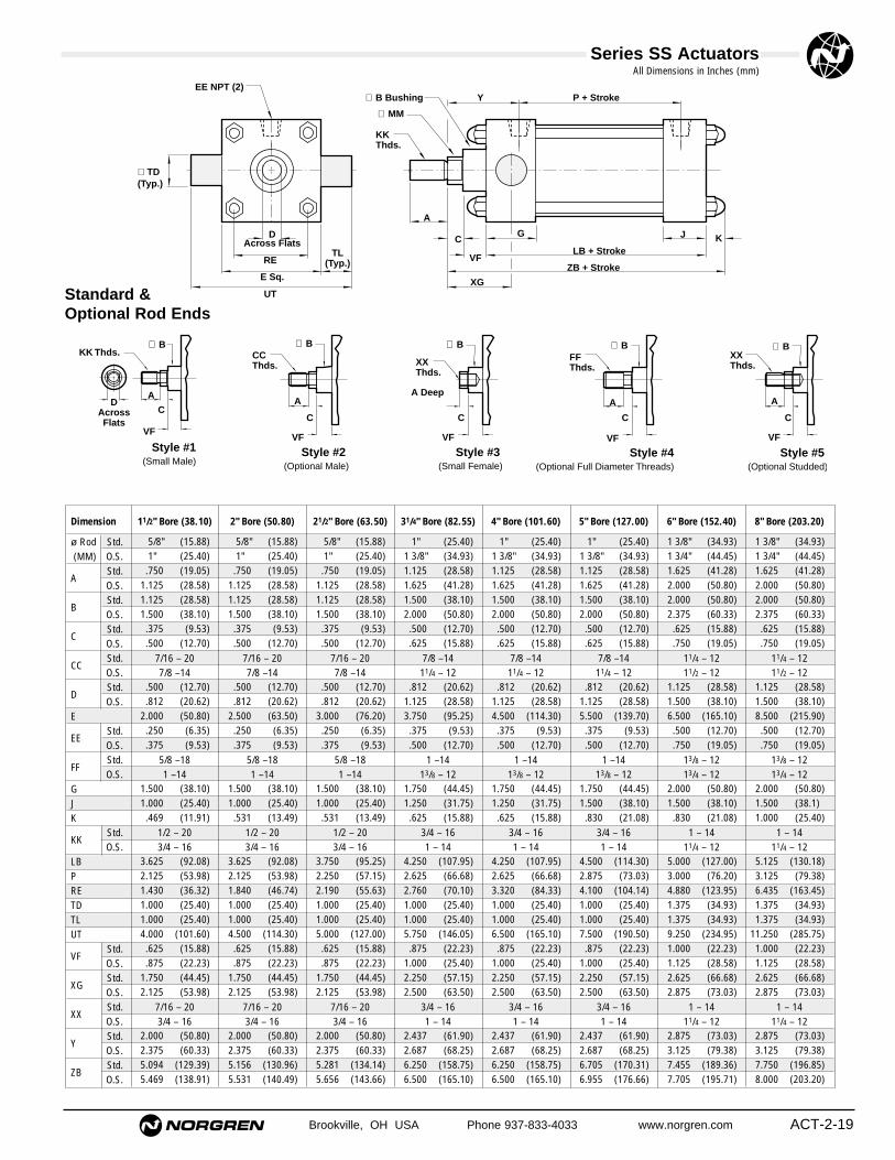
Brookville, OH USA Phone 937-833-4033 www.norgren.com ACT-2-19
Series SS ActuatorsAll Dimensions in Inches (mm)
EE NPT (2)
∅ TD(Typ.)
DAcross Flats
RE
E Sq.
UT
KK Thds.
∅ MM
∅ B Bushing Y P + Stroke
G
A
C
VF
XG
LB + Stroke
ZB + Stroke
KJ
TL(Typ.)
Standard & Optional Rod Ends
KK Thds.
DAcrossFlats
VF
A
∅ B
Style #1(Small Male)
C
∅ B ∅ B ∅ B ∅ BCCThds. XX
Thds.
A Deep
FFThds.
XXThds.
VF VF VF VF
A A A
Style #2 (Optional Male)
Style #3 (Small Female)
Style #4(Optional Full Diameter Threads)
Style #5 (Optional Studded)
CCCC

ACT-2-20 Brookville, OH USA Phone 937-833-4033 www.norgren.com
Series SS Actuators
● NFPA (MT2) 16 Cap Trunnion Mountavailable in 1-1/2" thru 8" bore sizes.
● Precision machined 300 Series stainless steel components.
● Cylinders rated to 250 PSI air,400 PSI hydraulic (non-shock).
● Designed for non-lube service.
● Switches available on all bore sizes.(See pages ACT-2-34/35 for ordering information.)
Actuator with 16 (MT2) Cap Trunnion
Cylinder Order Information
See ACT-2-26 for complete instructions on how to order cylinders.
Rod Size & StyleStandard OversizedA Male KK H Male KKB Male CC* J Male CCC Full Dia. Thd. K Full Dia. Thd.D Female XX M Female XXE Studded N StuddedX Special
Fractional Increments of StrokeA 0" J 1/2"B 1/16" K 9/16"C 1/8" M 5/8"D 3/16" N 11/16"E 1/4" P 3/4"F 5/16" R 13/16"G 3/8" S 7/8"H 7/16" T 15/16"X Special
Full Inches in Strokes00 0" Stroke01 1" Stroke02 2" Stroke03 3" Stroke04 4" Stroke05 5" Stroke06 6" Stroke. . . . . .
99 99" Strokexx Special
S Series SSD Series D
1
■
2
■
3
■
4
■
5
■
6
■
8
610
■
13
■
12
■
11
■
9
■
7
1– –
*On 11/2", 2" & 21/2" Bore Sizes with5/8" Rod, CC = 7/16 - 20 (NFPA)
PortsPosition 1† 2 3 4Standard A B C DOversized* E G H JSpecial X
Mounting Options01 Basic (MX0) 10 Head Square (ME3)*02 Bottom Tap (MS4) 11 Cap Square (ME4)*04 Front Flange (MF1) 15 Head Trunnion (MT1)05 Rear Flange (MF2) 16 Cap Trunnion (MT2)06 Cap Fixed Clevis (MP1) XX Special
No Options 00Magnetic Piston Only** 90Special∆ 98
**See ACT-2-34/35.∆ For any cylinder modifications not listed use “98” and please specify.
†Standard position*NFPA
1
4 2
3
Port and CushionNeedle Positions
(As viewed from rod end)
*8" Bores Only
Optional SealsNo Option AViton Seals 1Air/Oil Seal 3Metallic Rod Scraper 5Soft Touch 6Special X
CushionsNeedle Position 1 2 3† 4 No Cushions AHead Only B C D ECap Only G N/A J N/AHead and Cap N N/A P N/AFixed USpecial X
†Standard position
Bore Single Rod End11/2" C2" D21/2" E31/4" F4" G5" L6" J8" M

Dimension 11/2" Bore (38.10) 2" Bore (50.80) 21/2" Bore (63.50) 31/4" Bore (82.55) 4" Bore (101.60) 5" Bore (127.00) 6" Bore (152.40) 8" Bore (203.20)
ø Rod Std.(MM) O.S.
AStd.O.S.
B Std.O.S.
CStd.O.S.
CCStd. 7/16 – 20 7/16 – 20 7/16 – 20 7/8 –14 7/8 –14 7/8 –14 11/4 – 12 11/4 – 12O.S. 7/8 –14 7/8 –14 7/8 –14 11/4 – 12 11/4 – 12 11/4 – 12 11/2 – 12 11/2 – 12
DStd.O.S.
E
EEStd.O.S.
FFStd. 5/8 –18 5/8 –18 5/8 –18 1 –14 1 –14 1 –14 13/8 – 12 13/8 – 12O.S. 1 –14 1 –14 1 –14 13/8 – 12 13/8 – 12 13/8 – 12 13/4 – 12 13/4 – 12
GJK
KK Std. 1/2 – 20 1/2 – 20 1/2 – 20 3/4 – 16 3/4 – 16 3/4 – 16 1 – 14 1 – 14O.S. 3/4 – 16 3/4 – 16 3/4 – 16 1 – 14 1 – 14 1 – 14 11/4 – 12 11/4 – 12
LBPRETDTLUT
VFStd.O.S.
XJStd.O.S.
XXStd. 7/16 – 20 7/16 – 20 7/16 – 20 3/4 – 16 3/4 – 16 3/4 – 16 1 – 14 1 – 14O.S. 3/4 – 16 3/4 – 16 3/4 – 16 1 – 14 1 – 14 1 – 14 11/4 – 12 11/4 – 12
Y Std.O.S.
ZBStd.O.S.
(15.88) (15.88) (15.88) (25.40) (25.40) (25.40) (34.93) (34.93)(25.40) (25.40) (25.40) (34.93) (34.93) (34.93) (44.45) (44.45)(19.05) (19.05) (19.05) (28.58) (28.58) (28.58) (41.28) (41.28)(28.58) (28.58) (28.58) (41.28) (41.28) (41.28) (50.80) (50.80)(28.58) (28.58) (28.58) (38.10) (38.10) (38.10) (50.80) (50.80)(38.10) (38.10) (38.10) (50.80) (50.80) (50.80) (60.33) (60.33)(9.53) (9.53) (9.53) (12.70) (12.70) (12.70) (15.88) (15.88)
(12.70) (12.70) (12.70) (15.88) (15.88) (15.88) (19.05) (19.05)
(12.70) (12.70) (12.70) (20.62) (20.62) (20.62) (28.58) (28.58)(20.62) (20.62) (20.62) (28.58) (28.58) (28.58) (38.10) (38.10)(50.80) (63.50) (76.20) (95.25) (114.30) (139.70) (165.10) (215.90)(6.35) (6.35) (6.35) (9.53) (9.53) (9.53) (12.70) (12.70)(9.53) (9.53) (9.53) (12.70) (12.70) (12.70) (19.05) (19.05)
(38.10) (38.10) (38.10) (44.45) (44.45) (44.45) (50.80) (50.80)(25.40) (25.40) (25.40) (31.75) (31.75) (38.10) (38.10) (38.1)(11.91) (13.49) (13.49) (15.88) (15.88) (21.08) (21.08) (25.40)
(92.08) (92.08) (95.25) (107.95) (107.95) (114.30) (127.00) (130.18)(53.98) (53.98) (57.15) (66.68) (66.68) (73.03) (76.20) (79.38)(36.32) (46.74) (55.63) (70.10) (84.33) (104.14) (123.95) (163.45)(25.40) (25.40) (25.40) (25.40) (25.40) (25.40) (34.93) (34.93)(25.40) (25.40) (25.40) (25.40) (25.40) (25.40) (34.93) (34.93)
(101.60) (114.30) (127.00) (146.05) (165.10) (190.50) (234.95) (285.75)(15.88) (15.88) (15.88) (22.23) (22.23) (22.23) (22.23) (22.23)(22.23) (22.23) (22.23) (25.40) (25.40) (25.40) (28.58) (28.58)
(104.78) (104.78) (107.95) (127.00) (127.00) (133.35) (149.23) (152.40)(114.30) (114.30) (117.48) (133.35) (133.35) (139.70) (155.58) (158.75)
(50.80) (50.80) (50.80) (61.90) (61.90) (61.90) (73.03) (73.03)(60.33) (60.33) (60.33) (68.25) (68.25) (68.25) (79.38) (79.38)
(129.39) (130.96) (134.14) (158.75) (158.75) (170.31) (189.36) (196.85)(138.91) (140.49) (143.66) (165.10) (165.10) (176.66) (195.71) (203.20)
1.5/8" 1.5/8" 1.5/8" 1.1" 1.1" 1.1" 1.3/8" 1.3/8"1.1" 1.1" 1.1" 1.3/8" 1.3/8" 1.3/8" 1.3/4" 1.3/4".750 .750 .750 1.125 1.125 1.125 1.625 1.625
1.125 1.125 1.125 1.625 1.625 1.625 2.000 2.0001.125 1.125 1.125 1.500 1.500 1.500 2.000 2.0001.500 1.500 1.500 2.000 2.000 2.000 2.375 2.375.375 .375 .375 .500 .500 .500 .625 .625.500 .500 .500 .625 .625 .625 .750 .750
.500 .500 .500 .812 .812 .812 1.125 1.125
.812 .812 .812 1.125 1.125 1.125 1.500 1.5002.000 2.500 3.000 3.750 4.500 5.500 6.500 8.500.250 .250 .250 .375 .375 .375 .500 .500.375 .375 .375 .500 .500 .500 .750 .750
1.500 1.500 1.500 1.750 1.750 1.750 2.000 2.0001.000 1.000 1.000 1.250 1.250 1.500 1.500 1.500.469 .531 .531 .625 .625 .830 .830 1.000
3.625 3.625 3.750 4.250 4.250 4.500 5.000 5.1252.125 2.125 2.250 2.625 2.625 2.875 3.000 3.1251.430 1.840 2.190 2.760 3.320 4.100 4.880 6.4351.000 1.000 1.000 1.000 1.000 1.000 1.375 1.3751.000 1.000 1.000 1.000 1.000 1.000 1.375 1.3754.000 4.500 5.000 5.750 6.500 7.500 9.250 11.250.625 .625 .625 .875 .875 .875 1.000 1.000.875 .875 .875 1.000 1.000 1.000 1.125 1.125
4.125 4.125 4.250 5.000 5.000 5.250 5.875 6.0004.500 4.500 4.625 5.250 5.250 5.500 6.125 6.250
2.000 2.000 2.000 2.437 2.437 2.437 2.875 2.8752.375 2.375 2.375 2.687 2.687 2.687 3.125 3.1255.094 5.156 5.281 6.250 6.250 6.705 7.455 7.7505.469 5.531 5.656 6.500 6.500 6.955 7.705 8.000
Brookville, OH USA Phone 937-833-4033 www.norgren.com ACT-2-21
Series SS ActuatorsAll Dimensions in Inches (mm)
EE NPT (2)
∅ TD(Typ.)
∅ B Bushing
∅ MM
KK Thds.
DAcross Flats
RE
E Sq.
UT
TL(Typ.)
A
C
VF
G
Y P + Stroke
LB + Stroke
ZB + Stroke
XJ + Stroke
J K
Standard & Optional Rod Ends
KK Thds.
DAcrossFlats
VF
A
∅ B
Style #1(Small Male)
CA
C
∅ B ∅ B ∅ B ∅ BCCThds. XX
Thds.
A Deep
FFThds.
XXThds.
VF VF VF VF
A A A
Style #2 (Optional Male)
Style #3 (Small Female)
Style #4(Optional Full Diameter Threads)
Style #5 (Optional Studded)
CCCC

ACT-2-22 Brookville, OH USA Phone 937-833-4033 www.norgren.com
Series SS Actuators
● NFPA (MX0) 01 Basic Double Rod End Cylinder available in 1-1/2" thru 8" bore size.
● Precision machined 300 Series stainless steel components.
● Cylinders rated to 250 PSI air,400 PSI hydraulic (non-shock).
● Designed for non-lube service.
● Switches available on all bore sizes.(See pages ACT-2-34/35 for ordering information.)
Double Rod End Cylinder with 01(MX0) Basic
Cylinder Order Information
See ACT-2-26 for complete instructions on how to order cylinders.
Rod Size & StyleStandard OversizedA Male KK H Male KKB Male CC* J Male CCC Full Dia.Thd. K Full Dia. Thd.D Female XX M Female XXE Studded N StuddedX Special
Fractional Increments of StrokeA 0" J 1/2"B 1/16" K 9/16"C 1/8" M 5/8"D 3/16" N 11/16"E 1/4" P 3/4"F 5/16" R 13/16"G 3/8" S 7/8"H 7/16" T 15/16"X Special
Full Inches in Strokes00 0" Stroke01 1" Stroke02 2" Stroke03 3" Stroke04 4" Stroke05 5" Stroke06 6" Stroke. . . . . .
99 99" Strokexx Special
S Series SSD Series D
1
■
2
■
3
■
4
■
5
■
6
■
8
110
■
13
■
12
■
11
■
9
■
7
0– –
Bore Double Rod End11/2" Q2" R21/2" S31/4" T4" U5" Y6" W8" Z
*On 11/2", 2" & 21/2" Bore Sizes with5/8" Rod, CC = 7/16 - 20 (NFPA)
PortsPosition 1† 2 3 4Standard A B C DOversized* E G H JSpecial X
Mounting Options01 Basic (MX0) 10 Head Square (ME3)*02 Bottom Tap (MS4) 15 Head Trunnion (MT1)04 Front Flange (MF1) XX Special
No Options 00Magnetic Piston Only** 90Special∆ 98
**See ACT-2-34/35.∆ For any cylinder modifications not listed use “98” and please specify.
†Standard position*NFPA
1
4 2
3
Port and CushionNeedle Positions
(As viewed from rod end)
*8" Bores Only
CushionsNeedle Position 1 2† 3 4 No Cushions AHead Only B C D ECap Only G H J KHead and Cap N M P RFixed USpecial X
†Standard position
Optional SealsNo Option AViton Seals 1Air/Oil Seal 3Metallic Rod Scraper 5Soft Touch 6Special X

Dimension 11/2" Bore (38.10) 2" Bore (50.80) 21/2" Bore (63.50) 31/4" Bore (82.55) 4" Bore (101.60) 5" Bore (127.00) 6" Bore (152.40) 8" Bore (203.20)
ø Rod Std.(mm) O.S.
AStd.O.S.
B Std.O.S.
CStd.O.S.
CCStd. 7/16 – 20 7/16 – 20 7/16 – 20 7/8 –14 7/8 –14 7/8 –14 11/4 – 12 11/4 – 12O.S. 7/8 –14 7/8 –14 7/8 –14 11/4 – 12 11/4 – 12 11/4 – 12 11/2 – 12 11/2 – 12
DStd.O.S.
E
EEStd.O.S.
FFStd. 5/8 –18 5/8 –18 5/8 –18 1 –14 1 –14 1 –14 13/8 – 12 13/8 – 12O.S. 1 –14 1 –14 1 –14 13/8 – 12 13/8 – 12 13/8 – 12 13/4 – 12 13/4 – 12
GK
KK Std. 1/2 – 20 1/2 – 20 1/2 – 20 3/4 – 16 3/4 – 16 3/4 – 16 1 – 14 1 – 14O.S. 3/4 – 16 3/4 – 16 3/4 – 16 1 – 14 1 – 14 1 – 14 11/4 – 12 11/4– 12
LDPRE
VFStd.O.S.
XXStd. 7/16 – 20 7/16 – 20 7/16 – 20 3/4 – 16 3/4 – 16 3/4 – 16 1 – 14 1 – 14O.S. 3/4 – 16 3/4 – 16 3/4 – 16 1 – 14 1 – 14 1 – 14 11/4 – 12 11/4 – 12
Y Std.O.S.
ZMStd.O.S.
(15.88) (15.88) (15.88) (25.40) (25.40) (25.40) (34.93) (34.93)(25.40) (25.40) (25.40) (34.93) (34.93) (34.93) (44.45) (44.45)(19.05) (19.05) (19.05) (28.58) (28.58) (28.58) (41.28) (41.28)(28.58) (28.58) (28.58) (41.28) (41.28) (41.28) (50.80) (50.80)(28.58) (28.58) (28.58) (38.10) (38.10) (38.10) (50.80) (50.80)(38.10) (38.10) (38.10) (50.80) (50.80) (50.80) (60.33) (60.33)(9.53) (9.53) (9.53) (12.70) (12.70) (12.70) (15.88) (15.88)
(12.70) (12.70) (12.70) (15.88) (15.88) (15.88) (19.05) (19.05)
(12.70) (12.70) (12.70) (20.62) (20.62) (20.62) (28.58) (28.58)(20.62) (20.62) (20.62) (28.58) (28.58) (28.58) (38.10) (38.10)(50.80) (63.50) (76.20) (95.25) (114.30) (139.70) (165.10) (215.90)(6.35) (6.35) (6.35) (9.53) (9.53) (9.53) (12.70) (12.70)(9.53) (9.53) (9.53) (12.70) (12.70) (12.70) (19.05) (19.05)
(38.10) (38.10) (38.10) (44.45) (44.45) (44.45) (50.80) (50.80)(11.91) (13.49) (13.49) (15.88) (15.88) (21.08) (21.08) (25.40)
(104.78) (104.78) (107.95) (120.65) (120.65) (127.00) (139.70) (139.70)(53.98) (53.98) (57.15) (66.68) (66.68) (73.03) (76.20) (79.38)(36.32) (46.74) (55.63) (70.10) (84.33) (104.14) (123.95) (163.45)(15.88) (15.88) (15.88) (22.23) (22.23) (22.23) (22.23) (22.23)(22.23) (22.23) (22.23) (25.40) (25.40) (25.40) (28.58) (28.58)
(50.80) (50.80) (50.80) (61.90) (61.90) (61.90) (73.03) (73.03)(60.33) (60.33) (60.33) (68.25) (68.25) (68.25) (79.38) (79.38)
(155.58) (155.58) (158.75) (190.50) (190.50) (196.85) (222.25) (222.25)(174.63) (174.63) (177.80) (203.20) (203.20) (209.55) (234.95) (234.95)
.5/8" .5/8" .5/8" 1.1" 1.1" 1.1" 1.3/8" 1.3/8"1.1" 1.1" 1.1" 1.3/8" 1.3/8" 1.3/8" 1.3/4" 1.3/4".750 .750 .750 1.125 1.125 1.125 1.625 1.625
1.125 1.125 1.125 1.625 1.625 1.625 2.000 2.0001.125 1.125 1.125 1.500 1.500 1.500 2.000 2.0001.500 1.500 1.500 2.000 2.000 2.000 2.375 2.375.375 .375 .375 .500 .500 .500 .625 .625.500 .500 .500 .625 .625 .625 .750 .750
.500 .500 .500 .812 .812 .812 1.125 1.125
.812 .812 .812 1.125 1.125 1.125 1.500 1.5002.000 2.500 3.000 3.750 4.500 5.500 6.500 8.500.250 .250 .250 .375 .375 .375 .500 .500.375 .375 .375 .500 .500 .500 .750 .750
1.500 1.500 1.500 1.750 1.750 1.750 2.000 2.000.469 .531 .531 .625 .625 .830 .830 1.000
4.125 4.125 4.250 4.750 4.750 5.000 5.500 5.5002.125 2.125 2.250 2.625 2.625 2.875 3.000 3.1251.430 1.840 2.190 2.760 3.320 4.100 4.880 6.435.625 .625 .625 .875 .875 .875 1.000 1.000.875 .875 .875 1.000 1.000 1.000 1.125 1.125
2.000 2.000 2.000 2.437 2.437 2.437 2.875 2.8752.375 2.375 2.375 2.687 2.687 2.687 3.125 3.1256.125 6.125 6.250 7.500 7.500 7.750 8.750 8.7506.875 6.875 7.000 8.000 8.000 8.250 9.250 9.250
Brookville, OH USA Phone 937-833-4033 www.norgren.com ACT-2-23
Series SS ActuatorsAll Dimensions in Inches (mm)
EE NPT (2)
DAcross Flats
RE
E Sq.
∅ B Bushing
∅ MM
KK Thds.
A
C
VF
G
Y P + Stroke
LD + Stroke
ZM + (2 x Stroke)
GK
VF
Y + Stroke
∅ B Bushing∅ MM
KK Thds.
AC + Stroke
Standard & Optional Rod Ends
KK Thds.
DAcrossFlats
VF
A
∅ B
Style #1(Small Male)
C
∅ B ∅ B ∅ B ∅ BCCThds. XX
Thds.
A Deep
FFThds.
XXThds.
VF VF VF VF
A A A
Style #2 (Optional Male)
Style #3 (Small Female)
Style #4(Optional Full Diameter Threads)
Style #5 (Optional Studded)
CCCC
(19.05) (31.75) (38.10) (50.80)(12.70) (19.05) (25.40) (34.93)(38.10) (60.33) (79.38) (104.78)(25.40) (31.75) (38.10) (50.80)(12.70) (15.88) (19.05) (25.40)(12.70) (19.05) (25.40) (34.93)
(19.05) (31.75) (38.10) (53.98)
S-92-03 S-92-065 S-92-12 S-92-16CBCDCECHCWERKK 1/2-20 3/4-16 1-14 11/4 - 12L
.750 1.250 1.500 2.000
.500 .750 1.000 1.3751.500 2.375 3.125 4.1251.000 1.250 1.500 2.000.500 .625 .750 1.000.500 .750 1.000 1.375
.750 1.250 1.500 2.125
(41.28) (65.07) (82.55)(19.05) (31.75) (38.10)(12.70) (19.05) (25.40)(10.31) (13.49) (16.66)(63.50) (88.90) (114.30)(9.53) (15.88) (19.05)
(28.58) (47.63) (57.15)(19.05) (31.75) (38.10)(12.70) (19.05) (25.40)
1.625 2.562 3.250.750 1.250 1.500.500 .750 1.000.406 .531 .656
2.500 3.500 4.500.375 .625 .750
1.125 1.875 2.250.750 1.250 1.500.500 .750 1.000
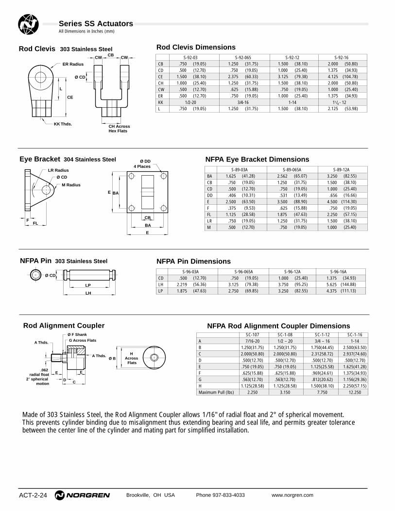
S-89-03A S-89-065A S-89-12A BACBCDDDEFFLLRM
NFPA Eye Bracket Dimensions
(12.70) (19.05) (25.40) (34.93)(56.36) (79.38) (95.25) (144.88)(47.63) (69.85) (82.55) (111.13)
.500 .750 1.000 1.3752.219 3.125 3.750 5.6251.875 2.750 3.250 4.375
S-96-03A S-96-065A S-96-12A S-96-16ACDLHLP
ACT-2-24 Brookville, OH USA Phone 937-833-4033 www.norgren.com
Series SS ActuatorsAll Dimensions in Inches (mm)
NFPA Rod Alignment Coupler Dimensions
ER Radius
KK Thds.
CE
L
Ø CD
CH AcrossHex Flats
CB CWCW
Rod Clevis 303 Stainless Steel Rod Clevis Dimensions
NFPA Pin Dimensions
Made of 303 Stainless Steel, the Rod Alignment Coupler allows 1/16" of radial float and 2° of spherical movement.This prevents cylinder binding due to misalignment thus extending bearing and seal life, and permits greater tolerancebetween the center line of the cylinder and mating part for simplified installation.
LR Radius
M Radius
Ø CD
FFL
E BA
Ø DD4 Places
CB
BA
E
Eye Bracket 304 Stainless Steel
LP
LH
Ø CD
NFPA Pin 303 Stainless Steel
������
�����
���
���
���
����
��
��
.062 radial float
2° spherical motion
A Thds.
Ø F Shank
G Across Flats
E
D C
E
A Thds.Ø B
H Across
Flats
Rod Alignment CouplerSC-107 SC-1-08 SC-1-12 SC-1-16
A 7/16-20 1/2 – 20 3/4 – 16 1-14B 1.250(31.75) 1.250(31.75) 1.750(44.45) 2.500(63.50)C 2.000(50.80) 2.000(50.80) 2.31258.72) 2.937(74.60)D .500(12.70) .500(12.70) .500(12.70) .500(12.70)E .750 (19.05) .750 (19.05) 1.125(25.58) 1.625(41.28)F .625(15.88) .625(15.88) .969(24.61) 1.375(34.93)G .563(12.70) .563(12.70) .812(20.62) 1.156(29.36)H 1.125(28.58) 1.125(28.58) 1.500(38.10) 2.250(57.15)Maximum Pull (lbs) 2.250 3.150 7.750 12.250

Brookville, OH USA Phone 937-833-4033 www.norgren.com ACT-2-25
Series SS Actuators
���������� ���������
��������
����������
������������������
��������
��� ������������
������������
�����������
��
��
��
��
��
��
��
��
������������
������
����
���
Multi-Position DuplexAir-to-Air Booster/Pump
Force Multiplication TandemMulti-Position Back-to-Back
Air/Oil Piston SealPrevents leakage past the seal in air/oil applications. This addedprotection is accomplished by usingone loaded lip-type piston seal.TO ORDER: enter 3 in position 11 ofthe model number.
Stop TubeProvides increased stability to longstroke cylinders. TO ORDER: Indicate full workingstroke in positions 3, 4 & 5 of themodel number. Enter 98 in positions12 & 13 of the model number andspecify: 98 = _____inches of stop tube.
303 Stainless Steel PistonWhen internal corrosion is a concern,specify the 303 Stainless SteelPiston.
Metallic Rod ScraperAggressively scrapes foreign materialsfrom the exposed portion of the pistonrod during retract, thereby protectingthe rod seal.TO ORDER: enter 5 in position 11 ofthe model number.
Protective Rod Boot
Norgren designs and manufactures literally hundreds of specialty cylinders. We welcome the opportunity to provide you with a customized cylinder that meets the specific requirements of your application. For more information on how to order custom cylinders consult factory.
Optional features should be specified at the time of cylinder order. Enter 98 in positions 12 & 13 of the model number and specify: Example 98 = 303 stainless steel piston.
● Extra long cushions.● Extremely low breakaway.● High temperature.● Stop tube.● Spring extend/retract.● Non-rotating rod.● Oversized piston rods.
Optional Features
Custom Cylinders
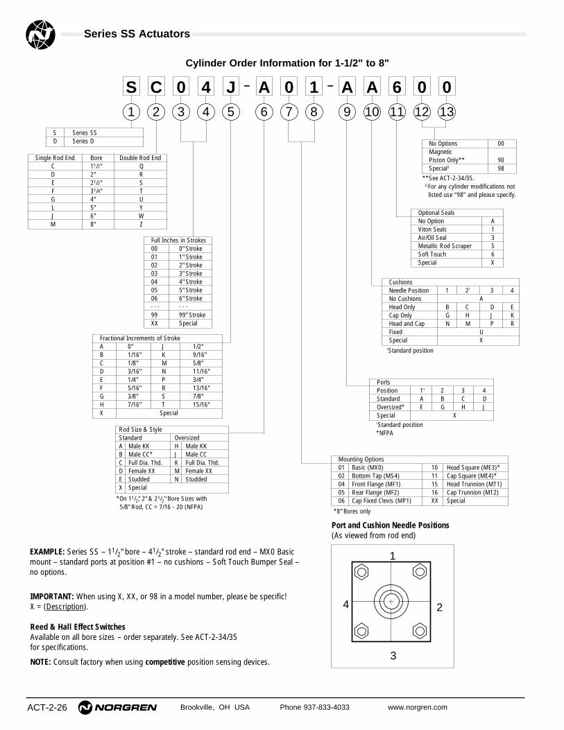
ACT-2-26 Brookville, OH USA Phone 937-833-4033 www.norgren.com
Series SS Actuators
Port and Cushion Needle Positions(As viewed from rod end)
Single Rod End Bore Double Rod EndC 11/2" QD 2" RE 21/2" SF 31/4" TG 4" UL 5" YJ 6" WM 8" Z
Cylinder Order Information for 1-1/2" to 8"
CushionsNeedle Position 1 2† 3 4 No Cushions AHead Only B C D ECap Only G H J KHead and Cap N M P RFixed USpecial X
PortsPosition 1† 2 3 4Standard A B C DOversized* E G H JSpecial X
Mounting Options01 Basic (MX0) 10 Head Square (ME3)*02 Bottom Tap (MS4) 11 Cap Square (ME4)*04 Front Flange (MF1) 15 Head Trunnion (MT1)05 Rear Flange (MF2) 16 Cap Trunnion (MT2)06 Cap Fixed Clevis (MP1) XX Special
Rod Size & StyleStandard OversizedA Male KK H Male KKB Male CC* J Male CCC Full Dia. Thd. K Full Dia. Thd.D Female XX M Female XXE Studded N StuddedX Special
Fractional Increments of StrokeA 0" J 1/2"B 1/16" K 9/16"C 1/8" M 5/8"D 3/16" N 11/16"E 1/4" P 3/4"F 5/16" R 13/16"G 3/8" S 7/8"H 7/16" T 15/16"X Special
Full Inches in Strokes00 0" Stroke01 1" Stroke02 2" Stroke03 3" Stroke04 4" Stroke05 5" Stroke06 6" Stroke. . . . . .
99 99" StrokeXX Special
S Series SSD Series D No Options 00
Magnetic Piston Only** 90Special∆ 98
1
S2
C3
04
45
J6
A8
110
A13
012
011
69
A7
0– –
**See ACT-2-34/35.∆ For any cylinder modifications not listed use “98” and please specify.
†Standard position
†Standard position*NFPA
*On 11/2", 2" & 21/2" Bore Sizes with5/8" Rod, CC = 7/16 - 20 (NFPA)
*8" Bores only
1
4 2
3
IMPORTANT: When using X, XX, or 98 in a model number, please be specific! X = (Description).
Reed & Hall Effect SwitchesAvailable on all bore sizes – order separately. See ACT-2-34/35 for specifications.
NOTE: Consult factory when using competitive position sensing devices.
EXAMPLE: Series SS – 11/2" bore – 41/2" stroke – standard rod end – MX0 Basicmount – standard ports at position #1 – no cushions – Soft Touch Bumper Seal – no options.
Optional SealsNo Option AViton Seals 1Air/Oil Seal 3Metallic Rod Scraper 5Soft Touch 6Special X

Brookville, OH USA Phone 937-833-4033 www.norgren.com ACT-2-27
Series SS ActuatorsAll Dimensions in Inches (mm)
Tube: Corrosion-resistant 304stainless steel.7
Superior operating performance in a 1-1/8" bore size!Piston: Solid aluminum alloy,
light-weight for low inertia, yet strong.
Head/Cap: Precision machined from solid corrosion-resistant 304 stainless steel bar.
Piston Seals: Lip-type nitrile seals are pressure energized and wearcompensating. Their excellent lubricationretention characteristics lower seal frictionand ensure long life.
Piston Rods: 303 stainless steel,40,000 PSI minimum yield, hard chromeplated, ground and polished.
Bearing Seal: Teflon® rod wiperprovides positive wiping action and lowfriction. Lip-type nitrile seal is pressureenergized and wear compensating for long life.
1 5
4
3
2
Wear Strip: Teflon® and graphitecomposition for minimum friction,maximum wear and side load resistance.(Magnetic band under wear strip optional.)
Tie Rods: High-strength 303 stainless steel maintains compression on tube and seals.
Rod Bearing: Incorporates a sinteredbronze rod bearing which is pressed into thecylinder head.
Acorn Nut: Tie rod threads are covered by stainless steel acorn nuts which eliminate another bacteria hiding place.
6 8
109
Norgren’s state-of-the-art Ultra Cushion® designand Soft Touch Bumper Seal are also available on our 11/8" bore. (See ACT-2-3.)
Cushions permit the trapping of cylinder exhaustvolume prior to the completion of full rodextension or retraction. This volume is thenmetered through a finely tapered needle to deliversmooth, adjustable deceleration of the cylinder load.
Note: Cushion block increases stroke relateddimensions by .500 per end.
Cushions are not available on 11/8" bore with 1/2" diameter rod.
.173
.062
#10 - 40 Thread
.480
1.094
.500
.500
.844
.480
Optional Features
3
11
23
5
4
89
10
76

ACT-2-28 Brookville, OH USA Phone 937-833-4033 www.norgren.com
Series SS Actuators
∅ MM CC Thds.
Y P + Stroke
AC
V
G
LB + StrokeZF + Stroke
J FH
FB Holes (4)EE
NPT (2)
TFUF
R E
1-1/8" Cylinder with01 (MX0) Basic
EE NPT (2)
D(Flats)∅ RMESq.
∅ MM
CC Thds.
A
V
C G
Y P + Stroke
LB + StrokeZB + Stroke
J K
∅ DB Hole Thru∅ TB C'Bore for
SB Screws3 Places
DN
D(Flats)∅ RMESq.
∅ MM
CC Thds.
A
V
C G
XB H
SD + Stroke
.375 (9.53)
LB + StrokeZB + Stroke
J
K
1-1/8" Cylinder with04 (MF7) Front Flange
1-1/8" Cylinder with03 (MS8) Bolt Thru
EE NPT (2)FB Holes (4)
E R
D(Flats)
TFUF
∅ MM
CCThds.
Y P + Stroke
LB + StrokeZB + Stroke
G
A
W
FH
J K
1-1/8" Cylinder with05 (MF2) Rear Flange
Cylinder with 01 (MX0) BasicCylinder with 03 (MS8) Bolt Thru Cylinder with 04 (MF7) Front Flange Cylinder with 05 (MF2) Rear Flange
See ACT-2-33 for complete instructions on how to order cylinders.

(9.53) (9.53) (9.53) (9.53)(12.70) (12.70) (12.70) (12.70)(15.88) (15.88) (15.88) (15.88)(19.05) (19.05) (19.05) (19.05)(6.35) (6.35) (6.35) (6.35)
(7.92) (7.92) (7.92) (7.92)(11.10) (11.10) (11.10) (11.10)
(5.16)(25.40)
(38.10) (38.10) (38.10) (38.10)(3.18) (3.18) (3.18) (3.18)
(5.56) (5.56)(6.35) (6.35)
(22.23) (22.23) (22.23) (22.23)(15.88)
(15.88) (15.88) (15.88) (15.88)(10.16) (10.16) (10.16)
(57.15) (57.15) (57.15) (57.15)(9.40) (9.40) (9.40) (9.40)
(12.57) (12.57) (12.57) (12.57)(34.93) (34.93) (34.93)
(25.40) (25.40)(19.05) (19.05)(25.40) (25.40)
(44.45)(8.33)
(50.80) (50.80)(63.50) (63.50)
(3.18) (3.18) (3.18) (3.18)(3.18)
(15.88)
(23.82) (23.82) (23.82)(66.68) (66.68) (66.68)
(73.03)
.3/8" .3/8" .3/8" .3/8"
.1/2" .1/2" .1/2" .1/2"
.625 .625 .625 .625
.750 .750 .750 .750
.250 .250 .250 .250
.312 .312 .312 .312
.437 .437 .437 .437.203
1.0001.500 1.500 1.500 1.500.125 .125 .125 .125
.219 .219
.250 .250.875 .875 .875 .875
.625.625 .625 .625 .625.400 .400 .400
2.250 2.250 2.250 2.250.370 .370 .370 .370.495 .495 .495 .495
1.375 1.375 1.3751.000 1.000
.750 .7501.000 1.000
1.750.328
2.000 2.0002.500 2.500
.125 .125 .125 .125.125
.625
.938 .938 .9382.625 2.625 2.625
2.875
Dimension Cylinder with 01 (MXO) Basic Cylinder with 03 (MS8) Bolt Thru Cylinder with 04 (MF7) Front Flange Cylinder with 05 (MF2) Rear Flange
ø RodStd.O.S.
AStd.O.S.
C
CCStd. 3/8 - 24 3/8 - 24 3/8 - 24 3/8 - 24O.S. 1/2 - 20 1/2 - 20 1/2 - 20 1/2 - 20
DStd.O.S.
DB – – –DN – – –EEEFB – –FH – –GH – – –JK –
KK Std. 5/16 - 24 5/16 - 24 5/16 - 24 5/16 - 24O.S. 7/16 - 20 7/16 - 20 7/16 - 20 7/16 - 20
LB
MMStd.O.S.
P –R – –
RMStd. – –O.S. – –
SBStd. – #10 – –O.S. – #10 – –
SD – – –TB – – –TF – –UF – –VW – – –XB – – –
XXStd. 1/4 - 28 1/4 - 28 1/4 - 28 1/4 - 28O.S. 3/8 - 24 3/8 - 24 3/8 - 24 3/8 - 24
Y –ZB –ZF – – –
Brookville, OH USA Phone 937-833-4033 www.norgren.com ACT-2-29
Series SS ActuatorsAll Dimensions in Inches (mm)
Standard & Optional Rod Ends
KK Thds.
AC
V
XX Thds. A Deep
C
V
Style #2 (Optional Male)
Style #3 (Optional Female)
CC Thds.
DAcrossFlats
A C
V
Style #1 (Standard Male)

ACT-2-30 Brookville, OH USA Phone 937-833-4033 www.norgren.com
Series SS Actuators
1-1/8" Cylinder with 22 (MS9) Side Tap
1-1/8" Cylinder with30 (MR1) Head Face
1-1/8" Double Rod EndCylinder with 01 (MX0) Basic
1-1/8" Cylinder with17 (MP3) Fixed Eye
EE NPT (2)
ESq.
TNNT TapTK Deep
∅ MM
CC Thds.
AC G
Y
XTV
P + Stroke
SN + Stroke
LB + StrokeZB + Stroke
J K
EE NPT (2)
ESq.
D(Flats)
∅ RMRE
∅ MM
CC Thds.
A
RT Thds.on ∅ BC Bolt Circle
C
V
G
Y P + Stroke
LB + Stroke
ZB + Stroke
JK
EE NPT (2)
D(Flats)∅ RMESq.
G
K
P + Stroke
LB + StrokeZB + (2 x Stroke)
G C
A
V
Y
∅ MMCC Thds.
∅ MMCC Thds.
AC
V
G
Y P + Stroke
LB + StrokeXC + Stroke
J LM
∅ CD
ESq.
CB
EE NPT (2)
See ACT-2-33 for complete instructions on how to order cylinders.
Cylinder with 17 (MP3) Fixed Eye Cylinder with 22 (MS9) Side Tap Cylinder with 30 (MR1) Head Face Double Rod End Cylinder with 01 (MX0) Basic

.3/8" .3/8" .3/8" .3/8"
.1/2" .1/2" .1/2" .1/2"
.625 .625 .625 .625
.750 .750 .750 .7501.593
.250 .250 .250 .250
.375
.375
.312 .312 .312 .312
.437 .437 .437 .4371.500 1.500 1.500 1.500.125 .125 .125 .125.875 .875 .875 .875.625. .625 .625 .625
.400 .400 .400
.4372.250 2.250 2.250 2.250.375.370 .370 .370 .370.495 .495 .495 .495
1.375 1.375 1.375 1.3751.125.750 .750
1.000 1.000
1.750.250
1.000.125 .125 .125 .125
3.062.625
.938 .938 .938 .9382.625 2.625 3.250
(9.53) (9.53) (9.53) (9.53)(12.70) (12.70) (12.70) (12.70)(15.88) (15.88) (15.88) (15.88)(19.05) (19.05) (19.05) (19.05)
(40.46)(6.35) (6.35) (6.35) (6.35)(9.53)
(9.53)(7.92) (7.92) (7.92) (7.92)
(11.10) (11.10) (11.10) (11.10)(38.10) (38.10) (38.10) (38.10)(3.18) (3.18) (3.18) (3.18)
(22.23) (22.23) (22.23) (22.23)(15.88) (15.88) (15.88) (15.88)
(10.16) (10.16) (10.16)
(11.10)(57.15) (57.15) (57.15) (57.15)(9.53)(9.40) (9.40) (9.40) (9.40)
(12.57) (12.57) (12.57) (12.57)
(34.93) (34.93) (34.93) (34.93)(28.58)(19.05) (19.05)(25.40) (25.40)
(44.45)(6.35)
(25.40)(3.18) (3.18) (3.18) (3.18)
(77.77)(15.88)
(23.83) (23.83) (23.83) (23.83)(66.68) (66.68) (82.55)
Dimension Cylinder with 17 (MP3) Fixed Eye Cylinder with 22 (MS9) Side Tap Cylinder with 30 (MR1) Head Face Double Rod End Cylinder with 01 (MX0)
ø RodStd.O.S.
AStd.O.S.
BC – – –CCB – – –
CCStd. 3/8 - 24 3/8 - 24 3/8 - 24 3/8 - 24O.S. 1/2 - 20 1/2 - 20 1/2 - 20 1/2 - 20
CD – – –
DStd.O.S.
EEEGJK – –
KK Std. 5/16 - 24 5/16 - 24 5/16 - 24 5/16 - 24O.S. 7/16 - 20 7/16 - 20 7/16 - 20 7/16 - 20
L – – –LBM – – –
MMStd.O.S.
NT – 10 - 32 – –PRE – – –
RMStd. – –O.S. – –
RT – – 10 - 32 –SN – – –TK – – –TN – – –VXC – – –XT – – –
XXStd. 1/4 - 28 1/4 - 28 1/4 - 28 1/4 - 28O.S. 3/8 - 24 3/8 - 24 3/8 - 24 3/8 - 24
YZB –
Brookville, OH USA Phone 937-833-4033 www.norgren.com ACT-2-31
Series SS ActuatorsAll Dimensions in Inches (mm)
Standard & Optional Rod Ends
KK Thds.
AC
V
XX Thds. A Deep
C
V
Style #2 (Optional Male)
Style #3 (Optional Female)
CC Thds.
DAcrossFlats
A C
V
Style #1 (Standard Male)

ACT-2-32 Brookville, OH USA Phone 937-833-4033 www.norgren.com
Series SS ActuatorsAll Dimensions in Inches (mm)
(22.23)(31.75)(6.35)
(15.88)(9.53)(7.92)
(19.05)
.8751.250.250.625.375.312.750
SC-1-06A 3/8 – 24BCDEFGHMaximum Pull (lbs.) 1,375
1.125.375.375.250.328.203.500.500
1.125.625.375.312
S-91-225BACBCDCWDBDDEFFLLRMTB
(28.58)(9.53)(9.53)(6.35)(8.33)(5.16)
(12.70)(12.70)(28.58)(15.88)(9.53)(7.92)
.3751.2501.032
S-96-225A**CDLHLP
(9.53)(31.75)(26.21)
.437 .437
.875 .875
.375 .375
.375 .375
.375 .375
.750 .750
.219 .312
(11.10) (11.10)(22.23) (22.23)(9.53) (9.53)(9.53) (9.53)(9.53) (9.53)
(19.05) (19.05)
(5.56) (7.92)
S-97-225* S-97-225A*ACACBCDERHKK 3/8-24 1/2-20N
NFPA Rod Alignment Coupler Dimensions
Ø CD
M Radius
LR Radius
FFL
Clevis Bracket 304 Stainless Steel Ø DDØ DB C’Bore
TB Deep4 Places
CB
CWCWBA
BA
E
E
Clevis Bracket Dimensions
ER Radius
KK Thds.A Deep
CA
A
Ø CD
HSq.
N
CB
Rod Eye 303 Stainless Steel Rod Eye Dimensions
Pivot Pin Dimensions
LP
LH
Ø CD
Pivot Pin 303 Stainless Steel
������
�����
���
���
���
����
��
��
.062 radial float
2° spherical motion
A Thds.
Ø F Shank
G Across Flats
E
D C
E
A Thds.Ø B
H Across
Flats
Rod Alignment Coupler
*Includes Jam Nut
**Use with S-91-225, S-97-225
Made of 303 Stainless Steel, the Rod Alignment Coupler allows 1/16" of radial float and 2° of spherical movement.This prevents cylinder binding due to misalignment thus extending bearing and seal life, and permits greater tolerancebetween the center line of the cylinder and mating part for simplified installation.

Brookville, OH USA Phone 937-833-4033 www.norgren.com ACT-2-33
Series SS Actuators
Cylinder Order Information for 1-1/8"
CushionsNeedle Position 1 2† 3 4 No Cushions AHead Only B C D ECap Only G H J KHead and Cap N M P RFixed USpecial X
PortsPosition 1† 2 3 4Standard A B C DSpecial X
Mounting Options01 Basic (MX0) 17 Fixed Eye (MP3)03 Bolt Thru (MS8) 22 Side Tap (MS9)04 Front Flange (MF7) 30 Head Face (MR1)05 Rear Flange (MF2) XX Special
Fractional Increments of StrokeA 0" J 1/2"B 1/16" K 9/16"C 1/8" M 5/8"D 3/16" N 11/16"E 1/4" P 3/4"F 5/16" R 13/16"G 3/8" S 7/8"H 7/16" T 15/16"X Special
Full Inches in Strokes00 0" Stroke01 1" Stroke02 2" Stroke03 3" Stroke04 4" Stroke05 5" Stroke06 6" Stroke. . . . . .
99 99" StrokeXX Special
S Series SSD Series D No Options 00
Magnetic Piston Only** 90Special∆ 98
1
S2
B3
04
45
J6
B8
110
A13
012
011
69
A7
0– –
**See ACT-2-34/35.∆ For any cylinder modifications not listed use “98” and please specify.
†Standard positionNote: Cushions are not available on 11/8" bore with 1/2" diameter rod.
†Standard position
*Standard Rod End 11/8" Bore (3/8 - 24)
IMPORTANT: When using X, XX, or 98 in a model number, please be specific! X = (Description).
Reed & Hall Effect SwitchesAvailable on all bore sizes – order separately. See ACT-2-34/35 for specifications.
NOTE: Consult factory when using competitive position sensing devices.
EXAMPLE: Series SS – 11/8" bore – 41/2" stroke – standard rod end – MX0 Basicmount – standard ports at position #1 – no cushions – Soft Touch Bumper Seal – no options.
Rod Size & StyleStandard OversizedA Male KK H Male KKB Male CC* J Male CCD Female XX M Female XXX Special
Single Rod End Bore Double Rod EndB 11/8" P
Port and Cushion Needle Positions(As viewed from rod end)
1
4 2
3
Optional SealsNo Option AViton Seals 1Air/Oil Seal 3Metallic Rod Scraper 5Soft Touch 6Special X
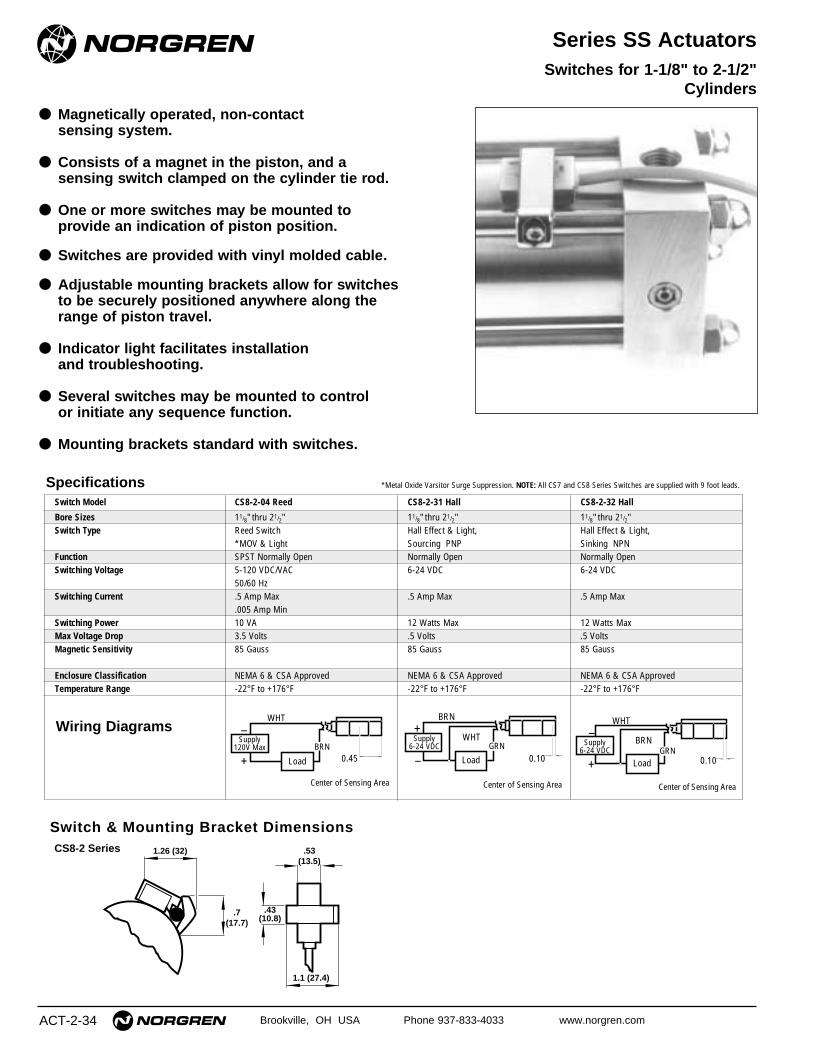
ACT-2-34 Brookville, OH USA Phone 937-833-4033 www.norgren.com
Series SS Actuators
● Magnetically operated, non-contact sensing system.
● Consists of a magnet in the piston, and a sensing switch clamped on the cylinder tie rod.
● One or more switches may be mounted to provide an indication of piston position.
● Switches are provided with vinyl molded cable.
● Adjustable mounting brackets allow for switches to be securely positioned anywhere along the range of piston travel.
● Indicator light facilitates installation and troubleshooting.
● Several switches may be mounted to control or initiate any sequence function.
● Mounting brackets standard with switches.
Switches for 1-1/8" to 2-1/2"Cylinders
Specifications
Wiring Diagrams
*Metal Oxide Varsitor Surge Suppression. NOTE: All CS7 and CS8 Series Switches are supplied with 9 foot leads.
CS8-2 Series 1.26 (32)
.7(17.7)
.43(10.8)
.53(13.5)
1.1 (27.4)
Switch & Mounting Bracket Dimensions
Switch Model CS8-2-04 Reed CS8-2-31 Hall CS8-2-32 Hall
Bore Sizes 11/8" thru 21/2" 11/8" thru 21/2" 11/8" thru 21/2"Switch Type Reed Switch Hall Effect & Light, Hall Effect & Light,
*MOV & Light Sourcing PNP Sinking NPNFunction SPST Normally Open Normally Open Normally OpenSwitching Voltage 5-120 VDC/VAC 6-24 VDC 6-24 VDC
50/60 HzSwitching Current .5 Amp Max .5 Amp Max .5 Amp Max
.005 Amp MinSwitching Power 10 VA 12 Watts Max 12 Watts MaxMax Voltage Drop 3.5 Volts .5 Volts .5 VoltsMagnetic Sensitivity 85 Gauss 85 Gauss 85 Gauss
Enclosure Classification NEMA 6 & CSA Approved NEMA 6 & CSA Approved NEMA 6 & CSA ApprovedTemperature Range -22°F to +176°F -22°F to +176°F -22°F to +176°F
Supply6-24 VDC
Supply6-24 VDC
Supply120V Max
0.45 0.100.10
–
–
–
+
+
+
Center of Sensing AreaCenter of Sensing AreaCenter of Sensing Area
LoadLoadLoad
BRN
WHT
WHT
WHT
BRN
BRN
GRNGRN
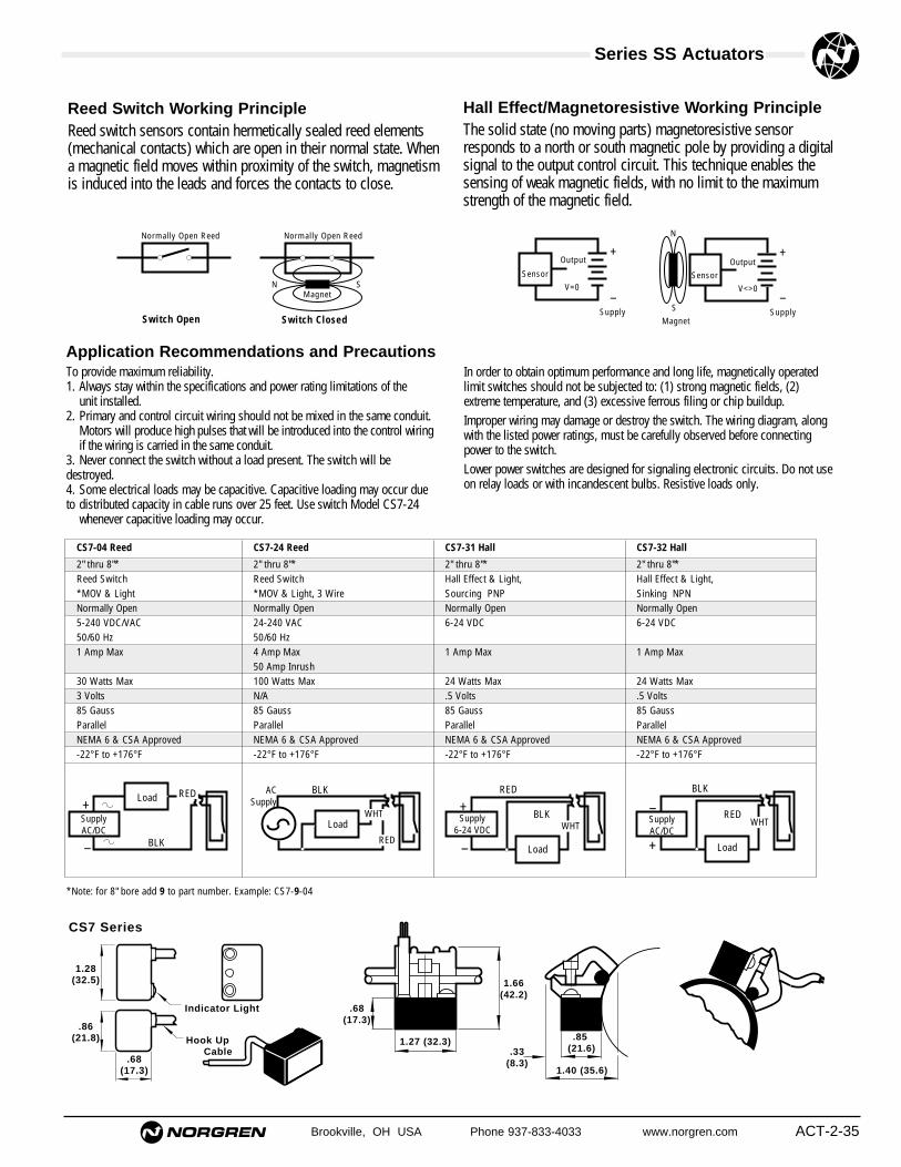
Brookville, OH USA Phone 937-833-4033 www.norgren.com ACT-2-35
Series SS Actuators
SMagnet
SensorOutput
Supply–
+
V<>0–
+
Supply
Sensor
N
V=0
Output
*Note: for 8" bore add 9 to part number. Example: CS7-9-04
Hook Up Cable
Indicator Light
CS7 Series
.68(17.3)
.86(21.8)
1.28(32.5)
.68(17.3)
1.27 (32.3)
1.66(42.2)
.33(8.3)
1.40 (35.6)
.85 (21.6)
Reed Switch Working PrincipleReed switch sensors contain hermetically sealed reed elements (mechanical contacts) which are open in their normal state. When a magnetic field moves within proximity of the switch, magnetism is induced into the leads and forces the contacts to close.
In order to obtain optimum performance and long life, magnetically operatedlimit switches should not be subjected to: (1) strong magnetic fields, (2) extreme temperature, and (3) excessive ferrous filing or chip buildup.Improper wiring may damage or destroy the switch. The wiring diagram, alongwith the listed power ratings, must be carefully observed before connectingpower to the switch.Lower power switches are designed for signaling electronic circuits. Do not useon relay loads or with incandescent bulbs. Resistive loads only.
Normally Open Reed Normally Open Reed
N SMagnet
Switch Open Switch Closed
Hall Effect/Magnetoresistive Working PrincipleThe solid state (no moving parts) magnetoresistive sensorresponds to a north or south magnetic pole by providing a digitalsignal to the output control circuit. This technique enables thesensing of weak magnetic fields, with no limit to the maximumstrength of the magnetic field.
Application Recommendations and PrecautionsTo provide maximum reliability.1. Always stay within the specifications and power rating limitations of the
unit installed.2. Primary and control circuit wiring should not be mixed in the same conduit.
Motors will produce high pulses that will be introduced into the control wiringif the wiring is carried in the same conduit.
3. Never connect the switch without a load present. The switch will bedestroyed.4. Some electrical loads may be capacitive. Capacitive loading may occur dueto distributed capacity in cable runs over 25 feet. Use switch Model CS7-24
whenever capacitive loading may occur.
CS7-04 Reed CS7-24 Reed CS7-31 Hall CS7-32 Hall
2" thru 8"* 2" thru 8"* 2" thru 8"* 2" thru 8"*Reed Switch Reed Switch Hall Effect & Light, Hall Effect & Light,*MOV & Light *MOV & Light, 3 Wire Sourcing PNP Sinking NPNNormally Open Normally Open Normally Open Normally Open5-240 VDC/VAC 24-240 VAC 6-24 VDC 6-24 VDC50/60 Hz 50/60 Hz1 Amp Max 4 Amp Max 1 Amp Max 1 Amp Max
50 Amp Inrush30 Watts Max 100 Watts Max 24 Watts Max 24 Watts Max3 Volts N/A .5 Volts .5 Volts85 Gauss 85 Gauss 85 Gauss 85 Gauss Parallel Parallel Parallel ParallelNEMA 6 & CSA Approved NEMA 6 & CSA Approved NEMA 6 & CSA Approved NEMA 6 & CSA Approved-22°F to +176°F -22°F to +176°F -22°F to +176°F -22°F to +176°F
ACSupply
SupplyAC/DC
SupplyAC/DC
Supply6-24 VDC
–
–– +
++
LoadLoad
Load
Load
RED
RED BLK
BLK
BLK
BLK
WHTWHTWHT
RED
RED


