Model: DVP - Vapour Pressure Analyzer - Issue: DVP-0401-R2 Page 1
FEATURES
• The sample is sprayed from a nozzle at a constant temperatureand the vapour pressure is continuously determined from staticpressure of the sample fluid.
• Correlation with vapour pressure measured by Reid methodspecified under JIS K2258 and ASTM D323.
• Flameproof explosion protected construction (JIS d2G4) for use inoil refinery plants. Equivalent to NEC Class1, Group D, Div1.
STANDARD SPECIFICATIONS
Product Name : Vapour pressure analyser Model : DVP Measurement Object : Vapour pressure of oil products such
as automobile gasoline, aircraftgasoline and jet oil
Measurement Method : Dynamic pressure measurement of thesample sprayed from nozzle(Correlated with JIS K2258 andASTM-D323: Continuous)
Explosion Protection StandardFlameproof explosion protected construction d2G4Certification No.3961 (Body)Certification No.26646 (Temperature regulator)
Measurement Ranges : 0~100kPa/cm2 or 0~150kPa/cm2
Repeatability : ±1kPa FS or lessLinearity : Within 0.5%of FSResponse Time : Within 60 sec. For 90% responseAmbient Temperature : 0~40oCSample Conditions
Temperature : 20~35oCFlow rate : 1~3 L/min.Inlet pressure : 5~35kgf/cm2
Outlet pressure : Atmospheric pressureViscosity : 9.5CP or less
Cooling Water ConditionsTemperature : 0~32oCFlow rate : 0~2L/min.Pressure : Min. 1kgf/cm2
Power Requirements : 100V AC±10%, 50/60Hz (otheroperating voltages available asoptions.)
Power Consumption : 2KVA Construction : Self-stand frameDimensions : 1500(w) x 700(d) x 1500(h) mmWeight : Approx.600kg Paint Colour : Metallic silver
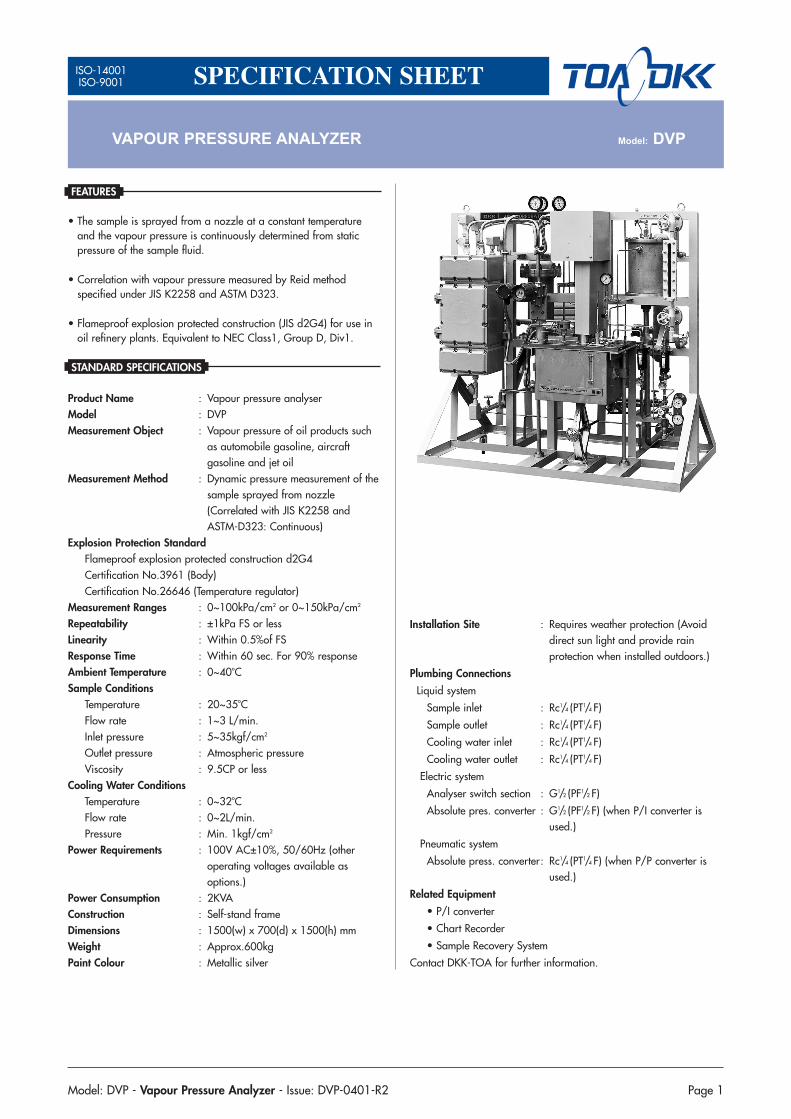
VAPOUR PRESSURE ANALYZER Model: DVP
Installation Site : Requires weather protection (Avoiddirect sun light and provide rainprotection when installed outdoors.)
Plumbing Connections
Liquid system
Sample inlet : Rc1/4 (PT1/4 F)
Sample outlet : Rc1/4 (PT1/4 F)
Cooling water inlet : Rc1/4 (PT1/4 F)
Cooling water outlet : Rc1/4 (PT1/4 F)
Electric system
Analyser switch section : G1/2 (PF1/2 F)
Absolute pres. converter : G1/2 (PF1/2 F) (when P/I converter isused.)
Pneumatic system
Absolute press. converter: Rc1/4 (PT1/4 F) (when P/P converter isused.)
Related Equipment
• P/I converter
• Chart Recorder
• Sample Recovery System
Contact DKK-TOA for further information.
ISO-14001ISO-9001 SPECIFICATION SHEET

Page 2 Model: DVP - Vapour Pressure Analyzer - Issue: DVP-0401-R2
PRINCIPLE OF OPERATION
The sample is sprayed from a nozzle at a constant temperature(100°F , 37.8oC) and at a constant pressure. The sample pressure ismeasured from the pressure when vaporized. This analyser employsthe Kinetic Vapour Pressure which is correlated with the Reid VapourPressure method. (The method in which the pressure of the spaceabove the sample in a fixed vessel is measured as the vapourpressure.)
The sample is taken off from the process flow path and is subjected toadjustment to a fixed pressure (usually 3kgf/cm2G) at the regulatorVG via strainer Y1, and enters the thermostat bath BC. Thethermostat bath contains non-flammable insulation oil B as thethermal medium and its temperature is kept at 37.8oC. The samplereaches equilibrium at this temperature while it passed through theheat exchanger E. It is then sprayed from the nozzle at high speed tobe vaporized. Since the outlet pressure of the nozzle openingcorresponds to a sample vapour pressure, the outlet pressure isconverted to an air pressure signal (0.2~1.0kgf/cm2G) or a currentsignal (4~20mADC) by the absolute pressure converter ▲▲ P/S fortransmission. The inlet pressure of the sample that enters the nozzlecan be read from the pressure gauge G.
The bar type mercury thermometer T indicates the sample temperature atthe nozzle. The sample sprayed from the nozzle is guided to the outsideand discharged to ambient atmospheric pressure. When the dischargedsample is required to be returned to the process, a pump is required. Thetemperature of oil in the thermostat bath is detected by the thermistorresistance thermometer Th, and precisely kept at a constant value by thePID control of the heater (H) current and the precision temperatureregulator circuit in the control box. The oil is agitated by the stirrer S toeliminate the temperature distribution of the bath and at the same time,effectively performs hear exchange of the sample.
When the sample temperature is higher than the set temperature of thethermostat bath (37.8oC) and when the ambient temperature is high,such as in summer, cooling water supply at an appropriate flow ratein the cooling tube C becomes necessary to achieve the temperatureequilibrium. A platinum resistance thermometer HS is attached to theheater to prevent excessive temperature rise.
The heart of this equipment is the nozzle N. The sample is sprayedfrom the nozzle at a constant pressure. As a result of the rise in flowspeed, a pressure drop occurs and the sample begins to vaporize. Thestatic pressure of the sample sprayed from nozzle corresponds to thesample vapour pressure.
MEASUREMENT SYSTEM DIAGRAM

Model: DVP - Vapour Pressure Analyzer - Issue: DVP-0401-R2 Page 3
DIMENSIONS
TEMPERATURE CONTROL CIRCUIT

Page 4 Model: DVP - Vapour Pressure Analyzer - Issue: DVP-0401-R2
International Operations:DKK-TOA Corporation29-10, 1-Chome, Takadanobaba, Shinjuku-ku, Tokyo 169-8648 JapanTel: +81-3-3202-0225 Fax: +81-3-3202-5685
Representative Office (Europe):DKK-TOA European RepresentativeSt. Johns Innovation Centre, Cowley Rd., Cambridge CB4 0WS UK.Tel : +44 (0)1223-526471 Fax : +44 (0)1223-709239
DKK-TOA CORPORATION
PRODUCT CODE
Do not operate products before consulting instruction manual.
http://www.toadkk.co.jp Information and specifications are for a typical system and are subject to change without notice.


