Specification for Line Pipe for Bundle Casing and Riser Casing 1 of 20
Specification for Steel Line Pipe for Bundle Casing and Riser Casing
Specification for Line Pipe for Bundle Casing and Riser Casing 2 of 20
TABLE OF CONTENTS 1SCOPE ......................................................................................................................... 3 2.DEFINITIONS ............................................................................................................... 3 3.REFERENCE CODES AND STANDARDS............................................................................. 3 4.MANUFACTURER'S RESPONSIBILITIES ............................................................................ 3 5.PROCESS OF MANUFACTURE ........................................................................................ 4 6.CHEMICAL PROPERTIES ................................................................................................ 5 7.PHYSICAL PROPERTIES AND TESTS ................................................................................. 7 8.HYDROSTATIC TESTS .................................................................................................... 7 9.TOLERANCES, DIMENSIONS AND WEIGHTS..................................................................... 8 10.NON‐DESTRUCTIVE EXAMINATION .............................................................................. 9 11.WORKMANSHIP, VISUAL INSPECTION AND REPAIR OF DEFECTS...................................... 10 12.MILL TEST REPORTS.................................................................................................... 11 13.MARKING, COATING AND SHIPPING............................................................................. 11 14.QUALITY ASSURANCE AND DOCUMENTATION REQUIREMENTS ...................................... 13 15.WARRANTY ............................................................................................................... 15 APPENDIX A VENDOR DATA REQUIREMENTS LIST (VDRL)
APPENDIX B FRACTURE TOUGHNESS TESTS CHARPY V‐NOTCH IMPACT TESTS
APPENDIX C CONTRACTOR'S QA/QC PLAN REQUIREMENTS

Specification for Line Pipe for Bundle Casing and Riser Casing 3 of 20
1. SCOPE
This Specification defines the minimum standards of quality and acceptability governing the materials, manufacture, inspection, testing, coating, marking, handling, and shipping of DSAW (Double Submerged Arc Welded) line pipe for a bundle and casing and riser.
2. DEFINITIONS
The following definitions shall apply: COMPANY MANUFACTURER Line pipe manufacturer or
supplier Purchase Order The entire written
procurement agreement between COMPANY and MANUFACTURER
Nonconformity An instance of failure to meet contractual requirements, including physical, procedural or performance deficiencies.
LOT: A LOT shall mean one hundred (100) joints. Testing frequency shall be per LOT or heat, whichever is lesser number of joints.
3. REFERENCE CODES AND STANDARDS
The latest edition of the following codes and standards are referenced, as applicable, in this Specification: a) American Petroleum Institute (API):
API 5L Specification for Line Pipe API 5LW Recommend practice for transportation line pipe on Barges and Marine Vessels.
b) American Society for Testing and Materials (ASTM)
ASTM A 370 Standard Methods and Definitions for Mechanical Testing of Steel Products ASTM E 384 Standard Test Method for Microhardness of Materials ASTM E 112 Standard Test Methods for Determining Average Grain Size ASTM A 578 Standard Specification for Straight Beam Ultrasonic Examination of Plain End Clad Plates for Special Application ASTM E 23 Notched Bar Impact Testing of Materials ASTM E 92 Standard Test Method for Vickers Hardness of Metallic Materials
c) COMPANY Specifications Specification for Material and Application of Fusion Bonded Epoxy Coating on Line Pipe Specification for Handling, Transporting and Storing of Line Pipe
Any additional requirements will be specified in the purchase order or in an addendum to this specification.
This specification is written in English units. All pipe markings certifications and material test reports shall be written using English units.
4. MANUFACTURER'S RESPONSIBILITIES
4.1 GENERAL This document is not intended to be all inclusive and the use of the guide list set forth does not relieve MANUFACTURER of his responsibility to supply a product capable of
Specification for Line Pipe for Bundle Casing and Riser Casing 4 of 20
performing its intended service. Responsibility for the proper interpretation of this Specification shall rest with the authorized Representatives of MANUFACTURER and COMPANY. It shall be MANUFACTURER's responsibility to obtain clarification from COMPANY's Representative, which shall be final and binding. MANUFACTURER shall obtain COMPANY's written authorization to deviate from the requirements of this Specification, referenced standards, drawings or Purchase Order. MANUFACTURER shall provide all labor, materials, tools, and equipment and shall undertake all fabrication, inspection, handling, reporting, and documentation necessary to perform the work according to this specification and the Purchase Order. Personnel shall be fully qualified to perform applicable services. Tools and equipment shall be serviceable and maintained in first class operating condition. If MANUFACTURER believes this specification conflicts with other terms of the purchase order, MANUFACTURER shall inform Purchaser. Such conflicts shall be resolved by the terms and specific requirements of the purchase order.
4.2 DOCUMENT PRECEDENCE
In the event of conflict between documents, the priority shall be as follows: a. Purchase Order or Contract b. This Specification c. Referenced Codes and Standards Conflicts shall be reviewed with COMPANY's Representative prior to action by MANUFACTURER.
4.3 DEVIATIONS AND DISCLAIMERS
Work carried out under this specification and reference specifications shall be performed according to all requirements herein without deviations or disclaimers. If COMPANY approves changes, they will be incorporated into a revised specification.
4.4 MANUFACTURER REPRESENTATIVE
MANUFACTURER shall designate in writing to COMPANY an authorized Representative to serve as liaison with COMPANY on matters associated with this specification and on the Purchase Order referencing this specification. This Representative shall be designated prior to the performance of services associated with this specification.
5. PROCESS OF MANUFACTURE
5.1 PROCEDURE SPECIFICATION MANUFACTURER shall submit complete and detailed manufacturing procedure specifications including steel making, targeted chemical analysis, plate rolling manufacturing, pipe manufacturing, welding, testing and inspection for each pipe size and grade. The manufacturing, welding, testing, procedure specifications must include an outline of the manufacturing procedures carried out to assure that pipe will meet all the requirements of this Specification.
5.2 PROCEDURE QUALIFICATION One test pipe from each of the first two heats shall be selected by the COMPANY’s Representative and tested for compliance to all of the requirements of this specification. These pipes shall be used to qualify the manufacturing procedure. Mechanical and chemical tests from the first two pipes of the initial mill run shall be completed within 24 hours of production. Hydrostatic testing and weld ultrasonic examination shall occur in due course within normal production flow.
MANUFACTURER should also accurately weigh the ring sample to confirm that it is within the allowable weight tolerance. MANUFACTURER shall make the results of these tests and measurements available to COMPANY's Representative as soon as the tests are completed. If any of the tests on either test pipe fails, then, in addition to the

Specification for Line Pipe for Bundle Casing and Riser Casing 5 of 20
re‐test requirements for the failed test imposed elsewhere in this specification or API SPEC 5L, the production start up tests of this section shall be required for the second day's production. This requirement will be carried forward each day until both test pipes pass all the tests. Within two days after the production start‐up tests are done, MANUFACTURER shall submit a consolidated report of all the tests (including failed tests), weights, measurements, and inspections performed on the two test pipes, including the photomicrographs of the cross‐section specimens.
COMPANY reserves the right to require requalification in the case of any proposed procedure changes. Production pipe can be produced simultaneously with successful completion of manufacturing procedure qualification tests.
Upon successful completion of the qualification test both the COMPANY and the MANUFACTURER shall sign the manufacturing procedure and it shall not be changed without prior written permission.
5.3 STEEL MAKING
The steel shall be made in accordance with API 5L by the electric furnace or basic oxygen process. Steel shall be fully killed and made to fine grain practice. Rare earth metal additions are prohibited.
5.4 PIPE
The pipe shall be made by the double submerged arc (DSAW) method. The welding flux shall be a neutral flux type and the moisture level shall be maintained below 0.05 percent. MANUFACTURER's certificates shall be available for review.
6. CHEMICAL PROPERTIES
6.1 CHEMICAL COMPOSITION
The chemical composition shall conform to API 5L X‐70 as applicable, subject to the following additional limitations on chemistry:

Specification for Line Pipe for Bundle Casing and Riser Casing 6 of 20
PRODUCT ANALYSIS
ELEMENT (min.%) (max. %)
C 0.07 0.14 Si 0.35 Mn 1.60 P 0.015 S 0.009 Cu 0.35 Cr 0.15 Mo 0.10 Ni 0.18 V 0.07 max. Ti 0.02 Nb 0.03 Al‐Soluble 0.015 min. to 0.040 N 0.012 B (no intentional addition)
0.0005
Al Total 0.06 Nb+V+Ti 0.08 Cu+Cr+Mo+Ni 0.50 Sn 0.02 Ca 0.006
Carbon Equivalent (by Product Analysis) shall be in accordance with the following formulas:
CE %C %Mn6
%Cr %Mo %V5
%Ni %Cu15
= + ++ +
++
CE shall not exceed 0.43%
Pcm C Si30
Mn Cu Cr20
Mo15
Ni60
V10
5B= + ++ +
+ + + +
Shall not exceed 0.21%
6.2 CHEMICAL ANALYSIS
Percentages of all elements listed in the table above, plus any other element intentionally added which has been approved by COMPANY, shall be determined in all heat and product analyses.

Specification for Line Pipe for Bundle Casing and Riser Casing 7 of 20
7. PHYSICAL PROPERTIES AND TESTS
7.1 GENERAL Provisions of API 5L shall apply except that mechanical testing shall be conducted on two samples per heat selected by COMPANY’s Representative.
7.2 YIELD AND TENSILE TESTING
The yield and tensile strength along the longitudinal and transverse axes of pipes shall be tested in accordance with API 5L. The measured yield strength of each test pipe shall not exceed the specified minimum yield strength of the pipe by more than 15,000 psi for at least 80% of the heats and no more than 20,000 psi for the remainder. For longitudinal tensile tests, the ratio of yield strength to ultimate tensile strength shall be a maximum of 0.85. For transverse tensile tests, the ratio shall be maximum 0.90.
7.3 CHARPY IMPACT TESTS
Notch toughness testing (Charpy V‐notch tests) of the line pipe parent metal, weld metal, and weld HAZ shall be conducted in accordance with Appendix B of this specification.
7.4 MACROGRAPHIC, MICROGRAPHIC, AND
HARDNESS EXAMINATION Macrographic Examination: MANUFACTURER shall conduct macrographic examination of polished and etched specimens of the seam weld area cross‐section removed from selected pipe joints. COMPANY’s Representative shall select one pipe from each welding station at the start of production and may select additional sample pipe during production for macroscopic examination of the weld seam. The weld seam shall exhibit complete fusion, freedom from other weld defects, proper weld bead alignment, and satisfactory weld bead shape.
Microhardness Testing: MANUFACTURER shall conduct microhardness tests on the
above samples using the Vickers hardness test method (10 Kg load). In addition to the above samples, one sample shall be removed from a joint of pipe Representative of the heat of steel with the highest carbon equivalent furnished on the order, and subjected to macroscopic examination and microhardness testing. The microhardness tests shall include two traverses extending from the unaffected base metal on one side of the seam weld seam across the weld to the unaffected base metal on the other side. All traverses shall be parallel to the pipe surface. One traverse shall be 1 mm below the outer surface of the pipe, and the other 1 mm below the inner surface. Microhardness readings shall be uniformly spaced 2 mm apart. The hardness at any location in the weld, HAZ, and base metal shall not exceed 247 Hv10. If a test specimen fails to meet this criteria MANUFACTURER shall follow Section SR5B.4 of API Spec 5L. MANUFACTURER shall include the microhardness test results on the certified material test reports.
8. HYDROSTATIC TESTS
Each pipe shall be satisfactorily hydrostatically tested at the mill in accordance with API 5L and the following: • The test pressure shall be such that the
hoop stress developed is a minimum of 90 percent of the specified minimum yield strength based on nominal wall thickness.
• Hold time shall be a minimum of 10 seconds.
The hydrostatic testing master gauge shall be calibrated against a dead weight tester before start of production, at least once per week thereafter and at the end of production. The pressure chart shall be calibrated against the master gauge at least twice per working shift. All hydrostatic pressure tests shall be recorded on a properly calibrated chart recorder.
Specification for Line Pipe for Bundle Casing and Riser Casing 8 of 20
Pressure gauges used in hydrostatic testing shall have dials graduated over a range of double the intended maximum test pressure but in no case shall the range be less than one and one‐half (1‐1/2) nor more than three (3.0) times that pressure.
9. TOLERANCES, DIMENSIONS AND WEIGHTS
Under no circumstances shall distorted pipe be shipped to the COMPANY.
9.1 JOINTERS
Jointers shall not be permitted. 9.2 DIAMETER TOLERANCE
Pipe Body Outside Diameter: Nominal O.D. + 0.75% / ‐0.25%, measured using a Pi tape.
Pipe Body Out‐Of‐Round: At any radial section the difference between maximum and minimum diameter dimensions shall not exceed 1% of the nominal O.D. Out‐Of‐Round shall be checked using calipers on one joint out of every 100. Measurements shall be made at five locations on 8 foot intervals along the sampled joint, and results reported to the COMPANY.
Pipe Ends Out‐Of‐Round: At the pipe ends, the outside diameter, measured at any point (using calipers), shall not be less than the specified minimum outside diameter nor shall it exceed the specified minimum outside diameter by more than one percent (1%). Out‐Of‐Round shall be checked using calipers at both ends of one joint out of every 50. Results shall be reported to COMPANY.
9.3 WALL THICKNESS
Wall thickness shall be within limits required to meet the weight tolerance given in Section 9.6 and shall, as a minimum, be ± 5% of specified nominal wall in lieu of the requirements of API 5L. If the wall thickness at any point is less than 95% of the specified wall thickness, it is classified as a defect. At
the time of the preproduction meeting the mill will specify the exact target nominal wall thickness they intend to roll. Manufactured wall thickness shall also meet the weight requirements in Section 9.6.
9.4 END SQUARENESS REQUIREMENTS
At least three times during each working shift, two pipes shall be selected for end squareness testing. Maximum end squareness off‐plane shall be ±1/16 inch for a single pipe joint end. End squareness measurement method shall be defined with the bid.
Pipe failing to meet the requirements of Section 9.4 herein shall be re‐machined and the testing frequency shall be increased to hourly. The frequency may revert to three tests per working shift when four (4) consecutive satisfactory measurements are made.
9.5 STRAIGHTNESS
Deviation from a straight line between pipe ends shall not exceed 0.15 percent of the pipe length. MANUFACTURER shall measure the straightness of those pipes which appear to be least straight using a taut line or other method described in MANUFACTURER's approved work plan and API 5L. The actual number so measured will depend on the number of measurements COMPANY's Representative reasonably determines necessary based on the visual inspection and the number of measured pipes found not to be within specified limits.
9.6 WEIGHT MANUFACTURER shall aim for an average weight per lot to be between 0 and ‐3% of the calculated weight based on the specified diameter and wall thickness. MANUFACTURER shall set the target wall thickness to meet this weight requirement. Weight of individual pipe sections shall be no more than three percent heavier or seven

Specification for Line Pipe for Bundle Casing and Riser Casing 9 of 20
percent lighter than the calculated weight, base on the specified diameter and wall thickness. Continuous control of pipe joint weight in the manufacturing process shall be based on the average weight of a lot, where a lot is no more than 100 sequentially weighed pipes. The weight of a lot shall not vary by more than 3% greater or 3% less than the calculated weight. MANUFACTURER shall determine the weight of each pipe within an accuracy of 0.3% of actual and record it with a pipe serial number representing the order of production. At COMPANY's option, and with written approval from COMPANY's Representative, the MANUFACTURER may be allowed to substitute pipes from one lot for pipes from another lot. MANUFACTURER’s work plan shall include a description of the method the MANUFACTURER intends to use to accurately weigh each pipe. Just before production begins, the weighing scales shall be certified by an independent testing agency to be accurate to 0.1 percent, after being calibrated with weights traceable to the standard weights at the National Bureau of Standards. The first pipe produced shall then be weighted and set aside. Before each day's production, the pipe scales shall be checked by weighing the test pipe. If the scale reading is not within 0.2 percent of the original reading, the scale shall be re‐calibrated.
9.7 PIPE LENGTH
Pipe lengths shall be between 37 and 43 feet inclusive, with an average length of 40 feet.
10. NON‐DESTRUCTIVE EXAMINATION
10.1 GENERAL Nondestructive examination shall comply with API 5L, MANUFACTURER’s detailed nondestructive examination procedures, and this specification.
MANUFACTURER shall submit detailed NDE procedures proposed for use on the job to
the COMPANY for review and approval prior to the start of production.
All nondestructive examination shall be performed by personnel who have been qualified in accordance with ASNT Recommended Practice Document SNT‐TC‐1A or equally qualified as approved by the COMPANY. Personnel interpreting results of any nondestructive testing method shall be qualified in accordance with Level II requirements of SNT‐TC‐1A or equally qualified as approved by COMPANY.
If the rejection rate during production exceeds five percent (5%), COMPANY shall be entitled to refuse acceptance of production until cause thereof is rectified.
10.2 ULTRASONIC EXAMINATION REQUIREMENTS Ultrasonic examination of all pipe ends, parent plate, and the entire length of the seam weld shall be conducted.
Automated UT equipment shall operate at a maximum scanning rate of 65 ft/min., and shall be dynamically calibrated using a COMPANY approved reference standard a minimum of three times per shift, or once every 50 pipe joints. The UT reference standard shall be a full length pipe taken from the order that contains a single 1/16 inch drill hole and six (6) N5 notches. Two notches on each side of the weld (OD of pipe), one longitudinal and one transverse. Two ID notches, one longitudinal and one transverse. All notches shall be located so that each can be independently displayed.
Manual UT is required for any part of the pipe not fully examined by automated UT, and to confirm the presence and nature of all indications discovered during automated UT examination. Maximum allowable scanning rate for manual UT is 6 in./min.
10.3 PLATE LAMINATION EXAMINATION
Specification for Line Pipe for Bundle Casing and Riser Casing 10 of 20
Plate used in the manufacture of pipe shall be examined ultrasonically for laminations in accordance with ASTM A578 Level II Supplementary Requirement S‐1; however, acceptance criteria shall be in accordance with this specification.
Plate Edges: The plate shall be examined over a minimum width of 1 inch along the entire length of all edges to be welded. Any lamination with a dimension over 1/8 inch shall be cause for plate rejection.
Plate Body: The body of the plate shall be ultrasonically examined with 100% coverage by longitudinal scanning or 50% coverage by transverse scanning. Discontinuities in any area of the plate shall not exceed an area covered by a 2 inch maximum diameter circle. More than one recordable condition in any 24 inch maximum length of plate, or any condition listed as continuous shall be cause for plate rejection.
10.4 PIPE SEAM WELD EXAMINATION
Both sides of the full length of each weld seam shall be examined by automatic UT, for longitudinal and transverse defects. Both sides of the weld seam for a minimum of the last 8 inches from each end shall be examined by manual UT for longitudinal, transverse, and oblique defects.
In addition, radiographic examination of the full length of the weld seam shall be conducted. RT methods, procedures, and acceptance criteria in accordance with API Spec 5L and this Specification.
10.5 END AREA EXAMINATION
All pipe shall be ring gauged. An automatic or manual UT examination shall be performed on each pipe end for a minimum distance of 4 inches from the weld bevel using an approved procedure. The UT examination shall be capable of detecting
cracks, lamination, inclusions, etc., in both longitudinal and transverse orientations.
Bi‐directional magnetic particle inspection (dry method) shall be performed on the OD and ID of all pipe ends and bevels. Any visible lamination in the weld bevel is cause for rejection.
10.6 THIRD PARTY INSPECTION
COMPANY, at its election and sole cost, may inspect with its own forces or use an inspection service to inspect any or all phases of the manufacture of the pipe and the materials used in the manufacture of the pipe covered by these specifications. Inspectors representing COMPANY shall have free entry at all times to all parts of the MANUFACTURER’s works that concern the manufacture of the pipe covered by these specifications. COMPANY reserves the right to inspect the pipe at a later date to the appropriate COMPANY or API specifications utilizing approved COMPANY contractors at the COMPANY’s sole expense.
10.7 DEMAGNETIZATION
After the manufacturing process, the pipe will be left in a substantially demagnetized state with the magnetic flux density not to exceed 20 gauss as measured by a Bell 600 gauss meter or equivalent. MANUFACTURER shall accomplish any necessary demagnetization at the manufacturing plant.
11. WORKMANSHIP, VISUAL INSPECTION AND REPAIR OF DEFECTS
11.1 GENERAL The provisions of API 5L shall apply for workmanship, visual inspection and repair of defects. If the wall thickness at any point is determined to be less than 95% of the specified nominal wall thickness it shall be considered a defect and is unacceptable.
11.2 INSPECTION AT MILL
Specification for Line Pipe for Bundle Casing and Riser Casing 11 of 20
COMPANY may have permanent Representatives for inspection and quality assurance at the pipe mill who shall have free access to all facilities where work is being carried out. In such instances, inspection notices shall be sent to the COMPANY at least 10 days prior to the start of manufacturing.
11.3 INSPECTION REQUIREMENTS
MANUFACTURER shall not submit pipe for inspection by COMPANY's Inspector until MANUFACTURER's Inspectors have accepted the pipe.
11.4 LIGHTING
Ample fluorescent lighting, both overhead and at pipe ends (for internal inspection), shall be provided at the Inspector's table. Minimum acceptable illumination level shall be 500 lux. The inspector must visually inspect 100% of the internal surface of the pipe ends.
11.5 ULTRASONIC EQUIPMENT
MANUFACTURER shall have ultrasonic equipment available for use by COMPANY's Inspectors to check remaining wall thickness after defects are ground out.
11.6 REJECTED PIPE
Rejected pipe, resulting from COMPANY's inspection, is to be clearly marked and segregated from acceptable pipe.
11.7 DENTS
The repair of dents is not permitted. 11.8 REPAIR OF SURFACE DEFECTS
Repair of surface defects by grinding is permitted provided all grinds are examined by ultrasonic and magnetic particle examination, and the remaining wall thickness under the ground area is at least 95% of the specified nominal wall thickness.
11.9 WELD REPAIR
MANUFACTURER shall not make weld repairs to parent pipe material. • Welds may be repaired once to a
procedure which shall be approved by COMPANY. All weld repairs must be approved by the COMPANY’s Representative subject to the following: ‐ No back‐to‐back repairs are allowed. ‐ No repair is greater than 60% of pipe
wall depth. ‐ Not more than three (3) repairs per
joint. ‐ No repair closer than 12” to the end
bevel.
12. MILL TEST REPORTS
12.1 INSPECTION AND TEST DOCUMENTATION MANUFACTURER shall furnish a certified ladle analysis for each heat, together with chemical check analysis, physical properties and mill hydrostatic test pressure certificates of the furnished pipe. The MANUFACTURER shall furnish one original and seven copies of each report which shall be signed by COMPANY's Representative.
The COMPANY Representative shall witness sampling and test.
12.2 SHIPMENT TALLY REPORTS
MANUFACTURER shall also furnish copies of shipment tally reports.
13. MARKING, COATING AND SHIPPING
13.1 GENERAL All pipe manufactured in accordance with this Specification shall have all required markings per API 5L plus "BPX TROIKA PROJECT". In addition, MANUFACTURER shall be required to implement an alphanumeric sequential system of marking pipe joints prior to shipment. The alphanumeric numbering system shall be included on the marking stencil.
Specification for Line Pipe for Bundle Casing and Riser Casing 12 of 20
13.2 STENCILING Markings and pipe joint unique identification numbers, in English units, shall be paint stenciled on the pipe. No die stenciling (hot or cold) shall be allowed. Pipe identification number shall be stenciled on both ends of each pipe joint. All other markings shall be stenciled on one end only.
13.3 MARKING PAINT
The white marking paint shall be coated with lacquer or varnish and be capable of remaining fully readable and unaffected under normal shipping and handling conditions.
13.4 BEVEL PROTECTORS
Protective end caps or bevel protectors shall be installed on pipe prior to shipment. Bevel ends shall be protected from damage with HDPE (plastic) bevel protectors which shall cover the whole ID cross‐section such as furnished by Drilltec or equivalent. A sample representative of the type of bevel protectors to be furnished by the MANUFACTURER shall be presented to the COMPANY for approval.
13.5 SHIPPING
MANUFACTURER shall be responsible for shipping pipe F.O.B. per the terms of the Purchase Order. Shipping and handling shall be in accordance with the applicable standard for the mode(s) of transportation utilized and referenced in Section 3, herein. Pipe shall be shipped below deck.
13.6 COATING
Pipe shall be shipped bare with no external or internal oils or varnishes applied (except over external paint stencils) and shall be free from loose mill scale, dirt, oil, grease or other extraneous material, both inside and outside, that might be detrimental to the satisfactory nondestructive inspection of the material at the COMPANY’s inspection facility or application of an internal or external coating/ insulation in a coating yard or in the field. If
pipe is discovered in the inspection or coating yard facilities to have mill scale or other extraneous substances of mill origin on the internal or external surface which requires abrasive blasting beyond that which is normally performed in order to satisfactorily prepare the pipe for inspection or coating, the cost of said cleaning shall be borne by the MANUFACTURER. The MANUFACTURER shall be notified sufficiently in advance of any additional cleaning in order to permit inspection of the pipe.
13.7 HANDLING, STORING AND SHIPPING
• MANUFACTURER shall handle and properly care for all materials and pipe during all phases of manufacturing in such a manner as to minimize mechanical damage and corrosion.
• All handling shall be done with slings, padded hooks or unpadded hooks approved by COMPANY. In no case shall brass lined hooks be used.
• Prior to loading, all rail cars, trucks, barges, ships or other conveyances shall be cleaned of debris or any substance that might damage the pipe.
• Suitable timber and other dunnage shall be used to protect the pipe against damage in transit.
• Loading onto or into rail cars, trucks, barges, ships or other conveyances shall be done in accordance with API RP 5L1 and API RP 5LW, where applicable, and in all cases in accordance with a procedure approved by COMPANY.
• Finished pipe to be stored for a significant period of time at the mill shall be stored in a manner to prevent corrosion.
• MANUFACTURER shall be responsible for repairs to pipe sections damaged during shipment to the point of delivery specified on the Purchase Order or CONTRACT.
Specification for Line Pipe for Bundle Casing and Riser Casing 13 of 20
14. QUALITY ASSURANCE AND DOCUMENTATION REQUIREMENTS
14.1 GENERAL COMPANY shall be permitted access by the MANUFACTURER to all manufacturing, fabrication, and inspection areas prior to award and at any time work is being performed for COMPANY. MANUFACTURER shall submit MANUFACTURER's Quality Plan for the work to COMPANY for review with the bid. MANUFACTURER's Quality Plan shall be tailored after a recognized quality standard such as API‐Q1, ISO‐9000, MIL‐Q9858A, or equivalent and shall address all elements in detailing Quality Management measures to be applied during execution of the work. These documents shall be available at MANUFACTURER's or Submanufacturers' facilities for review. Typical plan requirements are detailed in Appendix C.
14.2 PROCEDURES AND REPORTS
MANUFACTURER shall provide COMPANY (see also Appendix A) with the following procedures, reports and records (all procedures, reports and records shall be in the English language and use the English system of units): a) Welding procedure specifications;
procedure qualification records; weld repair procedures; weld repair procedure qualification records; welder performance qualification records.
b) Manufacturing procedure specifications per Section 5.1.
c) Tally sheets per Section 12.2. d) Inspection and NDE procedures shall
be made available to BPX within the confines of manufacturer's mill library for review and acceptance prior to their use.
e) Mill certificates of each melt of steel, including ladle and production composition, heat lot number, heat treatment, and carbon equivalent.
f) Certified material test certificates, including all mechanical tests.
g) Inspection reports including NDE reports.
h) Current list of qualified NDE personnel; NDE Personnel Certification Records to be presented to COMPANY prior to using the personnel.
i) Certified test reports including hydrostatic test reports and charts.
j) Packing, shipping and handling procedures; to be submitted to COMPANY for review and acceptance prior to their use.
k) Daily Inspection Reports shall be furnished to COMPANY at the end of each day. The copies shall be submitted to COMPANY the following day and shall include all nonconformity reports initiated, dispositioned, or completed during the month.
l) Quality plan per Section 14.1 above. m) Inspection/NDE equipment
calibration reports. n) Production Schedule
COMPANY reserves the right to disapprove nonconformity dispositions and to require revised dispositions when the nonconformity was not resolved by a method or procedure that was pre‐approved by COMPANY. Common repair procedures and potential applications shall be submitted to COMPANY for approval in advance of their use. COMPANY may request Design MANUFACTURER's assistance in reviewing and dispositioning nonconformities.
14.3 NOTIFICATIONS
COMPANY shall be notified by MANUFACTURER a minimum of ten working days prior to: • Ladle sampling tests • Start of plate rolling

Specification for Line Pipe for Bundle Casing and Riser Casing 14 of 20
• Manufacturing of procedure qualification pipe
• Start of pipe production • Inspection and testing of procedure
qualification pipe • Commencement of production
manufacturing of pipe • Shipping of pipe
14.4 INSPECTION MATRIX
An Inspection Matrix shall be presented to the COMPANY by the MANUFACTURER detailing each activity to be performed along with space left for the COMPANY to indicate which activity shall be witnessed, reviewed, or monitored. This inspection matrix shall be used by MANUFACTURER to identify any witness points for COMPANY inspection, and shall represent the basis for COMPANY to evaluate proper implementation of requirements contained herein. COMPANY reserves the right to increase or waive any inspection activity.
14.5 RECORDS
MANUFACTURER shall keep up‐to‐date records adequate to confirm that the work, including all required tests, inspections, certifications, and reviews have been carried out according to this specification. These records shall be indexed and legibly recorded in enough detail that they can be accessed and understood by a qualified, independent third party. MANUFACTURER shall update these records daily during the production period. The records shall be available for review by Purchaser's Representative during the production period. Records shall include the information given in API SPEC 5L and the following: a) A description of each test, or
inspection, its results and a reference to the paragraph number of the requirement herein;
b) The date of the test or inspection;
c) The name and qualifications or authority of the inspector or reviewer and his employer;
d) Evidence of calibrations; e) All information needed for the
reports described in Section 14.2; f) MANUFACTURER shall furnish daily
inspection reports. 14.6 CERTIFICATE OF COMPLIANCE
MANUFACTURER shall furnish a test certificate for every lot of pipe (as defined by API 5L) to verify compliance with this specification. The test certificate shall comply with Section SR15 of API SPEC 5L and MANUFACTURER'S work plan shall describe procedures for reporting and meeting the requirements of Section SR15. The test certificate shall also include the following additional information: a) MANUFACTURER'S name and
business address; b) Mill location; c) COMPANY’s purchase order number; d) This specification number; e) Specification limits for the test results
required by Section SR15.1 of API SPEC 5L;
f) All other information required by regulatory authorities in whose jurisdiction the pipe fails during manufacture or delivery.
14.7 PRODUCTION HISTORY REPORT
Before Purchaser accepts the pipe, MANUFACTURER shall furnish a production history report including the following information: a) A "MS Excel" spreadsheet file and
printout with the identifying serial number of each pipe in the left column and the following information about each pipe in the adjacent columns: • The pipe number, as referenced
on the material certificates and

Specification for Line Pipe for Bundle Casing and Riser Casing 15 of 20
certificates of compliance described in Section 14.6 above,
• The heat number as listed on the material certificates,
• Diameter and wall thickness of each pipe measured,
• Weight and length of each pipe, • Average measured weight, wall
thickness, diameter, and length for all pipes and for each lot.
b) Photo macrographs of etched specimens per 7.5 labeled and identified with the heat and lot from which they were taken;
c) Histograms showing statistical
distribution of the results of required chemical and mechanical tests. MANUFACTURER's work plan shall describe how this information will be presented and details of what will be included.
15. WARRANTY
It is agreed that COMPANY may hydrostatically test all or portions of the line to be constructed with the pipe furnished on this order to a construction test pressure not exceeding 100 percent of the specified minimum yield strength based on nominal pipe dimensions. At COMPANY's election injurious mill defects other than those resulting in failure under the line test, may be repaired as set out in the appropriate API Specification at MANUFACTURER’s expense. Any pipe that fails under line test as a result of laminations or other mill defects shall be replaced by the MANUFACTURER with the provision that construction and testing practices are followed as set forth in Title 30, Part 250 of the Code of Federal Regulations and latest revisions thereto. Total direct on‐set cost of such replacement, including cost for finding, cutting out and replacing the defective pipe, shall be borne by the MANUFACTURER. The MANUFACTURER's undertaking herein shall not be construed as
an agreement to hold the COMPANY harmless against costs and expenses incurred by it as the result of damage to the pipe in transit or from damage sustained in its installation. COMPANY may elect to raise and lower the field test pressure one or more times either as part of a planned testing routine or as a consequence of a failure in the pipeline or in the testing equipment. However, these pressure fluctuations shall in no way relieve the MANUFACTURERS of their obligations herein.
By the acceptance of the purchase order for the manufacture of pipe covered by these Specifications, the MANUFACTURER guarantees and warrants that the pipe will be manufactured in accordance with the aforesaid API Specifications with such additional requirements as are contained in these Specifications.
Specification for Line Pipe for Bundle Casing and Riser Casing 16 of 20
Specification for Line Pipe for Bundle Casing and Riser Casing 17 of 20
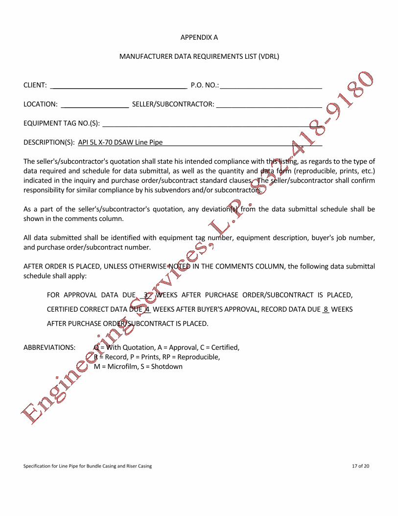
APPENDIX A
MANUFACTURER DATA REQUIREMENTS LIST (VDRL) CLIENT: ___________________________________ P.O. NO.:___________________________ LOCATION: _________________ SELLER/SUBCONTRACTOR: ____________________________ EQUIPMENT TAG NO.(S): __________________________________________________________ DESCRIPTION(S): API 5L X‐70 DSAW Line Pipe__________________________________________ The seller's/subcontractor's quotation shall state his intended compliance with this listing, as regards to the type of data required and schedule for data submittal, as well as the quantity and data form (reproducible, prints, etc.) indicated in the inquiry and purchase order/subcontract standard clauses. The seller/subcontractor shall confirm responsibility for similar compliance by his subvendors and/or subcontractors. As a part of the seller's/subcontractor's quotation, any deviation(s) from the data submittal schedule shall be shown in the comments column. All data submitted shall be identified with equipment tag number, equipment description, buyer's job number, and purchase order/subcontract number. AFTER ORDER IS PLACED, UNLESS OTHERWISE NOTED IN THE COMMENTS COLUMN, the following data submittal schedule shall apply:
FOR APPROVAL DATA DUE 3 WEEKS AFTER PURCHASE ORDER/SUBCONTRACT IS PLACED,
CERTIFIED CORRECT DATA DUE 4 WEEKS AFTER BUYER'S APPROVAL, RECORD DATA DUE 8 WEEKS
AFTER PURCHASE ORDER/SUBCONTRACT IS PLACED.
ABBREVIATIONS: Q = With Quotation, A = Approval, C = Certified,
R = Record, P = Prints, RP = Reproducible, M = Microfilm, S = Shotdown

Specification for Line Pipe for Bundle Casing and Riser Casing 18 of 20
MANUFACTURER DATA REQUIREMENTS LIST (VDRL) Data Data Required Code Data Description/Definition Q A C R Comments
MANUFACTURER Data Schedule 3P 6P
Production Schedule 3P 6P 6P
QA/QC Plan 3P 6P 6P
Manufacturing Procedure Specification 3P 6P 6P
Internal Pressure Test Certificate, Records and Report 6P
Heat Treatment Records Date/Time/Check Off Chart 6P
Mill Test Certificate including 6P Mechanical and Chemical Composition Tests
Proposed Chemical Composition 6P 6P 6P
Non‐Conformity Reports 6P
Welding Procedure Specifications 6P
Procedure Qualification Records 6P
Welder Performance Qualifications Records 6P
Weld Repair Procedures 6P
Weld Repair Procedures Qualifications Resumes 6P
Tallies 6P
Individual Joint Weight 6P
Inspection Reports including Daily NDE Reports (all methods) and Dimension Check Results 6P
Specification for Line Pipe for Bundle Casing and Riser Casing 19 of 20
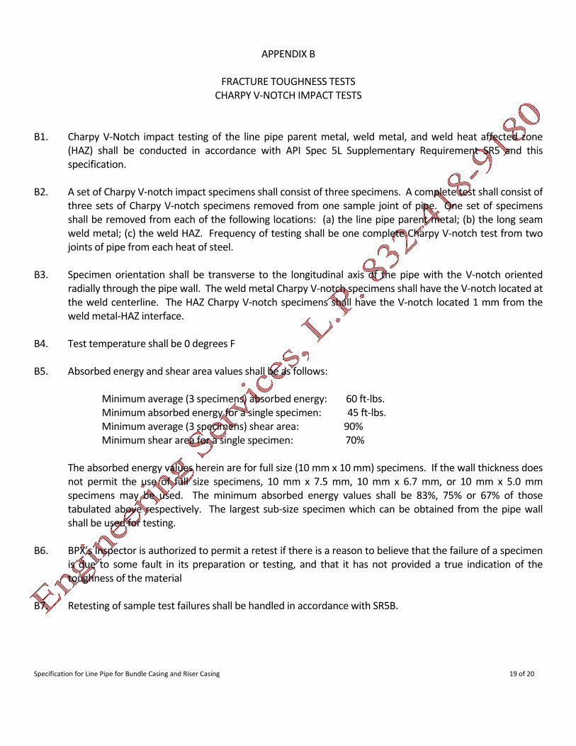
APPENDIX B
FRACTURE TOUGHNESS TESTS CHARPY V‐NOTCH IMPACT TESTS
B1. Charpy V‐Notch impact testing of the line pipe parent metal, weld metal, and weld heat affected zone
(HAZ) shall be conducted in accordance with API Spec 5L Supplementary Requirement SR5 and this specification.
B2. A set of Charpy V‐notch impact specimens shall consist of three specimens. A complete test shall consist of
three sets of Charpy V‐notch specimens removed from one sample joint of pipe. One set of specimens shall be removed from each of the following locations: (a) the line pipe parent metal; (b) the long seam weld metal; (c) the weld HAZ. Frequency of testing shall be one complete Charpy V‐notch test from two joints of pipe from each heat of steel.
B3. Specimen orientation shall be transverse to the longitudinal axis of the pipe with the V‐notch oriented
radially through the pipe wall. The weld metal Charpy V‐notch specimens shall have the V‐notch located at the weld centerline. The HAZ Charpy V‐notch specimens shall have the V‐notch located 1 mm from the weld metal‐HAZ interface.
B4. Test temperature shall be 0 degrees F B5. Absorbed energy and shear area values shall be as follows:
Minimum average (3 specimens) absorbed energy: 60 ft‐lbs. Minimum absorbed energy for a single specimen: 45 ft‐lbs. Minimum average (3 specimens) shear area: 90% Minimum shear area for a single specimen: 70%
The absorbed energy values herein are for full size (10 mm x 10 mm) specimens. If the wall thickness does
not permit the use of full size specimens, 10 mm x 7.5 mm, 10 mm x 6.7 mm, or 10 mm x 5.0 mm specimens may be used. The minimum absorbed energy values shall be 83%, 75% or 67% of those tabulated above respectively. The largest sub‐size specimen which can be obtained from the pipe wall shall be used for testing.
B6. BPX’s Inspector is authorized to permit a retest if there is a reason to believe that the failure of a specimen
is due to some fault in its preparation or testing, and that it has not provided a true indication of the toughness of the material
B7. Retesting of sample test failures shall be handled in accordance with SR5B.

Specification for Line Pipe for Bundle Casing and Riser Casing 20 of 20
APPENDIX C
MANUFACTURER’S QA/QC PLAN REQUIREMENTS C1. Before work begins, MANUFACTURER shall submit to COMPANY and receive written approval for, a Quality
plan and QA/QC procedures for carrying out the work according to this specification and the purchase order, including but not limited to the following:
a) Organization description; b) Quality control and inspection procedures, including procedures for identifying, documenting, and
segregating or disposing of non‐conforming materials; c) Description of personnel qualification for performing the verification activities; d) Methods employed to obtain homogeneous plate quality and method of plate forming; e) Welding procedure including method, speed of welding and welding electrical characteristics; f) UT procedure for plate, welds g) Radiography procedure h) Weld procedure i) Method of straightening, sizing, and hydrostatic testing; j) Method of measuring and controlling pipe straightness and end squareness; k) Description of bevel protectors; l) Procedures for maintaining heat and lot identity of all pipe, as required under Section SR15.2 of API
SPEC 5L; m) A description of the format and information to be included on the required reports, described in
Section 14.2 and elsewhere in this specification; n) Method of accurately weighing pipes.
In addition, the Quality Plan should also include a list of specific attributes and activities subject to verification, frequency of verification, acceptance criteria, and reporting and documentation requirements.


