
ERGON ENERGY CORPORATION LIMITED
SPECIFICATION
FOR
DISTRIBUTION DESIGN DRAFTING STANDARD

Specification for Distribution Design Drafting Standard
Check this is the latest Process Zone version before use. i Specification RSD04 Ver 2
Ergon Energy Corporation Limited ABN 50 087 646 062 Ergon Energy Queensland Pty Ltd ABN 11 121 177 802
Table of Contents
PURPOSE AND SCOPE.............................................................................................1
RESPONSIBILITIES ...................................................................................................1
1. TYPES OF DISTRIBUTION & SUBTRANSMISSION DESIGNS.......................1
2. CONSTRUCTION PLAN....................................................................................1
3. EXPLANATION..................................................................................................2 3.1. Project Numbers.................................................................................................... 2 3.2. Standard Title Block .............................................................................................. 2 3.3. Revised Construction Plan .................................................................................... 2 3.4. Standard Notes...................................................................................................... 3 3.5. Work Specific Notes .............................................................................................. 3 3.6. Conduit Schematic Diagrams (where applicable).................................................. 3 3.7. Location Map......................................................................................................... 4 3.8. Standard Drawing Sheets...................................................................................... 4 3.9. Smallworld Footprint.............................................................................................. 4 3.10. Standard Scales .................................................................................................... 4 3.11. North Sign Standard Symbol ................................................................................. 4 3.12. Design Approval Check ......................................................................................... 4 3.13. Design Approval Matrix ......................................................................................... 5
4. CONDUIT CONSTRUCTION PLAN ..................................................................5 4.1. Standard Format.................................................................................................... 5 4.2. Sample Construction Plan ..................................................................................... 6
5. UNDERGROUND CONSTRUCTION PLAN ......................................................6 5.1. Standard Format.................................................................................................... 6 5.2. Sample Construction Plan ..................................................................................... 6
6. OVERHEAD CONSTRUCTION PLAN...............................................................7 6.1. Standard Format.................................................................................................... 7 6.2. Sample Construction Plan ..................................................................................... 7
7. STREET LIGHT CONSTRUCTION PLAN .........................................................7 7.1. Standard Format.................................................................................................... 7 7.2. Sample Construction Plan ..................................................................................... 8
8. SCHEDULES.....................................................................................................8 8.1. Sample Construction Plan ..................................................................................... 8 8.2. Construction Schedule ........................................................................................ 10

Specification for Distribution Design Drafting Standard
Check this is the latest Process Zone version before use. ii Specification RSD04 Ver 2
Ergon Energy Corporation Limited ABN 50 087 646 062 Ergon Energy Queensland Pty Ltd ABN 11 121 177 802
Purpose............................................................................................................................. 11 8.3. Overhead Conductor Schedule ........................................................................... 13 Purpose............................................................................................................................. 14 8.4. Public Lighting Schedule ..................................................................................... 15 Purpose............................................................................................................................. 16 8.5. Underground Cable Schedule ............................................................................. 17 Purpose............................................................................................................................. 18 8.6. Conduit Ducting Schedule ................................................................................... 19 Purpose............................................................................................................................. 20
APPENDIX A – TITLE BLOCK..................................................................................21
APPENDIX B – SYSTEM DESIGNER – FIELD MEASUREMENT GUIDELINES.....22
APPENDIX C – SYMBOLOGY..................................................................................22

Specification for Distribution Design Drafting Standard
Check this is the latest Process Zone version before use. Page 1 of 22 Specification RSD04 Ver 2
Ergon Energy Corporation Limited ABN 50 087 646 062 Ergon Energy Queensland Pty Ltd ABN 11 121 177 802
PURPOSE AND SCOPE To describe a minimum set of standards to be adhered to by Ergon Energy Line Design staff and External Designers for the production of a construction plan associated with the development and or maintenance of the distribution network. The standard format included in this standard has been developed for use on distribution construction plans and agreed to by the Mapping & Design Operational Forum. All future amendments to this standard are to be presented to the Forum for consideration. The need for standardisation is driven by the following business requirements:
A standard format is necessary for training purposes; A standard format can be understood by all Ergon Energy Line Design and
Construction staff who may be required to work across all regions; A standard format is required by Contractors and Consultants who may work across all
regions. This document details the required standard format for construction plan presentation to Constructors, both internal and external. It does not attempt to stipulate standard design or construction processes or practices.
RESPONSIBILITIES Manager Line Standards is the Approver listed in MI000403R100. Process Owners & Sub-Process Managers List (Reference). Design & Connection Services Manager shall maintain this Specification document.
Design Standards Coordinator is the Subject Matter Expert (SME) for this Specification document.
1. TYPES OF DISTRIBUTION & SUBTRANSMISSION DESIGNS This standard applies to the presentation of the following designs:
• All overhead network distribution designs up to and including 66kV; • All underground network distribution designs up to and including 66kV; • All public lighting designs for the lighting layout design.
2. CONSTRUCTION PLAN A ‘construction plan’ is prepared for all additions and alterations to the Distribution & Sub Transmission Network. A construction plan provides a structured and consistent presentation of information required for estimating, construction, statutory approvals and asset identification for updating of the GIS and subsequently Ellipse – Asset Management Program. The following construction plans are detailed:
• Overhead electrical reticulation • Underground electrical reticulation • Conduit Plan required for the installation of underground conduit and associated works • Street Lighting.
Hard copies are to be printed in colour for clarity.

Specification for Distribution Design Drafting Standard
Check this is the latest Process Zone version before use. Page 2 of 22 Specification RSD04 Ver 2
Ergon Energy Corporation Limited ABN 50 087 646 062 Ergon Energy Queensland Pty Ltd ABN 11 121 177 802
3. EXPLANATION
3.1. Project Numbers The Ellipse Work Request Number for each project is to be used to register a construction plan and the following format is to be used - 12345.
3.2. Standard Title Block The title block of a construction plan provides information for identification of the proposed works and status of the construction plan. The title block should be placed at the bottom of the construction plan and the format depicted in Appendix A is recommended. Mandatory information to be included by Designer:
• Project Number • Sheet size • Scale • Issue • Description standard format:
• Location of project • Description of work – and type of plan e.g. ‘Conduit Construction Plan’ • Customer’s details
• Reference drawings • Construction plan revisions • ‘As Constructed’ Stamp (refer below for example of stamp)
ON COMPLETION, MARK UP THIS PRINT CLEARLY WITH ALL FINAL
CHANGES AND RETURN TO NETWORKDATA GROUP FOR REGION
CHANGES Yes/No
COMPLETION DATE……………………….
PRINT NAME………………………………
POSITION……………………………………
SIGNATURE…………………………………
DATE…………………………………………
3.3. Revised Construction Plan For Energy Services, the Designer must be consulted about all required changes to the construction plan. The Designer will perform a design check to determine if the requested change will alter either of the structural/civil, technical design or lighting design. If it does, this will be a major change; however, if it doesn’t alter the design, it is a minor change.

Specification for Distribution Design Drafting Standard
Check this is the latest Process Zone version before use. Page 3 of 22 Specification RSD04 Ver 2
For a major change a new revision of the construction plan is to be issued but for a minor change a verbal approval will be followed up with an email confirmation.
NB. All approved changes to the Construction Plan are to be marked up in RED, in a neat and legible manner allowing the amendments to be clearly understood.
3.4. Standard Notes The Mapping and Design Forum have approved a standard set of notes to be included on construction plans. They are located on the shared drive \\ecasd01\smallworld\Standardnotes - these are to be copied and pasted to the construction plan.
Requests for additional notes or modification to existing notes are to be approved by the Mapping and Design forum, the Design Support Co-ordinator and the Senior Design Support Officer shall have administration rights to this folder.
3.5. Work Specific Notes Work Specific Notes are notes/instructions that are necessary to highlight particular high risk features within the construction plan. These are to be large enough to be clearly visible and easily attract the attention of construction staff. The boxes should be located as close as practical, and with an arrow pointing to the affected site.
Example: Caution and Warning flags indicating possible conflict with other utilities’ major assets – to be in a RED text box with a pointer and with black text.
Ergon Energy Corporation Limited ABN 50 087 646 062 Ergon Energy Queensland Pty Ltd ABN 11 121 177 802
WARNING Telstra Optic Fibre Cable
on 4.0m alignment – Contact Joe Bloggs for physical location phone
46532187
3.6. Conduit Schematic Diagrams (where applicable) Conduit Schematic Diagrams are to be geographical and include the following objects:
• Ducts• Station numbers• Padmount transformer (if allocated)• HV Isolating Devices (if required)• Termination pole or existing asset• Pillars• Pits (if required)• Street Lights
Cadastre information is not required.

Specification for Distribution Design Drafting Standard
Check this is the latest Process Zone version before use. Page 4 of 22 Specification RSD04 Ver 2
3.7. Location Map If required, a Location Map can be included as a separate sheet or as an inset on the construction plan.
3.8. Standard Drawing Sheets The Drawing Sheets are limited to the following sizes:
• A1 Landscape • A2 Landscape • A2 Portrait • A3 Landscape • A4 Landscape • A4 Portrait
3.9. Smallworld Footprint All footprints should be reviewed and updated to encompass only the work area required with a suggested additional 50m buffer for rural and 10m buffer for urban.
3.10. Standard Scales The Standard Scales are:
• 1:500 • 1:750 • 1:1000 • 1:1250 • 1:1500 • 1:2000 • 1:2500 • 1:3000 for large OH, UG or Comms works plan • 1:4000 for large OH, UG or Comms works plan • 1:5000 for large OH, UG or Comms works plan • 1:10000 for large OH, UG or Comms works plan • 1:20000 • 1:25000
3.11. North Sign Standard Symbol
3.12. Design Approval Check The approver of all Smallworld designs must check the design against this document for compliance to the standard.
Ergon Energy Corporation Limited ABN 50 087 646 062 Ergon Energy Queensland Pty Ltd ABN 11 121 177 802
Specification for Distribution Design Drafting Standard
Check this is the latest Process Zone version before use. Page 5 of 22 Specification RSD04 Ver 2
Ergon Energy Corporation Limited ABN 50 087 646 062 Ergon Energy Queensland Pty Ltd ABN 11 121 177 802
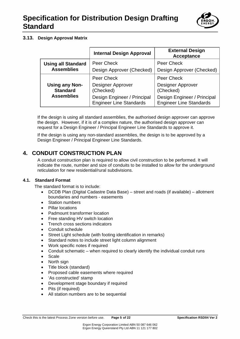
3.13. Design Approval Matrix
Internal Design Approval External Design Acceptance
Using all Standard Assemblies
Peer Check Design Approver (Checked)
Peer Check Design Approver (Checked)
Using any Non-Standard
Assemblies
Peer Check Designer Approver (Checked) Design Engineer / Principal Engineer Line Standards
Peer Check Designer Approver (Checked) Design Engineer / Principal Engineer Line Standards
If the design is using all standard assemblies, the authorised design approver can approve the design. However, if it is of a complex nature, the authorised design approver can request for a Design Engineer / Principal Engineer Line Standards to approve it.
If the design is using any non-standard assemblies, the design is to be approved by a Design Engineer / Principal Engineer Line Standards.
4. CONDUIT CONSTRUCTION PLAN A conduit construction plan is required to allow civil construction to be performed. It will indicate the route, number and size of conduits to be installed to allow for the underground reticulation for new residential/rural subdivisions.
4.1. Standard Format The standard format is to include:
• DCDB Plan (Digital Cadastre Data Base) – street and roads (if available) – allotment boundaries and numbers - easements
• Station numbers • Pillar locations • Padmount transformer location • Free standing HV switch location • Trench cross sections indicators • Conduit schedule • Street Light schedule (with footing identification in remarks) • Standard notes to include street light column alignment • Work specific notes if required • Conduit schematic – when required to clearly identify the individual conduit runs • Scale • North sign • Title block (standard) • Proposed cable easements where required • ‘As constructed’ stamp • Development stage boundary if required • Pits (if required) • All station numbers are to be sequential

Specification for Distribution Design Drafting Standard
Check this is the latest Process Zone version before use. Page 6
Ergon Energy Corporation LimErgon Energy Queensland Pt
4.2. Sample Construction Plan The following sample construction plan is included to illustrate as closely as possible the correct completion of schedules and construction plan format: If the link to the embedded document is broken please request a copy of the sample construction plan.
5. UNDERGROUND CONSTRUCTION
5.1. Standard Format The standard format is to include:
• DCDB Plan (Digital Cadastre Data Base) – boundaries and numbers - easements
• Station numbers • Pillar locations • Padmount transformer location (if required) • Free standing HV switch location (if required• Schedules (as per Section 8)
• Construction Schedule • Underground Cable Schedule • Public Lighting Schedule • Conduit Ducting Schedule
• Standard notes as required • Work specific notes as required • Scale • North sign • Title block (standard) • Proposed cable easements • ‘As constructed’ stamp • Development stage boundary • Zone substation number • Feeder number • Indicate relevant phase for each lot – R, W • Location map as required • Cable Joints • All station numbers are to be sequential
5.2. Sample Construction Plan The following sample construction plan is includedcompletion of schedules and construction plans for
of 22 Specification RSD04 Ver 2
ited ABN 50 087 646 062 y Ltd ABN 11 121 177 802
PLAN
street and roads (if available) allotment
)
or B
to illustrate as closely as possible the correct mat:

Specification for Distribution Design Drafting Standard
Check this is the latest Process Zone version before use. Page 7 of 22 Specification RSD04 Ver 2
Ergon Energy Corporation Limited ABN 50 087 646 062 Ergon Energy Queensland Pty Ltd ABN 11 121 177 802
If the link to the embedded document is broken please request a copy of the sample construction plan.
6. OVERHEAD CONSTRUCTION PLAN An Overhead construction plan is prepared for the erection of overhead electrical reticulation.
6.1. Standard Format The standard format is to include:
• DCDB Plan (Digital Cadastre Data Base) – street and roads (if available) – allotment boundaries and numbers - easements
• Station numbers • Pole Locations • Schedules (as per Section 8)
• Construction Schedule • Overhead Conductor Schedule • Public Lighting Schedule
• Standard notes as required • Work specific notes as required • Scale • North sign • Title block (standard) • Zone substation number • Feeder number • Location map if required • Span lengths – (Note: span lengths shown in Smallworld may not be true due to
cadastre shift) • All station numbers are to be sequential
6.2. Sample Construction Plan The following sample construction plans are included to illustrate as closely as possible the correct completion of schedules and construction plan format: If the link to the embedded document is broken please request a copy of the sample construction plan.
7. STREET LIGHT CONSTRUCTION PLAN A Streetlight Construction Plan is prepared for erection/ installation of public lighting.
7.1. Standard Format The standard format is to include:
• DCDB Plan (Digital Cadastre Data Base) – street and roads (if available) – allotment boundaries and numbers - easements
• Station numbers • Pole Locations

Specification for Distribution Design Drafting Standard
Check this is the latest Process Zone version before use. Page 8 of 22 Specification RSD04 Ver 2
Ergon Energy Corporation Limited ABN 50 087 646 062 Ergon Energy Queensland Pty Ltd ABN 11 121 177 802
• Schedules (as per Section 8) • Construction Schedule • Overhead Conductor Schedule • Public Lighting Schedule
• Standard notes as required • Work specific notes as required • Scale • North sign • Title block (standard) • Zone substation number • Feeder number • Location map if required • ‘As Constructed’ stamp • A statement of Compliance with the requirements of AS/NZ 1158 (in accordance with
AS/NZS 158.1.1:2005 Clause 2.11 and Appendix D) • All station numbers are to be sequential
7.2. Sample Construction Plan The following sample construction plan is included to illustrate as closely as possible the correct completion of schedules and construction plan format: If the link to the embedded document is broken please request a copy of the sample construction plan.
8. SCHEDULES
8.1. Sample Construction Plan Schedules provide an ordered layout of information relevant to any modification to the Energy Services network. Schedules are to accompany all construction plans. It is preferable that the construction plan and its associated schedules be presented on the same sheet. If this is not practical, then schedules may be grouped on a separate sheet. Data entered onto schedules to be limited to one item per line, for each column. Modification of the schedules is permitted but limited to turning off columns that do not contain data, from being displayed within the drawing. This is the default setting. Schedule font size is free text, default settings:
• Schedule data text 2mm; • Schedule column heading text 1.8mm; • Schedule title 137% of column heading text.
The schedule headings word-wrap as standard default. The following schedules are detailed, including definitions for column entries:
• Construction Schedule – applicable to OH and UG works including distribution substations. • Overhead Conductor Schedule – applicable to OH conductor works, including LV Services. • Public Lighting Schedule – applicable to all public lighting works, excluding watchman
lighting. • Underground Cable Schedule – applicable to all underground cabling activities.

Specification for Distribution Design Drafting Standard
Check this is the latest Process Zone version before use. Page 9 of 22 Specification RSD04 Ver 2
Ergon Energy Corporation Limited ABN 50 087 646 062 Ergon Energy Queensland Pty Ltd ABN 11 121 177 802
• Conduit Ducting Schedule – applicable for all runs of underground conduits, including bends where required.

Specification for Distribution Design Drafting Standard
Check this is the latest Process Zone version before use. Page 10 of 22 Specification RSD04 Ver 2
Ergon Energy Corporation Limited ABN 50 087 646 062 Ergon Energy Queensland Pty Ltd ABN 11 121 177 802
8.2. Construction Schedule
CONSTRUCTION SCHEDULE STN NO
SITE LABEL
POLE ALIGNMENT
POLE SETTING DEPTH
ACTION CONSTRUCTION CLASS
CONSTRUCTION CODE
DRAWING NUMBER
POSITION ON POLE
REMARKS
Specification for Distribution Design Drafting Standard
Check this is the latest Process Zone version before use. Page 11 of 22 Specification RSD04 Ver 2
Ergon Energy Corporation Limited ABN 50 087 646 062 Ergon Energy Queensland Pty Ltd ABN 11 121 177 802
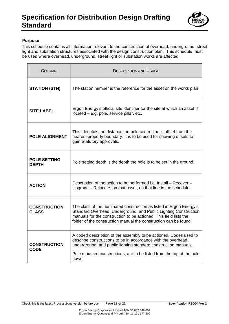
Purpose This schedule contains all information relevant to the construction of overhead, underground, street light and substation structures associated with the design construction plan. This schedule must be used where overhead, underground, street light or substation works are affected.
COLUMN DESCRIPTION AND USAGE
STATION (STN) The station number is the reference for the asset on the works plan
SITE LABEL Ergon Energy’s official site identifier for the site at which an asset is located – e.g. pole, service pillar, etc.
POLE ALIGNMENT This identifies the distance the pole centre line is offset from the nearest property boundary. It is to be used for showing offsets to gain Statutory approvals.
POLE SETTING DEPTH Pole setting depth is the depth the pole is to be set in the ground.
ACTION Description of the action to be performed i.e. Install – Recover – Upgrade – Relocate, on that asset, on that line in the schedule.
CONSTRUCTION CLASS
The class of the nominated construction as listed in Ergon Energy’s Standard Overhead, Underground, and Public Lighting Construction manuals for the construction to be actioned. This field lists the folder of the construction manual the construction can be found.
CONSTRUCTION CODE
A coded description of the assembly to be actioned. Codes used to describe constructions to be in accordance with the overhead, underground, and public lighting standard construction manuals.
Pole mounted constructions, are to be listed from the top of the pole down.

Specification for Distribution Design Drafting Standard
Check this is the latest Process Zone version before use. Page 12 of 22 Specification RSD04 Ver 2
Ergon Energy Corporation Limited ABN 50 087 646 062 Ergon Energy Queensland Pty Ltd ABN 11 121 177 802
COLUMN DESCRIPTION AND USAGE
DRAWING NUMBER
This is the drawing number in the overhead, underground and lighting standard construction manuals for the nominated construction.
POSITION ON POLE
This is the order in which the nominated constructions are added to the pole. The position 1 is at the head of the pole and subsequent numbers move the constructions down the pole.
REMARKS
To be utilised for construction notes only. Details of all constructions to be worked on are to be detailed in the construction column. These remarks are being stored against each object and auto populated into the schedule.

Specification for Distribution Design Drafting Standard
Check this is the latest Process Zone version before use. Page 13 of 22 Specification RSD04 Ver 2
Ergon Energy Corporation Limited ABN 50 087 646 062 Ergon Energy Queensland Pty Ltd ABN 11 121 177 802
8.3. Overhead Conductor Schedule
OVERHEAD CONDUCTOR SCHEDULE STN
FROM STN TO ACTION VOLTAGE CONDUCTOR
CODE NUMBER OF
CONDUCTORSROUTE
LENGTH (m)
MES (M) %NBL WIND
PRESSURE (pa)
REMARKS

Specification for Distribution Design Drafting Standard
Check this is the latest Process Zone version before use. Page 14 of 22 Specification RSD04 Ver 2
Ergon Energy Corporation Limited ABN 50 087 646 062 Ergon Energy Queensland Pty Ltd ABN 11 121 177 802
Purpose This schedule contains all information relevant to the design, construction and recording of work on overhead conductors associated with the works plan. This schedule must be used when overhead conductors are affected by the works.
COLUMN DESCRIPTION AND USAGE
STN FROM The works plan station numbers at which a particular strain section commences. A separate line is to be used for each strain section as indicated on the works plan.
STN TO The works plan station numbers at which a particular strain section terminates. A separate line is to be used for each strain section as indicated on the works plan.
ACTION Description of the action to be performed on the conductors on the same line in the schedule.
VOLTAGE The nominal voltage type of the conductors. e.g. 11 kV, LV.
CONDUCTOR CODE
A description of the conductors or cables to be worked on. The conductor code is listed. Refer to the Energy Services Design manual – Standard Conductor Applications Dwg 3053 sheet 2.
ROUTE LENGTH The sum of the span lengths between station numbers in metres.
NUMBER OF CONDUCTORS
This is the number of individual conductors that make up the each run of mains between the nominated station numbers.
MES Mean effective span in metres as calculated in accordance with the Design Manual, for the spans in a single strain section between the nominated station numbers.
%NBL Percentage Nominal Breaking Load. The design tension limit which is not to be exceeded under the specified loading conditions.
WIND PRESSURE This is the wind pressure in Pascals to which the conductor stringing calculations were performed.
REMARKS To be utilised for construction notes only. Details of all conductors to be worked on are to be detailed in the conductor column.

Specification for Distribution Design Drafting Standard
Check this is the latest Process Zone version before use. Page 15 of 22 Specification RSD04 Ver 2
Ergon Energy Corporation Limited ABN 50 087 646 062 Ergon Energy Queensland Pty Ltd ABN 11 121 177 802
8.4. Public Lighting Schedule
PUBLIC LIGHTING SCHEDULE STN NO.
SITE LABEL ACTION CONSTRUCTION
CODE RATE OWNER MOUNTING HEIGHT ORIENTATION REMARKS
Specification for Distribution Design Drafting Standard
Check this is the latest Process Zone version before use. Page 16 of 22 Specification RSD04 Ver 2
Ergon Energy Corporation Limited ABN 50 087 646 062 Ergon Energy Queensland Pty Ltd ABN 11 121 177 802
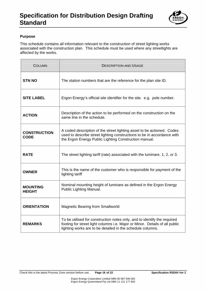
Purpose
This schedule contains all information relevant to the construction of street lighting works associated with the construction plan. This schedule must be used where any streetlights are affected by the works.
COLUMN DESCRIPTION AND USAGE
STN NO The station numbers that are the reference for the plan site ID.
SITE LABEL Ergon Energy’s official site identifier for the site. e.g. pole number.
ACTION Description of the action to be performed on the construction on the same line in the schedule.
CONSTRUCTION CODE
A coded description of the street lighting asset to be actioned. Codes used to describe street lighting constructions to be in accordance with the Ergon Energy Public Lighting Construction manual.
RATE The street lighting tariff (rate) associated with the luminare. 1, 2, or 3.
OWNER This is the name of the customer who is responsible for payment of the lighting tariff
MOUNTING HEIGHT
Nominal mounting height of luminare as defined in the Ergon Energy Public Lighting Manual.
ORIENTATION Magnetic Bearing from Smallworld
REMARKS To be utilised for construction notes only, and to identify the required footing for street light columns i.e. Major or Minor. Details of all public lighting works are to be detailed in the schedule columns.

Specification for Distribution Design Drafting Standard
Check this is the latest Process Zone version before use. Page 17 of 22 Specification RSD04 Ver 2
Ergon Energy Corporation Limited ABN 50 087 646 062 Ergon Energy Queensland Pty Ltd ABN 11 121 177 802
8.5. Underground Cable Schedule
UNDERGROUND CABLE SCHEDULE STN
FROM STN TO ACTION VOLTAGE CONSTRUCTION
CODE ROUTE
LENGTH CABLE
LENGTH REMARKS

Specification for Distribution Design Drafting Standard
Check this is the latest Process Zone version before use. Page 18 of 22 Specification RSD04 Ver 2
Ergon Energy Corporation Limited ABN 50 087 646 062 Ergon Energy Queensland Pty Ltd ABN 11 121 177 802
Purpose This schedule contains all information relevant to the design, construction and recording works on underground cabling associated with the construction plan. This schedule must be used where any underground cabling is affected.
COLUMN DESCRIPTION AND USAGE
STN FROM The works plan station number at which the cable run is to commence.
STN TO The works plan station number at which the cable run is to terminate.
ACTION Description of the action to be performed on the construction on the same line in the schedule
VOLTAGE The nominal voltage type of the cables, e.g. 11 kV, LV.
CONSTRUCTION CODE A description of the cable size and type.
ROUTE LENGTH The total length of cable as measured off the plan between terminations , etc.
CABLE LENGTH The total length of cable required including allowance for end lengths (terminations, joints) etc.
REMARKS To be utilised for construction notes only, including proposed HV joint locations. Details of all underground cabling works are to be detailed in the schedule columns.

Specification for Distribution Design Drafting Standard
Check this is the latest Process Zone version before use. Page 19 of 22 Specification RSD04 Ver 2
Ergon Energy Corporation Limited ABN 50 087 646 062 Ergon Energy Queensland Pty Ltd ABN 11 121 177 802
8.6. Conduit Ducting Schedule
CONDUIT DUCTING SCHEDULE
STN FROM
STN TO ACTION
CONSTRUCTION CODE
LENGTH (m)
BENDS
REMARKS

Specification for Distribution Design Drafting Standard
Check this is the latest Process Zone version before use. Page 20 of 22 Specification RSD04 Ver 2
Ergon Energy Corporation Limited ABN 50 087 646 062 Ergon Energy Queensland Pty Ltd ABN 11 121 177 802
Purpose This schedule contains all information relevant to the laying of conduit ducts in trenches for underground works. This schedule shall be used for all underground construction plans. The station numbers are the sites the conduits run between. These sites include, • Poles • Pillars • Distribution Cabinets • Joints/end cap • Pits • Ground Mounted Switches (GMS) • Towers
COLUMN DESCRIPTION AND USAGE
STN FROM The works plan station number at which the conduit run is to commence.
STN TO The works plan station number at which the conduit run is to terminate.
ACTION Description of the action to be performed i.e. Install - Recover – Upgrade – Relocate, on the asset, on the same line in the schedule.
CONSTRUCTION CODE
A coded description of the assembly to be actioned. Codes used to describe constructions to be in accordance with the overhead, underground, and public lighting standard construction manuals.
LENGTH The length of the duct run between the nominated station numbers
BENDS This is a text field and information to be inserted manually, where required.
REMARKS To be utilised for construction notes only. Details of all civil works are to be detailed in the schedule columns.

Specification for Distribution Design Drafting Standard
Check this is the latest Process Zone version before use. Page 21 of 22 Specification RSD04 Ver 2
APPENDIX A – TITLE BLOCK The title block provides information on the identification of the proposed works, the Designer, the drawings status, the drawings approval information and the plan type. This style of title block is recommended. The project number itself must be located in a position where its identification maybe ascertained without unfolding the works plan, preferably at the bottom right hand corner. A title block is to be used on all works plans. The title block displayed has been reproduced from Ergon Energy’s standard drawing sheet template. Join A
AMEN
DM
ENTS
OA
OR
IGIN
AL
ISSU
E
Rev
B –
Stn
3 M
oved
2
met
re n
orth
7/9
/05
Works Plan revisions are to be noted here. Legend will be included in this section automatically by Smallworld
Join A
REFERENCE DRAWINGS Project Number: Drawing State:
ERGON ENERGY CORPORATION LTD Contract / Quote Number: Business Approved Date: Name:
Created Dat /Time: eCreated By: Check d Date: eName:
A1 SD01254
NEXT SHEET
11kV Windemere Feeder EB-D Innes Park Town Map Sheet 1 HV Schematic 9348/D-1
Approved Date: Approved By:
Perseverance Dam Road – Innes Park URD Subdivision – Electrical Plan Garrisha Pty Ltd Walker Family Trust SCALE: 1:2500
ISSUE
B
Ergon Energy Corporation Limited ABN 50 087 646 062 Ergon Energy Queensland Pty Ltd ABN 11 121 177 802

Specification for Distribution Design Drafting Standard
Check this is the latest Process Zone version before use. Page 22 of 22 Specification RSD04 Ver 2
Ergon Energy Corporation Limited ABN 50 087 646 062 Ergon Energy Queensland Pty Ltd ABN 11 121 177 802
APPENDIX B – SYSTEM DESIGNER – FIELD MEASUREMENT GUIDELINES The Designer responsible for the design and pegging of projects shall use a measuring instrument with a precision to enable all linear and angular measurements to be read with an accuracy that will ensure that the design will comply with all applicable Ergon Energy standards, policies and procedures. The accuracy of the selected instrument will be reflected by the complexities/ risk of the project.
APPENDIX C – SYMBOLOGY


FB
EA
AB
EA
FB
AA
FC
AA
BC
BC
AA
FC
AB
BB
GCGC
EA
FB
HB
GC
AA
FBEA
FB
AA
FB
FB
BB
AA
FB
BB
FB
AA
FA
FB
FB
AA
FB
BB BB
EA
AA
AA
AA
EA
EA
AB
EA
AB
EA
EA
ABEAAA
SUNNYRIDGE RO
AD
BOLE
S ST
REET
7
89
1011
5
4
3
62627
25
2829
24
23
14
2221
1213
1516
2019
18
17
2
139
3837
36
3031
3233
3435
4.00 m
12.4
3 m
3.21
m
8.47 m
25.5m 5.7m
7.54 m
12.13 m
33
32
34
31
30
61
62
27
5017
52
5164
28
76
5329
35
54
8
3
5
109
11
46
63
36
13
12
47
37
59
48
14
60
49
15
16
18
58 45
39
56
2
19
38
40
67
66
1
Unknown
4
65
20
21
42
41
26
2522
43
44
2324
57
SC200545
4032387
403531040349794035381
4034978 4034977
4034976
4034975
4034972
4034971
4034973
4034969
33
32
34
31
30
61
62
27
5017
52
5164
28
76 5329
35
54
8
35
109
11
4663
36
13
1247
37
59
48
14
60
49
15
16
18
58 45
39
56
2
19
38
40
67
66
1
465
20
2142
41
26
2522
43
44
2324
57
AB
GC
GC
EA
1 RP608950
2627
5164
28
7
65329
SC200545
BB
FB
HB
GC
AA
FB
FB
28
29
24
8
3
5
109
46
45
N
S
W E
1 2 3 4 5 6 7 8 9 10 11 12
H
G
F
E
D
C
A
B
A
B
C
D
E
F
G
H
COPYRIGHT This drawing must not be reproduced in part or whole without written permission from ERGON ENERGY CORPORATION Ltd.
A1
841 X 594UNLESS OTHERWISE STATEDALL DIMENSIONS IN MILLIMETRES
Contract / Quote Number Business Approved Date
Name:
Checked Date:
1 2 3 4 5 6 7 8 9 10 11 12
A1
ISSUE
ERGON ENERGY CORPORATION LTD
0m 20m 40m 60m
Name:
Project Number:
ABN 50 087 646 062
REFERENCE DRAWINGS
DRAWING REFERENCE No.B1 - 14G - 317/8
ZONE SUB/STN No. 07FEEDER No. GS-102
ELLIPSE FEEDER No. FD-1365 WET
PADMOUNT TRANSFORMER3.0m X 3.0m EASEMENT
CONDUIT SCHEMATIC
UNDERGROUND CONSTRUCTION NOTES
1. CONDUIT DEPTHS, ALIGNMENTS & TRENCHING detail refer Underground Construction Manual TRENCHING DWG5165. Provide Polymeric Cable Protection Cover in accordance with CONSTRUCTION PRACTICES DWG 5124.
2. Developer to supply and install conduits, lighti ng foundations, padmount foundation and site finish. Required Foundationconstruction for Padmount Transformer is code PMF11US. At si te 6, Lot 26 use the standard Padmount Uniculvert with baseslab as required in Ergon's specifications, CSR Humes P roduct No. 1 X Uniculvert, BC1200.9500 or Equiv., 2 X End Walls,BC1200.9510 or Equiv., & 1 X Base Sl ab, BC1200.0188 or Eqiuv.
Developer to provide a 3.0m X 3.0m Padmount Transformer easem ent in Lot 26, at site 6, & a 3.0m X 3.0m RMU easementin Lot 28, at site 5, as s hown on the drawing.
At site 5, a stand alone RMU culvert foundation will be required which is not shown in Ergon's URD Specifi cations, but detailswill be shown in Drawing No. 913095-01 to be supplied by the Designer & copies should be in the construc tion folders. The culvert foundation can be obtained from CS R Humes Rockham pton, Bryan Dobby 0419 476 132, Product No. 5104612is the 900 X 900 X 900 deep stormwater pit plus a specially m anufactured 100tk reinforced concrete lid for a 4 switch unit, isProduct No.5107632, to be provided wi th a 600 X 800 hole.Developer to install c able 35mm2 19/1.53 insulated copper to be direct buried in the trench with conduits between stations 5& 10 with enough length for connection at both ends. Cable to be suppli ed by Ergon.The cable should be connected to the common earth bar in the bottom of the RMU cabinet and to the LV MEN system whichwill generally be at the nearest pillar site.
3. Developer to contact Ergon Energy for site audits in acc ordance with RSC07.
4. Local council to accept streetlights and positions.
SPECIFICATIONS
This works plan is to be read in conjunction with the following ERGON ENERGY manuals and specifications.* RSC06 URD Main Specification* RSC07 URD Civil Works* Underground Construction Manual* Lighting Construction ManualConsumer's installation shall comply with AS3000: 1991 - SAA Wiring Rules.
RMU 3.0m X 3.0m EASEMENT
0m 5m 10m 15m 20m
0m 5m 10m 15m 20m 25m
CONDUIT SCHEMATIC PLAN
SHEET1 of 103/12/2007 10:01:20
ncrosbie
03/12/2007 13:00:54
jhope
ON COMPLETION, MARK UP THISPRINT CLEARLY WITH ALL FINALCHANGES AND RETURN TO NETWORKDATA GROUP FOR REGIONCHANGES Yes/No ………………COMPLETION DATE……………………….NAME…………………………………………POSITION……………………………………SIGNATURE…………………………………DATE…………………………………………
OR
IGIN
AL
ISS
UE
AM
EN
DM
EN
TS
OA
.
SCALE - 1:1000
SCALE 1:1000
Approved By:
Approved Date:
Created By: wwilson
Drawing Status: Investigate
E
Boles Street - Gladstone - URD Subdivis ion - The Glen Precinct stage 1 - URD Construction Plan - Foreman, OF TB No.1 Pty Ltd
Created Date/Time: 26/07/2007 16:38:06
CPMCY02580
LEGEND
DCDBLand Parcel - STATE LANDLand Parcel - FREEHOLDLand Parcel - RESERVE
Unregistered PropertyURP CloakURP KerbsURP LotsURP Roundabouts
ElectricityAerial Stay - as constructed
Connection Poi nt - Unknown PlannedDuct - planned
Earth - as constructedEarth - planned
Earth Cable - plannedEarth CableGMS Site
Pillar - Cross Road Pillar PlannedPillar - Normal Pillar Planned
Pole - HV/LVPole - Unknown PlannedPole - SL PlannedPole - HVPole - BollardPole - LVPole - LV Future HVPole - HV/LV Planned
Pole - LV Future HV ( To Be Removed)Pole - LV ( To Be Removed)Pole - Unknown ( To Be Removed)Pole - HV ( To Be Removed)
Pole - SL ( To Be Removed)Pole - HV/LV ( To Be Removed)Pole - Bollard ( To Be Removed)
Stay - as constructedStay - removed
Stay ( To Be Removed)
Streetlight - Column / Pole MountedStreetlight - Column / Pole Mounted PlannedStreetlight - PlannedStreetlight - Unknown
Substation - PlannedSubstation - Pole
Substation ( To Be Removed)
Low VoltageLV Cable - planned ( 240v)LV Cable - planned ( 415v)LV Cable Termination - planned ( 415v)
LV Line - as constructed ( 240v)LV Line - removed ( 240v)
LV Line - planned ( 240v)
LV Line - as constructed ( 415v)LV Line - removed ( 415v)LV Line - planned ( 415v)
LV Line - as constructed ( Streetlight)LV Line - removed ( Streetlight)LV Line - planned ( Streetlight)
LV Line ( To Be Removed)
LV Isolating Device - planned ( 240v)
LV Isolating Device - OpenBridge_planned ( 240v)
LV Isolating Device - planned ( 415v)LV Isolating Device - OpenBridge_planned ( 415v)
High VoltageHV Cable - planned ( 11kv)HV Cable Termination - planned ( 11Kv)
HV Line - as constructed ( 11kv)HV Line - removed ( 11kv)HV Line - planned ( 11kv)
HV Line ( To Be Removed)
Hv Isolating Device - removed ( 11Kv)Hv Isolating Device - planned ( 11Kv)
Hv Isolating Device - removed ( 22Kv)Hv Isolating Device - planned ( 22Kv)
Hv Isolating Device ( To Be Removed)
DraftingRedline Line (Path)
Conduit Schematic Legend
ElectricityDuct - 100mm/110mmDuct - 125mmDuct - 40mm
GMS Site
Streetlight - Column / Pole MountedStreetlight - Column / Pole Mounted PlannedStreetlight - PlannedStreetlight - Unknown
Pillar - Cross Road Pillar PlannedPillar - Normal Pillar Planned
Pole - HV/LVPole - Unknown Planned
Pole - SL PlannedPole - HVPole - BollardPole - LVPole - LV Future HVPole - HV/LV Planned
Pole - LV Future HV ( To Be Removed)Pole - LV ( To Be Removed)Pole - Unknown ( To Be Removed)Pole - HV ( To Be Removed)Pole - SL ( To Be Removed)Pole - HV/LV ( To Be Removed)Pole - Bollard ( To Be Removed)
Substation ( To Be Removed)
Conduit Ducting ScheduleSTN
FROMSTNTO
ACTION CONSTRUCTIONCODE
LENGTH(m)
REMARKS
4 9 Install C125L 139 m HV Conduit ends 1.5m f rom Pole 4 19 Install C100L 48 m LV Conduit 4 65 Install C40H 16 m Earth wire conduit to provide 15.0m
clearance from Telstra pit 7 8 Install C100L 59 m LV Conduit 7 9 Install C125L 78 m HV Conduit 7 17 Install C100L 74 m LV Conduit 7 27 Install C100L 21 m LV Conduit 8 10 Install C100L 22 m LV Conduit 9 33 Install C125L 177 m HV Conduit
10 11 Install C100L 40 m LV Conduit 10 16 Install C125L 161 m HV Conduit 10 46 Install C40H 3 m S/L Conduit 11 12 Install C100L 8 m LV Conduit 12 13 Install C100L 29 m LV Conduit 12 47 Install C40H 3 m S/L Conduit 13 14 Install C100L 42 m LV Conduit 13 48 Install C40H 25 m S/L Conduit 14 15 Install C100L 40 m LV Conduit 14 49 Install C40H 23 m S/L Conduit 17 18 Install C100L 25 m LV Conduit 17 45 Install C40H 3 m S/L Conduit 18 19 Install C100L 30 m LV Conduit 19 20 Install C100L 27 m LV Conduit 19 38 Install C40H 29 m S/L Conduit 19 39 Install C40H 8 m S/L Conduit 20 21 Install C100L 36 m LV Conduit 20 40 Install C40H 11 m S/L Conduit 20 41 Install C40H 12 m S/L Conduit 21 22 Install C100L 42 m LV Conduit 21 26 Install C100L 13 m LV Conduit 21 42 Install C40H 3 m S/L Conduit 22 23 Install C100L 45 m LV Conduit 22 25 Install C100L 13 m LV Conduit 22 43 Install C40H 4 m S/L Conduit 23 24 Install C100L 24 m LV Conduit 23 44 Install C40H 16 m S/L Conduit 27 50 Install C40H 3 m S/L Conduit 28 29 Install C100L 15 m LV Conduit 28 37 Install C100L 168 m LV Conduit X-press for futur e use to
Lots 13 & 14 28 37 Install C125L 168 m HV Conduit for futur e use to lots 49,
51, boundary of subdiv 29 30 Install C100L 23 m HV Conduit 30 31 Install C100L 38 m LV Conduit 30 35 Install C100L 42 m LV Conduit 30 51 Install C40H 9 m S/L Conduit 31 32 Install C100L 16 m LV Conduit 31 33 Install C100L 19 m LV Conduit 31 34 Install C100L 36 m LV Conduit 32 52 Install C40H 3 m S/L Conduit 35 36 Install C100L 41 m LV Conduit 35 53 Install C40H 16 m S/L Conduit 35 54 Install C40H 22 m S/L Conduit
Construction ScheduleSTNNO
SITELABEL
POLEALIGNMENT
POLESETTINGDEPTH
ACTION CONSTRUCTIONCLASS
CONSTRUCTIONCODE
DRAWINGNUMBER
POSITIONON POLE
REMARKS
1 Recover Pole Equipment 22FP3/5/MOO/U 1037 1 1 Recover Pole Equipment LVP3/50/000 1017 2 Conductor 4 X 7/.134AAC FLY 1 X19044 Recover Hv Isolating Device 11kV (DO) Unknown 3 20k EDO S/D markup L. Baker 2804/06 1 4034976 1.800 Recover Pole A51-23 Page 51 2 Recover Pole Equipment POLEEQUIPMENT Unknown 1 Post Processed 2 4201445 1.800 Recover Pole WP11/8D/NE 1091 3 Recover Pole Equipment POLEEQUIPMENT Unknown 1 Post Processed 3 Recover Stay STAY Unknown 2 3 152163 Recover Substation 50kVA 11kV/LV (SP) Unknown 3 3 118270.T1 Recover Transformer TRANSFORMER Unknown 4 3 4262117 2.000 Recover Pole WP12/8D/NE 1091 4 4034976 Install Pole WP14/8S/SB 1091 4 4034976 Install Pole Equipment 22TRS/MOO 1082 1 4 X019579 Install Hv Isolating Device CTP11TR185LPG3 1369 2 4 Install HV Cable Termination 11PM/CTC/ASL/185T 5206 3 4 4034976 Install Pole Equipment LVP3/50/000 1017 4 Conductor 4 X 7/.134AAC FLY 4 4034976 Install Pole Equipment SOHN/225/AL 1045 5 4 4034976 Install Pole Equipment SOHA/225/AL 1048 5 4 Install LV Cable Termination LVCTP/240/M/AL 5056 6 4 Install LV Isolating Device LVSWP/4/OW 5056 6 LV OPEN POINT 4 Install Earth EHVEMGMEN/SEP/AL 1446 7 5 X019580 Install Hv Isolating Device SPEC_HV_ISOL_DEV_UG Unknown RMU 4 X Feeder Switches (SafeLink
CCCC) B in No. 0105005 5 Install Earth EPM11/COM 5013 5 Install Earth EADDCU 5013 5 Install HV Cable Termination 11PM/CTC/ASL/185T 5206 5 Install HV Cable Termination 11PM/CTC/ASL/185T 5206 6 SC200545 Install Substation PM11/500/ASL2S1F 5191 6 Install Earth EADDCU 5013 6 Install Earth EPM11/COM 5013 6 Install HV Cable Termination 11PM/CTC/ASL/185T 5206 6 Install LV Cable Termination LVCTPM11/240 5087 6 Install LV Cable Termination LVCTPM11/240 5087 6 Install LV Cable Termination LVCTPM11/240 5087 7 Install Pillar LVPN2/6/240 5026 7 Install Earth EMEN/PIL 5085 8 Install Pillar LVPN2/6/240 5026 8 Install Earth EMEN/PIL 5085
10 Install Pillar LVPN2/6S/240 5026 10 Install Earth EMEN/PIL 5085 11 Install Pillar LVPN2/6/240 5026 11 Install Earth EMEN/PIL 5085 12 Install Pillar LVPN2/6S/240 5026 12 Install Earth EMEN/PIL 5085 13 Install Pillar LVPN2/6S/240 5026 13 Install Earth EMEN/PIL 5085 14 Install Pillar LVPN2/6S/240 5026 14 Install Earth EMEN/PIL 5085 15 Install Pillar LVPN1/6S/240 5025 15 Install Earth EMEN/PIL 5085 17 Install Pillar LVPN2/6S/240 5026 17 Install Earth EMEN/PIL 5085 18 Install Pillar LVPN2/6/240 5026 18 Install Earth EMEN/PIL 5085 19 Install Pillar LVPN3/6S/240 5027 Install additional S/L fuse A506-4 19 Install Earth EMEN/PIL 5085 20 Install Pillar LVPN2/6S/240 5026 Install additional S/L fuse A506-4 20 Install Earth EMEN/PIL 5085 21 Install Pillar LVPN2/6S/240 5026 21 Install Earth EMEN/PIL 5085 22 Install Pillar LVPN2/6S/240 5026 22 Install Earth EMEN/PIL 5085 23 Install Pillar LVPN2/6S/240 5026 23 Install Earth EMEN/PIL 5085 24 Install Pillar LVPN1/6/240 5025 24 Install Earth EMEN/PIL 5085 25 Install Pillar LVPX/6/16CU 5041 26 Install Pillar LVPX/6/16CU 5041 27 Install Pillar LVPX/6S/16CU 5041 29 Install Pillar LVPN2/6/240 5026 29 Install Earth EMEN/PIL 5085 30 Install Pillar LVPN3/6S/240 5027 30 Install Earth EMEN/PIL 5085 31 Install Pillar LVPN1/6S/240 5025 31 Install Earth EMEN/PIL 5085 32 Install Pillar LVPX/6S/16CU 5041 35 Install Pillar LVPN1/6S/240 5025 Install additional S/L fuse A506-4 35 Install Earth EMEN/PIL 5085 36 Install Pillar LVPX/6/16CU 5041 38 0.5600 Install Pole SLBPM/90/115/UGCI2 8038 Alignment from rear of kerb 39 0.5600 Install Pole SLBPM/90/115/UGCI2 8038 Alignment from rear of kerb 40 0.5600 Install Pole SLBPM/90/115/UGCI2 8038 Alignment from rear of kerb 41 0.5600 Install Pole SLBPM/90/115/UGCI2 8038 Alignment from rear of kerb 42 0.5600 Install Pole SLBPM/75/115CI 8042 Alignment from rear of kerb 43 0.5600 Install Pole SLBPM/75/115CI 8042 Alignment from rear of kerb 44 0.5600 Install Pole SLBPM/75/115CI 8042 Alignment from rear of kerb 45 0.5600 Install Pole SLBPM/75/115CI 8042 Alignment from rear of kerb 46 0.5600 Install Pole SLBPM/75/115CI 8042 Alignment from rear of kerb 47 0.5600 Install Pole SLBPM/75/115CI 8042 Alignment from rear of kerb 48 0.5600 Install Pole SLBPM/75/115CI 8042 Alignment from rear of kerb 49 0.5600 Install Pole SLBPM/75/115CI 8042 Alignment from rear of kerb 50 0.5600 Install Pole SLBPM/75/115CI 8042 Alignment from rear of kerb 51 0.5600 Install Pole SLBPM/75/115CI 8042 Alignment from rear of kerb 52 0.5600 Install Pole SLBPM/75/115CI 8042 Alignment from rear of kerb 53 0.5600 Install Pole SLBPM/75/115CI 8042 Alignment from rear of kerb 54 0.5600 Install Pole SLBPM/75/115CI 8042 Alignment from rear of kerb
SCALE 1:500
SCALE 1:500

FB
EA
AB
EA
FB
AA
FC
AA
BC
BC
AA
FC
AB
BB
GCGC
EA
FB
HB
GC
AA
FBEA
FB
AA
FB
FB
BB
AA
FB
BB
FB
AA
FA
FB
FB
AA
FB
BB BB
EA
AA
AA
AA
EA
EA
AB
EA
AB
EA
EA
ABEAAA
SUNNYRIDGE RO
AD
BO
LES
STR
EET
7
89
1011
5
4
3
62627
25
2829
24
23
14
2221
1213
1516
2019
18
17
2
139
3837
36
3031
3233
3435
33
32
34
31
30
61
62
27
5017
52
5164
28
76
5329
35
54
8
35
109
11
4663
36
13
1247
37
59
48
14
60
49
15
16
18
58 45
39
56
2
19
38
40
67
66
1Unknown
465
20
2142
41
26
2522
43
44
2324
57
SC200545
4032387
403531040349794035381
4034978 4034977
4034976
4034975
4034972
4034971
4034973
4034969
N
S
W E
1 2 3 4 5 6 7 8 9 10 11 12
H
G
F
E
D
C
A
B
A
B
C
D
E
F
G
H
COPYRIGHT This drawing must not be reproduced in part or whole without written permission from ERGON ENERGY CORPORATION Ltd.
A1
841 X 594UNLESS OTHERWISE STATEDALL DIMENSIONS IN MILLIMETRES
Contract / Quote Number Business Approved Date
Name:
Checked Date:
1 2 3 4 5 6 7 8 9 10 11 12
A1
ISSUE
ERGON ENERGY CORPORATION LTD
0m 20m 40m 60m
Name:
Project Number:
ABN 50 087 646 062
REFERENCE DRAWINGS
4
38
19
40
20
LV OPEN POINT
39
41
42
2621
22
25
43
23
24
44
18
17
45
46
47
48
13
14
49
15
36
27
50
728
30
51
3252
31
3334
3554
53
29
37LV SWITCH GEARTHE GLEN PRECINCTSC20054511/500/3
4034987
LEGENDOverhead LV LineU/G Conduit C100L + Cable LV- 240C4/673U/G Conduit C100L + Cable LV- 16CUC4/614U/G Conduit C40H+ Cable LV-6CUC2/507U/G Conduit C40H+ Cable LV- 16CUC2/603Conduit for future use
Street Light
Pillar Normal
Pillar Cross Road
LV SCHEMATIC
LOT 41RP610715
No. 71
No. 77
6
12
11
10
8
No. 75
No. 73 A
B
A
B
CA
C
B
C
A
B
C
BC
A
A
B
C
A
B
A
B
C
C
A
A
C
B
B
C
A
B
C
A
STAGE 1UNDERGROUND CONSTRUCTION NOTES
1. CONDUIT DEPTHS, ALIGNMENTS & TRENCHING detail refer Underground Construction Manua l TRENCHING DWG 5165. Provide Polymeri cCable Protection Cover in accordance with CONSTRUCTION PRACTICES DW G 5124.
2. Developer to supply and install conduits, lighti ng foundations, padmount foundation and site finish. Required Foundation construction forPadmount Transformer is code PM F11US. At site 6, Lot 26 use the standard Padmount Uniculvert with base slab as required in Ergon'sspecifications, CSR Humes P roduct No. 1 X Uniculvert, BC1200.9500 or Equiv., 2 X End Walls, BC1200.9510 or Equiv., & 1 X Base Slab,BC1200.0188 or Eqiuv. Developer to provide a 3.0m X 3.0m Padmount Transform er easement in Lot 26, at site 6, & a 3.0m X 3.0m RMU easem ent in Lot 28, at site 5, asshown on the drawing.At site 5, a stand alone RMU culvert foundation will be required which is not shown in Ergon's URD Specifications, but details wil l be shown inDrawing No. 913095-01 to be supplied by the Designer & copies should be in the constructi on folders. The culvert foundation can be obtained from CSR Humes Rock hampton, Bryan Dobby 0419 476 132, Product No. 5104612 is the 900 X 900 X900 deep stormwater pit plus a specially manufactured 100tk reinforced concrete lid for a 4 switc h unit, is Product No.5107632, to be provided witha 600 X 800 hole.Ergon to install cable 35mm2 19/1.53 insulated copper to be direct buri ed in the trench with conduits between stations 5 & 10 with enough length forconnection at both ends. The cable should be connected to the common earth bar in the bottom of the RMU cabinet and to the LV MEN system whic h will generally be at thenearest pillar site.
3. DBYD information to be provided in the construction folder. Physical l ocations for Council, Telstra, & Gas to be obtained where applicable.
4. Ergon Energy Civil Contractor to install conduits in road reserve accross Bol es Street, sites 4 to 56 as shown on plan. A C40H conduit is to beinstalled on the footpath from site 4, to a distance of 15.0m from the adjacent Telstra pit to provide cl earance & insulation for the HV equipmentearth as shown on the plan. Contractor Robert S haw mobile 0409783243.
5.Developer to contact Ergon Energy for site audits in acc ordance with RSC07.
6. Local council to accept streetlights and positions.
Asset Identification numbers to be glued or attached as required to all NEW HV & LV equipment & the numbers recorded against each relevant asset in the Construction Schedule includingPadmount Transformers. U/G Construction Manual - Assemblies - Dwg 568. O/H Construction Manual - Assemblies - Dwg 64.
X019579 TO X019580
X101 FOR FUTURE USE
X102 TO SC200545
X103 TO X019580
WARNINGHV Equipment Earth to be installed
in conduit from the pole to a distanceof 15.0m from the Telstra pit. The
Civil Contractor to install C40Hconduit to provide insulation for theearth wire to the position shown on
the plan.
X104 FOR FUTURE USE
X103 TO X019579
X102 FOR FUTURE USE
X101 TO SC200545
X019580
X104
X102
X103
X101
SC200545
X101
X102
X103
4034976
X019579
SITE LABELS
SITE 4 -
SITE 5 -
SITE 6 -
ON COMPLETION, MARK UP THISPRINT CLEARLY WITH ALL FINALCHANGES AND RETURN TO NETWORKDATA GROUP FOR REGIONCHANGES Yes/No ………………COMPLETION DATE……………………….NAME…………………………………………POSITION……………………………………SIGNATURE…………………………………DATE…………………………………………
03/12/2007 10:01:20
ncrosbie
03/12/2007 13:00:54
jhope
UNDERGROUND CONSTRUCTION PLAN
UNDERGROUND CONSTRUCTION
SPECIFICATIONS
This works plan is to be read in conjunction with thefollowing ERGON ENERGY manuals andspecifications.* RSC06 URD Main Specification* RSC07 URD Civil Works* Underground Construction Manual* Lighting Construction ManualConsumer's installation shall comply with AS3000:1991 - SAA Wiring Rules.
OVERHEAD CONSTRUCTION
SPECIFICATIONS
This works plan is to be read in conjunction with thefollowing ERGON ENERGY manuals andspecifications.* Distribution Field Manual* Overhead Construction Manual* Lighting Construction ManualConsumer’s installation shall comply with AS3000:1991 – SAA Wiring Rules.
SHEET1 of 1
SYSTEM DIAGRAM No.17 - A1 - 314/10
DRAWING REFERENCE No.B1 - 14G - 317/8
ZONE SUB/STN No. 07FEEDER No. GS-102
ELLIPSE FEEDER No. FD-1365 WET
BOLE
S S
TREE
T
4 X
7/.13
4AAC
FLY
OR
IGIN
AL
ISS
UE
AM
EN
DM
EN
TS
OA
.
SCALE - 1:1000
SCALE 1:1000
Approved By:
Approved Date:
Created By: wwilson
Drawing Status: Investigate
E
Boles Street - Gladstone - URD Subdivis ion - The Glen Precinct stage 1 - URD Construction Plan - Foreman, OF TB No.1 Pty Ltd
Created Date/Time: 26/07/2007 16:38:06
CPMCY02580
LEGEND
DCDBLand Parcel - STATE LANDLand Parcel - FREEHOLDLand Parcel - RESERVE
Unregistered PropertyURP CloakURP KerbsURP LotsURP Roundabouts
ElectricityAerial Stay - as constructed
Connection Poi nt - Unknown PlannedDuct - planned
Earth - as constructedEarth - planned
Earth Cable - plannedEarth CableGMS Site
Pillar - Cross Road Pillar PlannedPillar - Normal Pillar Planned
Pole - HV/LVPole - Unknown PlannedPole - SL PlannedPole - HVPole - BollardPole - LVPole - LV Future HVPole - HV/LV Planned
Pole - LV Future HV ( To Be Removed)Pole - LV ( To Be Removed)Pole - Unknown ( To Be Removed)Pole - HV ( To Be Removed)
Pole - SL ( To Be Removed)Pole - HV/LV ( To Be Removed)Pole - Bollard ( To Be Removed)
Stay - as constructedStay - removed
Stay ( To Be Removed)
Streetlight - Column / Pole MountedStreetlight - Column / Pole Mounted PlannedStreetlight - PlannedStreetlight - Unknown
Substation - Planned
Low VoltageLV Cable - planned ( 240v)LV Cable - planned ( 415v)LV Cable Termination - planned ( 415v)
LV Line - as constructed ( 240v)LV Line - removed ( 240v)LV Line - planned ( 240v)
LV Line - as constructed ( 415v)
LV Line - removed ( 415v)LV Line - planned ( 415v)
LV Line - as constructed ( Streetlight)LV Line - removed ( Streetlight)LV Line - planned ( Streetlight)
LV Line ( To Be Removed)
LV Isolating Device - planned ( 240v)LV Isolating Device - OpenBridge_planned ( 240v)
LV Isolating Device - planned ( 415v)
LV Isolating Device - OpenBridge_planned ( 415v)
High VoltageHV Cable - planned ( 11kv)HV Cable Termination - planned ( 11Kv)
HV Line - as constructed ( 11kv)HV Line - removed ( 11kv)HV Line - planned ( 11kv)
HV Line ( To Be Removed)
Hv Isolating Device - as constructed ( 11Kv)
Hv Isolating Device - removed ( 11Kv)Hv Isolating Device - planned ( 11Kv)
Hv Isolating Device - as constructed ( 22Kv)Hv Isolating Device - removed ( 22Kv)Hv Isolating Device - planned ( 22Kv)
Hv Isolating Device ( To Be Removed)
DraftingRedline Line (Path)
Conduit Ducting ScheduleSTN
FROMSTNTO
ACTION CONSTRUCTIONCODE
LENGTH(m)
REMARKS
4 9 Install C125L 139 m HV Conduit ends 1.5m f rom Pole 4 19 Install C100L 48 m LV Conduit 4 65 Install C40H 16 m Earth wire conduit to provide 15.0m
clearance from Telstra pit 7 8 Install C100L 59 m LV Conduit 7 9 Install C125L 78 m HV Conduit 7 17 Install C100L 74 m LV Conduit 7 27 Install C100L 21 m LV Conduit 8 10 Install C100L 22 m LV Conduit 9 33 Install C125L 177 m HV Conduit
10 11 Install C100L 40 m LV Conduit 10 16 Install C125L 161 m HV Conduit 10 46 Install C40H 3 m S/L Conduit 11 12 Install C100L 8 m LV Conduit 12 13 Install C100L 29 m LV Conduit 12 47 Install C40H 3 m S/L Conduit 13 14 Install C100L 42 m LV Conduit 13 48 Install C40H 25 m S/L Conduit 14 15 Install C100L 40 m LV Conduit 14 49 Install C40H 23 m S/L Conduit 17 18 Install C100L 25 m LV Conduit 17 45 Install C40H 3 m S/L Conduit 18 19 Install C100L 30 m LV Conduit 19 20 Install C100L 27 m LV Conduit 19 38 Install C40H 29 m S/L Conduit 19 39 Install C40H 8 m S/L Conduit 20 21 Install C100L 36 m LV Conduit 20 40 Install C40H 11 m S/L Conduit 20 41 Install C40H 12 m S/L Conduit 21 22 Install C100L 42 m LV Conduit 21 26 Install C100L 13 m LV Conduit 21 42 Install C40H 3 m S/L Conduit 22 23 Install C100L 45 m LV Conduit 22 25 Install C100L 13 m LV Conduit 22 43 Install C40H 4 m S/L Conduit 23 24 Install C100L 24 m LV Conduit 23 44 Install C40H 16 m S/L Conduit 27 50 Install C40H 3 m S/L Conduit 28 29 Install C100L 15 m LV Conduit 28 37 Install C100L 168 m LV Conduit X-press for futur e use to
Lots 13 & 14 28 37 Install C125L 168 m HV Conduit for futur e use to lots 49,
51, boundary of subdiv 29 30 Install C100L 23 m HV Conduit 30 31 Install C100L 38 m LV Conduit 30 35 Install C100L 42 m LV Conduit 30 51 Install C40H 9 m S/L Conduit 31 32 Install C100L 16 m LV Conduit 31 33 Install C100L 19 m LV Conduit 31 34 Install C100L 36 m LV Conduit 32 52 Install C40H 3 m S/L Conduit 35 36 Install C100L 41 m LV Conduit 35 53 Install C40H 16 m S/L Conduit 35 54 Install C40H 22 m S/L Conduit
Construction ScheduleSTNNO
SITELABEL
POLEALIGNMENT
POLESETTINGDEPTH
ACTION CONSTRUCTIONCLASS
CONSTRUCTIONCODE
DRAWINGNUMBER
POSITIONON POLE
REMARKS
1 Recover Pole Equipment 22FP3/5/MOO/U 1037 1 1 Recover Pole Equipment LVP3/50/000 1017 2 Conductor 4 X 7/.134AAC FLY 1 X19044 Recover Hv Isolating Device 11kV (DO) Unknown 3 20k EDO S/D markup L. Baker 2804/06 1 4034976 1.800 Recover Pole A51-23 Page 51 2 Recover Pole Equipment POLEEQUIPMENT Unknown 1 Post Processed 2 4201445 1.800 Recover Pole WP11/8D/NE 1091 3 Recover Pole Equipment POLEEQUIPMENT Unknown 1 Post Processed 3 Recover Stay STAY Unknown 2 3 152163 Recover Substation 50kVA 11kV/LV (SP) Unknown 3 3 118270.T1 Recover Transformer TRANSFORMER Unknown 4 3 4262117 2.000 Recover Pole WP12/8D/NE 1091 4 4034976 Install Pole WP14/8S/SB 1091 4 4034976 Install Pole Equipment 22TRS/MOO 1082 1 4 X019579 Install Hv Isolating Device CTP11TR185LPG3 1369 2 4 Install HV Cable Termination 11PM/CTC/ASL/185T 5206 3 4 4034976 Install Pole Equipment LVP3/50/000 1017 4 Conductor 4 X 7/.134AAC FLY 4 4034976 Install Pole Equipment SOHN/225/AL 1045 5 4 4034976 Install Pole Equipment SOHA/225/AL 1048 5 4 Install LV Cable Termination LVCTP/240/M/AL 5056 6 4 Install LV Isolating Device LVSWP/4/OW 5056 6 LV OPEN POINT 4 Install Earth EHVEMGMEN/SEP/AL 1446 7 5 X019580 Install Hv Isolating Device SPEC_HV_ISOL_DEV_UG Unknown RMU 4 X Feeder Switches (SafeLink
CCCC) B in No. 0105005 5 Install Earth EPM11/COM 5013 5 Install Earth EADDCU 5013 5 Install HV Cable Termination 11PM/CTC/ASL/185T 5206 5 Install HV Cable Termination 11PM/CTC/ASL/185T 5206 6 SC200545 Install Substation PM11/500/ASL2S1F 5191 6 Install Earth EADDCU 5013 6 Install Earth EPM11/COM 5013 6 Install HV Cable Termination 11PM/CTC/ASL/185T 5206 6 Install LV Cable Termination LVCTPM11/240 5087 6 Install LV Cable Termination LVCTPM11/240 5087 6 Install LV Cable Termination LVCTPM11/240 5087 7 Install Pillar LVPN2/6/240 5026 7 Install Earth EMEN/PIL 5085 8 Install Pillar LVPN2/6/240 5026 8 Install Earth EMEN/PIL 5085
10 Install Pillar LVPN2/6S/240 5026 10 Install Earth EMEN/PIL 5085 11 Install Pillar LVPN2/6/240 5026 11 Install Earth EMEN/PIL 5085 12 Install Pillar LVPN2/6S/240 5026 12 Install Earth EMEN/PIL 5085 13 Install Pillar LVPN2/6S/240 5026 13 Install Earth EMEN/PIL 5085 14 Install Pillar LVPN2/6S/240 5026 14 Install Earth EMEN/PIL 5085 15 Install Pillar LVPN1/6S/240 5025 15 Install Earth EMEN/PIL 5085 17 Install Pillar LVPN2/6S/240 5026 17 Install Earth EMEN/PIL 5085 18 Install Pillar LVPN2/6/240 5026 18 Install Earth EMEN/PIL 5085 19 Install Pillar LVPN3/6S/240 5027 Install additional S/L fuse A506-4 19 Install Earth EMEN/PIL 5085 20 Install Pillar LVPN2/6S/240 5026 Install additional S/L fuse A506-4 20 Install Earth EMEN/PIL 5085 21 Install Pillar LVPN2/6S/240 5026 21 Install Earth EMEN/PIL 5085 22 Install Pillar LVPN2/6S/240 5026 22 Install Earth EMEN/PIL 5085 23 Install Pillar LVPN2/6S/240 5026 23 Install Earth EMEN/PIL 5085 24 Install Pillar LVPN1/6/240 5025 24 Install Earth EMEN/PIL 5085 25 Install Pillar LVPX/6/16CU 5041 26 Install Pillar LVPX/6/16CU 5041 27 Install Pillar LVPX/6S/16CU 5041 29 Install Pillar LVPN2/6/240 5026 29 Install Earth EMEN/PIL 5085 30 Install Pillar LVPN3/6S/240 5027 30 Install Earth EMEN/PIL 5085 31 Install Pillar LVPN1/6S/240 5025 31 Install Earth EMEN/PIL 5085 32 Install Pillar LVPX/6S/16CU 5041 35 Install Pillar LVPN1/6S/240 5025 Install additional S/L fuse A506-4 35 Install Earth EMEN/PIL 5085 36 Install Pillar LVPX/6/16CU 5041 38 0.5600 Install Pole SLBPM/90/115/UGCI2 8038 Alignment from rear of kerb 39 0.5600 Install Pole SLBPM/90/115/UGCI2 8038 Alignment from rear of kerb 40 0.5600 Install Pole SLBPM/90/115/UGCI2 8038 Alignment from rear of kerb 41 0.5600 Install Pole SLBPM/90/115/UGCI2 8038 Alignment from rear of kerb 42 0.5600 Install Pole SLBPM/75/115CI 8042 Alignment from rear of kerb 43 0.5600 Install Pole SLBPM/75/115CI 8042 Alignment from rear of kerb 44 0.5600 Install Pole SLBPM/75/115CI 8042 Alignment from rear of kerb 45 0.5600 Install Pole SLBPM/75/115CI 8042 Alignment from rear of kerb 46 0.5600 Install Pole SLBPM/75/115CI 8042 Alignment from rear of kerb 47 0.5600 Install Pole SLBPM/75/115CI 8042 Alignment from rear of kerb 48 0.5600 Install Pole SLBPM/75/115CI 8042 Alignment from rear of kerb 49 0.5600 Install Pole SLBPM/75/115CI 8042 Alignment from rear of kerb 50 0.5600 Install Pole SLBPM/75/115CI 8042 Alignment from rear of kerb 51 0.5600 Install Pole SLBPM/75/115CI 8042 Alignment from rear of kerb 52 0.5600 Install Pole SLBPM/75/115CI 8042 Alignment from rear of kerb 53 0.5600 Install Pole SLBPM/75/115CI 8042 Alignment from rear of kerb 54 0.5600 Install Pole SLBPM/75/115CI 8042 Alignment from rear of kerb
Underground Cable ScheduleSTN
FROMSTNTO
ACTION VOLTAGE CONSTRUCTIONCODE
ROUTELENGTH
CABLELENGTH
REMARKS
4 5 Install 11kV 11-185T/1716 143 m 157 m 4 19 Install 415V LV-240C4/673 48 m 52 m 5 6 Install 11kV 11-185T/1716 85 m 91 m 5 10 Install SPEC_EARTH_CABLE 3 m 3 m Earth Cable 35mm2, 19/1.53 insulated
copper Bin No.1543109 connect earth bar in RMU to MEN in pillar
6 8 Install 415V LV-240C4/673 63 m 67 m 6 17 Install 415V LV-240C4/673 77 m 82 m 6 29 Install 415V LV-240C4/673 19 m 23 m 7 27 Install 415V LV-16CUC4/614 21 m 25 m 8 10 Install 415V LV-240C4/673 22 m 26 m
10 11 Install 415V LV-240C4/673 40 m 44 m 10 46 Install 240V LV-6CUC2/507 3 m 8 m 11 12 Install 415V LV-240C4/673 8 m 12 m 12 13 Install 415V LV-240C4/673 29 m 33 m 12 47 Install 240V LV-6CUC2/507 3 m 8 m 13 14 Install 415V LV-240C4/673 42 m 46 m 13 48 Install 240V LV-6CUC2/507 25 m 30 m 14 15 Install 415V LV-240C4/673 40 m 44 m 14 49 Install 240V LV-6CUC2/507 23 m 28 m 17 18 Install 415V LV-240C4/673 25 m 29 m 17 45 Install 240V LV-6CUC2/507 3 m 8 m 18 19 Install 415V LV-240C4/673 30 m 34 m 19 20 Install 415V LV-240C4/673 27 m 31 m 19 38 Install 240V LV-16CUC2/603 29 m 34 m 19 39 Install 240V LV-16CUC2/603 8 m 13 m 20 21 Install 415V LV-240C4/673 36 m 40 m 20 40 Install 240V LV-16CUC2/603 11 m 16 m 20 41 Install 240V LV-16CUC2/603 12 m 17 m 21 22 Install 415V LV-240C4/673 42 m 46 m 21 26 Install 415V LV-16CUC4/614 13 m 17 m 21 42 Install 240V LV-6CUC2/507 3 m 8 m 22 23 Install 415V LV-240C4/673 45 m 49 m 22 25 Install 415V LV-16CUC4/614 13 m 17 m 22 43 Install 240V LV-6CUC2/507 4 m 9 m 23 24 Install 415V LV-240C4/673 24 m 28 m 23 44 Install 240V LV-6CUC2/507 16 m 21 m 27 50 Install 240V LV-6CUC2/507 3 m 8 m 29 30 Install 415V LV-240C4/673 23 m 27 m 30 31 Install 415V LV-240C4/673 38 m 42 m 30 35 Install 415V LV-240C4/673 42 m 46 m 30 51 Install 240V LV-6CUC2/507 9 m 14 m 31 32 Install 415V LV-16CUC4/614 16 m 20 m 32 52 Install 240V LV-6CUC2/507 3 m 8 m 35 36 Install 415V LV-16CUC4/614 41 m 45 m 35 53 Install 240V LV-6CUC2/507 16 m 21 m 35 54 Install 240V LV-6CUC2/507 22 m 27 m
Public Light ScheduleSTNNO.
SITELABEL
ACTION CONSTRUCTIONCODE
RATE OWNER MOUNTINGHEIGHT
REMARKS
38 Install SLM125D Rate2 Gladstone 9.000 Requires Adaptor Bracket Bin No.001104732
39 Install SLM125D Rate2 Gladstone 9.000 Fit with Adaptor Bracket Bin No.001104732
40 Install SLM125D Rate2 Gladstone 9.000 Fit with Adaptor Bracket Bin No.001104732
41 Install SLM125D Rate2 Gladstone 9.000 Fit with Adaptor Bracket Bin No.001104732
42 Install SLM80DA Rate2 Gladstone 7.500 43 Install SLM80DA Rate2 Gladstone 7.500 44 Install SLM80DA Rate2 Gladstone 7.500 45 Install SLM80DA Rate2 Gladstone 7.500 46 Install SLM80DA Rate2 Gladstone 7.500 47 Install SLM80DA Rate2 Gladstone 7.500 48 Install SLM80DA Rate2 Gladstone 7.500 49 Install SLM80DA Rate2 Gladstone 7.500 50 Install SLM80DA Rate2 Gladstone 7.500 51 Install SLM80DA Rate2 Gladstone 7.500 52 Install SLM80DA Rate2 Gladstone 7.500 53 Install SLM80DA Rate2 Gladstone 7.500 54 Install SLM80DA Rate2 Gladstone 7.500

105
FN50
7
1
AP4332
103 FN507
104 FN507
9.3
72º
75.86º
Unknown
3
64
5
1
2
250580Y
SP79777
250035
4161424
4258146
4258146A
4258145
4258144
4263257
4258143
MOURA
SHEAN STREET
DAWSON HIGHWAY
KING STREET
SHEAN STREET
DAWSON HIGHW
AY
DAWSON HIGHWAY
GILCHRIST STREET
LANE
SHIRLEY STREET
ROGER STREET
MARSHALL STREETSHIRLEY STREET
BELL STREET
BELL STREET
NICKLIN STREET
KING STREETLANELANE
DAWSON HIGHWAYDAVEY STREET
DAVEY STREET
YOUNG STREETSHIRLEY STREETKNAGGS STREET
MCARTHUR STREET
NOTT STREET
NOTT STREET
NOTT STREET
MISFELD STREET
HAMILTON STREET
FARMER STREET
MCDOWELL STREETWID
T STR
EETNOBBS STREET
WIDT STREET
NOBBS STREETWIDDERICK STREETHERTZOG STREETHERTZOG STREET
DAWSON HIGHWAY
ROGERS STREET
DAW
SON
HIG
HWAY
NICKLIN STREET
HEWITT STREETDAVEY STREET
DAVEY STREET
JULE
S ST
REE
T
ROAD
SCENIC STREETBELL STREET
KNAGGS STREETNOTT STREET
SCENIC STREET
KNAGGS STREET
MCARTHUR STREET
LUHRS STREETDAVEY STREET
DAVEY STREET
DAVEY STREETBURNHAM STREET
BURNHAM STREETROG
ERS
STRE
ET
DAVEY STREET
ROGERS STREETHICKS STREET
BURNHAM STREETBECKER STREET
STEPHENSON STREETENGEL STREET
LEDERHOSE STREETENGEL STREET
ELLE
M S
TREE
T
BECKER STREET
STEPHENSON STREET
BECKER STREET
PATH
WA
Y
DAVEY STREET
ENGEL STREETENGEL STREETNOBBS STREET
NOBBS STREET
NOBBS STREETNOBBS STREET
NOBBS STREET
NOBBS STREET
DAW
SON
HIG
HWAY
DAWSON HIGHWAY
DAWSON HIGHWAY
DAWSON HIGHWAY
SALEYARDS R
OAD
DAWSON HIGHWAY
SAXELBYS ROAD
RIVER ROAD
TEMPORARILY CLOSED ROAD TOM
ASZU
KS R
OAD
RIVER ROAD
RIVER ROAD
RIVER ROAD
RIVER ROAD
RIVE
R RO
AD
DRAIN
DRAINDRAIN
DRAIN
CHANNEL
CHANNEL
3 64
51
2
250040
79774250537
250166250018
250116250039
250017
250051
250038
250578
250631
250192
250009
250019250046
250189
250636
250045
250014
250605
250566
250211
79801D
250668
250669
250007
250010
250580Y 25057079803D
SP79777250042
250609
250512
250035
250020250401
250050
250585
250013
N
S
W E
1 2 3 4 5 6 7 8
A
B
C
D
E
FProject Number
Contract / Quote Number
UNLESS OTHERWISE STATEDALL DIMENSIONS IN MILLIMETRES
Checked Date:
Name:
Name:
Business Approved Date
COPYRIGHT This drawing must not be reproduced in part or whole without written permission from ERGON ENERGY CORPORATION Ltd.
A
B
C
D
E
F
A2ISSUE
ERGON ENERGY CORPORATION LTD
594 X 420
1 2 3 4 5 6 7 8
A2
ABN 50 087 646 062
REFERENCE DRAWINGS
LOT 103FN507
LOT 104FN507
Proposed ResidenceA. Hutchinson
Proposed ResidenceM. Hutchinson
0m 30m 60m 90m 120m 150m
WARNINGU/G Irrigation Main
approx. locationRefer to
Construction Notes
WORKSITE
MOURATOWNSHIP
OVERHEAD CONSTRUCTION NOTES
1.Locate underground irrigation mains before work commences, contact Matt Hutchinsonmobile 0409269399.
2. Customers to provide suitable points of attachment for Ergon overhead services.
SPECIFICATIONS
This works plan is to be read in conjunction with the following ERGON ENERGY manualsand specifications.* Distribution Field Manual* Overhead Construction Manual* Lighting Construction ManualConsumer’s installation shall comply with AS 3000: 1991 – SAA Wiri ng Rules.
Asset Identification numbers to be attached to all NEW wood & concrete Poles & the numbers recorded against each relevant asset in the Construction Schedule. O/H Construction Manual - Assemblies - Dwg 64.
OVERHEAD RURAL CONSTRUCTION PLAN
ON COMPLETION, MARK UP THISPRINT CLEARLY WITH ALL FINALCHANGES AND RETURN TO NETWORKDATA GROUP FOR REGIONCHANGES Yes/No ………………COMPLETION DATE……………………….NAME…………………………………………POSITION……………………………………SIGNATURE…………………………………DATE…………………………………………
SHEET1 of 107/12/2007 14:20:36
ncrosbie
07/12/2007 15:17:46
wwilson
LOCATION PLAN
ZONE SUB/STN No. MRBS 10FEEDER NO. MR-202
ELLIPSE FEEDER No. FD-2144SYSTEM DIAGRAM No.
17 - A2 - 277/2REFERENCE DRAWING No.
C11B - 133/2
DAWSON RIVER
84
20
50
ACCESS TRACK
SALE
YARD
S R
OAD
50
20
ACCESS TRACK
RIVER ROAD
DAWSON RIVER
AM
EN
DM
EN
TS
OR
IGIN
AL IS
SU
EO
A.
SCALE - 1:2000
SCALE 1:2000
Approved By:
Created Date/Time: 16/03/2007 15:33:26
Created By: jhope
Approved Date:
Saleyards Rd - Moura - 22kV extension to 63kVA Transformer plus LV ext ension -OH Construction Plan - M. & A. Hutchinson
Drawing Status: Design
CY02518F
LEGEND
DCDBLand Parcel - LANDS LEASELand Parcel - FREEHOLD
Strata Parcel - LANDS LEASEWatercourse
ElectricityConnection Point - Customer ConnectionConnection Point - Customer Connection Planned
Earth - as constructedEarth - planned
Pole - HV/LVPole - Unknown PlannedPole - HVPole - LV PlannedPole - LVPole - HV/LV Planned
Pole - LV ( To Be Removed)
Pole - Unknown ( To Be Removed)Pole - HV/LV ( To Be Removed)Pole - HV ( To Be Removed)
Stay - as constructedStay - removedStay - planned
Stay ( To Be Removed)
Substation - Planned
Substation - Pole
Low VoltageLV Line - as constructed ( 415v)LV Line - planned ( 415v)
High VoltageHV Line - as constructed ( 22kv)HV Line - planned ( 22kv)
Hv Isolating Device - as constructed ( 22Kv)
Construction ScheduleSTNNO
SITELABEL
POLEALIGNMENT
POLESETTINGDEPTH
ACTION CONSTRUCTIONCLASS
CONSTRUCTIONCODE
DRAWINGNUMBER
POSITIONON POLE
REMARKS
1 4258145 Upgrade Pole Equipment 22S3/7/B/MAR/R 1077 2 Change X-Arm To Opposite Side Of Pole 1 4258145 Install Stay PS22GS2/45CB 1097 3 2 2.200 Install Pole WP14/12S/SB 1091 2 Install Pole Equipment 22T3/7/B/MAR/R 1041 1 2 Install Stay PS22GS2/45CB 1097 2 Offset 1.5m 2 Install Stay PS22GS1/45CB 1097 2 Offset 1.5m 2 Install Pole Equipment SOHS/495 1215 3 2 Install Pole Equipment SOHS/425 1053 4 2 SP79777 Install Substation SS22/3/63ABC 1407 5 2 SP79777 Install Transformer PT22/3/63NF Unknown 6 2 Install Earth EPT/SEP 1241 7 2 Install Earth EA Unknown 7 2 Install Earth EAR Unknown 7 3 1.850 Install Pole WP11/5S/SB 1091 3 Install Pole Equipment LVBI/495 1012 1 4 1.850 Install Pole WP11/8S/SB 1091 4 Install Pole Equipment LVBT/495 1014 1 4 Install Stay PS22GS1/45CB 1097 2 4 Install Pole Equipment SOHN/425/ABC 1044 3 4 Install Earth EMEN/ABC 1296 3
Overhead Conductor ScheduleSTN
FROMSTNTO
ACTION VOLTAGE CONDUCTORCODE
NUMBER OFCONDUCTORS
ROUTELENGTH
(m)
MES %NBL WINDPRESSURE
(Pa)
REMARKS
1 2 Install 22kV MAR 3 84 m 84 20 900 Pa 2 4 Install 415V B495 1 99 m 50 10 900 Pa 2 5 Install 415V B425 1 30 m 20 Service 1200 Pa Service Stringing Table Dwg 1049 4 6 Install 415V B425 1 30 m 20 Service 1200 Pa Service Stringing Table Dwg 1049

KATHERINE COURT
COCKATOO DRIVE
LORI
KEET
AVE
NUE
KENN
ETH
COUR
T
PATH
WAY
BEA
K ST
REET
8 7
WB
13
913
4
R
2
5
B
1514
W R
171211
1
3
R
10
RWB
SP200559
4076535
4200430
4076541
4076542
4072979
4072961
4072960
40729624013961
4072981
4082519
4082518
4082517
40729834072984
4155940
4072982
4082372
4082371
EA
EAEB
LUSCOMBE COURT
SANDPIPER AVENUE
GOSHAWK S
TREET
LUSC
OM
BE
CO
UR
T
NO
RM
A S
TREE
T
SANDPIPER AVENUE
LOR
IKEE
T A
VEN
UE
NORMA STREET
NORMA STREET
SANDPIPER AVENUE
HER
ON
CO
UR
T
GANNET STREETBR
OLG
A A
VEN
UE
COCKATOO DRIVE
BR
OLG
A A
VEN
UE
HARRIER AVENUE
KATHERINE COURT
COCKATOO DRIVE
LORI
KEET
AVE
NUE
COCKATOO DRIVE
HARRIER AVENUE
SKU
A S
TREE
T CURLEW DRIVE
CLARANCE
DRIVEROAD
ROAD
IRO
NB
AR
K A
VEN
UE
JACARANDA COURT
OREGON COURT
RADIATA STREET
LUSCOMBE COURT
TEAK STREETTEAK STREET
WATTLE STREET
WATT
LE S
TRE
ET
OREGON COURT
BEA
K S
TREE
T
BEAK
STR
EET
WA
TTLE
STR
EET
KENN
ETH
COUR
T
PATH
WAY
WATTLE STREET
BEA
K S
TREE
T
BEAK STREET
538
539
537
536
540535534533
541542
532 543544
556555
552553
551
550
549548
547546
505
595596
597
554
575594
593 526525524516
545
517506
504503502 522523
518520519 521
512
513
515514510
511
501500
507508
509
499498
497
488489
527
528529
531530
OPEN SPACE
482 496495
494
592598
599591
590
487486
484
600601
602
485603
463
464462
461
483
465466
6
8 7
13
913 4
2
515 14
171211
13
10
UNKNOWN
152689
152331
SP200559
152443
152732
152180
152429
U199600
ZC1039974
ZC1039975
ZC1039983ZC1039976
U199704ZC1039978ZC1039977
ZC1039984U196829U196828
U196826U196825
U196820U196821
N
S
W E
1 2 3 4 5 6 7 8
A
B
C
D
E
FProject Number
Contract / Quote Number
UNLESS OTHERWISE STATEDALL DIMENSIONS IN MILLIMETRES
Checked Date:
Name:
Name:
Business Approved Date
COPYRIGHT This drawing must not be reproduced in part or whole without written permission from ERGON ENERGY CORPORATION Ltd.
A
B
C
D
E
F
A2ISSUE
ERGON ENERGY CORPORATION LTD
594 X 420
1 2 3 4 5 6 7 8
A2
ABN 50 087 646 062
REFERENCE DRAWINGS
0m 20m 40m 60m
COCKATOO DVESP20055911/315/3
LV OPEN POINT
LV OPEN POINTLV OPEN
POINT
SUKA STREETSP15244311/315/3
4072979
4072977
OVERHEAD CONSTRUCTION NOTES
1. Customer to supply & install suitable Service Pole insideproperty boundary.
2. DBYD locations have been obtained. Physical locations willbe required for Council, Telstra & Gas.
SPECIFICATIONS
This works plan is to be read in conjunction with the followingERGON ENERGY manuals and specifications.* Distribution Field Manual* Overhead Construction Manual* Lighting Construction ManualConsumer’s installation shall compl y with AS3000: 1991 –SAA Wiring Rules.
Asset Identification numbers to be attached to all NEW wood & concrete Poles & the numbers recorded against each relevant asset in the Construction Schedule. O/H Construction Manual - Assemblies - Dwg 64.
LEGEND
Overhead LV Lines New
Overhead LV Lines Existing
LV SCHEMATIC
ON COMPLETION, MARK UP THISPRINT CLEARLY WITH ALL FINALCHANGES AND RETURN TO NETWORKDATA GROUP FOR REGIONCHANGES Yes/No ………………COMPLETION DATE……………………….NAME…………………………………………POSITION……………………………………SIGNATURE…………………………………DATE…………………………………………
Lot 401RP901621
Unit Development
LOCATION PLAN
06/12/2007 08:30:17
seccles
07/12/2007 07:21:47
wwilson
OVERHEAD URBAN CONSTRUCTION PLAN
LV OPEN POINT
SHEET1 of 1
ZONE SUB/STN No. GSBS 07FEEDER No. GS-108
ELLIPSE FEEDER No. FD-1368SYSTEM DIAGRAM No.
17 - A1 - 314/12DRAWING REFERENCE No.
B1 - 14G - 317/11&12
LV OPEN POINT
BROL
GA A
VENU
E
BWNR
BWNR
RNWB
BEAK
ST
REE
T
FLY 7/.134AAC
LORI
KEET
AV
ENUE
BWNR
FLY 7/.134AAC
4072
981
4072
982
MOON 7/4.75AAC
RNW
B
SKUA
ST
REET
45.0m
38.0m
31.0m
AM
EN
DM
EN
TS
OR
IGIN
AL IS
SU
EO
A.
SCALE - 1:1000
SCALE 1:1000
Approved By:
Created Date/Time: 22/10/2007 13:52:33
Created By: ncrosbie
Approved Date:
Cockatoo Drive, New Auckland - Gladstone - 11kV Extension to 315kVATransformer for 12 Unit Development - OH Construction Plan - Bill Robertson
Drawing Status: Investigate
68962E
LEGEND
DCDBEasementsLand Parcel - FREEHOLD
Unregistered PropertyURP Lots
ElectricityConnection Point - Customer Connection PlannedConnection Point - Unknown
Connection Point - Unknown ( To Be Removed)Connection Point - Custom er Connection ( To Be Removed)
Earth - as constructedEarth - removed
Earth - planned
Earth ( To Be Removed)
Pole - HV/LV PlannedPole - LV PlannedPole - LV Future HVPole - HV/LVPole - LV
Pole - LV ( To Be Removed)Pole - LV Future HV ( To Be Removed)Pole - HV/LV ( To Be Removed)
Stay - as constructedStay - removed
Stay - planned
Stay ( To Be Removed)
Streetlight - Column / Pole Mounted PlannedStreetlight - UnknownStreetlight -
Streetlight - Unknown ( To Be Removed)Streetlight - Column / P ole Mounted ( To Be Removed)
Substation - Planned
Low VoltageLV Line - as construct ed ( 240v)LV Line - removed ( 240v)
LV Line - planned ( 240v)
LV Line - as construct ed ( 415v)LV Line - removed ( 415v)LV Line - planned ( 415v)
LV Line ( To Be Removed)
High VoltageHV Line - as constructed ( 11kv)HV Line - removed ( 11kv)HV Line - planned ( 11kv)
HV Line ( To Be Removed)
Construction ScheduleSTNNO
SITELABEL
POLEALIGNMENT
POLESETTINGDEPTH
ACTION CONSTRUCTIONCLASS
CONSTRUCTIONCODE
DRAWINGNUMBER
POSITIONON POLE
REMARKS
1 4072981 0.5600 2.150 Install Pole WP14/8S/SB 1091 Alignment from rear of kerb 1 4072981 Install Pole Equipment 22S3/7/B/000 1077 1 FLY 7/.134 AAC to MARS 7/3.75 AAC 1 4072981 Install Pole Equipment LVS3/51/000 1020 2 FLY 7/.134 AAC to MOON 7/4.75 AAC LV
OPEN POINT 1 4072981 Install Pole Equipment SOHN/225/AL 1045 3 1 4072981 Install Pole Equipment SOHN/225/AL 1045 3 1 Install Earth EMEN/AL 1296 5 2 0.5600 2.150 Install Pole WP14/12S/SB 1091 Alignment from rear of kerb 2 Install Pole Equipment 22DP3/5/MAR/U 1039 1 2 Install Pole Equipment LVP3/50/MOO 1017 2 2 Install Pole Equipment SOHC/425/AL 1070 3 2 Install Pole Equipment SOHN/225/AL 1045 3 2 Install Pole Equipment SOHA/225/AL 1048 3 2 SP200559 Install Substation SS11/3/315OW 1409 4 2 200559 Install Transformer PT11/3/315NF Unknown 4 2 Install Earth EPT/SEP/DD 1311 5 3 4072982 0.5600 2.150 Install Pole WP14/8S/SB 1091 Alignment from rear of kerb 3 4072982 Install Pole Equipment 22T3/7/B/MAR/U 1041 1 3 4072982 Install Stay PS22GS2/60CP 1097 2 3 4072982 Install Pole Equipment LVS3/51/000 1020 3 FLY 7/.134 AAC to MOON 7/4.75 AAC 3 4072982 Install Pole Equipment SOHC/425/AL 1070 4 3 4072982 Install Pole Equipment SOHN/450/ABC 1050 4 Fuse Links 100A 4 0.5600 1.850 Install Pole WP11/5S/NE 1091 Alignment from rear of kerb 4 Install Pole Equipment SOHP2/225/ABC 1110 1
13 Recover Pole Equipment POLEEQUIPMENT Unknown 1 13 Recover Stay STAY Unknown 2 13 Recover Pole Equipment POLEEQUIPMENT Unknown 3 13 Recover Pole Equipment POLEEQUIPMENT Unknown 4 13 Recover Earth EARTH Unknown 5 13 4072981 2.000 Recover Pole A51-23 Page 51 Relocate Asset N umber to new pole 14 Recover Pole Equipment POLEEQUIPMENT Unknown 1 14 Recover Pole Equipment LVBT/250 1014 2 14 Recover Pole Equipment POLEEQUIPMENT Unknown 3 14 4072980 2.000 Recover Pole WP12/5D/NE 1091 15 Recover Pole Equipment POLEEQUIPMENT Unknown 1 15 Recover Pole Equipment POLEEQUIPMENT Unknown 2 15 4072982 2.000 Recover Pole WP12/5D/NE 1091 Relocate Asset N umber to new pole
Overhead Conductor ScheduleSTN
FROMSTNTO
ACTION VOLTAGE CONDUCTORCODE
NUMBER OFCONDUCTORS
ROUTELENGTH
(m)
MES %NBL WINDPRESSURE
(Pa)
REMARKS
1 3 Install 11kV MAR 3 68 m 35 6 1200 Pa 1 3 Upgrade 415V MOO 4 68 m 36 6 1200 Pa 1 3 Relocate 415V MOO 4 68 m 36 6 1200 Pa 1 5 Relocate 415V 163 4 52 m 45 6 1200 Pa 7/.134 AAC Fly 1 6 Relocate 11kV 163 3 128 m 45 6 1200 Pa 7/.134 AAC Fly 1 7 Install 240V B225 1 23 m Service 1200 Pa Service Stringing Table Dwg 1049 1 17 Install 240V B225 1 21 m Service 1200 Pa Service Stringing Table Dwg 1049 2 4 Install 415V B425 1 17 m Service 1200 Pa Service Stringing Table Dwg 1049 2 11 Install 240V B225 1 19 m Service 1200 Pa Service Stringing Table Dwg 1049 2 12 Install 240V B225 1 23 m Service 1200 Pa Service Stringing Table Dwg 1049 3 10 Install 415V B450 1 20 m Service 1200 Pa Service Stringing Table Dwg 1049 3 13 Install 415V B425 1 22 m Service 1200 Pa Service Stringing Table Dwg 1049 4 8 Install 240V B225 1 12 m Service 1200 Pa Service Stringing Table Dwg 1049 4 9 Install 240V B225 1 12 m Service 1200 Pa Service Stringing Table Dwg 1049 7 13 Recover 240V B225 1 23 m Service 8 14 Recover 240V 417 1 23 m Service 9 14 Recover 240V 417 1 24 m Service
11 15 Recover 240V B225 1 24 m Service 12 14 Recover 240V B225 1 20 m Service 13 15 Recover 240V B250 2 20 m Service 13 17 Recover 240V B225 1 20 m Service
Public Light ScheduleSTNNO.
SITELABEL
ACTION CONSTRUCTIONCODE
RATE OWNER MOUNTINGHEIGHT
REMARKS
1 4072981 Install SLWPB/MA3AL Ergon 1 4072981 Install SLS250CA Rate2 Gladstone 9.000 3 4072982 Install SLS250CA Rate2 Gladstone 9.000 3 4072982 Install SLWPB/MA3AL Ergon
13 Recover SLWPB/MA3AL Ergon 13 Recover SPEC_STREETLIGHT_SL Rate2 Gladstone 9.000 15 Recover STREETLIGHT Unknown Gladstone 9.000 50W MV

CBGB
FB
BB
AA
GBFB
BB
EA
AA
AA
EA
ABEA
EA
EBEA ACAA
EA
FBAB
AA
FB
EA
AB
HAMPTO
N DRIVE
CREMORNE DRIVE
ROAD
CREMORNE DRIVE
HAMPTON DRIVE
TIMB
ERTO
P CO
UR
T
PRYDE STREET
PATH
WA
Y
4 5
6
3
12
11
7 10
98
2
1
141316
15
4027
5241
Unknown
Unknown
Unknown
Unknown
Unknown
R
Unknown
Unknown
BB
R
2322
BB
UnknownWW Unknown
B
Unknown
UnknownW
2
3013
14
21
15
11
1029
3
24
49
20
12
19
17
62627
16
25
5
28
Unknown
Unknown
Unknown
Unknown
Unknown
UnknownUnknown
UnknownUnknown
Unknown
RR
8
18
7
152998
P169826
P188549
P188548
P169827
P169828
ZC1039561
ZC1039763 ZC1039560
P169829
4141623
4141624
4141643
4141644
ZC1039769P187284
P187285 4141645
ZC1039768
CBGB
FB
BB
AA
GBFB
BB
EA
AA
AA
EA
ABEA
EA
EBEAAC
AA
EA
FBAB
AA
FB
EA
AB
103
RP836494 30 4
SP
130 5
73 305 SP130573
106
RP836494
107
RP836494
ROAD
PATH
WA
Y
4 5
6
3
12
11
7 10
98
2
1
1413
1615
1.00 m
2.00 m
21.42
m
14.00 m
2322
2
3013
14
21
15
11
1029
3
24
49
20
12
19
17
626
27
16
25
5
28
8
18
7
2322
2
3013
14
21
15
11
1029
3
24
49
20
12
19
17
626
27
16
25
5
28
8
18
7
N
S
W E
1 2 3 4 5 6 7 8 9 10 11 12
H
G
F
E
D
C
A
B
A
B
C
D
E
F
G
H
COPYRIGHT This drawing must not be reproduced in part or whole without written permission from ERGON ENERGY CORPORATION Ltd.
A1
841 X 594UNLESS OTHERWISE STATEDALL DIMENSIONS IN MILLIMETRES
Contract / Quote Number Business Approved Date
Name:
Checked Date:
1 2 3 4 5 6 7 8 9 10 11 12
A1
ISSUE
ERGON ENERGY CORPORATION LTD
0m 20m 40m 60m
Name:
Project Number:
ABN 50 087 646 062
REFERENCE DRAWINGS
ZONE SUB/STN No. 45FEEDER No. BR-107ELLIPSE FEEDER No
FD-1416 WET
SYSTEM DIAGRAM 17-A1-313/5REFERENCE DWG No. 8 - 345
0m 10m 20m 30m 40m 50m
CONDUIT SCHEMATIC
STREET LIGHTING LOCATIONSDimensioned
STREET LIGHTING CONSTRUCTION PLAN
LOCATION PLAN
ON COMPLETION, MARK UP THISPRINT CLEARLY WITH ALL FINALCHANGES AND RETURN TO NETWORKDATA GROUP FOR REGIONCHANGES Yes/No ………………COMPLETION DATE……………………….NAME…………………………………………POSITION……………………………………SIGNATURE…………………………………DATE…………………………………………
UNDERGROUND CONSTRUCTION NOTES
1. CONDUIT DEPTHS, ALIGNMENTS & TRENCHING detail refer Underground Construction Manual TRENCHING DWG5165. Provide Polymeric Cable Protection Cover in accordance with CONSTRUCTION PRACTICES DWG 5124.
2. Developer/Civil Contractor to SUPPLY & INSTALL CONDUIT, PLUS LIGHTING FOUNDATIONS.
3. Developer/Civil Contractor to obtain DBYD Locations, plus obtain physical l ocations where required.
4. Developer to contact Ergon Energy for site audits in acc ordance with RSC07.
5. Local council to accept streetlights and positions.
SPECIFICATIONS
This works plan is to be read in conjunction with the following ERGON ENERGY manuals and specifications.* RSC06 URD Main Specification* RSC07 URD Civil Works* Underground Construction Manual* Lighting Construction ManualConsumer's installation shall comply with AS3000: 1991 - SAA Wiring Rules.
05/12/2007 09:17:28
12/12/2007 10:30:15
ncrosbie
jhope
SHEET1 of 1
KEATING STREET
OR
IGIN
AL
ISS
UE
AM
EN
DM
EN
TS
OA
.
SCALE - 1:1000
SCALE 1:1000
Approved By:
Approved Date:
Created By: wwilson
Drawing Status: Investigate
A
Pryde Street - Tannum Sands - Street Lighting - URD Subdivision Civi l Precinctstage 1 - Lighting Plan - Calliope Shire Council Development
Created Date/Time: 14/11/2007 13:55:25
WR125511
LEGEND
DCDBEasementsLand Parcel - FREEHOLD
Unregistered PropertyURP CloakURP FeaturesURP KerbsURP Kerbs
URP LotsURP Lots
ElectricityConnection Po int - Unknown
Duct - as constructedDuct - planned
Earth - as constructedGMS Site
Pillar - Cross Ro ad Pillar PlannedPillar - UnknownPillar - Normal P illar PlannedPillar - Link Pillar Planned
Pit - as constructed
Po le - Unknown PlannedPole - SLPole - SL P lannedPole - LV
Streetlight - Column / Pole Mo unted PlannedStreetlight - Unknown
Substation - Ground
Low VoltageLV Cable - as constructed ( 240v)LV Cable - planned ( 240v)
LV Cable - as constructed ( 415v)LV Cable - planned ( 415v)
LV Cable - as co nstructed ( Streetlight)LV Cable - planned ( Streetlight)
LV Line - as constructed ( 415v)LV Isolating Device - as co nstructed ( 415v)
High VoltageHV Cable - as co nstructed ( 11kv)
SCALE 1:750
LEGEND
ElectricityDuct - 100mm/110mmDuct - 125mmDuct - 40mmDuct - Unknown
Duct ( To Be Removed)Streetlight - Colum n / Pole Mounted Planned
Pillar - Cross Road Pillar PlannedPillar - Normal Pillar PlannedPillar - Link Pillar Planned
Pole - Unknown PlannedPole - SL Planned
Conduit Ducting ScheduleSTN
FROMSTNTO
ACTION CONSTRUCTIONCODE
LENGTH(m)
REMARKS
2 3 Install C100L 43 m LV Conduit 2 13 Install C40H 16 m S/L Conduit 3 4 Install C100L 41 m LV Conduit 3 14 Install C40H 24 m S/L Conduit 4 5 Install C100L 36 m LV Conduit 4 15 Install C40H 22 m S/L Conduit 4 21 Install C100L 17 m LV Conduit 4 21 Install C125L 17 m HV Conduit 4 21 Install C125L 17 m HV Conduit 5 6 Install C100L 60 m LV Conduit 5 16 Install C40H 34 m S/L Conduit 5 28 Install C100L 26 m LV Conduit 6 7 Install C100L 58 m LV Conduit 6 9 Install C100L 59 m LV Conduit 6 17 Install C40H 17 m S/L Conduit 7 8 Install C100L 16 m LV Conduit 7 18 Install C40H 3 m S/L Conduit 9 10 Install C100L 38 m LV Conduit 9 12 Install C100L 15 m LV Conduit 9 19 Install C40H 4 m S/L Conduit
10 11 Install C100L 25 m LV Conduit 11 20 Install C40H 3 m S/L Conduit 22 28 Install C125L 130 m HV Conduit 29 30 Install C125L 17 m HV Conduit 29 30 Install C125L 17 m HV Conduit
Public Light ScheduleSTNNO.
SITELABEL
ACTION CONSTRUCTIONCODE
RATE OWNER MOUNTINGHEIGHT
REMARKS
13 Install SLM80DA Rate2 Calliope 7.500 14 Install SLM80DA Rate2 Calliope 7.500 15 Install SLM80DA Rate2 Calliope 7.500 16 Install SLM80DA Rate2 Calliope 7.500 17 Install SLM80DA Rate2 Calliope 7.500 18 Install SLM80DA Rate2 Calliope 7.500 19 Install SLM80DA Rate2 Calliope 7.500 20 Install SLM80DA Rate2 Calliope 7.500
Underground Cable ScheduleSTN
FROMSTNTO
ACTION VOLTAGE CONSTRUCTIONCODE
ROUTELENGTH
CABLELENGTH
REMARKS
2 3 Install 415V LV-240C4/673 43 m 47 m 2 13 Install 240V LV-6CUC2/507 16 m 21 m 3 4 Install 415V LV-240C4/673 41 m 45 m 3 14 Install 240V LV-6CUC2/507 24 m 29 m 4 5 Install 415V LV-240C4/673 36 m 40 m 4 15 Install 240V LV-6CUC2/507 22 m 27 m 5 6 Install 415V LV-240C4/673 60 m 64 m 5 16 Install 240V LV-6CUC2/507 34 m 39 m 6 7 Install 415V LV-240C4/673 58 m 62 m 6 9 Install 415V LV-240C4/673 59 m 63 m 6 17 Install 240V LV-6CUC2/507 17 m 22 m 7 18 Install 240V LV-6CUC2/507 3 m 8 m 9 10 Install 415V LV-240C4/673 38 m 42 m 9 19 Install 240V LV-6CUC2/507 4 m 9 m
10 11 Install 415V LV-240C4/673 25 m 29 m 11 20 Install 240V LV-6CUC2/507 3 m 8 m
Construction ScheduleSTNNO
SITELABEL
POLEALIGNMENT
POLESETTINGDEPTH
ACTION CONSTRUCTIONCLASS
CONSTRUCTIONCODE
DRAWINGNUMBER
POSITIONON POLE
REMARKS
2 Install Pillar LVPN2/6/240 5026 3 Install Pillar LVPN2/6S/240 5026 4 Install Pillar LVPN2/6S/240 5026 5 Install Pillar LVPN2/6S/240 5026 6 Install Pillar LVPN3/6S/240 5027 7 Install Pillar LVPL2/6S/240 5042 9 Install Pillar LVPN2/6S/240 5026
10 Install Pillar LVPN2/6/240 5026 11 Install Pillar LVPN1/6S/240 5025 12 Install Pillar LVPX/6/16CU 5041 13 0.5600 Install Pole SLBPM/75/115CI 8042 Alignment from rear of kerb 14 0.5600 Install Pole SLBPM/75/115CI 8042 Alignment from rear of kerb 15 0.5600 Install Pole SLBPM/75/115CI 8042 Alignment from rear of kerb 16 0.5600 Install Pole SLBPM/75/115CI 8042 Alignment from rear of kerb 17 0.5600 Install Pole SLBPM/75/115CI 8042 Alignment from rear of kerb 18 0.5600 Install Pole SLBPM/75/115CI 8042 Alignment from rear of kerb 19 0.5600 Install Pole SLBPM/75/115CI 8042 Alignment from rear of kerb 20 0.5600 Install Pole SLBPM/75/115CI 8042 Alignment from rear of kerb


