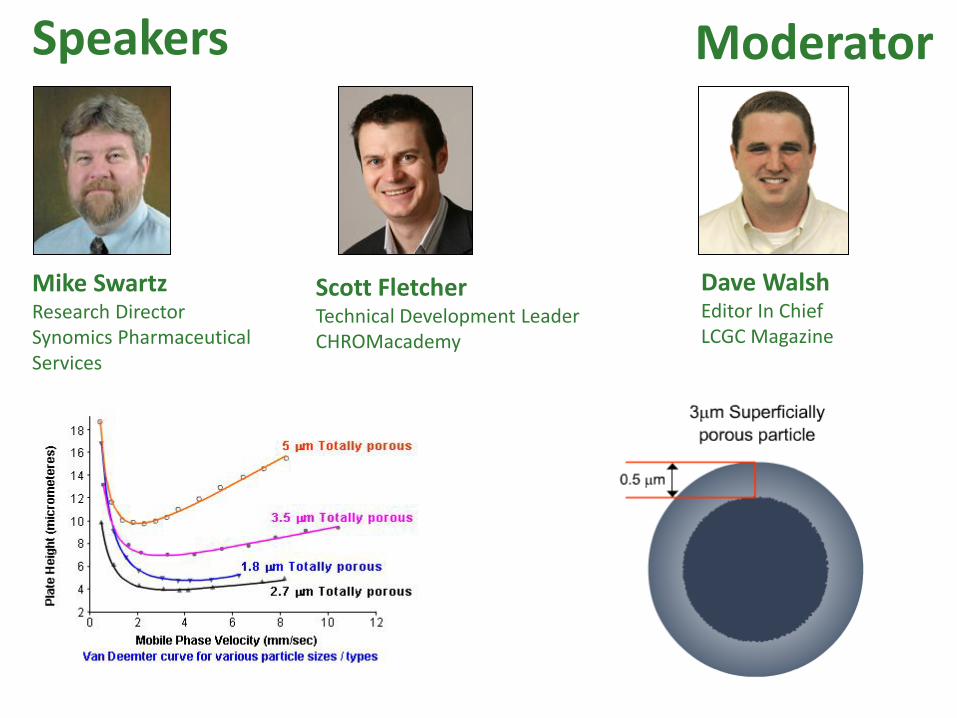
Speakers
Mike Swartz Research Director Synomics Pharmaceutical Services
Scott Fletcher Technical Development Leader CHROMacademy
Moderator
Dave Walsh Editor In Chief LCGC Magazine


Rapidly Becoming Confused! Sub 2µm and Superficially Porous Stationary HPLC Phases

1. Setting the Scene on High
Efficiency HPLC
2. High Efficiency and the Van
Deemter equation
3. Sub 2 m Silica Particles
4. Downsides and Instrument
Requirements
5. Superficially Porous Particles
as an alternative
6. Translating Methods from
traditional particles
Aims & Objectives
Courtesy of Agilent Technologies, Santa Clara, CA

1. So what exactly is high
efficiency HPLC?
2. Increase in the number of
theoretical plates (N) per
separation
3. N for 100 x 4.6mm x 5 m
column = 5000 to 8000
4. N for 100 x 4.6mm x 1.8 m
column = 100,000+
5. Can achieve:
o Sharper peaks
o Higher peak capacity
o Higher resolution
o Higher throughput
Setting the Scene – High Efficiency HPLC
2
2/1
2
54.516W
t
W
tN r
b
r
H = L / N

Van Deemter Equation (1)

Van Deemter Equation (2)

1. Analyte molecules move
through different paths
within the column
packing material
2. Larger differences in
path-length with larger
particles and larger
particle size distributions
3. Eddy diffusion can be
minimized by:
oWell packed columns
oReduced diameter
packing materials
oNarrow particle size
distribution packing
Van Deemter (A Term) - Eddy Diffusion

Movie 1
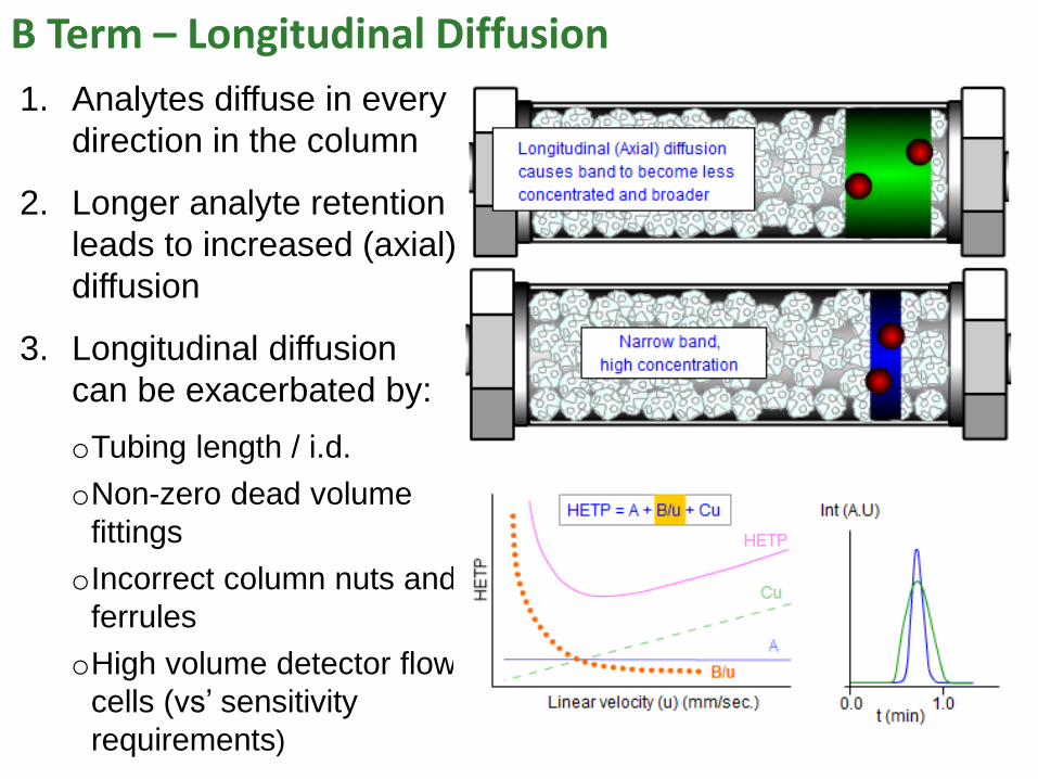
1. Analytes diffuse in every
direction in the column
2. Longer analyte retention
leads to increased (axial)
diffusion
3. Longitudinal diffusion
can be exacerbated by:
oTubing length / i.d.
oNon-zero dead volume
fittings
oIncorrect column nuts and
ferrules
oHigh volume detector flow
cells (vs’ sensitivity
requirements)
B Term – Longitudinal Diffusion

Movie 2

1. Diffusion into and out of
the pore structure is a
fixed rate process
2. This results in a ‘spread’
of elution times
3. Mass Transfer effects
can be minimized by:
oSmaller diameter
particles
oLow mobile phase flow
rates
oIncreasing column
temperature
Van Deemter (C Term) – Mass Transfer

Movie 3

Van Deemter (C Term) – Mass Transfer

Movie 4

1. Most people will be operating at the ‘practical optimum’ linear
velocity
2. In this region the shape and position of the curve is dictated
by the C-Term and the A-term
3. However, the effect from the B-Term must be negligible – see
latter section on instrumentation
Increasing Efficiency – How?

The two benefits associated with high efficiency separations are;
Increased Efficiency - Improved Resolution
1. Increasing Resolution
Driving toward a reduced Van Deemter Minimum.
The increased efficiency can be utilised to improve resolution
of complex mixtures. This is usually achieved by reducing the
diameter of the particles but maintaining column dimensions
Courtesy of Agilent Technologies, Santa Clara, CA

The two benefits associated with high efficiency separations are;
Increasing Efficiency – Faster Analysis
2. Increasing Sample Throughput / Reducing Analysis Time
In this case the composite van Deemter curve remains much
flatter post minimum – usually in conjunction with a reduction
in plate height. This is usually achieved by a reduction in
particle diameter, column dimensions and an increase in flow
and temperature
Courtesy of Agilent Technologies,
Santa Clara, CA

Increasing Throughput – Increasing Temperature
1. By increasing the separation temperature the C-Term is
reduced leading to a flatter post-minimum curve and faster
eluent linear velocity without compromising efficiency
2. This is due to the kinetic energy of the analytes being
increased as they diffuse in and out of the pores and the
viscosity of the ‘stagnant’ mobile phase in the pores is reduced
3. Care should be taken
to ensure that the
analyte does not
thermally degrade or
that peak co-elution or
inversion takes place

Increasing Efficiency – Reducing Particle Diameter
1. By reducing the particle diameter (size) we are reducing the
contributions from both the A-Term and the C-Term
2. Not only does this reduction lead to flatter curve post
minimum, it also leads to an overall reduction in plate height

1. The ‘price’ associated with employing reduced diameter
particles is an increase in operating back pressure
2. Even when increasing the separation temperature, the effect
of reducing particle diameter, especially if combined with a
reduction in column id and an increase in flow, is often
sufficient to necessitate the use of a high pressure UHPLC
instrument
Increasing Efficiency – Reducing Particle Diameter
3. Sub 2µm packed columns
use 0.5µm frits in order to
prevent loss of ‘fines’.
Frits of this size are very
prone to blocking unless
judicious sample preparation
is employed

UHPLC Instrumentation 1. We are experiencing an unheralded time when so many
manufacturers are launching new high pressure
instrumentation platforms

UHPLC Instrumentation
There are four key areas that differentiate UHPLC instruments
from standard HPLC instruments
1. Pump Adaptations
The traditional pressure limit for conventional HPLC
systems is 400bar (~6000psi)
UHPLC systems can operate at pressures exceeding
1000bar (14,500psi) and some UHPLC systems permit the
use of high flow rates at these pressures
In UHPLC pumps the pistons and pistons seals have
been redesigned to withstand the pressures, with some
systems incorporate silica carbide pistons in place of the
traditional synthetic sapphire

UHPLC Instrumentation
2. Gradient Dwell Reduction VD
The dwell volume is the total volume of the system from
where mobile phase mixing occurs to the analytical column
It usually exhibited as an isocratic hold at the start of a run
In order to achieve fast separations ‘ballistic’ gradients are
employed

UHPLC Instrumentation
3. Extra Column Volume ReductionVEC
“The total volume contributed by all system components and
capillary tubing from sample injection to detection, that are
not directly involved with the separation process”
The analyte band will diffuse in the mobile phase as it passes
through the system – van Deemter B-Term
Extra columns volume is the predominant factor in loss of
efficiency when using narrow internal diameter columns
Peak dispersion can be calculated by the Aris-Taylor equation;

UHPLC Instrumentation
3. Extra Column Volume ReductionVEC - Continued
From the previous equation we can conclude that the amount
the analyte band disperses is proportional to the length of
capillary tubing
However it is inversely proportional to the internal
diameter of the of the capillary tubing raised to the 4th power!

UHPLC Instrumentation
3. Extra Column Volume ReductionVEC - Continued
Many manufacturers employ
differently designed column end
fittings
It is essential to match the correct
ferrule type and depth with column
end fitting
Failure to do so can lead to a leak
from an unsecured connection or
an increase in extra column volume
resulting from a void

UHPLC Instrumentation 3. Improvements in Detector Speed
Data acquisitions rates are generally measured in
Hz – measurements per second
UHPLC peaks are much more efficient and narrow and
require faster acquisition speeds
Often mistaken for physical peak dispersion!
Courtesy of Agilent Technologies,
Santa Clara, CA

Increasing Efficiency: An alternative - SPS 1. Superficially Porous Silica particles (SPS)
were first developed over 40 years ago
2. They were used for the analysis of larger molecules
that conventionally generated inefficient, broad peaks
3. Consist of solid core or bead surrounded by a shallow
porous layer
Increasing Efficiency: An alternative - SPS
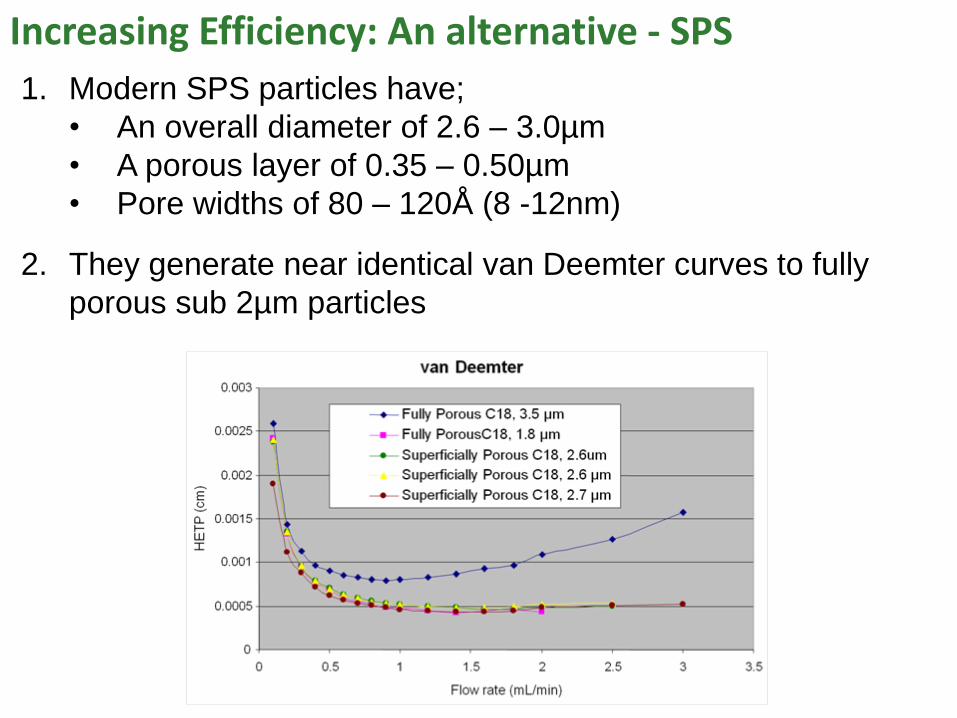
1. Modern SPS particles have;
• An overall diameter of 2.6 – 3.0µm
• A porous layer of 0.35 – 0.50µm
• Pore widths of 80 – 120Å (8 -12nm)
2. They generate near identical van Deemter curves to fully
porous sub 2µm particles

Increasing Efficiency: An alternative - SPS
1. Whilst they can achieve efficiencies
similar to 1.8µm fully porous particles,
they produce much lower operating
back pressures due to their larger
overall particle diameters
Sample (in peak elution order):
1. saccharin
2. caffeine
3. p-hydroxybenzoic acid
4. aspartame
5. dehydroacetic acid
6. benzoic acid
Courtesy of Agilent Technologies, Santa Clara, CA
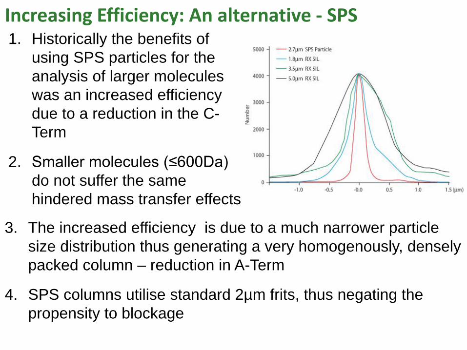
Increasing Efficiency: An alternative - SPS 1. Historically the benefits of
using SPS particles for the
analysis of larger molecules
was an increased efficiency
due to a reduction in the C-
Term
2. Smaller molecules (≤600Da)
do not suffer the same
hindered mass transfer effects
3. The increased efficiency is due to a much narrower particle
size distribution thus generating a very homogenously, densely
packed column – reduction in A-Term
4. SPS columns utilise standard 2µm frits, thus negating the
propensity to blockage

Converting HPLC methods to UHPLC Instruments
1. In order to successfully translate (geometrically scale) a
current HPLC method onto UHPLC instrument it is
important to follow some important rules
2. Flow rate (isocratic methods only), injection volume and
gradient times all need to be translated to ensure
satisfactory chromatography is achieved and enhanced
resolution and / or reduction in analysis time is realised
3. The resultant pressure can also be predicted
4. ‘Calculators’ available from most instrument / column
manufacturers and suppliers websites but good to have
knowledge of calculations used

Converting HPLC methods to UHPLC Instruments
1. We are going to translate the isocratic method as detailed
below on to a 50 x 2.1mm, 1.9µm UHPLC column
Conditions Column 1 Conditions Column 2
Column length (mm): 1L = 150
Column internal diameter (mm): 1CD = 4.6
Column particle size (μm): 1Pd = 5.0
Flow rate (mL/min): 1F = 1.0
Injection volume (μL): 1iV = 10
Pressure (bar): 1P
= 54
Gradient conditions Time %A %B
Initial Conditions 1gt = 0 95 5
Step 2 (initial hold) 1gt = 10 40 60
Step 3 1gt = 11 5 95
Column length (mm): 2L = 50
Column internal diameter (mm): 2CD = 2.1
Column particle size (μm): 2Pd = 1.9
Flow rate (mL/min): 2F = ?
Injection volume (μL): 2iV = ?
Pressure (bar): 2P
= ?
Gradient conditions Time %A %B
Initial Conditions 2gt = 0 95 5
Step 2 (initial hold) 2gt = ? 40 60
Step 3 2gt = ? 5 95

Converting HPLC methods to UHPLC Instruments
1. Flow rate conversion for Isocratic method
2
1
2
12
C
C
D
DFF
F2 - new flow rate, F1 - current flow rate,
DC2 - new column id, DC1 - current column id
2
26.4
1.2min/0.1
mm
mmmLF
F2 = 0.21mL / min

Converting HPLC methods to UHPLC Instruments
2. Injection Volume conversion
Vi2 = 0.7µL
1
2
2
1
212
L
L
D
DVV
C
Cii
mm
mm
mm
mmLVi
150
50
6.4
1.210
2
2
Vi2 - new injection volume, Vi1 - current injection volume,
DC2 - new column id, DC1 - current column id
L2 - new column length, L1 - current column length

Converting HPLC methods to UHPLC Instruments
3. Pressure conversion
P2 - new pressure, P1 is the current pressure,
dP1 particle diameter of current column, dP2 - new column,
DC2 new column id, DC1 - current column id
L2 - new column length, L1 - current column length
P2 = 126bar
11
22
2
22
1112
FL
FL
Dd
DdPP
CP
CP
min/0.1150
min/21.050
1.29.1
6.40.554
2
2mLmm
mLmm
mmm
mmmbarP

Converting HPLC methods to UHPLC Instruments
4. Converted Method
Conditions Column 1 Conditions Column 2
Column length (mm): 1L = 150
Column internal diameter (mm): 1CD = 4.6
Column particle size (μm): 1Pd = 5.0
Flow rate (mL/min): 1F = 1.0
Injection volume (μL): 1iV = 10
Pressure (bar): 1P
= 54
Gradient conditions Time %A %B
Initial Conditions 1gt = 0 95 5
Step 2 (initial hold) 1gt = 10 40 60
Step 3 1gt = 11 5 95
Column length (mm): 2L = 50
Column internal diameter (mm): 2CD = 2.1
Column particle size (μm): 2Pd = 1.9
Flow rate (mL/min): 2F = 0.21
Injection volume (μL): 2iV = 0.7
Pressure (bar): 2P
= 126
Gradient conditions Time %A %B
Initial Conditions 2gt = 0 95 5
Step 2 (initial hold) 2gt = ? 40 60
Step 3 2gt = ? 5 95

Converting HPLC methods to UHPLC Instruments
1. We are going to translate the gradient method as detailed
below on to a 50 x 2.1mm, 1.9µm UHPLC column
Conditions Column 1 Conditions Column 2
Column length (mm): 1L = 150
Column internal diameter (mm): 1CD = 4.6
Column particle size (μm): 1Pd = 5.0
Flow rate (mL/min): 1F = 1.0
Injection volume (μL): 1iV = 10
Pressure (bar): 1P
= 54
Gradient conditions Time %A %B
Initial Conditions 1gt = 0 95 5
Step 2 (initial hold) 1gt = 10 40 60
Step 3 1gt = 11 5 95
Column length (mm): 2L = 50
Column internal diameter (mm): 2CD = 2.1
Column particle size (μm): 2Pd = 1.9
Flow rate (mL/min): 2F = ?
Injection volume (μL): 2iV = ?
Pressure (bar): 2P
= ?
Gradient conditions Time %A %B
Initial Conditions 2gt = 0 95 5
Step 2 (initial hold) 2gt = ? 40 60
Step 3 2gt = ? 5 95
The flow rate remains the same as it is the change in mobile
phase composition (gradient) that dictates retention

Converting HPLC methods to UHPLC Instruments
1. Injection Volume conversion
Vi2 - new injection volume, Vi1 - current injection volume
DC2 - new column id, DC1 - current column id
L2 - new column length, L1 - current column length
Vi2 = 0.7µL
1
2
2
1
212
L
L
D
DVV
C
Cii
mm
mm
mm
mmLVi
150
50
6.4
1.210
2
2

Converting HPLC methods to UHPLC Instruments
2a. Gradient Segment Conversion
DC1 - column id, L1 - column length
W - column porosity (~68% or 0.68)
VM1 = 1695µL
or
VM1 = 1.7mL
VM1 – current column void volume
WLD
V C
M 1
2
1
12
68.01502
6.42
1 mmmm
VM

Converting HPLC methods to UHPLC Instruments
2b. Gradient Segment Conversion
DC2 - column id, L2 is column length
W - column porosity (~68% or 0.68)
VM2 = 117.8µL
or
VM1 = 0.12mL
VM2 – new column void volume
WLD
V CM 2
2
22
2
68.0502
1.22
2 mmmm
VM

Converting HPLC methods to UHPLC Instruments
2c. Gradient Segment Conversion
tG - gradient segment time, F is the flow rate,
S - shape selectivity value (5 in most cases),
ΔФ - mobile phase composition change, VM - column volume
Therefore
In order to maintain selectivity, the average retention factor, k*,
must be maintained
M
G
VS
Ftk *
2
2
1
11
22
2
11 M
G
M
G
VS
Ft
VS
Ft

Converting HPLC methods to UHPLC Instruments
2c. Gradient Segment Conversion
Therefore;
The flow, shape, selectivity and change in mobile phase
composition will remain the same.
2
2
1
1
M
G
M
G
V
t
V
t
1
212
x
M
MGG
V
Vtt

Converting HPLC methods to UHPLC Instruments
2c. Gradient Segment Conversion
Initial gradient segment translation.
1
212
x
M
MGG
V
Vtt
mL
mLtG
7.1
12.0min102
min71.02Gt

Converting HPLC methods to UHPLC Instruments
2d. Gradient Segment Conversion
Final gradient segment translation.
1
212
x
M
MGG
V
Vtt
mL
mLtG
7.1
12.0min112
min78.02Gt

Converting HPLC methods to UHPLC Instruments
3. Pressure conversion
P2 - new pressure, P1 - current pressure,
dP1- current particle diameter, dP2 - new particle diameter,
DC2 - new column id, DC1 - current column id
L2 - new column length, L1 - current column length
P2 = 600bar
11
22
2
22
1112
FL
FL
Dd
DdPP
CP
CP
min/0.1150
min/0.150
1.29.1
6.40.554
2
2mLmm
mLmm
mmm
mmmbarP

Converting HPLC methods to UHPLC Instruments
4. Converted Method
Conditions Column 1 Conditions Column 2
Column length (mm): 1L = 150
Column internal diameter (mm): 1CD = 4.6
Column particle size (μm): 1Pd = 5.0
Flow rate (mL/min): 1F = 1.0
Injection volume (μL): 1iV = 10
Pressure (bar): 1P
= 54
Gradient conditions Time %A %B
Initial Conditions 1gt = 0 95 5
Step 2 (initial hold) 1gt = 10 40 60
Step 3 1gt = 11 5 95
Column length (mm): 2L = 50
Column internal diameter (mm): 2CD = 2.1
Column particle size (μm): 2Pd = 1.9
Flow rate (mL/min): 2F = 1.0
Injection volume (μL): 2iV = 0.7
Pressure (bar): 2P
= 600
Gradient conditions Time %A %B
Initial Conditions 2gt = 0 95 5
Step 2 (initial hold) 2gt = 0.71 40 60
Step 3 2gt = 0.78 5 95
1. High efficiency HPLC has real benefits in terms of speed
and resolution
2. The Van Deemter equation and its band broadening
concepts help us to understand what the advantages are
3. Advances in silica particle technology help us realise these
benefits – Sub 2 m and Superficially Porous Materials
4. There are trade-offs in all approaches and instrument
requirements need to be considered
5. Translating methods from ‘traditional’ technologies needs
careful consideration
6. The benefits of high efficiency are available to everyone!
Summary

CHROMacademy & CHROMmunity
Today's Webcast was brought to you by CHROMacademy:
http://www.CHROMacademy.com
Join CHROMacademy for $295 per year includes all
CHROMacademy classes, labs, library and webcasts
All questions will be answered within CHROMmunity:
http://chrommunity.chromacademy.com
The webcast will be available for on-demand viewing
for 2 weeks from today


