www.polypipe.com42
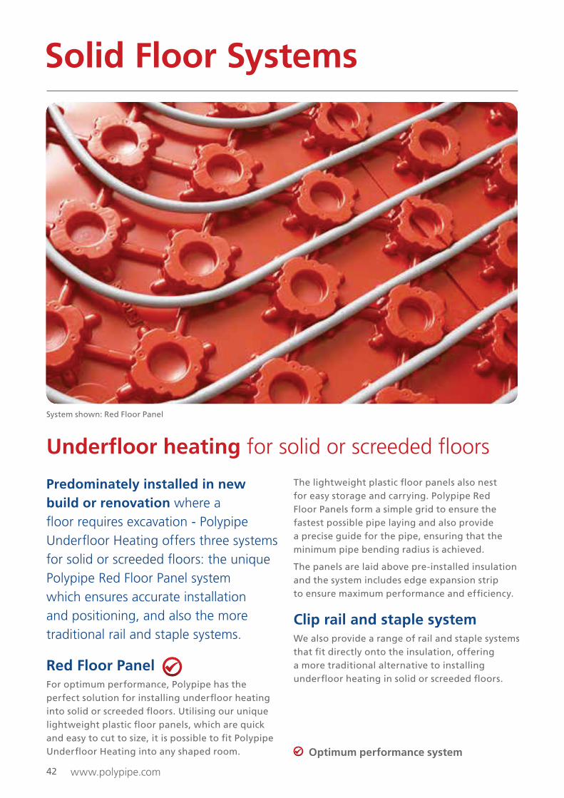
Under�oor heating for solid or screeded �oors
Predominately installed in new
build or renovation where a
�oor requires excavation - Polypipe
Under�oor Heating offers three systems
for solid or screeded �oors: the unique
Polypipe Red Floor Panel system
which ensures accurate installation
and positioning, and also the more
traditional rail and staple systems.
Red Floor PanelFor optimum performance, Polypipe has the
perfect solution for installing under!oor heating
into solid or screeded !oors. Utilising our unique
lightweight plastic !oor panels, which are quick
and easy to cut to size, it is possible to "t Polypipe
Under!oor Heating into any shaped room.
The lightweight plastic !oor panels also nest
for easy storage and carrying. Polypipe Red
Floor Panels form a simple grid to ensure the
fastest possible pipe laying and also provide
a precise guide for the pipe, ensuring that the
minimum pipe bending radius is achieved.
The panels are laid above pre-installed insulation
and the system includes edge expansion strip
to ensure maximum performance and ef"ciency.
Clip rail and staple systemWe also provide a range of rail and staple systems
that "t directly onto the insulation, offering
a more traditional alternative to installing
under!oor heating in solid or screeded !oors.
Solid Floor Systems
Optimum performance system
System shown: Red Floor Panel

www.polypipe.com 43
Solid Floor Systems
All systems
Solid !oor systems are compatible with our 15mm, 16mm and 18mm pipe ranges.
Polypipe Under!oor Heating Systems can be used with the following solid !oor constructions:
• Sand and cement screed (4:1 mix)
• Pumped screed systems (anhydrite etc.)
• Fine or heavy concrete
• Polymer modi"ed screeds
Design and materials
RED FLOOR PANEL CLIP RAIL STAPLE SYSTEM
KEY DESIGN INFORMATION
Typical heat output at 50°C
mean water temperature
91W/m2 at 100mm
pipe spacing
76W/m2 at 200mm
pipe spacing
76W/m2 at 200mm
pipe spacing
Recommended design
�ow temp.50°C 50°C 50°C
Maximum circuit length 100m 100m 100m
Maximum coverage
per circuit
11m2 at 100mm centres
22m2 at 200mm centres
30m2 at 300mm centres*
*(18mm pipe only)
22m2 at 200mm centres
30m2 at 300mm centres*
*(18mm pipe only)
11m2 at 100mm centres
22m2 at 200mm centres
MATERIAL REQUIREMENTS (APPROX)
Pipe
9m/m2 at 100mm centres
4.5m/m2 at 200mm centres
3.3m/m2 at 300mm centres*
*(18mm pipe only)
4.5m/m2 at 200mm centres
3.3m/m2 at 300mm centres
*(18mm Pipe only)
9m/m2 at 100mm centres
4.5m/m2 at 200mm centres
Floor panel usage1 panel/m2 allowing for
cutting (Actual 1.2m2/panel)N/A N/A
Clip rail usage N/A 1 x 1m rail/1m2 of !oor area N/A
Fixings N/A1 x bag (250 per 50m2
!oor area)N/A
Staple usage N/A N/A1 box (300) staples
for every 150m of pipe
Edge expansion strip 1.1m/m2 1.1m/m2 1.1m/m2
Conduit Pipe 2m/circuit 2m/circuit 2m/circuit
Product dimensions 1.2m x 1m (Height 30mm) 1m lengths 60mm/40mm
NOTE: Once a screed is poured, the red !oor panel will take up 15% of the volume of the screed.

www.polypipe.com44
Solid floor - All systems
Fitting insulation
Step 1:
In accordance with Part ‘L’ of the current Building
Regulations, a suitable layer of insulation material
should be included within the !oor construction.
It is the responsibility of the architect or builder
to ensure compliance. However, in all instances
insulation must be installed beneath the under!oor
heating system in order to ensure that any
downward heat loss does not exceed 10W/m2,
in accordance with BS EN 1264.
Fitting the edge expansion strips Step 2: Laying the insulation panels
When laying the insulation boards, ensure
that the joints of each board are staggered
and securely taped so as to minimise any risk
of movement.
Step 3: Fitting the edging strip
Using the edge expansion strip allows the free
expansion of the !oor screed. The expansion
strip comes with a self-adhesive strip which bonds
the panel to the wall, it should be installed
around the perimeter wall and around "xed
constructions such as columns, steps and access
doors. The edge expansion strip also comes with
a plastic skirt which lays over the top of the
insulation to prevent the screed seeping in to the
join between the insulation panel and edge
expansion strip. Edge expansion strip should be
"tted in addition to perimeter insulation
required by Building Regulations.
Solid Floor Systems - All Systems
Installation
Prior to installation it is recommended that the building is secured against the elements
and that the sub �oor is level, free from any mortar or plaster residues and is swept clean.
www.polypipe.com
Solid Floor Systems - Panels
45
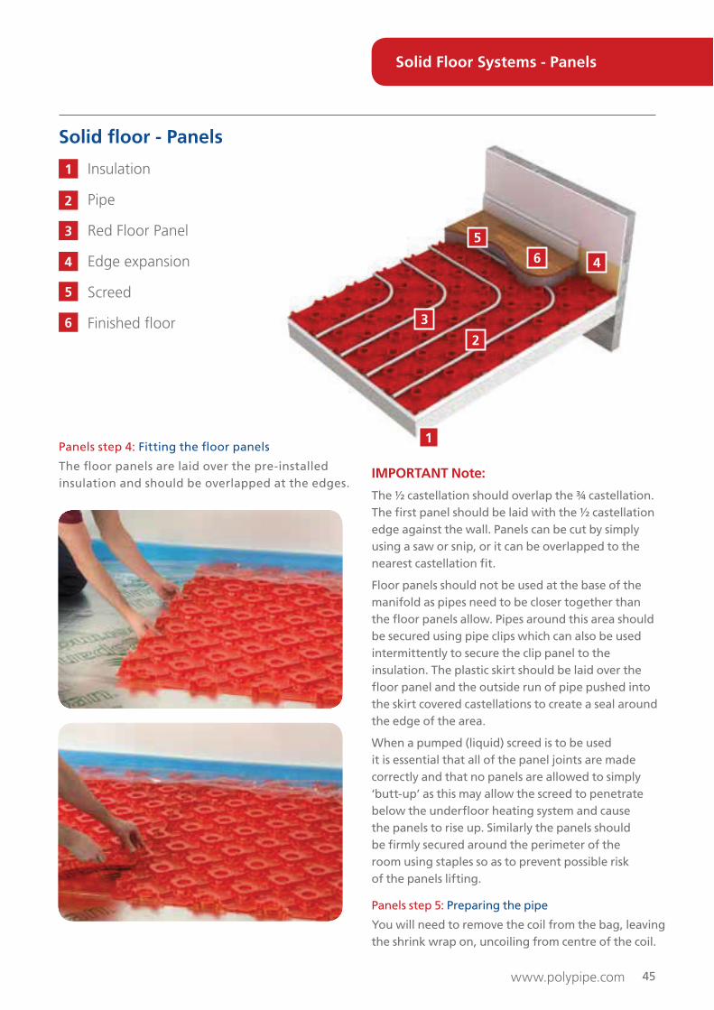
IMPORTANT Note:
The ½ castellation should overlap the ¾ castellation.
The "rst panel should be laid with the ½ castellation
edge against the wall. Panels can be cut by simply
using a saw or snip, or it can be overlapped to the
nearest castellation "t.
Floor panels should not be used at the base of the
manifold as pipes need to be closer together than
the !oor panels allow. Pipes around this area should
be secured using pipe clips which can also be used
intermittently to secure the clip panel to the
insulation. The plastic skirt should be laid over the
!oor panel and the outside run of pipe pushed into
the skirt covered castellations to create a seal around
the edge of the area.
When a pumped (liquid) screed is to be used
it is essential that all of the panel joints are made
correctly and that no panels are allowed to simply
‘butt-up’ as this may allow the screed to penetrate
below the under!oor heating system and cause
the panels to rise up. Similarly the panels should
be "rmly secured around the perimeter of the
room using staples so as to prevent possible risk
of the panels lifting.
Panels step 5: Preparing the pipe
You will need to remove the coil from the bag, leaving
the shrink wrap on, uncoiling from centre of the coil.
Solid floor - Panels
Insulation
Pipe
Red Floor Panel
Edge expansion
Screed
Finished �oor
Panels step 4: Fitting the !oor panels
The !oor panels are laid over the pre-installed
insulation and should be overlapped at the edges.
1
2
3
4
5
6
1
2
3
4
5
6

www.polypipe.com46
Panels step 6: Laying the pipe
Once you have completed laying the solid !oor
panels the pipe can be "tted starting at the
manifold position in line with the pre-designed
centres. 15mm and 18mm pipe can be laid at
100mm or 200mm centres as required, 18mm
pipe can also be laid at 300mm centres. The
minimum bend radius is achieved by encircling
two castellations for a 90° bend or three
castellations for a 180° bend.
Solid Floor Systems - Panels

www.polypipe.com 47
Panels step 7:
Circuits being laid at 100mm or 200mm centres
must be laid in a spiral con"guration. The "rst loop
of pipe should be laid around the perimeter of the
area to be covered by that circuit. The next loop
of this circuit should be laid either 200mm from
the "rst loop of pipe for 100mm centres or 400mm
from the "rst loop of pipe for 200mm centres.
Panels step 8:
Continue to loop the pipe into the centre of
the panels leaving enough space to form a double
return (‘S’ shape in the centre of the loop).
Panels step 9:
Now work back out from the centre by "lling the
space between the inwardly spiralling loop of the
primary circuit ensuring the pipe is laid at the
correct spacing centres.
18mm pipe installation formation
Where 300mm centre spacing is required (18mm
pipe systems only) a meander pattern can be used.
The pipe simply crosses the room from one side
to the other encapsulating 3 castellations at each
return bend.
Solid Floor Systems - Panels

www.polypipe.com
1
2
3
4
5 6
48
It is not necessary to overlap the clip rails.
They can be clipped together end to end to
form longer lengths.
Solid floor - Clip Rail system
Insulation
Pipe
Edge expansion
Clip rail
Screed
Finished �oor
Step 1 - Step 3:
Follow steps 1, 2 and 3 from page 44 of the Solid
Floor Systems section.
Rail step 4: Fitting the clip rails
Secure the clip rails to the insulation board by
using the clips (PB02911). Firmly push the clips
downwards into the insulation at 200mm centres
so as to ensure that the clip rail is fully secured
and lays !at to the insulation.
Continue to "t the clip rail across the room at 1m
intervals making sure that suf"cient space is left
around the perimeters of the room (approx.
800mm) so to accommodate any pipe returns or
connection lengths back to the manifold. Care
should also be taken to ensure that the clipping
alignment is maintained.
1
2
3
4
5
6
Solid Floor Systems - Clip Rail

www.polypipe.com
Solid Floor Systems - Clip Rail
49
Rail step 5: Laying the pipe
Fit the pipe into the clip rails at 200mm centres
in a serpentine pattern and then bend the pipe
at 180° at the end of each circuit ensuring that
the edge of the bend is parallel with the
adjacent circuit.
Continue to lay the pipe in this serpentine pattern
until you have reached the end of the circuit.
If necessary use an additional clip or pipe staple
(PB02930) to "rmly secure the 180° return bends.
Continue to "x the pipe down using the pipe
staples as you exit the pipe from the circuit.
The plastic skirt should be laid over the insulation
and the outside run of pipe stapled into the skirt
covered insulation to create a seal around the
edge of the area.

www.polypipe.com
1
2
3 6 4
5
50
The pipe should be installed at 200mm centres.
Solid floor - Staple system
Insulation
Pipe
Edge expansion
UFCH Staple Clip
Screed
Finished �oor
Step 1 - Step 3:
Follow steps 1, 2 and 3 from page 44
of the Solid Floor Systems section.
Staple step 4: Using the Staple Gun
Load the staples from the top and secure with the
plastic weight so to ensure the staples stay in position.
Staple step 5: Fitting the pipe
The pipe should be laid in the same spiral or
serpentine pattern as the panel system with the
staples "xed at a minimum of 500mm centres.
1
2
3
4
5
6
The plastic skirt should be laid over the
insulation and the outside run of pipe stapled
into the skirt covered insulation to create a seal
around the edge of the area.
Solid Floor Systems - Staple

www.polypipe.com 51
Expansion joint
BS EN 1264-4 recommends that an expansion
joint is constructed in stone and ceramic
"nished screeds for every 40m2 of !oor area
at a maximum length of 8m and an aspect ratio
of 2:1. An expansion joint is also required in
long narrow areas such as corridors etc.
The image (to the left) shows a typical arrangement
where the pipes pass through either an expansion
or a day joint. A strip of edge expansion is used to
provide the expansion capacity.
Step 9: Testing
BS EN 1264-4 recommends that an expansion
tightly compacted around the pipe to ensure that
no voids are present. The system should remain
under pressure (6 bar) in order to prevent the risk
of any damage being caused to the walls of the
pipe whilst the screed is being applied.
Step 10: Laying the screed
The overall quality and thickness of a sand and
cement screed should meet the requirements
of BS8204-1 which stipulates that in domestic
or light commercial applications a minimum
thickness of 65mm should be used. The thickness
of alternative coverings, such as anhydrite or
polymer modi"ed screeds, may differ depending
on construction requirements. This information
should therefore be provided by the specialist
screed manufacturer/supplier.
Under no circumstances should the under!oor
heating system be used to arti"cially dry/cure the
screed as this could cause the screed to crack and
seriously undermine the integrity of the !oor
construction. Once the screed has fully cured,
the under!oor heating system can be switched
on and the manifold !ow temperature slowly
increased up to the calculated design temperature.
For further information regarding !oor screeding
requirements for under!oor heating systems
please refer to BS8204-1 or the BISRIA Guide:
Screeds with Under!oor Heating.
All solid floor systems
Conduit Pipe
A 400mm length of conduit pipe should be "tted
over the under!oor heating pipe in any situation
where damage may be caused to the pipe
i.e. where the pipe passes through internal walls
or doorways, where the pipe emerges through
the !oor up to the manifold or where the pipe
passes through either an expansion or day joint.
Preformed long radius bends can also be used
to provide a neater solution if required.
A section of conduit pipe 400mm long should
be "tted around the heating pipe where the
pipe passes through the edge expansion strip,
e.g. room to room, or through expansion joints
within the !oor.
Conduit pipe should also be used where the
pipe leaves the !oor adjacent to the manifold.
This can be threaded down the pipe after the
pipework has been installed.
Conduit
Pipe
Insulation
Sub !oor
Solid Floor Systems - Staple

www.polypipe.com52
Finishing
Timber �oors
The use of timber !ooring is perfectly acceptable
with our solid !oor under!oor heating systems.
However, care must be taken to ensure that the
product being used is suitable for use with
under!oor heating (please consult your specialist
!ooring supplier). It is essential that the new
screed !oor is allowed to dry out completely
before the timber !ooring product is laid. It is
recommended that the under!oor heating system
be run for at least two weeks to completely dry
out the sub!oor prior to the laying of the timber
!ooring product.
If you are using a natural timber !ooring product
then it should be allowed to acclimatise
suf"ciently prior to installation. The timber !oor
can be either ‘!oated’ or ‘glued’ to the screed
!oor depending on the product type and
installation preference.
When designing the system, care must be taken
to ensure that !oor surface temperature (on top
of the timber "nish !oor) does not exceed 27°C.
Application of timber floors over solid
floor systems
Where solid oak !ooring is to be laid on a solid
!oor, joists can be "tted at 1m centres to provide
a "xing point for the boards. Insulation, solid
!oor panels and pipe can be laid between the
joists and screed laid level with the top of the
joists (see diagram above). Individual circuits
of pipe are then laid between each set of joists
with care being taken to ensure the screed is
completely dry prior to "tting the solid oak
covering (see diagram below).
Timber �oor covering
Screed
Pipe
Solid Red Floor Panel
Joists at 1m spacings
1
2
3
4
5
Solid Floor Systems - All Systems
1
2
3
4
5

www.polypipe.com 5353www.polypipe.com


