
www.tacmina.com
Solenoid-drivenDiaphragm Metering Pump
EC-054 (5) 052014/7/ASSHead Office:
2-2-14 Awajimachi, Chuo-ku, Osaka 541-0047 JapanTel.+81(0)6-6208-3974 Fax.+81(0)6-6208-3978URL http://www.tacmina.comE-mail [email protected]
Product designs and specifications are subject to change without notice for product improvement.
■ Related equipments
25 to 1000LTank capacity
Relief valve automatically releases excessive pressure that builds up inside the discharge side pipes due to clogging of the pipes or while the discharge valve is closed. It can prevent accidents such as damage to the pump or piping.
● Relief valve (safety valve)
● Flow checkerFlow checker is highly resistant to acid and alkalis and allows the injection operation of the pump to be checked at low cost. The pump-direct connection type and hose connection type are the two types of volume checkers available.
Degassing joint is installed at the suction side of a pump. It separates absorbed air bubbles from the liquid to prevent air bubbles from entering the pump head.
This joint is supplied with the DCLPW series as standard equipment.
*
● Degassing joint
Back pressure valve prevents excessive liquid flow and siphon effect by sealing the outlet port of the liquid with a diaphragm, and by applying just enough force (back pressure) to overcome the fluid inertia force.
● Parts kitParts kit includes all required consumables in a set and is more economical than purchasing the parts separately. Since all consumables are packaged in one box, it also makes inventory management easier.
● Back pressure valve
These optional products enable you to check the injection operation visually as well as by means of a sensor.
● Flow indicator and photoelectric sensorFloat switch will stop the pump when the remaining volume of chemical liquid in the tank becomes low. They also cause an alarm to be emitted to notify you that it is time to refill the liquid. Two types of float switches are available, namely the float type with choices of one-point and two-point type sensors, and the electrode type, which is highly resistant to chemicals.
● Float switch
Solution tank PE tank PVC tank
Tank
■ Options
● Residual pressure exhaustion valveResidual pressure exhaustion valve is directly connected to the discharge side of the pump so that the pipes can be safely purged of abnormal pressure that builds up. It also enables residual pressure and residual liquid to be safely discharged when maintenance services are performed.
● Pulse generator type flowmeterWhen using this flowmeter in combination with a Tacmina pulse signal input type metering pump, you can construct a simple and low-cost injection system proportional to the required flow rate.
PTSChemical injection system
30/50/120 LTank capacity
Pump and tank combination
●Compact design and easy to assemble in equipment and install.●You can start operation by simply connecting the power supply and piping.
TM_00146571_H01_H04_1407_1_1C M Y K
CLPWCLPWM
CLPWT
CLPZ
DCLPWDCLPWM
DCLPWT
Digital-input/outputDigital-input/output &Analog-inputDigital-input/output &Timer Control
Digital-input/outputDigital-input/output &Analog-inputDigital-input/output &Timer ControlDigital-input/outputDigital-input/output &Analog-inputDigital-input/output &Timer ControlNo-Input
PWPWM
PWT
PW
DCLPWAir Block
In-Line Automatic Air-release
In-Line Automatic Air-releaseCLPW
CLPZ
1 2
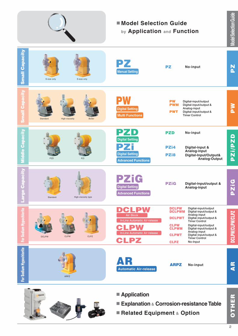
■ Application
■ Explanation & Corrosion-resistance Table
■ Related Equipment & Option
PZi8
PZi4 Digital-input &Analog-inputDigital-Input/Output& Analog-Output
PZ No-input
PZD No-input
No-inputARPZ
PZiG Digital-input/output &Analog-input
Model Selection Guideby Application and Function
PZDDigital Setting
PZiDigital Setting
PZiGDigital Setting
Advanced Functions
Digital Setting
Multi Functions
Advanced Functions
ARAutomatic Air-release
PZManual Setting
Standard High-viscosity type
PZIPZD
S-size only S-size only
Mode
l Sele
ction
Guide
PW
PZ
PZ
i/P
ZD
DCLP
W/CL
PW/CL
PZA
RO
TH
ER
PZ
iG
CLPW CLPZDCLPW
Standard High-viscosity Boiler
ARPZ
Sm
all C
apacit
yS
mall
Cap
acit
yM
iddl
e C
apac
ity
Larg
e C
apacit
yFo
r Sod
ium H
ypoc
hlorit
eFo
r Sod
ium H
ypoc
hlorit
e
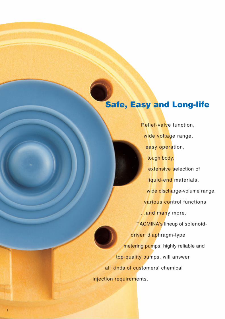
Relief-valve function,
wide voltage range,
easy operation,
tough body,
extensive selection of
liquid-end materials,
wide discharge-volume range,
various control functions
...and many more.
TACMINA's lineup of solenoid-
driven diaphragm-type
metering pumps, highly reliable and
top-quality pumps, will answer
all kinds of customers' chemical
injection requirements.
Safe, Easy and Long-life
TM_00146571_P01_P02_1407_1_1C M Y K
CLPWCLPWM
CLPWT
CLPZ
DCLPWDCLPWM
DCLPWT
Digital-input/outputDigital-input/output &Analog-inputDigital-input/output &Timer Control
Digital-input/outputDigital-input/output &Analog-inputDigital-input/output &Timer ControlDigital-input/outputDigital-input/output &Analog-inputDigital-input/output &Timer ControlNo-Input
PWPWM
PWT
PW
DCLPWAir Block
In-Line Automatic Air-release
In-Line Automatic Air-releaseCLPW
CLPZ
1 2
■ Application
■ Explanation & Corrosion-resistance Table
■ Related Equipment & Option
PZi8
PZi4 Digital-input &Analog-inputDigital-Input/Output& Analog-Output
PZ No-input
PZD No-input
No-inputARPZ
PZiG Digital-input/output &Analog-input
Model Selection Guideby Application and Function
PZDDigital Setting
PZiDigital Setting
PZiGDigital Setting
Advanced Functions
Digital Setting
Multi Functions
Advanced Functions
ARAutomatic Air-release
PZManual Setting
Standard High-viscosity type
PZIPZD
S-size only S-size only
Mode
l Sele
ction
Guide
PW
PZ
PZ
i/P
ZD
DCLP
W/CL
PW/CL
PZA
RO
TH
ER
PZ
iGCLPW CLPZDCLPW
Standard High-viscosity Boiler
ARPZ
Sm
all C
apacit
yS
mall
Cap
acit
yM
iddl
e C
apac
ity
Larg
e C
apacit
yFo
r Sod
ium H
ypoc
hlorit
eFo
r Sod
ium H
ypoc
hlorit
e
Relief-valve function,
wide voltage range,
easy operation,
tough body,
extensive selection of
liquid-end materials,
wide discharge-volume range,
various control functions
...and many more.
TACMINA's lineup of solenoid-
driven diaphragm-type
metering pumps, highly reliable and
top-quality pumps, will answer
all kinds of customers' chemical
injection requirements.
Safe, Easy and Long-life
TM_00146571_P01_P02_1407_1_1C M Y K

Mode
l Sele
ction
Guide
100R60R30R 100R60R30R
~50~50 ~50 ~50 ~50
○ ○
PVC/PVDF/SUS PVC/PVDF/SUS PVC/PVDFPVC
DCLPW
Easy calibration functionMomentary discharge-volume display function*2
PZD PZi4 PZi8 PZiG DCLPWCLPW
DCLPWMCLPWM
DCLPWTCLPWT CLPZ ARPZPWPZ PWM PWT
○
6030
1.0
100
0.70.7
Stroke speedDischarge volumePercentagePulse-input proportional controlAnalog-input proportional controlInterval operationTimer controlCount operation(batch control)
External operation-signal control
External stop-signal control2-point Level Switch control*1
ECO modeSAFE modeRelief valve functionAlarm function
1
2
1
○
○○○○○○○○
○
○
2
○
○
—
—
—
—
—
————————————————————
——
—
—
—
—
—
————————————————————
——
—
—
—
—
——————————
——
—
—
—
—
—
2
○
○
○
4
2
○
○
○
○
○
○
○
4
2
1○○○○○○○○○○○○○
○
○
○
1
○○○○○○○○○
○○
2
○○○○
1
2
1○
○
○○○○○○○
○
○
2
○
○
○
2
○○○○
———
CLPWCLPWM
CLPWT
~50
○ ○
6030
1.0
100
0.70.7
Middle Capacity Large Capacity
PZDPZi8PZi4
PZiDigital Setting
Digital Setting
AdvancedFunctions
PZiGPZiG
Digital Setting
Advanced Functions
Digital-input/outputDigital-input/output &Analog-inputDigital-input/output &Timer Control
PWPWM
PWT
Digital-input/outputDigital-input/output &Analog-inputDigital-input/output &Timer Control
PWPWM
PWT
Digital-input/outputDigital-input/output &Analog-inputDigital-input/output &Timer Control
PWPWM
PWT
PZDNo-inputNo-input PZi8
PZi4Digital-input &Analog-input
Digital-input/output &Analog-input
PZiGDigital-input/output &Analog-input
No-inputNo-input Digital-input/output &Analog-input
By Application
For Injection of General Chemicals
For Injection of Boiler / High-pressure For Injection of High-viscosity Chemicals
30 60100R60R30R 100
0.7 1.0 0.4
w/ Relief Valvew/ Relief Valvew/ Relief Valve
0.4 0.8
126131
1.0 0.40.810.0 7.07.0 10.0 7.07.0 7.0 10.0 4.04.0 8.0 10.0 4.08.0
CLPZ ARPZAutomaticAir-release
CLPWCLPWMCLPWT
In-LineAutomaticAir-release
CLPW
DCLPWDCLPWM
DCLPWT
Digital-input/outputDigital-input/output &Analog-inputDigital-input/output &Timer Control
Digital-input/outputDigital-input/output &Analog-inputDigital-input/output &Timer Control
No-input
Acrylic (PMMA)
By Function For details on each product, see the reference page forthe respective model or "Explanation" on page 26.
Series
Analog Input
Digital
Input
OutputSignal
(No. of ports)
Control
Power supply to Flow Checker
Manual
Auto
Function
w/1-point Level Switchw/2-point Level Switch
Memory-read error (LCD display only)
Pulse-Input error
Analog-Input error
Lower discharge-volume alarm*2
Tank-levelalarm
Error/Alarm
—
—
——
○○○
○
○
30R
301.8
60R
603.6
100R
1006.00.44.0
30
301.81.010.0
60
603.60.88.0
100
1006.00.44.0
300
36021.60.33.0
500
54032.40.22.0
300
34020.41.010.0
500
53031.80.77.0
700
76045.60.44.0
1000
100060.00.33.0
300
36021.60.33.0
500
54032.40.22.0
200
22013.20.22.0
30R
301.8
60R
603.60.7
100R
1006.0
30
301.8
60
603.6
100
1006.00.70.7
7.01.010.0 7.07.0
~50~50 ~3000*1
○○
PVCPVC
Middle Capacity Large Capacity
PZiGPZiG
Digital Setting
Advanced Functions
30R 30R 3030 30
251.52.020.0
60
603.61.010.0
100
1006.00.77.0
300
36021.60.33.0
500
54032.40.22.0
300
34020.41.010.0
500
53031.80.77.0
700
76045.60.44.0
1000
100060.00.33.0
1 When transferring high-viscosity liquids, the maximum discharge volume may be lower than the specified volume depending on the characteristics of the liquid and operating conditions. Consult TACMINA separately when transferring high-viscosity liquids.* 1 When 2-point Level Switch is used*2 When Flow Checker is used*
6030 906030 90 6030 906030 90 60306030 100 100 9354273.61.8 5.43.61.8 5.4 3.61.8 5.43.61.8 5.4 3.61.83.61.8 6.0 6.0 5.583.241.62
(display only)
(display only)
(display only)
w/ Relief Valve
w/ Relief Valve w/ Relief Valve
w/ Relief Valve
281.681.515.0
281.681.515.0
○
○
43
Model
Series Series
Signal
mL/min
MPaL/h
bar
L/h
bar
L/h
bar
Max. dischargevolume
Max. allowable viscosity
Relief valve function
Max. dischargepressure
mPa.s
Reference page
Liquid-end material
Model
Signal
mL/min
MPa
Max. dischargevolume
Max. allowable viscosity
Relief valve function
Max. dischargepressure
mPa.s
Reference page
Liquid-end material
PWPWMPWT
PWDigital Setting
Multi Functions
Small CapacitySmall Capacity
GO toP7
GO toP13
GO toP17
GO toP21
GO toP23
DCLPWDCLPWMDCLPWT
Air Block
In-Line AutomaticAir-release
For Injection of Sodium Hypochlorite
Middle Capacity For Sodium HypochloriteLarge CapacitySmall Capacity
PZManual Setting
Model
Series
Signal
mL/min
MPa
Max. dischargevolume
Max. allowable viscosity
Relief valve function
Max. dischargepressure
mPa.s
Reference page
Liquid-end material
PWPWMPWT
PWDigital Setting
Multi Functions
PWPWMPWT
PWDigital Setting
Multi Functions
Small Capacity Small CapacitySmall Capacity
GO toP7
GO toP5
GO toP5
GO toP7
GO toP13
GO toP17
PZManual Setting
PZDDigital Setting PZD
TM_00146571_P03_P04_1407_1_1C M Y K

(30/60/100)(30R/60R/100R)
w/ Relief Valve
AC100 240V( 10%)Wide VoltageRange Power Supply
There is no need to worry about sitepower supply voltage or voltage fluctuationssince it can be used with AC100 to 240 V( 10%) power supplies. You can also keep it instock safely since it can be used for a variety of sites and applications.
Adjusting Dial forEasy Operation
Manual adjustment from15 to 300 pulses per minute
Simple StructureMinimum number of parts allows easy maintenance.
Solenoid
Pump shaftDischarge joint
Pump head
Diaphragm
Suction joint
Stroke-speed adjustment dial
OutdoorUse
OutdoorUse
Water- & Dust-proofSpecifications
IEC standard: IP65 or equivalent Avoid condensation and immersion in water.
Extensive Range of Liquid-end MaterialsFor details, refer to the "Liquid-end Material" table on the following page.
VTCET(for injection of boiler chemicals)Material: PVCApplication example:Transfer/ inject ion ofboiler chemicals
w/ Relief Valve
FTCE/FTCF/FTCTMaterial: PVDFApplication example:Transfer/ inject ion ofspecial chemicals(e.g. strong and mixed acids)
w/ Relief Valve
6TCTMaterial: Stainless steel(SUS316)Application example:Transfer/ inject ion ofsolutions/special chemicals
VTCE/VTCFMaterial: PVCApplication example:Transfer/ inject ion ofgeneral chemicals
w/ Relief Valve
Sm
all
Ca
pa
cit
y 60R/6030R/30 100R/100
FTCTVTCE VTCF FTCE FTCF FTCT 6TCTVTCE VTCF FTCE FTCF FTCT 6TCTVTCE VTCF FTCE FTCF
4 x 6(nylon tube)
4 x 9(PVC braided hose)
6 x 11(PVC braided hose)
6 x 8(PE)
1/4" x 3/8"(PE)
Specif ication
Model
( )VTCET
for injection ofboiler chemicals
mL/minL/hMPabar
Stroke speed
Stroke length
Max. allowable viscosity
Allowable temperature
Ambient humidity
Environmental protection
Altitude of instrallation location
Noise level
Max. discharge volume*1
Max. discharge pressure*1
301.8
0.7[1.0]7.0[10]
603.6
0.7[0.8]7.0[8.0]
281.681.5
15.0
1006.0
0.44.0
553.30.55.0
6TCT
271.60.55.0
955.7
Connection(hose/tube:I.D x O.D)
Discharge side
Suction side
Relief /air-release
Specification: PZ
4 x 9(PVC braided hose)
6 x 8(PE)
1/4" x 3/8"(PE)
6 x 8(PE)
1/4" x 3/8"(PE)
6 x 8(FEP)
1/4" x 3/8"(FEP)
6 x 8(PE)
1/4" x 3/8"(PE)
6 x 8(FEP)
1/4" x 3/8"(FEP)
6 x 11(PVC braided hose)
6 x 8(PE)
1/4" x 3/8"(PE)
6 x 8(PE)
1/4" x 3/8"(PE)
6 x 8(FEP)
1/4" x 3/8"(FEP)
6 x 8(PTFE)
6 x 8(PTFE)
6 x 8(PTFE)
15 to 300 strokes/min (dial setting)
Fixed at 1.0 mm
ManualOperationmode
AC 100 to 240 V ( 10%)1-phase/50 or 60 Hz
2.0 AMax.: 200 VA/Ave.: 15 W
1.7 kg
Rated voltageNo. of phases/FrequencyMaximum currentPower consumption
Powersupply
Weight
4 x 6 (soft PVC hose)
50 mPa.s
Ambient temperature: 0 to 40 /Transferring liquid: 0 to 40 (no freezing allowed)
35 to 85% RH
IEC standard: IP65 or equivalent (water- and dust-proof)
Less than 1,000 m
Less than 85 dB
Setting stroke speed (15 to 300 strokes/min) w/ manual dial
65
No-input
PZ
1 4 5 632
Model Code Not all model combinations are possible. When selecting the pump model, f irst check "Specif ication" and "Liquid-end Material".
PZ 30R VTCE 4x9PVC W S JPL
[for injection of general chemicals]Model (discharge volume standard)1 Joint specification4 Applicable standard5 Power plug6Hose standard (size/material)3Liquid-end material2
30R : 30 mL/min (w/ Relief Valve)
60R : 60 mL/min (w/ Relief Valve)
100R : 100 mL/min (w/ Relief Valve)
30 : 30 mL/min60 : 60 mL/min
100 : 100 mL/min
30R : 30 mL/min (w/ Relief Valve)
30 : 30 mL/min
VTCEVTCFFTCEFTCFFTCT6TCT
VTCET
4 x 9 PVC6 x 11 PVC6 x 8 PE/FEP/PTFE
1/4" x 3/8" PE/FEP
4 x 6 PA
W : Standard
BW : Boiler
S : StandardCE : CE marking-compatible
EUP : Euro plugULP : UL plugAUP : Australia plugUKP : UK plugJPL : Japan lead wire
[for injection of boiler chemicals]
( )VTCET
for injection ofboiler chemicalsPart
Model
Also refer to the "Corrosion-resistance Table" on page 26.Liquid-end Material
Pump head
Diaphragm
Check ball
O-ring
Valve seat
Joint
Ball stopper
PVC
PVC
PVC
EPDM
EPDM
Fluoro-rubber
Special fluoro-rubber
EPDM
EPDM
PVDF PTFE (valve stopper)
PVDF
PTFE
Ceramic
Fluoro-rubber
Special fluoro-rubber
PVDF
PVC
EPDM
PTFE
PVC
PVC
Special fluoro-rubber
PTFE
SUS316
PTFE
SUS316
PTFE (valve stopper)
VTCE VTCF FTCE FTCF FTCT 6TCT
Pafulo
( )VTCET
for injection ofboiler chemicals
Power cable (2 m) is attached.Accessory
3 m
*1 For details on the hose/tube aperture, see "Connection" for the respective model in "Specification" table above.
*2 This hose is already attached to 30R/60R/100R models.
1 m*2 1 m*2
FTCT 6TCTVTCE VTCF FTCE FTCF
2 sets (M5 x 30)
1 set
1 set
1 piece1 piece
1 set
1 set*2 1 set
30R/60R/100R30/60/100
Hose/ Tube*1
Relief /air-release hose*1
Anti-siphon check valve
Foot valve
Ceramic weight
Hose pump for air-release
INSULOK for Relief /air-release hose
Pump mounting nuts / bolts
Operation manual
Discharge side : 2 m
Suction side : 1 m
Item
Model
1 set(R1/2)
1 set(R1/2)
1 set(R1/2 or R3/8)
The shape and dimensions differ slightly depending on the liquid-endmaterial and connection type.The mounting pitch allows mounting from 87 to 110 mm.
87
R3 6
( A)
118
130
110(F)
BD
C
E G
External Dimension (mm)
VTCE/VTCFFTCE/FTCF/FTCTVTCET
(A) B C D E G(F)
206227.5193
152195139
7697.576
7069.570
7697.563
16.517.516.5
150.5142
150.5
Model
Manual Setting
PZ
TM_00146571_P05_P06_1407_1_1C M Y K

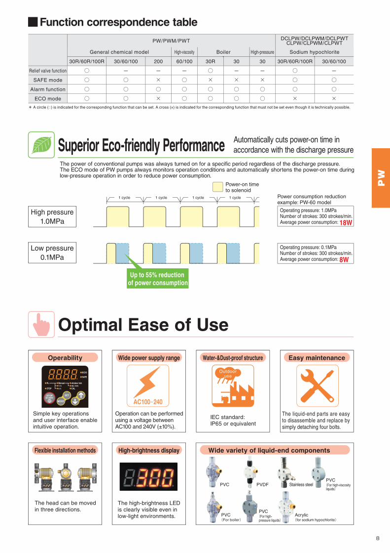
Optimal Ease of Use
■Function correspondence table
Superior Eco-friendly Performance
Relief valve function
SAFE mode
Alarm function
ECO mode
30R/60R/100R
○
○
○
○
30/60/100
-
○
○
○
30R/60R/100R
○
○
○
×
30/60/100
-
○
○
×
200
-
×
○
×
60/100
-
○
○
○
30R
○
×
○
○
30
-
×
○
○
30
-
×
○
○
General chemical model Sodium hypochlorite
DCLPW/DCLPWM/DCLPWTCLPW/CLPWM/CLPWTPW/PWM/PWT
High-viscosity Boiler High-pressure
Automatically cuts power-on time in accordance with the discharge pressure
Wide power supply range
Operation can be performed using a voltage between AC100 and 240V (±10%).
Simple key operations and user interface enable intuitive operation.
Outdooruse
IEC standard: IP65 or equivalent
Water-&Dust-proof structure Easy maintenanceOperability
High-brightness display Wide variety of liquid-end componentsFlexible installation methods
The head can be moved in three directions.
High pressure1.0MPa
Low pressure0.1MPa
1 cycle 1サイクル1 cycle1 cycle1 cycle
Up to 55% reduction of power consumption
The liquid-end parts are easy to disassemble and replace by simply detaching four bolts.
* A circle (○) is indicated for the corresponding function that can be set. A cross (×) is indicated for the corresponding function that must not be set even though it is technically possible.
Power-on time to solenoid
Power consumption reduction example: PW-60 model
Operating pressure: 1.0MPaNumber of strokes: 300 strokes/min.Average power consumption: 18W
Operating pressure: 0.1MPaNumber of strokes: 300 strokes/min.Average power consumption: 8W
ECO
SAFE
PL
STOP
Manual1/n×n
strokes/minmL/minCAL
ECO
SAFE
PL
STOP
Manual1/n×n
strokes/minmL/minCAL
ECO
SAFE
PL
STOP
Manual1/n×n
strokes/minmL/minCAL
The high-brightness LED is clearly visible even in low-light environments.
Stainless steelPVDF
Acrylic(for sodium hypochlorite)
PVC(For boiler)
PVC(For high-pressure liquids)
PVC(For high-viscosity liquids)
PVC
The power of conventional pumps was always turned on for a specific period regardless of the discharge pressure.The ECO mode of PW pumps always monitors operation conditions and automatically shortens the power-on time during low-pressure operation in order to reduce power consumption.
■Safety function selection flow
Higher Safety Three types of safety functions that realize higher rank risk management
While the discharge valve is closed, the liquid transfer force is controlled to prevent pressure buildup.
When the pressure exceeds the setting value, the relief valve operates automatically.
When abnormal pressure builds up due to clogging of the pipes or while the discharge valve is closed, an alarm is emitted to warn this condition.
*Standard type pump discharge pressure: 0.7MPa. Boiler-type pump discharge pressure: 1.5MPa.*The Relief valve function cannot be selected for
SUS type, high-viscosity type, and high-pressure type pumps.
*When the alarm function is used together with the SAFE mode, an alarm is emitted for pressure lower than the normal pressure.*This funct ion is disabled at the factory default
setting.
*To use the SAFE mode, set the stroke length to 100%.*The SAFE mode is not available for PW-200, boiler
type and high-pressure type.*The funct ion is disabled at the factory default
setting.
SAFE mode for preventing abnormal pressure buildup
Relief valve function for releasing abnormal pressure
Alarm function for notifying abnormal pressure
Prevents abnormal pressure buildup
Requires a discharge pressure of 0.7MPa minimumOutputs an alarm when abnormal pressure builds up
SAFE modeSAFE mode
Alarm functionAlarm functionRelief valve function
Automatically releases pressure
Alarm output
STOP!
PW
87
Digital-input/outputDigital-input/output &Analog-inputDigital-input/output &Timer Control
PWPWM
PWT
PWDigital Setting
Multi Functions
Sm
all
Ca
pa
cit
y
TM_00146571_P07_P08_1407_1_1C M Y K
No.1 Mon
Tue
Wed
Thu
Fri
Sat
Sun
ON time
OFF time
ON time
OFF time
ON time
OFF time
ON time
OFF time
ON time
OFF time
ON time
OFF time
ON time
OFF time
No.2
No.3
No.4
No.5
No.6
No.7
Mon0:00 12:00 12:00 12:00 12:00 12:00 12:00 12:00 12:00
Mon0:00
Tue0:00
Tue0:00
Wed0:00
Thu0:00
Fri0:00
Sat0:00
Sun0:00
24:00
9:00
30:00
36:00
‐‐:‐‐
36:00
32:00
18:009:00
12:00
9:00
‐‐:‐‐
12:00
0:00
Pump operation time
Time that can be set for each program
PWTTimer control
Item
Input signal
Output signal
Control
Digital
AnalogNumber of ports
Type
Digital
Number of strokes
Discharge volume control
Manual operation
Pulse proportional control
Analog proportional control
Timer control
External operation & stop input signal
Number of ports
Type
Setting example: ON period: 5 minutesOFF period: 3 minutes
The following combination of functions can also be used besides the abovementioned combination.
■Setting example
Setting example: ON time:OFF time:
The pump automatically operates every week at the same ON and OFF time being set for the day of the week.You can set one program pattern for each day of the week. You can set the ON time from 0:00 to 24:00 and OFF time within the range 0:00 to 48:00 in 1-minute unit.*WEEK mode cannot be used together with DAY mode.
Pump operation can be turned on and off in accordance with the setting of the timer. You can set any ON and OFF period for one pattern each in the range of 1 to 9999 minutes.
The pump operates automatically everyday using the same ON and OFF timing that is set. You can set up to nine program patterns within the range of 0:00 to 24:00 in 1-minute unit.*DAY mode cannot be used together with the WEEK mode.
PW (pulse type)
Stop signal, pulse signal
Sync pulse, alarm output
0.1 to maximum discharge volume (Enables setting in 0.1mL/minute units)
PWM (analog type)
Stop signal, pulse signal
Sync pulse, alarm output
1 to 300 (Enables setting in 1-stroke units)
PWT (timer type)
Sync pulse, alarm output
Stop signal, pulse signal
■WEEK mode
Interval mode
DAY mode Pulse proportional controlExternal operation control External operation control
External stop controlWEEK mode
+ + Interval mode Pulse proportional controlExternal stop control
DAY mode
WEEK mode+ + +
■Interval mode ■DAY mode
①1:00 ② 6:30 ③11:30 ④17:15①5:00 ②10:30 ③15:15 ④21:15
●When the pulse proportional control operation is set, the pump will operate in accordance with the pulse frequency-division or pulse frequency-magnification set for this operation.●When both interval mode and pulse proportional control operation are simultaneously set, the pump will operate in accordance with pulse frequency-division or pulse frequency-magnification set for this operation.*1*1 The number of strokes will be the value set in each program.
ON
5 minutes
STARTOFF
5 minutes 5 minutes
3 minutes 3 minutes 3 minutes3分
ON1:00
0:00 5:00
6:30
10:30
11:30 17:15
15:15 21:15 23:59OFF
●When both interval mode and pulse operation are simultaneously set, the pump will operate in accordance with pulse frequency-division or pulse frequency-magnification setting within the ON time set for the DAY mode and interval mode.
① ② ③ ④
PW
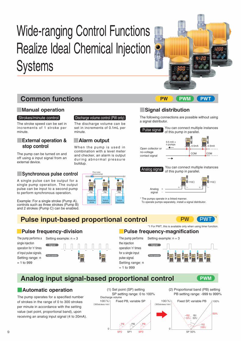
■Automatic operation
PWM PWTPW
PWMAnalog input signal-based proportional control
Common functions
Wide-ranging Control Functions Realize Ideal Chemical Injection Systems
The pump operates for a specified number of strokes in the range of 0 to 300 strokes per minute in accordance with the setting value (set point, proportional band), upon receiving an analog input signal (4 to 20mA).
Discharge volume
109
PWTPWPulse input-based proportional control
The pump performs the injection operation 'n' times for a single input pulse signal.Setting range: n = 1 to 999
The pump performs a single injection operation for 'n' times of input pulse signals.Setting range: n = 1 to 999
Signal
Pump operation
Signal
Pump operationECO
SAFE
PL
STOP
Manual1/n×n
strokes/minmL/minCAL
ECO
SAFE
PL
STOP
Manual1/n×n
strokes/minmL/minCAL
ECO
SAFE
PL
STOP
Manual1/n×n
strokes/minmL/minCAL
ECO
SAFE
PL
STOP
Manual1/n×n
strokes/minmL/minCAL
ECO
SAFE
PL
STOP
Manual1/n×n
strokes/minmL/minCAL
ECO
SAFE
PL
STOP
Manual1/n×n
strokes/minmL/minCAL
Setting example: n = 3
■Pulse frequency-magnificationSetting example: n = 3
■Pulse frequency-division
ECO
SAFE
PL
STOP
Manual1/n×n
strokes/minmL/minCAL
ECO
SAFE
PL
STOP
Manual1/n×n
strokes/minmL/minCAL
*1 For PWT, this is available only when using timer function.
*1
(1) Set point (SP) setting SP setting range: 0 to 100%
(2) Proportional band (PB) setting PB setting range: -999 to 999%
100(%)(300strokes/min)
SP1 SP3SP2
PB
Fixed PB, variable SP
0
PB PB
-PB2(-50%)
PB1(50%)
PB3(100%)
100(%)(300strokes/min)
SP 50%
50%
100%Fixed SP, variable PB
0
■Manual operation
■External operation & stop control
■Synchronous pulse control
■Alarm output
A single pulse can be output for a single pump operation. The output pulse can be input to a second pump to perform synchronous operation.
The pump can be turned on and off using a input signal from an external device.
W h e n t h e p u m p i s u s e d i n combination with a level meter and checker, an alarm is output d u r i n g a b n o r m a l p r e s s u r e buildup.
The stroke speed can be set in increments of 1 s t roke per minute.
The discharge volume can be set in increments of 0.1mL per minute.
* The pumps operate in a linked manner. To operate pumps separately, install a signal distributor.
The following connections are possible without usinga signal distributor.
■Signal distribution
You can connect multiple instancesof this pump in parallel.Pulse signal
You can connect multiple instancesof this pump in parallel.Analog signal
Analogsignal
+-
+
110Ω110Ω
- + -
ECO
SAFE
PL
STOP
Manual1/n×n
strokes/minmL/minCAL
ECO
SAFE
PL
STOP
Manual1/n×n
strokes/minmL/minCAL
Open collector orno-voltagecontact signal
COM
0.5mA
0.5 mA ×n pumps
COM
0.5mA
ECO
SAFE
PL
STOP
Manual1/n×n
strokes/minmL/minCAL
ECO
SAFE
PL
STOP
Manual1/n×n
strokes/minmL/minCAL
Example: For a single stroke (Pump A), controls such as three strokes (Pump B) and 2 strokes (Pump C) can be enabled.
PW
CBA
Flow meter(pulse/analog)
Sodiumhydroxide
Sodiumhypochlorite
Polyaluminum chloride
PWPW
ECO
SAFE
PL
STOP
Manual1/n×n
strokes/minmL/minCAL
ECO
SAFE
PL
STOP
Manual1/n×n
strokes/minmL/minCAL
ECO
SAFE
PL
STOP
Manual1/n×n
strokes/minmL/minCAL
Strokes/minute control Discharge volume control (PW only)
TM_00146571_P09_P10_1407_1_1C M Y K

No.1 Mon
Tue
Wed
Thu
Fri
Sat
Sun
ON time
OFF time
ON time
OFF time
ON time
OFF time
ON time
OFF time
ON time
OFF time
ON time
OFF time
ON time
OFF time
No.2
No.3
No.4
No.5
No.6
No.7
Mon0:00 12:00 12:00 12:00 12:00 12:00 12:00 12:00 12:00
Mon0:00
Tue0:00
Tue0:00
Wed0:00
Thu0:00
Fri0:00
Sat0:00
Sun0:00
24:00
9:00
30:00
36:00
‐‐:‐‐
36:00
32:00
18:009:00
12:00
9:00
‐‐:‐‐
12:00
0:00
Pump operation time
Time that can be set for each program
PWTTimer control
Item
Input signal
Output signal
Control
Digital
AnalogNumber of ports
Type
Digital
Number of strokes
Discharge volume control
Manual operation
Pulse proportional control
Analog proportional control
Timer control
External operation & stop input signal
Number of ports
Type
Setting example: ON period: 5 minutesOFF period: 3 minutes
The following combination of functions can also be used besides the abovementioned combination.
■Setting example
Setting example: ON time:OFF time:
The pump automatically operates every week at the same ON and OFF time being set for the day of the week.You can set one program pattern for each day of the week. You can set the ON time from 0:00 to 24:00 and OFF time within the range 0:00 to 48:00 in 1-minute unit.*WEEK mode cannot be used together with DAY mode.
Pump operation can be turned on and off in accordance with the setting of the timer. You can set any ON and OFF period for one pattern each in the range of 1 to 9999 minutes.
The pump operates automatically everyday using the same ON and OFF timing that is set. You can set up to nine program patterns within the range of 0:00 to 24:00 in 1-minute unit.*DAY mode cannot be used together with the WEEK mode.
PW (pulse type)
Stop signal, pulse signal
Sync pulse, alarm output
0.1 to maximum discharge volume (Enables setting in 0.1mL/minute units)
PWM (analog type)
Stop signal, pulse signal
Sync pulse, alarm output
1 to 300 (Enables setting in 1-stroke units)
PWT (timer type)
Sync pulse, alarm output
Stop signal, pulse signal
■WEEK mode
Interval mode
DAY mode Pulse proportional controlExternal operation control External operation control
External stop controlWEEK mode
+ + Interval mode Pulse proportional controlExternal stop control
DAY mode
WEEK mode+ + +
■Interval mode ■DAY mode
①1:00 ② 6:30 ③11:30 ④17:15①5:00 ②10:30 ③15:15 ④21:15
●When the pulse proportional control operation is set, the pump will operate in accordance with the pulse frequency-division or pulse frequency-magnification set for this operation.●When both interval mode and pulse proportional control operation are simultaneously set, the pump will operate in accordance with pulse frequency-division or pulse frequency-magnification set for this operation.*1*1 The number of strokes will be the value set in each program.
ON
5 minutes
STARTOFF
5 minutes 5 minutes
3 minutes 3 minutes 3 minutes3分
ON1:00
0:00 5:00
6:30
10:30
11:30 17:15
15:15 21:15 23:59OFF
●When both interval mode and pulse operation are simultaneously set, the pump will operate in accordance with pulse frequency-division or pulse frequency-magnification setting within the ON time set for the DAY mode and interval mode.
① ② ③ ④
PW
■Automatic operation
PWM PWTPW
PWMAnalog input signal-based proportional control
Common functions
Wide-ranging Control Functions Realize Ideal Chemical Injection Systems
The pump operates for a specified number of strokes in the range of 0 to 300 strokes per minute in accordance with the setting value (set point, proportional band), upon receiving an analog input signal (4 to 20mA).
Discharge volume
109
PWTPWPulse input-based proportional control
The pump performs the injection operation 'n' times for a single input pulse signal.Setting range: n = 1 to 999
The pump performs a single injection operation for 'n' times of input pulse signals.Setting range: n = 1 to 999
Signal
Pump operation
Signal
Pump operationECO
SAFE
PL
STOP
Manual1/n×n
strokes/minmL/minCAL
ECO
SAFE
PL
STOP
Manual1/n×n
strokes/minmL/minCAL
ECO
SAFE
PL
STOP
Manual1/n×n
strokes/minmL/minCAL
ECO
SAFE
PL
STOP
Manual1/n×n
strokes/minmL/minCAL
ECO
SAFE
PL
STOP
Manual1/n×n
strokes/minmL/minCAL
ECO
SAFE
PL
STOP
Manual1/n×n
strokes/minmL/minCAL
Setting example: n = 3
■Pulse frequency-magnificationSetting example: n = 3
■Pulse frequency-division
ECO
SAFE
PL
STOP
Manual1/n×n
strokes/minmL/minCAL
ECO
SAFE
PL
STOP
Manual1/n×n
strokes/minmL/minCAL
*1 For PWT, this is available only when using timer function.
*1
(1) Set point (SP) setting SP setting range: 0 to 100%
(2) Proportional band (PB) setting PB setting range: -999 to 999%
100(%)(300strokes/min)
SP1 SP3SP2
PB
Fixed PB, variable SP
0
PB PB
-PB2(-50%)
PB1(50%)
PB3(100%)
100(%)(300strokes/min)
SP 50%
50%
100%Fixed SP, variable PB
0
■Manual operation
■External operation & stop control
■Synchronous pulse control
■Alarm output
A single pulse can be output for a single pump operation. The output pulse can be input to a second pump to perform synchronous operation.
The pump can be turned on and off using a input signal from an external device.
W h e n t h e p u m p i s u s e d i n combination with a level meter and checker, an alarm is output d u r i n g a b n o r m a l p r e s s u r e buildup.
The stroke speed can be set in increments of 1 s t roke per minute.
The discharge volume can be set in increments of 0.1mL per minute.
* The pumps operate in a linked manner. To operate pumps separately, install a signal distributor.
The following connections are possible without usinga signal distributor.
■Signal distribution
You can connect multiple instancesof this pump in parallel.Pulse signal
You can connect multiple instancesof this pump in parallel.Analog signal
Analogsignal
+-
+
110Ω110Ω
- + -
ECO
SAFE
PL
STOP
Manual1/n×n
strokes/minmL/minCAL
ECO
SAFE
PL
STOP
Manual1/n×n
strokes/minmL/minCAL
Open collector orno-voltagecontact signal
COM
0.5mA
0.5 mA ×n pumps
COM
0.5mA
ECO
SAFE
PL
STOP
Manual1/n×n
strokes/minmL/minCAL
ECO
SAFE
PL
STOP
Manual1/n×n
strokes/minmL/minCAL
Example: For a single stroke (Pump A), controls such as three strokes (Pump B) and 2 strokes (Pump C) can be enabled.
PW
CBA
Flow meter(pulse/analog)
Sodiumhydroxide
Sodiumhypochlorite
Polyaluminum chloride
PWPW
ECO
SAFE
PL
STOP
Manual1/n×n
strokes/minmL/minCAL
ECO
SAFE
PL
STOP
Manual1/n×n
strokes/minmL/minCAL
ECO
SAFE
PL
STOP
Manual1/n×n
strokes/minmL/minCAL
Strokes/minute control Discharge volume control (PW only)
TM_00146571_P09_P10_1407_1_1C M Y K
PW
1211
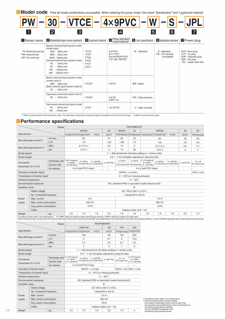
■Model code
■Performance specifications
1 2 6 73 54
30 JPLPW VTCE 4×9PVC W S
VTCEVTCFFTCEFTCFFTCT6TCT
W : Standard
[General chemical liquid injection model w/relief valve] 30R : 30mL/min 60R : 60mL/min 100R : 100mL/min[General chemical liquid injection model] 30 : 30mL/min 60 : 60mL/min 100 : 100mL/min 200 : 220mL/min*1
PW: Standard (pulse input) typePWM: Analog input typePWT: Timer control type
Series name1 Model(discharge volume standard)2 Liquid-end material3 Hose standard(size/material)4 Joint specification5 Applicable standard6 Power plug7
S : StandardCE : CE marking -compatible
EUP : Euro plugULP : UL plugAUP : Australia plugUKP : UK plugJPL : Japan lead wire
Max.discharge pressure*1
Stroke speed
Stroke length
Viscosity of transfer liquid
Temperature of transfer liquid
Ambient temperature
Environmental resistance
Insulation class
Power
supply
Weight
Connection
(hose/tube:I.D x O.D)
mL/min
L/H
MPa
bar
Discharge side
Suction side
Air-release
kg
30
1.8
27
1.62
0.5
5
1.8 1.8 1.8 3.2 1.9 1.9 1.9 1.9 1.9 3.3 1.9
0.7/1.0 *2
7/10 *2
4 x 9(PVC braidedhose)6 x 8(PE)
1/4"x3/8"(PE)
6 x 11(PVC braided hose)6 x 8(PE)
1/4" x 3/8"(PE)
6 x 8(PE)1/4"x3/8"(PE)
6 x 8(PE)1/4"x3/8"(PE)
6 x 8(FEP)1/4"x3/8"(FEP) 6 x 8(PTFE)
4 x 6 (soft PVC hose) 4 x 6 (soft PVC hose)
50mPa・s or less 3,000mPa・s or less*3
- -
6 x 8(FEP)1/4"x3/8"(FEP)
12 x 18(PVC braided hose)6 x 8(PTFE)
4 x 6(PA) 4 x 6(PA)
4 x 9(PVC braided hose) 4 x 9(PVC braided hose)
1~ 300 strokes/min (Enables setting in 1-stroke units)
0.5~ 1 mm (Enables adjustment using the dial)
0~ 40℃(no freezing allowed)
0~ 40℃IEC standard:IP65 or equivalent (water-&dust-proof)
B
AC 100 to 240 V (±10%)
1-phase/50 or 60 Hz
Cabtyre cable (φ5~10)
PW/PWM/PWT
VTCE/VTCF FTCE/FTCF FTCT 6TCT VTCE/VTCF FTCE/FTCF
60
3.6
0.7/1.0 *2
7/10 *2
FTCT 6TCT
55
3.3
0.5
5
VTCF(high-viscosity)
60
3.6
0.7
7
30R/30 30 30R/30
VTCET(boiler)
28
1.68
1.5
15
60R/60 606030
VTCET(high-pressure)
25
1.5
2
20
Model
Specification
[High-viscosity chemical liquid injection model] 60 : 60mL/min 100 : 100mL/min
[High-pressure chemical liquid injection model *2] 30 : 25mL/min
[Boiler chemical liquid injection model w/relief valve*2] 30R : 28mL/min[Boiler chemical liquid injection model*2] 30 : 28mL/min
VTCF
VTCET
VTCET
12×18 PVC
4×6 PAFNPT 1/4
4×9 PVC6×11 PVC6×8 PE/FEP/PTFE1/4"×3/8" PE/FEP
4×6 PA
V : High-viscosity
PW : High-pressure
BW : Boiler
Max.discharge volume*1
*1 Conditions:Clean water, room temperature. *2 0.7MPa (7bar) for models w/relief valve(R type) whereas 1.0MPa (10bar) for models w/o relief valve.*3 When transferring high-viscosity liquids, the maximum discharge volume may be lower than the specified volume depending on the characteristics of the liquid and operating conditions. Consult TACMINA separately when transferring high-viscosity liquids.
*1 Conditions:Clean water, room temperature.*2 When transferring high-viscosity liquids, the maximum discharge volume may be lower than the specified volume depending on the characteristics of the liquid and operating conditions. Consult TACMINA separately when transferring high-viscosity liquids.
*1 SAFE mode and ECO mode cannot be used. The information pertaining to liquid-end parts only applies to the VTCE/VTCF type. *2 SAFE mode cannot be used.
Max.discharge pressure*1
Stroke speed
Stroke length
Viscosity of transfer liquid
Temperature of transfer liquid
Ambient temperature
Environmental resistance
Insulation class
Power
supply
Weight
Connection
(hose/tube:I.D x O.D)
mL/min
L/H
MPa
bar
Discharge side
Suction side
Air-release
kg
100
6
95
5.7
0.5
5
100
6
0.7
7
1.9 1.9 1.9 3.3 1.9 4
0.7
7
6 x 11(PVC braided hose)6 x 8(PE)
1/4" x 3/8"(PE)
6 x 11(PVC braided hose)6 x 8(PE)
1/4" x 3/8"(PE)
6 x 8(PE)1/4"x3/8"(PE)
6 x 8(FEP)1/4"x3/8"(FEP)
12 x 18(PVC braided hose)6 x 8(PTFE)
4 x 6 (soft PVC hose)
50mPa・s or less 50mPa・s or less3,000mPa・s or less*2
- -
1~ 300 strokes/min (Enables setting in 1-stroke units)
0.5~ 1 mm (Enables adjustment using the dial)
0~ 40℃(no freezing allowed)
0~ 40℃IEC standard:IP65 or equivalent (water-&dust-proof)
B
AC 100 to 240 V (±10%)
1-phase/50 or 60 Hz
2.5 A
250 VA
18 W
Cabtyre cable (φ5~10)
PW/PWM/PWT
VTCE/VTCF FTCE/FTCF FTCT 6TCT VTCF(high-viscosity)
100R/100 100 100 200
VTCE/VTCF
220
13.2
0.2
2
Model
Specification
Max.discharge volume*1
*Not all model combinations are possible. When selecting the pump model, first check “Specification” and “Liguid-end material”.
■Liquid-end Material
PVC
UP
NEPO
ECO
SAFESAFESAFE
PL
STOP
Manual1/n×n
strokes/minmL/minCAL
118
16.5 75
(147)
74 7
34
140
87
87
R3
6
118
A
BC
D
D7697.5757676
A216237233230233
B152195167.5166169
C7697.592.59093
●PW/PWM/PWT/-30□/60□/100□ ●PW/PWM/PWT-200 ●PW/PWM/PWT/-30□/60□/100□ (6TCT)
ECO
SAFESAFESAFE
PL
STOP
Manual1/n×n
strokes/minmL/minCAL
118
(179)
22 98
(147)
74 7
34
169
(224.5)
84.5
84.5
140
87
87
R3
6
118
ECO
SAFESAFESAFE
PL
STOP
Manual1/n×n
strokes/minmL/minCAL
118
(150.5)
16.5 75
(147)
74 7
34
167.5
(233)
92.5
75
140
87
87
R3
6
118
* Also refer to the "Corrosion-resistance Table" on page 26.
■External dimensions
■Control function specifications
Model
PartVTCE
PVC
PTFE
Ceramic
EPDM
EPDM
---
PVC
PVC
---
---
Pump head
Diaphragm
Check ball
O-ring
Valve seat
Packing
Joint
Ball stopper
Valve stopper
Compression coil spring
VTCF
PVC
PTFE
Ceramic
Fluoro rubber
Special fluoro rubber
---
PVC
PVC
---
---
FTCE
PVDF
PTFE
Ceramic
EPDM
EPDM
---
PVDF, PP
PVDF
---
---
FTCF
PVDF
PTFE
Ceramic
Fluoro rubber
Special fluoro rubber
---
PVDF、PP
PVDF
---
---
FTCT
PVDF
PTFE
Ceramic
Special fluoro rubber
PTFE
PTFE
PVDF
PTFE
---
---
6TCT
SUS316
PTFE
Ceramic
PTFE
---
---
SUS316
---
PTFE
---
VTCF(High-viscosity)
PVC
PTFE
Ceramic
Fluoro rubber
---
---
PVC
---
PE
SUS304
VTCET(Boiler/High-pressure)
PVC
PTFE
Ceramic
EPDM
PTFE
---
PVC, SUS304
PVC
---
---
*1 This hose is already attached to models with the simple relief valve.*2 This hose is not supplied with 200-type models.*3 This accessory is supplied with models with the simple relief valve.* The signal cable is sold separately. The signal cable is included when the PWM and the chemical injection PTS series are purchased as a set.
■Accessories
---
---
---
---
3m
Item
PW/PWM/PWT
1m*2
---
1m
1set
1m---
1set
---
2m
2 sets (M5x30)
1copy
1set(R1/2)
11
1set
---
------
3m 3m 3m 3m
Discharge side: 2m
Suction side: 1m
Air purge hose with relief valve*1
Anti siphonal check valve
Foot valve
Ceramic weight
Hose pump
Signal cable
Pump attachment bolts and nuts
Instruction manual
Hose / Tube
Cable ties (INSULOK®) for relief hose (spare)*3
General chemical model Boiler High pressure
VTCE VTCF FTCE FTCF VTCET6TCTFTCT VTCET
1 set (R1/2 or R3/8)
High viscosity
VTCF
PWM
---
---
---
---
---
---
---
---
---
○
○
○
○
○
PWT
---
---
---
---
1 pattern (1~9999min.)
9pattern
7pattern
○
○
1/999~1/1
1~999
○
○
○
○
PW
1/999~1/1
1~999
---
---
---
---
---
---
---
---
○
○
○
○
Item
Signal
Control
Digital
Manualoperation
Timer
Input
Output
Number of strokes
Division
Magnification
Interval
DAY
WEEK
DAY + Interval
WEEK + Interval
Division
Magnification
1 to 300 (Enables setting in 1-stroke units)
Timer + Pulse proportional
control
Analog input
Analog proportional control
0.1 to maximumdischarge volume
(Setting in 0.1mL/min. units enabled)
One port: pulse signal(no-voltage contact or open collector,
maximum no. of pulses: 1200 pulses/minute, minimum pulse width: 25 ms [ON period])
One port: pump stop signal(no-voltage contact or open collector,
maximum no. of pulses: 1200 pulses/minute, minimum pulse width: 25 ms [ON period])
One port: pump stop signal (no-voltage
contact or open collector, maximum no. of pulses:
1200 pulses/minute, minimum pulse width:
25 ms [ON period])
One port: solenoid sync pulse signal(DC 25 V, 10 mA or less)
One port: batch warning signal(DC 25 V, 10 mA or less)
One port: analog signal (DC 4 to 20 mA, input resistance:
approximately 110 Ω)
Proportional band/set point method
---
External operation signal
External stop signal
Operation sync pulse
Alarm output
1set(R1/2)
Dischargevolume control
Pulseproportional
control
* The shape and dimensions differ slightly depending on the liguid-end material and connection type.
VTCE/VTCFFTCE/FTCF/FTCTVTCF (High viscosity)VTCET(BWJ)VTCET(PWJ)
Rated voltage
No. of phases/Frequency
Max. current
Max. power consumption
Avg. power consumption
Cable
Rated voltage
No. of phases/Frequency
Max. current
Max. power consumption
Avg. power consumption
Cable
2 A
200 VA
15 W
2.5 A
250 VA
18 W
TM_00146571_P11_P12_1407_1_1C M Y K

PW
1211
■Model code
■Performance specifications
1 2 6 73 54
30 JPLPW VTCE 4×9PVC W S
VTCEVTCFFTCEFTCFFTCT6TCT
W : Standard
[General chemical liquid injection model w/relief valve] 30R : 30mL/min 60R : 60mL/min 100R : 100mL/min[General chemical liquid injection model] 30 : 30mL/min 60 : 60mL/min 100 : 100mL/min 200 : 220mL/min*1
PW: Standard (pulse input) typePWM: Analog input typePWT: Timer control type
Series name1 Model(discharge volume standard)2 Liquid-end material3 Hose standard(size/material)4 Joint specification5 Applicable standard6 Power plug7
S : StandardCE : CE marking -compatible
EUP : Euro plugULP : UL plugAUP : Australia plugUKP : UK plugJPL : Japan lead wire
Max.discharge pressure*1
Stroke speed
Stroke length
Viscosity of transfer liquid
Temperature of transfer liquid
Ambient temperature
Environmental resistance
Insulation class
Power
supply
Weight
Connection
(hose/tube:I.D x O.D)
mL/min
L/H
MPa
bar
Discharge side
Suction side
Air-release
kg
30
1.8
27
1.62
0.5
5
1.8 1.8 1.8 3.2 1.9 1.9 1.9 1.9 1.9 3.3 1.9
0.7/1.0 *2
7/10 *2
4 x 9(PVC braidedhose)6 x 8(PE)
1/4"x3/8"(PE)
6 x 11(PVC braided hose)6 x 8(PE)
1/4" x 3/8"(PE)
6 x 8(PE)1/4"x3/8"(PE)
6 x 8(PE)1/4"x3/8"(PE)
6 x 8(FEP)1/4"x3/8"(FEP) 6 x 8(PTFE)
4 x 6 (soft PVC hose) 4 x 6 (soft PVC hose)
50mPa・s or less 3,000mPa・s or less*3
- -
6 x 8(FEP)1/4"x3/8"(FEP)
12 x 18(PVC braided hose)6 x 8(PTFE)
4 x 6(PA) 4 x 6(PA)
4 x 9(PVC braided hose) 4 x 9(PVC braided hose)
1~ 300 strokes/min (Enables setting in 1-stroke units)
0.5~ 1 mm (Enables adjustment using the dial)
0~ 40℃(no freezing allowed)
0~ 40℃IEC standard:IP65 or equivalent (water-&dust-proof)
B
AC 100 to 240 V (±10%)
1-phase/50 or 60 Hz
Cabtyre cable (φ5~10)
PW/PWM/PWT
VTCE/VTCF FTCE/FTCF FTCT 6TCT VTCE/VTCF FTCE/FTCF
60
3.6
0.7/1.0 *2
7/10 *2
FTCT 6TCT
55
3.3
0.5
5
VTCF(high-viscosity)
60
3.6
0.7
7
30R/30 30 30R/30
VTCET(boiler)
28
1.68
1.5
15
60R/60 606030
VTCET(high-pressure)
25
1.5
2
20
Model
Specification
[High-viscosity chemical liquid injection model] 60 : 60mL/min 100 : 100mL/min
[High-pressure chemical liquid injection model *2] 30 : 25mL/min
[Boiler chemical liquid injection model w/relief valve*2] 30R : 28mL/min[Boiler chemical liquid injection model*2] 30 : 28mL/min
VTCF
VTCET
VTCET
12×18 PVC
4×6 PAFNPT 1/4
4×9 PVC6×11 PVC6×8 PE/FEP/PTFE1/4"×3/8" PE/FEP
4×6 PA
V : High-viscosity
PW : High-pressure
BW : Boiler
Max.discharge volume*1
*1 Conditions:Clean water, room temperature. *2 0.7MPa (7bar) for models w/relief valve(R type) whereas 1.0MPa (10bar) for models w/o relief valve.*3 When transferring high-viscosity liquids, the maximum discharge volume may be lower than the specified volume depending on the characteristics of the liquid and operating conditions. Consult TACMINA separately when transferring high-viscosity liquids.
*1 Conditions:Clean water, room temperature.*2 When transferring high-viscosity liquids, the maximum discharge volume may be lower than the specified volume depending on the characteristics of the liquid and operating conditions. Consult TACMINA separately when transferring high-viscosity liquids.
*1 SAFE mode and ECO mode cannot be used. The information pertaining to liquid-end parts only applies to the VTCE/VTCF type. *2 SAFE mode cannot be used.
Max.discharge pressure*1
Stroke speed
Stroke length
Viscosity of transfer liquid
Temperature of transfer liquid
Ambient temperature
Environmental resistance
Insulation class
Power
supply
Weight
Connection
(hose/tube:I.D x O.D)
mL/min
L/H
MPa
bar
Discharge side
Suction side
Air-release
kg
100
6
95
5.7
0.5
5
100
6
0.7
7
1.9 1.9 1.9 3.3 1.9 4
0.7
7
6 x 11(PVC braided hose)6 x 8(PE)
1/4" x 3/8"(PE)
6 x 11(PVC braided hose)6 x 8(PE)
1/4" x 3/8"(PE)
6 x 8(PE)1/4"x3/8"(PE)
6 x 8(FEP)1/4"x3/8"(FEP)
12 x 18(PVC braided hose)6 x 8(PTFE)
4 x 6 (soft PVC hose)
50mPa・s or less 50mPa・s or less3,000mPa・s or less*2
- -
1~ 300 strokes/min (Enables setting in 1-stroke units)
0.5~ 1 mm (Enables adjustment using the dial)
0~ 40℃(no freezing allowed)
0~ 40℃IEC standard:IP65 or equivalent (water-&dust-proof)
B
AC 100 to 240 V (±10%)
1-phase/50 or 60 Hz
2.5 A
250 VA
18 W
Cabtyre cable (φ5~10)
PW/PWM/PWT
VTCE/VTCF FTCE/FTCF FTCT 6TCT VTCF(high-viscosity)
100R/100 100 100 200
VTCE/VTCF
220
13.2
0.2
2
Model
Specification
Max.discharge volume*1
*Not all model combinations are possible. When selecting the pump model, first check “Specification” and “Liguid-end material”.
■Liquid-end Material
PVC
UP
NEPO
ECO
SAFESAFESAFE
PL
STOP
Manual1/n×n
strokes/minmL/minCAL
118
16.5 75
(147)
74 7
34
140
87
87
R3
6
118
A
BC
D
D7697.5757676
A216237233230233
B152195167.5166169
C7697.592.59093
●PW/PWM/PWT/-30□/60□/100□ ●PW/PWM/PWT-200 ●PW/PWM/PWT/-30□/60□/100□ (6TCT)
ECO
SAFESAFESAFE
PL
STOP
Manual1/n×n
strokes/minmL/minCAL
118
(179)
22 98
(147)
74 7
34
169
(224.5)
84.5
84.5
140
87
87
R3
6
118
ECO
SAFESAFESAFE
PL
STOP
Manual1/n×n
strokes/minmL/minCAL
118
(150.5)
16.5 75
(147)
74 7
34
167.5
(233)
92.5
75
140
87
87
R3
6
118
* Also refer to the "Corrosion-resistance Table" on page 26.
■External dimensions
■Control function specifications
Model
PartVTCE
PVC
PTFE
Ceramic
EPDM
EPDM
---
PVC
PVC
---
---
Pump head
Diaphragm
Check ball
O-ring
Valve seat
Packing
Joint
Ball stopper
Valve stopper
Compression coil spring
VTCF
PVC
PTFE
Ceramic
Fluoro rubber
Special fluoro rubber
---
PVC
PVC
---
---
FTCE
PVDF
PTFE
Ceramic
EPDM
EPDM
---
PVDF, PP
PVDF
---
---
FTCF
PVDF
PTFE
Ceramic
Fluoro rubber
Special fluoro rubber
---
PVDF、PP
PVDF
---
---
FTCT
PVDF
PTFE
Ceramic
Special fluoro rubber
PTFE
PTFE
PVDF
PTFE
---
---
6TCT
SUS316
PTFE
Ceramic
PTFE
---
---
SUS316
---
PTFE
---
VTCF(High-viscosity)
PVC
PTFE
Ceramic
Fluoro rubber
---
---
PVC
---
PE
SUS304
VTCET(Boiler/High-pressure)
PVC
PTFE
Ceramic
EPDM
PTFE
---
PVC, SUS304
PVC
---
---
*1 This hose is already attached to models with the simple relief valve.*2 This hose is not supplied with 200-type models.*3 This accessory is supplied with models with the simple relief valve.* The signal cable is sold separately. The signal cable is included when the PWM and the chemical injection PTS series are purchased as a set.
■Accessories
---
---
---
---
3m
Item
PW/PWM/PWT
1m*2
---
1m
1set
1m---
1set
---
2m
2 sets (M5x30)
1copy
1set(R1/2)
11
1set
---
------
3m 3m 3m 3m
Discharge side: 2m
Suction side: 1m
Air purge hose with relief valve*1
Anti siphonal check valve
Foot valve
Ceramic weight
Hose pump
Signal cable
Pump attachment bolts and nuts
Instruction manual
Hose / Tube
Cable ties (INSULOK®) for relief hose (spare)*3
General chemical model Boiler High pressure
VTCE VTCF FTCE FTCF VTCET6TCTFTCT VTCET
1 set (R1/2 or R3/8)
High viscosity
VTCF
PWM
---
---
---
---
---
---
---
---
---
○
○
○
○
○
PWT
---
---
---
---
1 pattern (1~9999min.)
9pattern
7pattern
○
○
1/999~1/1
1~999
○
○
○
○
PW
1/999~1/1
1~999
---
---
---
---
---
---
---
---
○
○
○
○
Item
Signal
Control
Digital
Manualoperation
Timer
Input
Output
Number of strokes
Division
Magnification
Interval
DAY
WEEK
DAY + Interval
WEEK + Interval
Division
Magnification
1 to 300 (Enables setting in 1-stroke units)
Timer + Pulse proportional
control
Analog input
Analog proportional control
0.1 to maximumdischarge volume
(Setting in 0.1mL/min. units enabled)
One port: pulse signal(no-voltage contact or open collector,
maximum no. of pulses: 1200 pulses/minute, minimum pulse width: 25 ms [ON period])
One port: pump stop signal(no-voltage contact or open collector,
maximum no. of pulses: 1200 pulses/minute, minimum pulse width: 25 ms [ON period])
One port: pump stop signal (no-voltage
contact or open collector, maximum no. of pulses:
1200 pulses/minute, minimum pulse width:
25 ms [ON period])
One port: solenoid sync pulse signal(DC 25 V, 10 mA or less)
One port: batch warning signal(DC 25 V, 10 mA or less)
One port: analog signal (DC 4 to 20 mA, input resistance:
approximately 110 Ω)
Proportional band/set point method
---
External operation signal
External stop signal
Operation sync pulse
Alarm output
1set(R1/2)
Dischargevolume control
Pulseproportional
control
* The shape and dimensions differ slightly depending on the liguid-end material and connection type.
VTCE/VTCFFTCE/FTCF/FTCTVTCF (High viscosity)VTCET(BWJ)VTCET(PWJ)
Rated voltage
No. of phases/Frequency
Max. current
Max. power consumption
Avg. power consumption
Cable
Rated voltage
No. of phases/Frequency
Max. current
Max. power consumption
Avg. power consumption
Cable
2 A
200 VA
15 W
2.5 A
250 VA
18 W
TM_00146571_P11_P12_1407_1_1C M Y K

Direct Entry of Injection AmountThe injection amount can be set according to three patterns:[By stroke speed] Setting range: 1 to 300 strokes/min (minimum setting increment: 1 stroke/min)
[By discharge volume] Setting range: 0.1 to (maximum discharge volume of selected model) mL/min (minimum setting increment: 0.1 mL/min)
[By percentage] Setting range: 1 to 100% (minimum setting increment: 1% (3 strokes/min))
6TCTMaterial: Stainless steel (SUS316.304)Application example:Transfer/ inject ion ofsolutions/special chemicals
Extensive Range of Liquid-end Materials
VTCE/VTCFMaterial: PVCApplication example:Transfer/ inject ion ofgeneral chemicals
FTCTMaterial: PVDFApplication example:Transfer/ inject ion ofspecial chemicals(e.g. strong and mixed acids)
VTCF(high-viscosity type*)Material: PVCApplication example:Transfer/ inject ion ofhigh-viscosity liquids
Simple Key Layout
STROKE LENGTH
100%0
90
8020
60 40 50
7030
Stroke-lengthadjustment dial
Stroke-lengthadjustment dial
LCD panelSTART/STOP keyMODE keyUP keyDOWN key
Pilot lamp
* Provided for PZD series only.
3-directional Pump Head
Separate-type Head & Controller
This feature is limited depending on the operating conditions. Consult us for details.
OutdoorUse
Water- & Dust-proofSpecifications
IEC standard: IP65 or equivalent Avoid condensation and immersion in water.
PZi
w/ backlight*
STROKE LENGTH
100%0
90
8020
60 40 50
7030
* Backlight is provided only on PZi8.
PZD
LCD panel
START/STOP keyMODE keyUP keyDOWN key
Pilot lamp
PZ
i/P
ZD
Common Functions PZi4 |PZi8
PZi4 |PZi8
PZi4PZi8
PZi4 |PZi8PZD
PZi8
No-inputPZD
PZDDigital Setting
Digital-input & Analog-inputPZi4Digital-input/output & Analog-inputPZi8
PZiDigital Setting
Advanced Functions
AC100 240V( 10%)Wide VoltageRange Power Supply
There is no need to worry about sitepower supply voltage or voltage fluctuationssince it can be used with AC100 to 240 V( 10%) power supplies. You can also keep it instock safely since it can be used for a variety of sites and applications.
* When transferring high-viscosity liquids, the maximum discharge volume may be lower than the specified volume depending on the characteristics of the liquid and operating conditions. Consult TACMINA separately when transferring high-viscosity liquids.
High-viscosity The PZD series can also be used for theinjection of polymer coagulant.
Max.3000mPa・s
■External operation & stop control
The pump can be turned on and off using a input signal from an external device.
PZi4PZi8
Chemical liquid tank
Level meter
Pulse-Input Proportional Control & External Stop Input ControlPump ON/OFF can be controlled by an external stop input signal.Also, the injection amount (1/9999 to 9999 strokes/pulse) can beset according to the pulse input signal from an external device.
For details on the Level Switch, see "Option" on the back cover.
Main piping
Pulse-transmitting flow meter
Level Switch
Quick & Easy CalibrationThe PZD Series is provided with easy calibration functionfor accurate pump calibration. Just push the button to automatically discharge 300 strokes' worth of chemicaland enter the actual discharge volume that you will bemeasuring. This is all you need to do for accurate calibration.
PP
PZi
Residualchlorine meter
PP
INV.
Residualchlorine meter
PP
Controller
Controller Controller
pH meter ControllerpH meter
PZi
INV.
Conventional system
Conventional system
C
C C
CpH pH
R R
P
P
Analog-Input Proportional ControlThe injection amount (stroke frequency: 0 to 300 strokes/min)can be set according to the analog input signal (PZi4: 4 to 20 mA,PZ i8: 0 to 20 mA or 4 to 20 mA) from an ex ter nal dev ice.
.Inverter required
.Narrow control range of 1:10 (6 to 60 Hz)
.Raw liquid must be diluted since the discharge volume per stroke is large.
.Inverter not required
.Wide control range of 1:300 (1 to 300 strokes/min)
.Raw liquid can be injected since the discharge volume per stroke is small.
Motor Driven Pump PZi
pH Control
PZi
PZi
Residual Chlorine Control
2-point Level Switch ControlControl such as alarm displayand output, and pump stopis performed in accordancewith the remaining amountof chemicals.
Count (batch) & Interval (timer) OperationCount setting
1 to 9999 strokes(x1, x10, x100, x1000)
Interval setting
ON time : 1 to 9999 minOFF time : 1 to 9999 min
Start/Stop signal
PZi8
PZi8
2-point Level Switch
1413
Mid
dle
Ca
pa
cit
y
TM_00146571_P13_P14_1407_1_1C M Y K
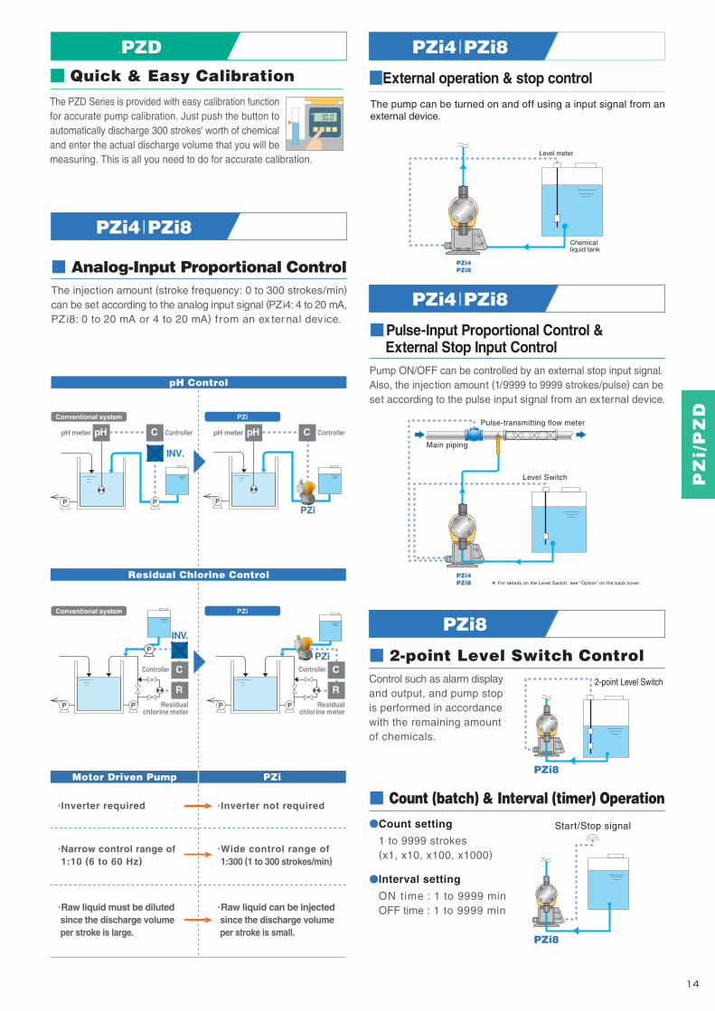
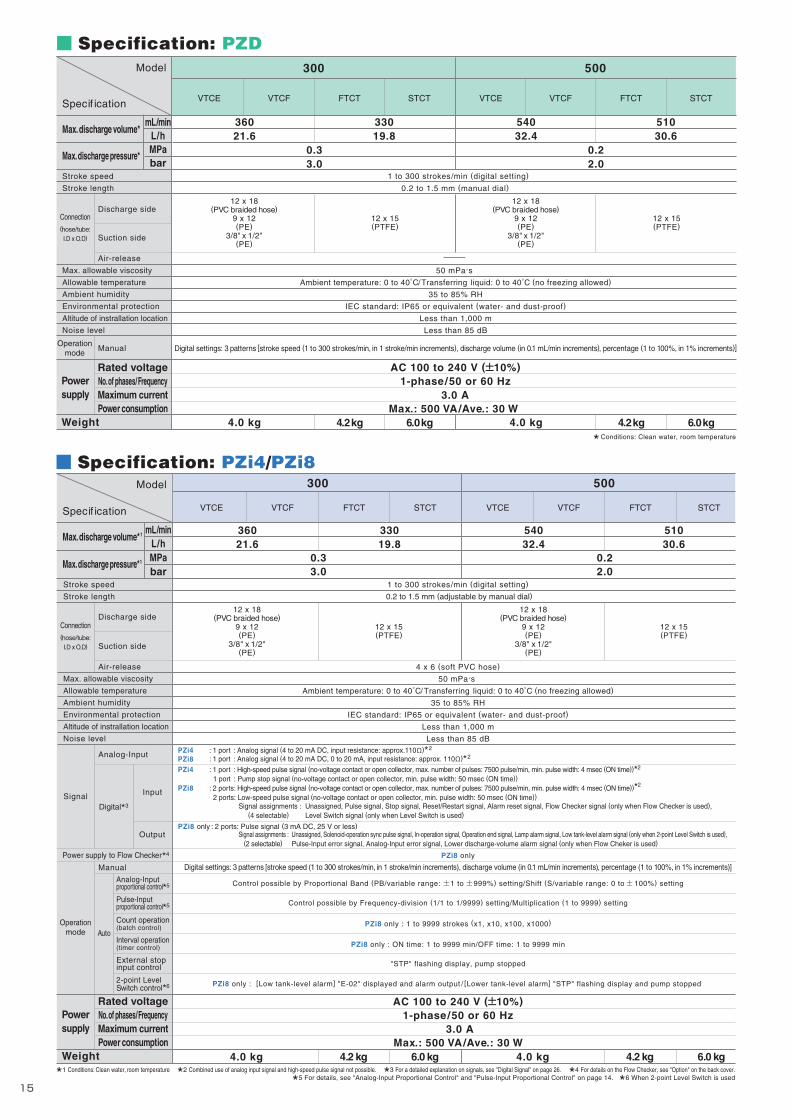
87
R3
876
68
102
7
31
155(A)
(150)
E
G
(F)φ118
BD
C
87
R3
876
102
150
7155
(A)
31
68 G
(F)φ118
B
DC
E
●PZD ●PZi4/PZi8
Specification: PZD
1 to 300 strokes/min (digital setting)
36021.6
33019.8
51030.6
54032.4
0.33.0
0.22.0
300 500
0.2 to 1.5 mm (manual dial)
VTCE VTCF FTCT STCT VTCE VTCF FTCT STCT
3.0 AMax.: 500 VA/Ave.: 30 W
4.0 kg 4.2 kg 6.0 kg 6.0 kg4.0 kg 4.2 kg
* Conditions: Clean water, room temperature
Specif ication
Model
mL/minL/hMPabar
Stroke speed
Stroke length
Max. allowable viscosity
Allowable temperature
Ambient humidity
Environmental protection
Altitude of instrallation location
Noise level
Max. discharge volume*
Max. discharge pressure*
Connection(hose/tube:
I.D x O.D)
Discharge side
Suction side
Air-release
ManualOperation
mode
Rated voltageNo. of phases/FrequencyMaximum currentPower consumption
Powersupply
Weight
12 x 18(PVC braided hose)
9 x 12(PE)
3/8" x 1/2"(PE)
12 x 15(PTFE)
12 x 18(PVC braided hose)
9 x 12(PE)
3/8" x 1/2"(PE)
12 x 15(PTFE)
50 mPa.s
Ambient temperature: 0 to 40 /Transferring liquid: 0 to 40 (no freezing allowed)
35 to 85% RH
IEC standard: IP65 or equivalent (water- and dust-proof)
Less than 1,000 m
Less than 85 dB
Digital settings: 3 patterns [stroke speed (1 to 300 strokes/min, in 1 stroke/min increments), discharge volume (in 0.1 mL/min increments), percentage (1 to 100%, in 1% increments)]
AC 100 to 240 V ( 10%)1-phase/50 or 60 Hz
1 to 300 strokes/min (digital setting)
0.2 to 1.5 mm (adjustable by manual dial)
6.0 kg4.2 kg4.0 kg 6.0 kg4.2 kg4.0 kg
PZi8 only
Control possible by Proportional Band (PB/variable range: 1 to 999%) setting/Shift (S/variable range: 0 to 100%) setting
Control possible by Frequency-division (1/1 to 1/9999) setting/Multiplication (1 to 9999) setting
PZi8 only : 1 to 9999 strokes (x1, x10, x100, x1000)
PZi8 only : ON time: 1 to 9999 min/OFF time: 1 to 9999 min
"STP" flashing display, pump stopped
PZi8 only : [Low tank-level alarm] "E-02" displayed and alarm output / [Lower tank-level alarm] "STP" flashing display and pump stopped
0.33.0
0.22.0
36021.6
33019.8
51030.6
54032.4
300 500
VTCE VTCF FTCT STCT VTCE VTCF FTCT STCT
Stroke speed
Stroke length
Max. allowable viscosity
Allowable temperature
Ambient humidity
Environmental protection
Altitude of instrallation location
Noise level
*1 Conditions: Clean water, room temperature *2 Combined use of analog input signal and high-speed pulse signal not possible. *3 For a detailed explanation on signals, see "Digital Signal" on page 26. *4 For details on the Flow Checker, see "Option" on the back cover.
*5 For details, see "Analog-Input Proportional Control" and "Pulse-Input Proportional Control" on page 14. *6 When 2-point Level Switch is used
Specification: PZi4/PZi8
Analog-Inputproportional control*5
Pulse-Inputproportional control*5
Count operation(batch control)
Interval operation(timer control)
External stopinput control
2-point LevelSwitch control
Operationmode Auto
mL/minL/hMPabar
Specif ication
Model
Max. discharge volume*1
Max. discharge pressure*1
Connection(hose/tube:
I.D x O.D)
Discharge side
Suction side
Air-release
Power supply to Flow Checker*4
Rated voltageNo. of phases/FrequencyMaximum currentPower consumption
Powersupply
Weight
Manual
SignalDigital*3
Input
Output
Analog-Input
4 x 6 (soft PVC hose)
50 mPa.s
Ambient temperature: 0 to 40 /Transferring liquid: 0 to 40 (no freezing allowed)
35 to 85% RH
IEC standard: IP65 or equivalent (water- and dust-proof)
Less than 1,000 m
Less than 85 dB
Digital settings: 3 patterns [stroke speed (1 to 300 strokes/min, in 1 stroke/min increments), discharge volume (in 0.1 mL/min increments), percentage (1 to 100%, in 1% increments)]
AC 100 to 240 V ( 10%)1-phase/50 or 60 Hz
3.0 AMax.: 500 VA/Ave.: 30 W
12 x 18(PVC braided hose)
9 x 12(PE)
3/8" x 1/2"(PE)
12 x 15(PTFE)
12 x 18(PVC braided hose)
9 x 12(PE)
3/8" x 1/2"(PE)
12 x 15(PTFE)
*6
PZi4 : 1 port : Analog signal (4 to 20 mA DC, input resistance: approx.110 )*2
PZi8 : 1 port : Analog signal (4 to 20 mA DC, 0 to 20 mA, input resistance: approx. 110 )*2
PZi4 : 1 port : High-speed pulse signal (no-voltage contact or open collector, max. number of pulses: 7500 pulse/min, min. pulse width: 4 msec (ON time))*2
1 port : Pump stop signal (no-voltage contact or open collector, min. pulse width: 50 msec (ON time))PZi8 : 2 ports: High-speed pulse signal (no-voltage contact or open collector, max. number of pulses: 7500 pulse/min, min. pulse width: 4 msec (ON time))*2
2 ports: Low-speed pulse signal (no-voltage contact or open collector, min. pulse width: 50 msec (ON time))Signal assignments : Unassigned, Pulse signal, Stop signal, Reset/Restart signal, Alarm reset signal, Flow Checker signal (only when Flow Checker is used), (4 selectable) Level Switch signal (only when Level Switch is used)
PZi8 only : 2 ports: Pulse signal (3 mA DC, 25 V or less)Signal assignments : Unassigned, Solenoid-operation sync pulse signal, In-operation signal, Operation end signal, Lamp alarm signal, Low tank-level alarm signal (only when 2-point Level Switch is used), (2 selectable) Pulse-Input error signal, Analog-Input error signal, Lower discharge-volume alarm signal (only when Flow Cheker is used)
*1 For details on the hose/tube aperture, see "Connection" for the respective model in "Specification" table above. *2 Only when PE tube is selected
VTCE VTCF FTCT STCT
1 set(R1/2 or R3/8)
PZD
3 m
Accessory
Hose/ Tube*1
Anti-siphon check valve
Foot valve
Ceramic weight
Pump mounting nuts / bolts
Operation manual
Item
Model
1 set
1 set(R1/2)
2 sets (M5 x 30)
1 set
1 set*2
VTCE VTCF FTCT STCT
PZi4/PZi8
1 set(R1/2 or R3/8)
3 m
1 set
1 set(R1/2)
1 set*2
PZ
i/P
ZD
1615
VTCE/VTCF
FTCT/STCT
(A) B C D E (F) G243
255.5
281.5
176
183
253
88
82.5
126.5
88
100.5
126.5
24.5
22
26
180
174.5
181
85.5
83
85.5
VTCE/VTCF
FTCT/STCT
(A) B C D E (F) G243
255.5
176
183
88
82.5
88
100.5
24.5
22
180
174.5
85.5
83
ModelModel
The shape and dimensions differ slightly depending on the liquid-end material and connection type.The mounting pitch allows mounting from 87 to 110 mm.
VTCF(High-viscosity)
1 4 5 632
Model Code Not all model combinations are possible. When selecting the pump model, f irst check "Specif ication" and "Liquid-end Material".
PZD 30R VTCE 4x9PVC W S JPL
[for injection of general chemicals]Model (discharge volume standard)1 Joint specification4 Applicable standard5 Power plug6Hose standard (size/material)3Liquid-end material2
300 : 300 mL/min500 : 500 mL/min
VTCEVTCFFTCTSTCT
12 x 18 PVC9 x 12 PE
3/8" x 1/2" PE12 x 15 PTFE
W : Standard S : StandardCE : CE marking-compatible
EUP : Euro plugULP : UL plugAUP : Australia plugUKP : UK plugJPL : Japan lead wireNON : No Cable
21 5 6 743Model (discharge volume standard)2 Joint specification5 Applicable standard6Hose standard (size/material)4Liquid-end material3Series name1
[for injection of general chemicals]Power plug7
EUP : Euro plugULP : UL plugAUP : Australia plugUKP : UK plugJPL : Japan lead wireNON : No Cable
300 : 300 mL/min500 : 500 mL/min
PZi4 : Analog/ Digital-InputPZi8 : Analog/ Digital-Input & Digital-Output
VTCEVTCFFTCTSTCT
12 x 18 PVC9 x 12 PE
3/8" x 1/2" PE12 x 15 PTFE
W : Standard S : StandardCE : CE marking-compatible
PZi8 30R VTCE 4x9PVC W S JPL
External Dimension (mm)
SUS304
SUS304
VTCE VTCF FTCT STCT(L-size)
Also refer to the "Corrosion-resistance Table" on page 26.
When "NON" is selected for power plug, the power cable(2m) is not provided.
Liquid-end Material
PartModel
Pump head
Diaphragm
Check ball
O-ring
Valve seat
Joint
Ball stopper
PVC
PVC
PVC
EPDM
EPDM
Fluoro-rubber
Special fluoro-rubber
PTFE
Ceramic
PVDF
PTFE
PVDF
PTFE
PTFE (valve stopper)
TM_00146571_P15_P16_1407_1_1C M Y K
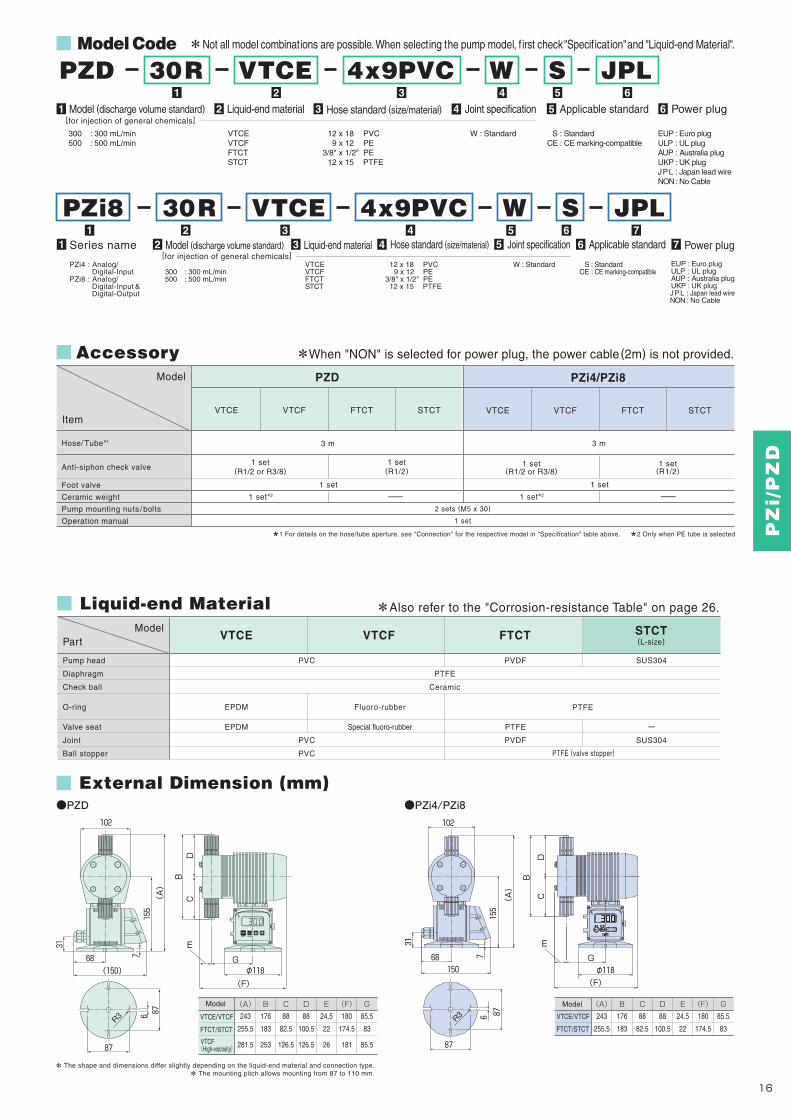
87
R3
876
68
102
7
31
155(A)
(150)
E
G
(F)φ118
BD
C
87
R3
876
102
150
7155
(A)
31
68 G
(F)φ118
B
DC
E
●PZD ●PZi4/PZi8
Specification: PZD
1 to 300 strokes/min (digital setting)
36021.6
33019.8
51030.6
54032.4
0.33.0
0.22.0
300 500
0.2 to 1.5 mm (manual dial)
VTCE VTCF FTCT STCT VTCE VTCF FTCT STCT
3.0 AMax.: 500 VA/Ave.: 30 W
4.0 kg 4.2 kg 6.0 kg 6.0 kg4.0 kg 4.2 kg
* Conditions: Clean water, room temperature
Specif ication
Model
mL/minL/hMPabar
Stroke speed
Stroke length
Max. allowable viscosity
Allowable temperature
Ambient humidity
Environmental protection
Altitude of instrallation location
Noise level
Max. discharge volume*
Max. discharge pressure*
Connection(hose/tube:
I.D x O.D)
Discharge side
Suction side
Air-release
ManualOperation
mode
Rated voltageNo. of phases/FrequencyMaximum currentPower consumption
Powersupply
Weight
12 x 18(PVC braided hose)
9 x 12(PE)
3/8" x 1/2"(PE)
12 x 15(PTFE)
12 x 18(PVC braided hose)
9 x 12(PE)
3/8" x 1/2"(PE)
12 x 15(PTFE)
50 mPa.s
Ambient temperature: 0 to 40 /Transferring liquid: 0 to 40 (no freezing allowed)
35 to 85% RH
IEC standard: IP65 or equivalent (water- and dust-proof)
Less than 1,000 m
Less than 85 dB
Digital settings: 3 patterns [stroke speed (1 to 300 strokes/min, in 1 stroke/min increments), discharge volume (in 0.1 mL/min increments), percentage (1 to 100%, in 1% increments)]
AC 100 to 240 V ( 10%)1-phase/50 or 60 Hz
1 to 300 strokes/min (digital setting)
0.2 to 1.5 mm (adjustable by manual dial)
6.0 kg4.2 kg4.0 kg 6.0 kg4.2 kg4.0 kg
PZi8 only
Control possible by Proportional Band (PB/variable range: 1 to 999%) setting/Shift (S/variable range: 0 to 100%) setting
Control possible by Frequency-division (1/1 to 1/9999) setting/Multiplication (1 to 9999) setting
PZi8 only : 1 to 9999 strokes (x1, x10, x100, x1000)
PZi8 only : ON time: 1 to 9999 min/OFF time: 1 to 9999 min
"STP" flashing display, pump stopped
PZi8 only : [Low tank-level alarm] "E-02" displayed and alarm output / [Lower tank-level alarm] "STP" flashing display and pump stopped
0.33.0
0.22.0
36021.6
33019.8
51030.6
54032.4
300 500
VTCE VTCF FTCT STCT VTCE VTCF FTCT STCT
Stroke speed
Stroke length
Max. allowable viscosity
Allowable temperature
Ambient humidity
Environmental protection
Altitude of instrallation location
Noise level
*1 Conditions: Clean water, room temperature *2 Combined use of analog input signal and high-speed pulse signal not possible. *3 For a detailed explanation on signals, see "Digital Signal" on page 26. *4 For details on the Flow Checker, see "Option" on the back cover.
*5 For details, see "Analog-Input Proportional Control" and "Pulse-Input Proportional Control" on page 14. *6 When 2-point Level Switch is used
Specification: PZi4/PZi8
Analog-Inputproportional control*5
Pulse-Inputproportional control*5
Count operation(batch control)
Interval operation(timer control)
External stopinput control
2-point LevelSwitch control
Operationmode Auto
mL/minL/hMPabar
Specif ication
Model
Max. discharge volume*1
Max. discharge pressure*1
Connection(hose/tube:
I.D x O.D)
Discharge side
Suction side
Air-release
Power supply to Flow Checker*4
Rated voltageNo. of phases/FrequencyMaximum currentPower consumption
Powersupply
Weight
Manual
SignalDigital*3
Input
Output
Analog-Input
4 x 6 (soft PVC hose)
50 mPa.s
Ambient temperature: 0 to 40 /Transferring liquid: 0 to 40 (no freezing allowed)
35 to 85% RH
IEC standard: IP65 or equivalent (water- and dust-proof)
Less than 1,000 m
Less than 85 dB
Digital settings: 3 patterns [stroke speed (1 to 300 strokes/min, in 1 stroke/min increments), discharge volume (in 0.1 mL/min increments), percentage (1 to 100%, in 1% increments)]
AC 100 to 240 V ( 10%)1-phase/50 or 60 Hz
3.0 AMax.: 500 VA/Ave.: 30 W
12 x 18(PVC braided hose)
9 x 12(PE)
3/8" x 1/2"(PE)
12 x 15(PTFE)
12 x 18(PVC braided hose)
9 x 12(PE)
3/8" x 1/2"(PE)
12 x 15(PTFE)
*6
PZi4 : 1 port : Analog signal (4 to 20 mA DC, input resistance: approx.110 )*2
PZi8 : 1 port : Analog signal (4 to 20 mA DC, 0 to 20 mA, input resistance: approx. 110 )*2
PZi4 : 1 port : High-speed pulse signal (no-voltage contact or open collector, max. number of pulses: 7500 pulse/min, min. pulse width: 4 msec (ON time))*2
1 port : Pump stop signal (no-voltage contact or open collector, min. pulse width: 50 msec (ON time))PZi8 : 2 ports: High-speed pulse signal (no-voltage contact or open collector, max. number of pulses: 7500 pulse/min, min. pulse width: 4 msec (ON time))*2
2 ports: Low-speed pulse signal (no-voltage contact or open collector, min. pulse width: 50 msec (ON time))Signal assignments : Unassigned, Pulse signal, Stop signal, Reset/Restart signal, Alarm reset signal, Flow Checker signal (only when Flow Checker is used), (4 selectable) Level Switch signal (only when Level Switch is used)
PZi8 only : 2 ports: Pulse signal (3 mA DC, 25 V or less)Signal assignments : Unassigned, Solenoid-operation sync pulse signal, In-operation signal, Operation end signal, Lamp alarm signal, Low tank-level alarm signal (only when 2-point Level Switch is used), (2 selectable) Pulse-Input error signal, Analog-Input error signal, Lower discharge-volume alarm signal (only when Flow Cheker is used)
*1 For details on the hose/tube aperture, see "Connection" for the respective model in "Specification" table above. *2 Only when PE tube is selected
VTCE VTCF FTCT STCT
1 set(R1/2 or R3/8)
PZD
3 m
Accessory
Hose/ Tube*1
Anti-siphon check valve
Foot valve
Ceramic weight
Pump mounting nuts / bolts
Operation manual
Item
Model
1 set
1 set(R1/2)
2 sets (M5 x 30)
1 set
1 set*2
VTCE VTCF FTCT STCT
PZi4/PZi8
1 set(R1/2 or R3/8)
3 m
1 set
1 set(R1/2)
1 set*2
PZ
i/P
ZD
1615
VTCE/VTCF
FTCT/STCT
(A) B C D E (F) G243
255.5
281.5
176
183
253
88
82.5
126.5
88
100.5
126.5
24.5
22
26
180
174.5
181
85.5
83
85.5
VTCE/VTCF
FTCT/STCT
(A) B C D E (F) G243
255.5
176
183
88
82.5
88
100.5
24.5
22
180
174.5
85.5
83
ModelModel
The shape and dimensions differ slightly depending on the liquid-end material and connection type.The mounting pitch allows mounting from 87 to 110 mm.
VTCF(High-viscosity)
1 4 5 632
Model Code Not all model combinations are possible. When selecting the pump model, f irst check "Specif ication" and "Liquid-end Material".
PZD 30R VTCE 4x9PVC W S JPL
[for injection of general chemicals]Model (discharge volume standard)1 Joint specification4 Applicable standard5 Power plug6Hose standard (size/material)3Liquid-end material2
300 : 300 mL/min500 : 500 mL/min
VTCEVTCFFTCTSTCT
12 x 18 PVC9 x 12 PE
3/8" x 1/2" PE12 x 15 PTFE
W : Standard S : StandardCE : CE marking-compatible
EUP : Euro plugULP : UL plugAUP : Australia plugUKP : UK plugJPL : Japan lead wireNON : No Cable
21 5 6 743Model (discharge volume standard)2 Joint specification5 Applicable standard6Hose standard (size/material)4Liquid-end material3Series name1
[for injection of general chemicals]Power plug7
EUP : Euro plugULP : UL plugAUP : Australia plugUKP : UK plugJPL : Japan lead wireNON : No Cable
300 : 300 mL/min500 : 500 mL/min
PZi4 : Analog/ Digital-InputPZi8 : Analog/ Digital-Input & Digital-Output
VTCEVTCFFTCTSTCT
12 x 18 PVC9 x 12 PE
3/8" x 1/2" PE12 x 15 PTFE
W : Standard S : StandardCE : CE marking-compatible
PZi8 30R VTCE 4x9PVC W S JPL
External Dimension (mm)
SUS304
SUS304
VTCE VTCF FTCT STCT(L-size)
Also refer to the "Corrosion-resistance Table" on page 26.
When "NON" is selected for power plug, the power cable(2m) is not provided.
Liquid-end Material
PartModel
Pump head
Diaphragm
Check ball
O-ring
Valve seat
Joint
Ball stopper
PVC
PVC
PVC
EPDM
EPDM
Fluoro-rubber
Special fluoro-rubber
PTFE
Ceramic
PVDF
PTFE
PVDF
PTFE
PTFE (valve stopper)
TM_00146571_P15_P16_1407_1_1C M Y K

There is no need to worry about site power supply voltage or voltage fluctuations since it can be used with A C 1 0 0 t o 2 4 0 V ( 10%) p o w e r supplies. You can also keep it in stock safely since it can be used for a variety of sites and applications.
La
rge
Ca
pa
cit
y
Max.1000 mL/min
Max.1000 mL/min
OutdoorUse
OutdoorUse
AC100 240V( 10%)
Max.3000mPa.s*
Max.3000mPa.s*
Large-capacity Lineup of four models supporting large-capacityinjection up to 1000 mL/min
Direct Entry of Injection AmountThe injection amount can be set according to three patterns:[By stroke speed] Setting range: 1 to 300 strokes/min (minimum setting increment: 1 stroke/min)
[By discharge volume] Setting range: 0.1 to (maximum discharge volume of selected model) mL/min (minimum setting increment: 0.1 mL/min)
[By percentage] Setting range: 1 to 100% (minimum setting increment: 1% (3 strokes/min))
* When transferring high-viscosity liquids, the maximum discharge volume may be lower than the specified volume depending on the characteristics of the liquid and operating conditions. Consult TACMINA separately when transferring high-viscosity liquids.
High-viscosity The PZiG series can also be usedfor the injection of polymercoagulant.
Wide VoltageRange Power Supply
Water- & Dust-proofSpecifications
IEC standard: IP65 or equivalent Avoid condensation and immersion in water.
STROKE LENGTH100%0
90
8020
60 40 50
7030
Large 2-row LCD displayw/ backlight
SET/RESET key
Function key
START/STOP key
MODE key
Pilot lampAutomatic operation lamp
Alarm lamp
Stroke-lengthadjustment dial
STARTFUNC SET
RESET
ON
AUTO
ALARM
Simple key Layout
STROKE LENGTH100%0
90
8020
60 40 50
7030
Extensive Range of Liquid-end Materials
VTCE/VTCFMaterial: PVCApplication example:Transfer/ inject ion ofgeneral chemicals
FTCTMaterial: PVDFApplication example:Transfer/ inject ion ofspecial chemicals(e.g. strong and mixed acids)
VTCF(high-viscosity type)Material: PVCApplication example:Transfer/ inject ion ofhigh-viscosity liquids
For details, refer to the "Liquid-end Material" table on the following page.
Quick & Easy CalibrationThe PZiG Series is provided with easy calibration functionfor accurate pump calibration. Just push the button to automatically discharge 300 strokes' worth of chemical and enter the actual discharge volume that you will be measuring. This is all you need to do for accurate calibration.
1817
PZiG Digital-input/output &Analog-input
PZiGDigital Setting
Advanced Functions
P P
PZiG
INV.
PP PP
PZiGP
P
Analog-Input Proportional ControlThe injection amount (stroke frequency: 0 to 300 strokes/min)can be set according to the analog input signal (0 to 20 mA or 4to 20 mA) from an ex ter nal dev ice.
Anti-siphonalcheck valve
Suction valve(w/ built-in strainer)
Relief valve
Damper
PZiG
Pressure gage
Return piping
3-way joint
Example of Safe Hose Piping for Fully Demonstrating the Performance of the PZiG
Main piping
PZiG
Pulse-transmitting flow meter
Level Switch
2-point Level Switch ControlControl such as alarm displayand output, and pump stopis performed in accordancewith the remaining amountof chemicals.
2-point Level Switch
1
Install a damper or air chamber when the piping is long or to suppress vibration on the piping.
Damper2
This valve automatically relieves excess pressure that occurs in the discharge side piping due to blockage by foreign objects and tightening of the valve to prevent accidents or possible damage to the pump and piping.
Relief valve
1
2
Pulse-Input Proportional Control &External Stop Input Control
Pump ON/OFF can be controlled by an external stop input signal.Also, the injection amount (1/9999 to 9999 strokes/pulse) can beset according to the pulse input signal from an external device.
PZiG
PZiG
Start/Stop signal
pH Control
Residual Chlorine Control
Motor Driven Pump PZiG
.Inverter required
.Narrow control range of 1:10 (6 to 60 Hz)
.Raw liquid must be diluted since the discharge volume per stroke is large.
.Inverter not required
.Wide control range of 1:300 (1 to 300 strokes/min)
.Raw liquid can be injected since the discharge volume per stroke is small.
For details on the Level Switch, see "Option" on the back cover.
Count (batch) & Interval (timer) OperationCount setting
1 to 9999 strokes(x1, x10, x100, x1000)
Interval setting
ON time : 1 to 9999 minOFF time : 1 to 9999 min
Conventional system
Conventional system
PZiG
PZiG
Residualchlorine meter
Controller
Residualchlorine meter
ControllerController
pH meter ControllerpH meterpH pH
INV.
C C
C C
R R
PZ
iG
TM_00146571_P17_P18_1407_1_1C M Y K
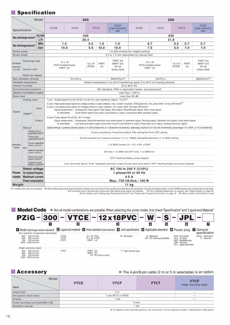
21 5 6 743
1 port : Analog signal (4 to 20 mA DC, 0 to 20 mA, input resistance: approx. 110 )*3
2 ports: High-speed pulse signal (no-voltage contact or open collector, max. number of pulses: 7500 pulse/min, min. pulse width: 4 msec (ON time))*3
2 ports: Low-speed pulse signal (no-voltage contact or open collector, min. pulse width: 50 msec (ON time))
Signal assignments : Unassigned, Pulse signal, Stop signal, Start signal, Reset/Restart signal, Alarm reset signal,
(4 selectable) Level Switch signal (only when Level Switch is used), Compulsive MAX operation signal
2 ports: Pulse signal (10 mA DC, 25 V or less)
Signal assignments : Unassigned, Solenoid-operation sync pulse signal, In-operation signal, Running signal, Operation end signal, Lamp alarm signal,
(4 selectable) Low tank-level alarm signal (only when 2-point Level Switch is used), Pulse-Input error signal, Analog-Input error signal
Digital settings: 3 patterns [stroke speed (1 to 300 strokes/min, in 1 stroke/min increments), discharge volume (in 0.1 mL/min increments), percentage (1 to 100%, in 1% increments)]
3000mPa.s*2
53031.8
0.77.0
0.77.0
34020.4
0.55.0
1.010.0
1.010.0
1.010.0
300 500
VTCE VTCF FTCT VTCE VTCF FTCT
12 x 18(PVC braided hose)
FNPT 1/2
12 x 15(PTFE)
FNPT1/2
0.55.0
0.77.0
12 x 15(PTFE)
FNPT1/2
FNPT 3/4MNPT 3/4
VP 20(Union Joint)
12 x 18(PVC braided hose)
FNPT 1/2
FNPT 3/4MNPT 3/4
VP 20(Union Joint)
12 x 18(PVC braided hose)
FNPT 1/2
12 x 15(PTFE)
FNPT 1/2
FNPT 3/4MNPT 3/4
VP 20(Union Joint)
( )VTCF
high-viscositytype ( )
VTCFhigh-viscosity
type
VTCF(High-viscosity type)
Specification
Power plug Generalspecification[for injection of general chemicals]
[High-viscosity type]
EUP : Euro plug*ULP : UL plugAUP : Australia plugUKP : UK plug*JPL : Japan lead wire
300 : 300 mL/min500 : 500 mL/min700 : 700 mL/min
1000 : 1000 mL/min
300 : 300 mL/min500 : 500 mL/min700 : 700 mL/min
1000 : 1000 mL/min
VTCEVTCFFTCT
VTCF
12 x 18 PVC12 x 15 PTFE
FNPT 1/2
FNPT 3/4MNPT 3/4
VP 20 (Union Joint)
W : Standard
V : high-viscosity type
S : StandardCE : CE marking-compatible
None : StandardX : Special
FTCTVTCFVTCE
3 m
1 set (R1/2 or R3/8)
1 set
Stroke speed
Stroke length
Max. allowable viscosity
Allowable temperature
Ambient humidity
Environmental protection
Altitude of instrallation location
Noise level
SignalDigital*4
PZ
iG
Input
Output
Specif ication
Model
mL/minL/hMPabar
Max. discharge volume*1
Max. discharge pressure*1
Connection(hose/tube:I.D x O.D)
Discharge side
Suction side
Relief /air-release
Manual
Analog-Input
Analog-Inputproportional control*5
Pulse-Inputproportional control*5
Count operation(batch control)
Interval operation(timer control)
External stopinput control
2-point LevelSwitch control*6
Operationmode
Rated voltageNo. of phases/FrequencyMaximum currentPower consumption
Powersupply
Weight
Auto
Control possible by Proportional Band (PB) setting/Set Point (SP) setting
Control possible by Frequency-division (1/1 to 1/9999) setting/Multiplication (1 to 9999) setting
1 to 9999 strokes (x1, x10, x100, x1000)
ON time: 1 to 9999 min/OFF time: 1 to 9999 min
"STP" flashing display, pump stopped
[Low tank-level alarm] "E-02" displayed and alarm output / [Lower tank-level alarm] "STP" flashing display and pump stopped
AC 100 to 240 V ( 10%)1-phase/50 or 60 Hz
4.0 AMax.: 750 VA/Ave.: 100 W
11 kg
1 to 300 strokes/min (digital setting)
0.3 to 1.5 mm (adjustable by manual dial)
50mPa.s
3000 mPa.s*250 mPa.s3000 mPa.s*250 mPa.s
Ambient temperature: 0 to 40 /Transferring liquid: 0 to 40 (no freezing allowed)
35 to 85% RH
IEC standard: IP65 or equivalent (water- and dust-proof)
Less than 1,000 m
Less than 85 dB
*1 Conditions: Clean water, room temperature *2 When transferring high-viscosity liquids, the maximum discharge volume may be lower than the specified volume depending on the characteristics of the liquid and operating conditions. Consult TACMINA separately when transferring high-viscosity liquids.
*3 Combined use of Analog-Input signal and high-speed pulse signal not possible. *4 For a detailed explanation on signals, see "Digital Signal" on page 26.
*5 For details, see "Analog-Input Proportional Control" and "Pulse-Input Proportional Control" on page 18. *6 When 2-point Level Switch is used
Model Code Not all model combinations are possible. When selecting the pump model, f irst check "Specif ication" and "Liquid-end Material".
PZiG 300 VTCE 12x18PVC W S JPL
Model (discharge volume standard)1 Joint specification4 Applicable standard5 6Hose standard (size/material)3Liquid-end material2 7
Accessory
Hose/ Tube*
Anti-siphon check valve
Strainer
Pump mounting nuts / bolts(M5 x 30)
Operation manual
Item
Model
4 sets
1 set
* For details on the hose/tube aperture, see "Connection" for the respective model in "Specification" table above.
The 4-pin/8-pin cable (2 m or 5 m selectable) is an option.
2019
170
14
339
165
150
1009
145
169338169
A170B38 32
170
14
D
165
150
1009
145
BA
C
EF170
38 32
170
14
C
165
150
R4.5 R4
.5
R4.510
09
145
AA
B
DE170
38 32
FTCT
1 port : Analog signal (4 to 20 mA DC, 0 to 20 mA, input resistance: approx. 110 )*3
2 ports: High-speed pulse signal (no-voltage contact or open collector, max. number of pulses: 7500 pulse/min, min. pulse width: 4 msec (ON time))*3
2 ports: Low-speed pulse signal (no-voltage contact or open collector, min. pulse width: 50 msec (ON time))
Signal assignments : Unassigned, Pulse signal, Stop signal, Start signal, Reset/Restart signal, Alarm reset signal,
(4 selectable) Level Switch signal (only when Level Switch is used), Compulsive MAX operation signal
2 ports: Pulse signal (10 mA DC, 25 V or less)
Signal assignments : Unassigned, Solenoid-operation sync pulse signal, In-operation signal, Running signal, Operation end signal, Lamp alarm signal,
(2 selectable) Low tank-level alarm signal (only when 2-point Level Switch is used), Pulse-Input error signal, Analog-Input error signal
Digital settings: 3 patterns [stroke speed (1 to 300 strokes/min, in 1 stroke/min increments), discharge volume (in 0.1 mL/min increments), percentage (1 to 100%, in 1% increments)]
Control possible by Proportional Band (PB) setting/Set Point (SP) setting
Control possible by Frequency-division (1/1 to 1/9999) setting/Multiplication (1 to 9999) setting
1 to 9999 strokes (x1, x10, x100, x1000)
ON time: 1 to 9999 min/OFF time: 1 to 9999 min
"STP" flashing display, pump stopped
[Low tank-level alarm] "E-02" displayed and alarm output / [Lower tank-level alarm] "STP" flashing display and pump stopped
12 x 18(PVC braided hose)
FNPT 1/2
12 x 15(PTFE)
FNPT 1/2
FNPT 3/4MNPT 3/4
VP 20(Union Joint)
VTCF(high-viscosity type)
( )VTCF
high-viscositytype( )
VTCFhigh-viscosity
type
Specification
100060.00.33.0
1000
VTCE VTCF FTCTVTCE VTCF
Pump head
Diaphragm
Check ball
O-rings
Valve seat
Joint
Ball stopper
Ball guide
Compressed coil spring
VTCE VTCF FTCT
PVC
PVC
PVC
PVC
Fluoro-rubber
Special fluoro-rubber
PVC
PVC
SUS304
Fluoro-rubber
Special fluoro-rubber
EPDM
EPDM
PVDF
PTFE
PTFE
PVDF
PTFE(valve stopper)
PTFE
Ceramic
VTCE/VTCF VTCF (high-viscosity type)FTCT
112103105
224206210
282273275
49.553.553.5
246253253
300/5007001000
A B C D E115128
97128
212256
285298
49.553.5
246253
300/500/7001000
A B C D E F249253
49.553.5
300/500/7001000
A B
Specif ication
Model
Stroke speed
Stroke length
Max. allowable viscosity
Allowable temperature
Ambient humidity
Environmental protection
Altitude of instrallation location
Noise level
mL/minL/hMPabar
Max. discharge volume*1
Max. discharge pressure*1
Discharge side
Suction side
Relief /air-release
SignalDigital*4
Input
Output
Connection(hose/tube:I.D x O.D)
Manual
Analog-Input
Analog-Inputproportional control*5
Pulse-Inputproportional control*5
Count operation(batch control)
Interval operation(timer control)
External stopinput control
2-point LevelSwitch control
Operationmode
Rated voltageNo. of phases/FrequencyMaximum currentPower consumption
Powersupply
Weight
Auto
AC 100 to 240 V ( 10%)1-phase/50 or 60 Hz
4.0 AMax.: 750 VA/Ave.: 100 W
11 kg
1 to 300 strokes/min (digital setting)
0.3 to 1.5 mm (adjustable by manual dial)
3000 mPa.s*250 mPa.s
Ambient temperature: 0 to 40 /Transferring liquid: 0 to 40 (no freezing allowed)
35 to 85% RH
IEC standard: IP65 or equivalent (water- and dust-proof)
Less than 1,000 m
Less than 85 dB
*1 Conditions: Clean water, room temperature *2 When transferring high-viscosity liquids, the maximum discharge volume may be lower than the specified volume depending on the characteristics of the liquid and operating conditions. Consult TACMINA separately when transferring high-viscosity liquids.
*3 Combined use of Analog-Input signal and high-speed pulse signal not possible. *4 For a detailed explanation on signals, see "Digital Signals" on page 26.
*5 For details, see "Analog-Input Proportional Control" and "Pulse-Input Proportional Control" on page 18. *6 When 2-point Level Switch is used
Also refer to the "Corrosion-resistance Table" on page 26.Liquid-end Material
External Dimension (mm)
Part Model
*6
Model Model Model
76045.60.44.0
700
TM_00146571_P19_P20_1407_1_1C M Y K
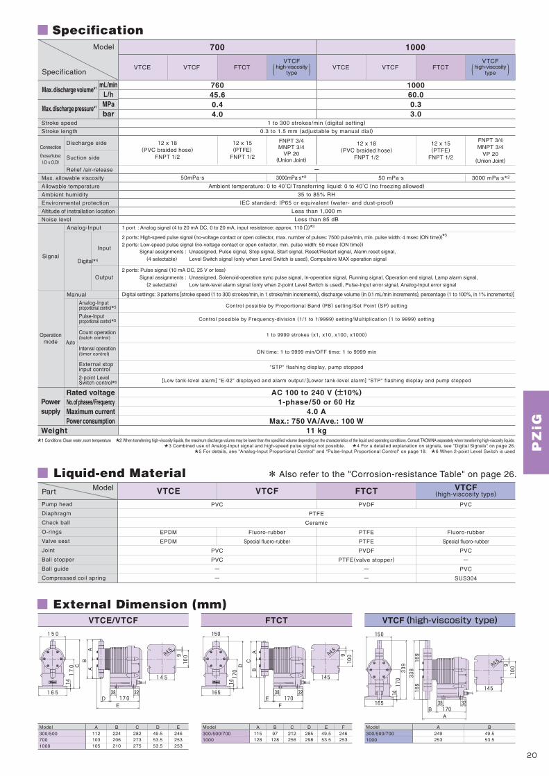

For S
odiu
mH
ypoc
hlor
ite
CLPWCLPWM
CLPWT
DCLPWDCLPWM
DCLPWT
Digital-input/outputDigital-input/output &Analog-inputDigital-input/output &Timer Control
Digital-input/outputDigital-input/output &Analog-inputDigital-input/output &Timer Control
CLPZ No-input
DCLPWAir Block
In-Line Automatic Air-release
In-Line Automatic Air-releaseCLPW CLPZ
■Model code
■External dimensions
■Liquid-end materials ■Accessories
1 2 3 74 65
30 ATCF 4×9PVC S8
JPLWDCLPW
■Specifications
●DCLPW/DCLPWM/DCLPWT ●CLPW/CLPWM/CLPWT ●CLPZ
ECO
SAFESAFESAFE
PL
STOP
Manual1/n×n
strokes/minmL/minCAL
Air purge port(3/8"OD×1/4"ID)Air release
Air purge port(φ4×φ6)Air release
NEPO
118(154)
20 757
185.8
(216)
76109.8
140
87
87
R3
6
118
86 77
(178)
30.2
32.8
ECO
SAFESAFESAFE
PL
STOP
Manual1/n×n
strokes/minmL/minCAL
Air purge portAir release
NEPO
118(150.5)
16.5 75
(147)
74 7
34
152
(216)
7676
140
87
87
R3
6
118
*1 Conditions:Clean water, room temperature.*2 0.7MPa (7bar) for models w/relief valve(R type) whereas 1.0MPa (10bar) for models w/o relief valve.*3 Provided for the DCLPW series only.
*For details on the control functions, see "Control function specifications" on page 12.
Control type2 Model (discharge volume standard)
3 Liquid-end material4 Hose standard (size/material)
5 Joint specification6 Applicable standard7 Power plug8
DCLPW CLPW CLPZ
1m
3m
Item
Hose/tube
Air purge hose with relief valve*1
Degassing joint
Anti siphonal check valve
Foot valve
1 set (hose already attached)
---
2m
---
1 set
------PVC
1 set (R1/2)
1piece
Signal cable
Pump attachment bolts and nuts
Operating instructions
1 set
1 copy
Cable ties (INSULOK®) for relief hose (spare)*2
Acrylic(PMMA)PTFE
Ceramic
Fluoro rubber
Special fluoro rubber
PTFE
PVC
PVC
Item
Pump head
Diaphragm
Check ball
O-ring
Valve seat
Packing
Joint
Degassing joint
Ball stopper
SpecificationModel
Max.dischargevolume
Max.dischargepressure
Connection(hose/tube:I.D × O.D)
Weight
Stroke speed Stroke length
Viscosity of transfer liquidTemperature of transfer liquid
Ambient temperatureEnvironmental resistance
mL/minL/HMPabar
Discharge side
Suction side
Air-releaseDegassing joint*3
kg
*1 The air purge hose with relief valve is already attached to this pump.*2 This accessory is supplied for models with the relief valve (R type).* The signal cable is sold separately. The signal cable is included when the □PWM and the chemical injection PTS series are purchased as a set.
Series name1
DCLPW
1/4" × 3/8" (soft PVC hose)
1 to 300 strokes/min (Enables setting in 1-stroke units)0.5~1 mm (Enables adjustment using the dial)
15 to 300 strokes/min (dial setting)Fixed at 1.0 mm
30R301.8
2 2.1 2 2.1 1.8 1.9 1.8 1.9 1.7 1.8 1.7 1.8
0.77.0
4 × 6 (soft PVC hose) 4 × 6 (soft PVC hose)--
- 4 × 6 (soft PVC hose) -
4 × 9(PVC braided hose)
6 × 8(PE)
1/4" × 3/8"(PE)
6 × 11(PVC braided hose)
6 × 8(PE)
1/4" × 3/8"(PE)
4 × 9(PVC braided hose)
6 × 8(PE)
1/4" × 3/8"(PE)
6 × 11(PVC braided hose)
6 × 8(PE)
1/4" × 3/8"(PE)
4 × 9(PVC braided hose)
6 × 8(PE)
1/4" × 3/8"(PE)
6 × 11(PVC braided hose)
6 × 8(PE)
1/4" × 3/8"(PE)
4 × 9(PVC braided hose)
6 × 8(PE)
1/4" × 3/8"(PE)
6 × 11(PVC braided hose)
6 × 8(PE)
1/4" × 3/8"(PE)
4 × 9(PVC braided hose)
6 × 8(PE)
1/4" × 3/8"(PE)
6 × 11(PVC braided hose)
6 × 8(PE)
1/4" × 3/8"(PE)
4 × 9(PVC braided hose)
6 × 8(PE)
1/4" × 3/8"(PE)
6 × 11(PVC braided hose)
6 × 8(PE)
1/4" × 3/8"(PE)
0.77.0
0.77.0
0.77.0
0.77.0
0.44.0
0.44.0
0.88.0
1.010.0
1.010.0
1.010.0
603.6
905.4
301.8
603.6
905.4
301.8
603.6
905.4
301.8
603.6
905.4
301.8
603.6
1006
301.8
603.6
1006
60R 100R 30 60 100 30R 60R 100R 30 60 100 30R 60R 100R 30 60 100CLPW
50mPa・s or less0~40℃(no freezing allowed)
0~40℃IEC standard:IP65 or equivalent (water-&dust-proof)
CLPZ
DCLPW CLPW CLPZ
*Not all model combinations are possible. When selecting the pump model, first check “Specification” and “Liguid-end material”.
*Power cable(2m)is attached.
ATCF 4×9PVC6×11PVC6×8PE1/4"×3/8"PE
S: StandardCE: CE marking -compatible
W: Standard
[W/ relief valve] 30R: 30mL/min 60R: 60mL/min 100R: 90mL/min
[W/O relief valve] 30 : 30mL/min 60 : 60mL/min 100 : 90mL/min
EUP:Euro plugULP :UL plugAUP:Australia plugUKP:UK plugJPL:Japan lead wire
DCLPW : Air block and in-line type automatic air- release functions CLPW : In-line type automatic air-release function
None : Standard (pulse input) type M : Analog input type T : Timer control type
ATCF 4×9PVC6×11PVC6×8PE1/4"×3/8"PE
S: StandardCE: CE marking -compatible
W: Standard
[W/ relief valve] 30R: 30mL/min
[W/O relief valve] 30 : 50mL/min
EUP:Euro plugULP :UL plugAUP:Australia plugUKP:UK plugJPL:Japan lead wire
CLPZ None : No-input
●Conventional design ●New design
For details, see “Higher Safety”on page 7.
[DCL/CL series][Conventional pumps]
Main pipe (raw water)
Main pipe (raw water)
Crystallization caused by reaction between sodium hypochlorite and calcium in raw water.
The check valve cap closes to prevent crystallization caused by reaction between sodium hypochlorite and calcium in raw water.
Injection point (no injection state)
■Easy-to-check trapped air
■Anti siphonal check valve that prevents clogging at the injection point ■Alarm function for notifying injection trouble
■In-line type automatic air-release mechanism
■Air-release performance
■Air block mechanism
Two mechanisms for preventing gas lock
Prevention of trouble caused by crystallization
The transparent acrylic pump head, which has an innovative design to minimize dead space, enables the operator to check the trapped air at a glance.
Air
Suction
Liquid
Standby state
The pressure inside the discharge side and pump head becomes equal and the air is compressed.
Air is discharged from a dedicated air purge port. Chemical liquid leaks into the air purge port side under some conditions and the discharge volume becomes unstable.
Discharge process
The smaller volume of air after it is compressed is discharged together with the liquid.
DCL and CL series are equipped with an air-release mechanism designed using a new concept.The in-line air-release mechanism of these models assures the elimination of air that is trapped in the pump head and automatically prevents the discharge trouble caused by gas lock.
Comparison of the time required to purge air that is trapped in the pump head between CLPW and previous models (CLPZD, ARPZD).
When injection trouble occurs, an alarm is emitted to warn this condition.
DCL series pumps are equipped with a degassing joint as standard equipment. The degassing joint prevents intrusion of air that causes gas lock.
Air
Chemicalliquid
Chemical liquid and air
Air purge tim
e [sec.]
Air purge tim
e [sec.]
Prevents intrusion of maximum 15cc of air.
Previous modelCL type
Previous modelAR type
Previous modelCL type
Previous modelAR type
120
100
80
60
40
20
0
Approx. 66%reduction
Approx. 60%reduction
Unable to purge air
600
500
400
300
200
100
0
Test conditions (Discharge pressure: 1.0MPa, air volume: 0.1mL) Test conditions (Discharge pressure: 1.0MPa, air volume: 0.5mL)
87
R3 6
( 206
)
(120)
118
130
8
(150.5)
110
152
76
16.5
76
70
DCLP
W/CL
PW/CL
PZ
2221
[ Usage Precaution ]When diluting sodium hypochlorite, use pure water or water processed with a water softener. Otherwise the pump may malfunction or discharge trouble may result.
TM_00146571_P21_P22_1407_1_1C M Y K
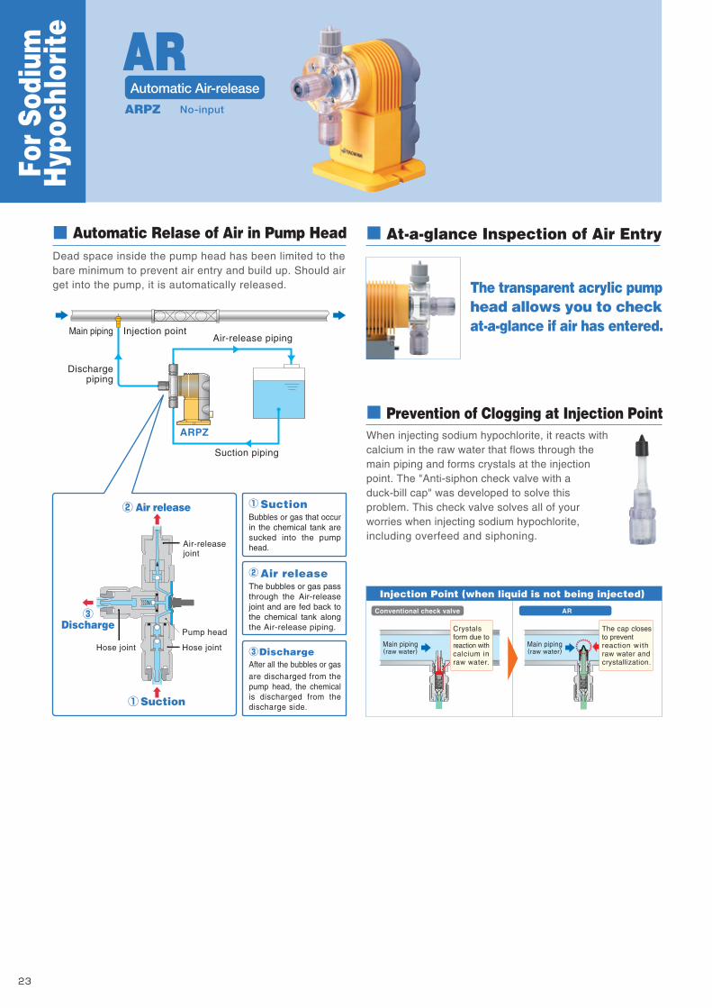
For S
odiu
mH
ypoc
hlor
ite
No-inputARPZ
The transparent acrylic pumphead allows you to checkat-a-glance if air has entered.
At-a-glance Inspection of Air Entry
Air-release piping
Suction piping
Injection point
Dischargepiping
ARPZ
Air releaseThe bubbles or gas pass through the Air-release joint and are fed back to the chemical tank along the Air-release piping.
SuctionBubbles or gas that occur in the chemical tank are sucked into the pump head.
DischargeAfter all the bubbles or gas are discharged from the pump head, the chemical is discharged from the discharge side.
Discharge
Suction
Air release
Air-releasejoint
Hose joint Hose joint
Pump head
Automatic Relase of Air in Pump HeadDead space inside the pump head has been limited to thebare minimum to prevent air entry and build up. Should airget into the pump, it is automatically released.
Main piping
The cap closesto preventreaction wi thraw water andcrystallization.
Main piping(raw water)
Main piping(raw water)
Crystalsform due toreaction withcalcium inraw water.
Injection Point (when liquid is not being injected)
Prevention of Clogging at Injection PointWhen injecting sodium hypochlorite, it reacts with calcium in the raw water that flows through the main piping and forms crystals at the injection point. The "Anti-siphon check valve with a duck-bill cap" was developed to solve this problem. This check valve solves all of your worries when injecting sodium hypochlorite, including overfeed and siphoning.
Conventional check valve AR
R3 6
130
118
83
8
( 202
)(57)
(190)
70110
7614
872
87
21 5 6 743
mL/minL/hMPabar
Max. discharge volume*
Max. discharge pressure*
Stroke speed
Stroke length
Max. allowable viscosity
Allowable temperature
Ambient humidity
Environmental protection
Altitude of instrallation location
Noise level
Connection(hose/tube:I.D x O.D)
Discharge side
Suction side
Air-release
Rated voltageNo. of phases/FrequencyMaximum current
Powersupply
Weight
The operation modes of the ARPZ is the same as those for the PZ, respectively.Specification
Specif ication
Model
271.621.0
10.0
935.580.44.0
31 12
All Models All Models
ARPZ
6 x 11(PVC braided hose)
6 x 8(PE)
1/4" x 3/8"(PE)
4 x 9(PVC braided hose)
6 x 8(PE)
1/4" x 3/8"(PE)
4 x 8 (soft PVC hose)
50 mPa.s
Ambient temperature: 0 to 40 /Transferring liquid: 0 to 40 (no freezing allowed)
35 to 85% RH
IEC standard: IP65 or equivalent (water- and dust-proof)
Less than 1,000 m
Less than 85 dB
AC 100 to 240 V ( 10%)1-phase/50 or 60 Hz
2.5 A250 VA18 W
1.8 kg
2.0 A 200 VA
15 W1.7 kg
* Conditions: Clean water, room temperature
* Power cable(2m)is attachedLiquid End Material Accessory
Part
Pump head
Diaphragm
Check ball
O-ring
Valve seat
Joint
Ball stopper
Compressed coil spring
Acrylic (PMMA)
PTFE
Ceramic
Fluoro-rubber
Special fluoro-rubber
PVC
PVC
Hastelloy C
Model
Hose/ Tube*1
Air-release hose*1
Anti-siphon check valve
Foot valve
Ceramic weight
Pump mounting nuts / bolts
Operation manual
ItemModel
3 m
1 m
1 set (R1/2)
1 set
1 set*2
2 sets (M5 x 30)
1 set
Model Code
External Dimension (mm)
The mounting pitch allows mounting from 87 to 110 mm.
ARPZ 31 CL 4x9PVC W S JPL
Powerconsumption
Max.Ave.
Also refer to the "Corrosion-resistance Table" on page 26.
EUP : Euro plugULP : UL plugAUP : Australia plugUKP : UK plugJPL : Japan lead wire
31 : 30 mL/min 61 : 60 mL/min 12 : 100 mL/min
ARPZ : Manual setting, No-Input CL 4 x 9 PVC6 x 11 PVC6 x 8 PE
1/4" x 3/8" PE
W : Standard
S : StandardCE : CE marking-compatible
Model (discharge volume standard)2 Joint specification5
Applicable standard6
Hose standard (size/material)4Liquid-end material3Series name1 Power plug7
*1 For details on the hose/tube aperture, see "Connection" for the respective model in "Specification" table above.
*2 Only when PE tube is selected
Not all model combinations are possible. When selecting the pump model, f irst check "Specification" and "Liquid-end Material".
543.240.88.0
ARPZ
61
Fixed at 1.0 mm
15 to 300 strokes/min (dial setting)
2423
ARAutomatic Air-release
AR
TM_00146571_P23_P24_1407_1_1C M Y K

For S
odiu
mH
ypoc
hlor
ite
No-inputARPZ
The transparent acrylic pumphead allows you to checkat-a-glance if air has entered.
At-a-glance Inspection of Air Entry
Air-release piping
Suction piping
Injection point
Dischargepiping
ARPZ
Air releaseThe bubbles or gas pass through the Air-release joint and are fed back to the chemical tank along the Air-release piping.
SuctionBubbles or gas that occur in the chemical tank are sucked into the pump head.
DischargeAfter all the bubbles or gas are discharged from the pump head, the chemical is discharged from the discharge side.
Discharge
Suction
Air release
Air-releasejoint
Hose joint Hose joint
Pump head
Automatic Relase of Air in Pump HeadDead space inside the pump head has been limited to thebare minimum to prevent air entry and build up. Should airget into the pump, it is automatically released.
Main piping
The cap closesto preventreaction wi thraw water andcrystallization.
Main piping(raw water)
Main piping(raw water)
Crystalsform due toreaction withcalcium inraw water.
Injection Point (when liquid is not being injected)
Prevention of Clogging at Injection PointWhen injecting sodium hypochlorite, it reacts with calcium in the raw water that flows through the main piping and forms crystals at the injection point. The "Anti-siphon check valve with a duck-bill cap" was developed to solve this problem. This check valve solves all of your worries when injecting sodium hypochlorite, including overfeed and siphoning.
Conventional check valve AR
R3 6
130
118
83
8
( 202
)
(57)
(190)
70110
7614
872
87
21 5 6 743
mL/minL/hMPabar
Max. discharge volume*
Max. discharge pressure*
Stroke speed
Stroke length
Max. allowable viscosity
Allowable temperature
Ambient humidity
Environmental protection
Altitude of instrallation location
Noise level
Connection(hose/tube:I.D x O.D)
Discharge side
Suction side
Air-release
Rated voltageNo. of phases/FrequencyMaximum current
Powersupply
Weight
The operation modes of the ARPZ is the same as those for the PZ, respectively.Specification
Specif ication
Model
271.621.0
10.0
935.580.44.0
31 12
All Models All Models
ARPZ
6 x 11(PVC braided hose)
6 x 8(PE)
1/4" x 3/8"(PE)
4 x 9(PVC braided hose)
6 x 8(PE)
1/4" x 3/8"(PE)
4 x 8 (soft PVC hose)
50 mPa.s
Ambient temperature: 0 to 40 /Transferring liquid: 0 to 40 (no freezing allowed)
35 to 85% RH
IEC standard: IP65 or equivalent (water- and dust-proof)
Less than 1,000 m
Less than 85 dB
AC 100 to 240 V ( 10%)1-phase/50 or 60 Hz
2.5 A250 VA18 W
1.8 kg
2.0 A 200 VA
15 W1.7 kg
* Conditions: Clean water, room temperature
* Power cable(2m)is attachedLiquid End Material Accessory
Part
Pump head
Diaphragm
Check ball
O-ring
Valve seat
Joint
Ball stopper
Compressed coil spring
Acrylic (PMMA)
PTFE
Ceramic
Fluoro-rubber
Special fluoro-rubber
PVC
PVC
Hastelloy C
Model
Hose/ Tube*1
Air-release hose*1
Anti-siphon check valve
Foot valve
Ceramic weight
Pump mounting nuts / bolts
Operation manual
ItemModel
3 m
1 m
1 set (R1/2)
1 set
1 set*2
2 sets (M5 x 30)
1 set
Model Code
External Dimension (mm)
The mounting pitch allows mounting from 87 to 110 mm.
ARPZ 31 CL 4x9PVC W S JPL
Powerconsumption
Max.Ave.
Also refer to the "Corrosion-resistance Table" on page 26.
EUP : Euro plugULP : UL plugAUP : Australia plugUKP : UK plugJPL : Japan lead wire
31 : 30 mL/min 61 : 60 mL/min 12 : 100 mL/min
ARPZ : Manual setting, No-Input CL 4 x 9 PVC6 x 11 PVC6 x 8 PE
1/4" x 3/8" PE
W : Standard
S : StandardCE : CE marking-compatible
Model (discharge volume standard)2 Joint specification5
Applicable standard6
Hose standard (size/material)4Liquid-end material3Series name1 Power plug7
*1 For details on the hose/tube aperture, see "Connection" for the respective model in "Specification" table above.
*2 Only when PE tube is selected
Not all model combinations are possible. When selecting the pump model, f irst check "Specification" and "Liquid-end Material".
543.240.88.0
ARPZ
61
Fixed at 1.0 mm
15 to 300 strokes/min (dial setting)
2423
ARAutomatic Air-release
AR
TM_00146571_P23_P24_1407_1_1C M Y K
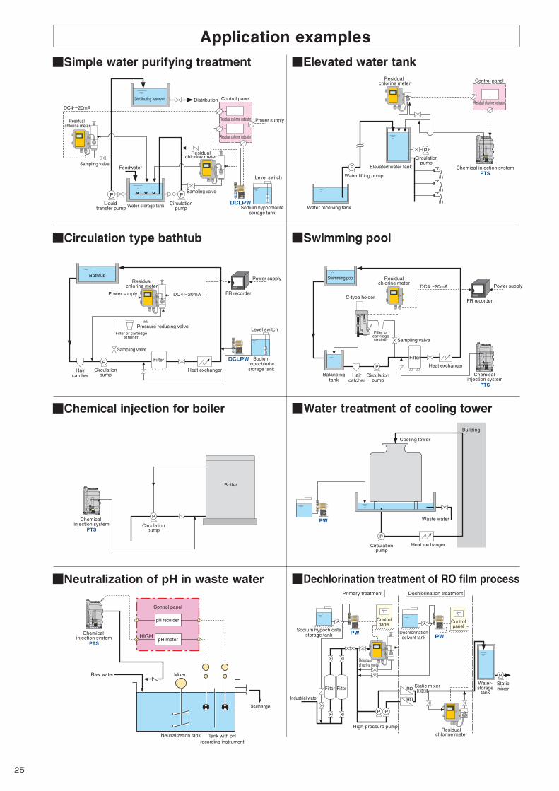
PW
DC4~20mA FR recorder
Heat exchangerHaircatcher
P
Filter or cartridgestrainer
Pressure reducing valve
Bathtub
Filter
Liquid transfer pump
Circulationpump Sodium hypochlorite
storage tank
Water-storage tank
FeedwaterSampling valve
Sampling valve
Level switch
Distribution
Power supply
Control panel
Residual chlorine indicator
Residual chlorine indicator
P
DC4~20mA
Residual chlorine meter
Residual chlorine meter
Residualchlorine meter
P
Distributing reservoir
Chemical injection systemPTS
Water receiving tank
Water lifting pump
P Elevated water tank
P
Primary treatment Dechlorination treatment
Sodium hypochloritestorage tank
High-pressure pump
Static mixer Staticmixer
PP
Industrial water
RO
RO
Dechlorinationsolvent tank
P
DC4~20mA
C-type holder
Balancingtank
P
Swimming pool
■Simple water purifying treatment ■Elevated water tank
■Circulation type bathtub
■Chemical injection for boiler
■Neutralization of pH in waste water
■Swimming pool
■Dechlorination treatment of RO film process
■Water treatment of cooling tower
Application examples
Boiler
P Waste water
Cooling tower
Building
P
DCLPW
DCLPW
Raw water
Discharge
Neutralization tank Tank with pHrecording instrument
Mixer
pH recorder
pH meter
ECO
SAFE
PL
STOP
Manual1/n×n
strokes/minmL/minCAL
PW
ECO
SAFE
PL
STOP
Manual1/n×n
strokes/minmL/minCAL
PW
ECO
SAFE
PL
STOP
Manual1/n×n
strokes/minmL/minCAL
ECO
SAFE
PL
STOP
Manual1/n×n
strokes/minmL/minCAL
ECO
SAFE
PL
STOP
Manual1/n×n
strokes/minmL/minCAL
Control panel
Residual chlorine indicator
Circulationpump
Chemical injection system
PTS
Residualchlorine meter
Residualchlorine meter
Sampling valve
Sampling valve
Circulationpump
Circulationpump
Circulationpump
Circulationpump
Power supply
FR recorder
Power supply
Power supply
Sodiumhypochloritestorage tank
Level switch
Haircatcher
Filter
Filter orcartridgestrainer
Heat exchanger
Heat exchanger
Chemical injection system
PTS
Control panel
Chemical injection system
PTS
Residualchlorine meter
Residualchlorine meter
Water-storage
tank
Controlpanel Control
panel
Filter Filter
Selected ports not to be unassigned
Input signal required for Pulse-Input proportional control
Signal from an external device to stop the pump
Signal from an external device to start the pump
Signal from an external device to reset the current value (count, time) during count operation (batch control) or
interval operation (timer control) and to restart operation
Signal from an external device to reset display/output of errors and alarms
Signal from the Level Switch installed in the tank to stop the pump operation
Signal that forces the pump to run at MAX speed (300 strokes/min) regardless of operation mode
Selected ports not to be unassigned
One pulse signal to be output per stroke
Signal to be output during the operation (including "in standby")
Signal to be output during the pump is running (not including "in standby")
Signal to be output when the preset number of strokes is reached during count operation (batch control)
Signal to be output when one of the following errors and alarms is detected
Signal to be output when 2-point Level Switch is used and the volume of the chemical has fallen to the preset (low) level (Low tank-level alarm)
Signal to be output when the number of Pulse-Input signals momentarily exceeds the buffer size during Pulse-Input proportional control
Signal to be output when the Analog-Input signal goes outside of the specified range during Analog -Input proportional control (In the case of the 4 to 20 mA range, 3 mA or less or 22 mA or more. In the case of the 0 to 20 mA range, 0 mA or less or 22 mA or more)
Unassigned
Pulse signal
Stop signal
Start signal
Reset/Restart signal
Alarm reset signal
Level Switch signal*1
Compulsive MAX operation signal
Unassigned
Solenoid-operationsync pulse signal
In-operation signal
Running signal
Operation end signal
Lamp a Alarm signal
Tank-level alarm signal*1
Pulse-Input error signal
Analog-Input error signal
Input
Output
Memory-read error
Tank-level alarm*1
Pulse-Input error
Analog-Input error
Error/Alarm
*1 When Flow Checker is used
*1 When Level Switch is used
* When transferring high-viscosity liquids, the maximum discharge volume may be lower than the specified volume depending on the characteristics of the liquid and operating conditions. Consult TACMINA separately when transferring high-viscosity liquids.
The corrosion resistance of materials is greatly affected by temperature, concentration, UV rays, and other environmental conditions. For this reason, this selection table does not completely guarantee safety.The above figures are the corrosion resistance for pump liquid-end materials. Consult TACMINA separately regarding the corrosion resistance of hoses and tubes.
to 60% to 60%
to 3000mPa.s*
to 20%
to 80%
to 20%
to 80%
to 12%
to 30%
to 38%
to 98%
to 12%
to 30%
to 12%
98%
to 90%
Corrosion-resistance Table
Hydrochloric acid
Sulfuric acid
Sodium hydroxide
Aqueous ammonia
Sodium hypochlorite
Hydrogen peroxide
Poly-aluminum chloride (PAC)
Aluminum sulfate
Polymer coagulants
VTCE VTCFChemical (0 to 40 )
Liquid-end materialATCFSTCTFTCE FTCF FTCT 6TCT
HC
H2SO4
NaOH
NH4OH
NaC O
H2O2
A 2 (SO4)3
( )
Also refer to "Liquid-end Material" for each model.
VTCETfor injection ofboiler chemicals
* PZ/PW only
VTCFhigh-viscosity
type
*PW/PZD/PZiG only( )
Pump circuit- or program-related error
Alarm when the chemical volume has fallen to the preset (low) level
Error when the number of Pulse-Input signals momentarily exceeds the buffer size during Pulse-Input proportional control
Error when the Analog-Input signal goes outside of the specified range during Analog -Input proportional control (In the case of the 4 to 20 mA range, 3 mA or less or 22 mA or more. In the case of the 0 to 20 mA range, 0 mA or less or 22 mA or more)
Error & Alarm Also refer to "By Function" on page 4.
Explanation
Digital Signal Also refer to "Specification" for each model.
When 2-point Level Switch is used ... [Low tank-level alarm] "E-02" displayed and alarm output/ [Lower tank-level alarm] "STP" flashing display and pump stopped
For Lower tank-level alarm, "STP" flashing display and pump stopped. However, no signal is output
2625
OT
HE
R
TM_00146571_P25_P26_1407_1_1C M Y K

PW
DC4~20mA FR recorder
Heat exchangerHaircatcher
P
Filter or cartridgestrainer
Pressure reducing valve
Bathtub
Filter
Liquid transfer pump
Circulationpump Sodium hypochlorite
storage tank
Water-storage tank
FeedwaterSampling valve
Sampling valve
Level switch
Distribution
Power supply
Control panel
Residual chlorine indicator
Residual chlorine indicator
P
DC4~20mA
Residual chlorine meter
Residual chlorine meter
Residualchlorine meter
P
Distributing reservoir
Chemical injection systemPTS
Water receiving tank
Water lifting pump
P Elevated water tank
P
Primary treatment Dechlorination treatment
Sodium hypochloritestorage tank
High-pressure pump
Static mixer Staticmixer
PP
Industrial water
RO
RO
Dechlorinationsolvent tank
P
DC4~20mA
C-type holder
Balancingtank
P
Swimming pool
■Simple water purifying treatment ■Elevated water tank
■Circulation type bathtub
■Chemical injection for boiler
■Neutralization of pH in waste water
■Swimming pool
■Dechlorination treatment of RO film process
■Water treatment of cooling tower
Application examples
Boiler
P Waste water
Cooling tower
Building
P
DCLPW
DCLPW
Raw water
Discharge
Neutralization tank Tank with pHrecording instrument
Mixer
pH recorder
pH meter
ECO
SAFE
PL
STOP
Manual1/n×n
strokes/minmL/minCAL
PW
ECO
SAFE
PL
STOP
Manual1/n×n
strokes/minmL/minCAL
PW
ECO
SAFE
PL
STOP
Manual1/n×n
strokes/minmL/minCAL
ECO
SAFE
PL
STOP
Manual1/n×n
strokes/minmL/minCAL
ECO
SAFE
PL
STOP
Manual1/n×n
strokes/minmL/minCAL
Control panel
Residual chlorine indicator
Circulationpump
Chemical injection system
PTS
Residualchlorine meter
Residualchlorine meter
Sampling valve
Sampling valve
Circulationpump
Circulationpump
Circulationpump
Circulationpump
Power supply
FR recorder
Power supply
Power supply
Sodiumhypochloritestorage tank
Level switch
Haircatcher
Filter
Filter orcartridgestrainer
Heat exchanger
Heat exchanger
Chemical injection system
PTS
Control panel
Chemical injection system
PTS
Residualchlorine meter
Residualchlorine meter
Water-storage
tank
Controlpanel Control
panel
Filter Filter
Selected ports not to be unassigned
Input signal required for Pulse-Input proportional control
Signal from an external device to stop the pump
Signal from an external device to start the pump
Signal from an external device to reset the current value (count, time) during count operation (batch control) or
interval operation (timer control) and to restart operation
Signal from an external device to reset display/output of errors and alarms
Signal from the Level Switch installed in the tank to stop the pump operation
Signal that forces the pump to run at MAX speed (300 strokes/min) regardless of operation mode
Selected ports not to be unassigned
One pulse signal to be output per stroke
Signal to be output during the operation (including "in standby")
Signal to be output during the pump is running (not including "in standby")
Signal to be output when the preset number of strokes is reached during count operation (batch control)
Signal to be output when one of the following errors and alarms is detected
Signal to be output when 2-point Level Switch is used and the volume of the chemical has fallen to the preset (low) level (Low tank-level alarm)
Signal to be output when the number of Pulse-Input signals momentarily exceeds the buffer size during Pulse-Input proportional control
Signal to be output when the Analog-Input signal goes outside of the specified range during Analog -Input proportional control (In the case of the 4 to 20 mA range, 3 mA or less or 22 mA or more. In the case of the 0 to 20 mA range, 0 mA or less or 22 mA or more)
Unassigned
Pulse signal
Stop signal
Start signal
Reset/Restart signal
Alarm reset signal
Level Switch signal*1
Compulsive MAX operation signal
Unassigned
Solenoid-operationsync pulse signal
In-operation signal
Running signal
Operation end signal
Lamp a Alarm signal
Tank-level alarm signal*1
Pulse-Input error signal
Analog-Input error signal
Input
Output
Memory-read error
Tank-level alarm*1
Pulse-Input error
Analog-Input error
Error/Alarm
*1 When Flow Checker is used
*1 When Level Switch is used
* When transferring high-viscosity liquids, the maximum discharge volume may be lower than the specified volume depending on the characteristics of the liquid and operating conditions. Consult TACMINA separately when transferring high-viscosity liquids.
The corrosion resistance of materials is greatly affected by temperature, concentration, UV rays, and other environmental conditions. For this reason, this selection table does not completely guarantee safety.The above figures are the corrosion resistance for pump liquid-end materials. Consult TACMINA separately regarding the corrosion resistance of hoses and tubes.
to 60% to 60%
to 3000mPa.s*
to 20%
to 80%
to 20%
to 80%
to 12%
to 30%
to 38%
to 98%
to 12%
to 30%
to 12%
98%
to 90%
Corrosion-resistance Table
Hydrochloric acid
Sulfuric acid
Sodium hydroxide
Aqueous ammonia
Sodium hypochlorite
Hydrogen peroxide
Poly-aluminum chloride (PAC)
Aluminum sulfate
Polymer coagulants
VTCE VTCFChemical (0 to 40 )
Liquid-end materialATCFSTCTFTCE FTCF FTCT 6TCT
HC
H2SO4
NaOH
NH4OH
NaC O
H2O2
A 2 (SO4)3
( )
Also refer to "Liquid-end Material" for each model.
VTCETfor injection ofboiler chemicals
* PZ/PW only
VTCFhigh-viscosity
type
*PW/PZD/PZiG only( )
Pump circuit- or program-related error
Alarm when the chemical volume has fallen to the preset (low) level
Error when the number of Pulse-Input signals momentarily exceeds the buffer size during Pulse-Input proportional control
Error when the Analog-Input signal goes outside of the specified range during Analog -Input proportional control (In the case of the 4 to 20 mA range, 3 mA or less or 22 mA or more. In the case of the 0 to 20 mA range, 0 mA or less or 22 mA or more)
Error & Alarm Also refer to "By Function" on page 4.
Explanation
Digital Signal Also refer to "Specification" for each model.
When 2-point Level Switch is used ... [Low tank-level alarm] "E-02" displayed and alarm output/ [Lower tank-level alarm] "STP" flashing display and pump stopped
For Lower tank-level alarm, "STP" flashing display and pump stopped. However, no signal is output
2625
OT
HE
R
TM_00146571_P25_P26_1407_1_1C M Y K

www.tacmina.com
Solenoid-drivenDiaphragm Metering Pump
EC-054 (5) 052014/7/ASSHead Office:
2-2-14 Awajimachi, Chuo-ku, Osaka 541-0047 JapanTel.+81(0)6-6208-3974 Fax.+81(0)6-6208-3978URL http://www.tacmina.comE-mail [email protected]
Product designs and specifications are subject to change without notice for product improvement.
■ Related equipments
25 to 1000LTank capacity
Relief valve automatically releases excessive pressure that builds up inside the discharge side pipes due to clogging of the pipes or while the discharge valve is closed. It can prevent accidents such as damage to the pump or piping.
● Relief valve (safety valve)
● Flow checkerFlow checker is highly resistant to acid and alkalis and allows the injection operation of the pump to be checked at low cost. The pump-direct connection type and hose connection type are the two types of volume checkers available.
Degassing joint is installed at the suction side of a pump. It separates absorbed air bubbles from the liquid to prevent air bubbles from entering the pump head.
This joint is supplied with the DCLPW series as standard equipment.
*
● Degassing joint
Back pressure valve prevents excessive liquid flow and siphon effect by sealing the outlet port of the liquid with a diaphragm, and by applying just enough force (back pressure) to overcome the fluid inertia force.
● Parts kitParts kit includes all required consumables in a set and is more economical than purchasing the parts separately. Since all consumables are packaged in one box, it also makes inventory management easier.
● Back pressure valve
These optional products enable you to check the injection operation visually as well as by means of a sensor.
● Flow indicator and photoelectric sensorFloat switch will stop the pump when the remaining volume of chemical liquid in the tank becomes low. They also cause an alarm to be emitted to notify you that it is time to refill the liquid. Two types of float switches are available, namely the float type with choices of one-point and two-point type sensors, and the electrode type, which is highly resistant to chemicals.
● Float switch
Solution tank PE tank PVC tank
Tank
■ Options
● Residual pressure exhaustion valveResidual pressure exhaustion valve is directly connected to the discharge side of the pump so that the pipes can be safely purged of abnormal pressure that builds up. It also enables residual pressure and residual liquid to be safely discharged when maintenance services are performed.
● Pulse generator type flowmeterWhen using this flowmeter in combination with a Tacmina pulse signal input type metering pump, you can construct a simple and low-cost injection system proportional to the required flow rate.
PTSChemical injection system
30/50/120 LTank capacity
Pump and tank combination
●Compact design and easy to assemble in equipment and install.●You can start operation by simply connecting the power supply and piping.
TM_00146571_H01_H04_1407_1_1C M Y K


