
November, 2011Greg Ashley
Solar Frontier CIS module

Solar Frontier CIS| November 2011 | Greg Ashley
About Solar Frontier
100% subsidiary of Showa Shell Sekiyu, with 110 years experience in energy30+ years experience in solar1,000+ employeesOffices in Tokyo, Munich, Santa Clara2010 80 MW production rising to 980 MW from 2011
© Solar Frontier K.K.

Solar Frontier CIS| November 2011 | Greg Ashley
Solar Frontier History
2© Solar Frontier K.K.
R&D crystalline-Si amorphous-Si CIS2005
Commitment to CISproduction
1993 2004 2006
2007
Commercial production in Miyazaki Plant 1
2009 20111978
1981
Technical partnership with Arco Solar
1983
Started c-Si production
1986
Launched Showa Arco Solar JV with Arco Solar
1990
Showa Arco Solar renamedShowa Solar
Energy
Showa Shell starts PV R&D
1987
Co-founded JPEA
Shell Solar acquired Siemens Solar
2010
New Global Name Solar Frontier
1974
Oil crisis sparks joint solar project with Japanese government
2003
Start CIS research funded by NEDO
Shell Solar Japanestablished
Showa Shell Solarestablished
Production at 2nd plant begins;Atsugi R&D Center opens
1GW Scale launched
Solar Frontier CIS| November 2011 | Greg Ashley
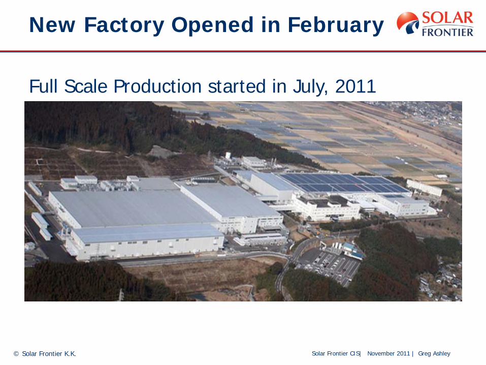
New Factory Opened in February
© Solar Frontier K.K.
Full Scale Production started in July, 2011
Solar Frontier CIS| November 2011 | Greg Ashley
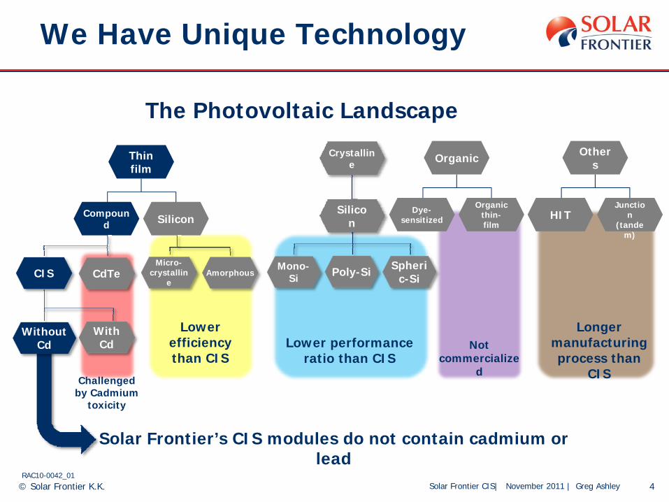
We Have Unique Technology
4RAC10-0042_01
Silicon
Crystalline
Others
HIT
Multi-Junctio
n (tande
m)
Organic
Dye-sensitized
Organic thin-film
Thin film
Compound Silicon
Micro-crystallin
eAmorphous
Spheric-SiPoly-SiMono-
Si
With Cd
Without Cd
CdTeCIS
Lower efficiency than CIS
Challenged by Cadmium
toxicity
Not commercialize
d
Lower performance ratio than CIS
Longer manufacturing process than
CIS
Solar Frontier’s CIS modules do not contain cadmium or lead
The Photovoltaic Landscape
© Solar Frontier K.K.

Solar Frontier CIS| November 2011 | Greg Ashley
What is CIS?
5© Solar Frontier K.K.
CIS is a thin-film compound-semiconductor PV consisting of three major elements:
Cu CopperIn IndiumSe SeleniumSometimes called “CIGS” since portions of In are replaced by Ga
Crystal structure of CIS(Chalcopyrite structure)
Cu
In*
Se**
* Partially Ga** Partially S
Solar Frontier CIS| November 2011 | Greg Ashley
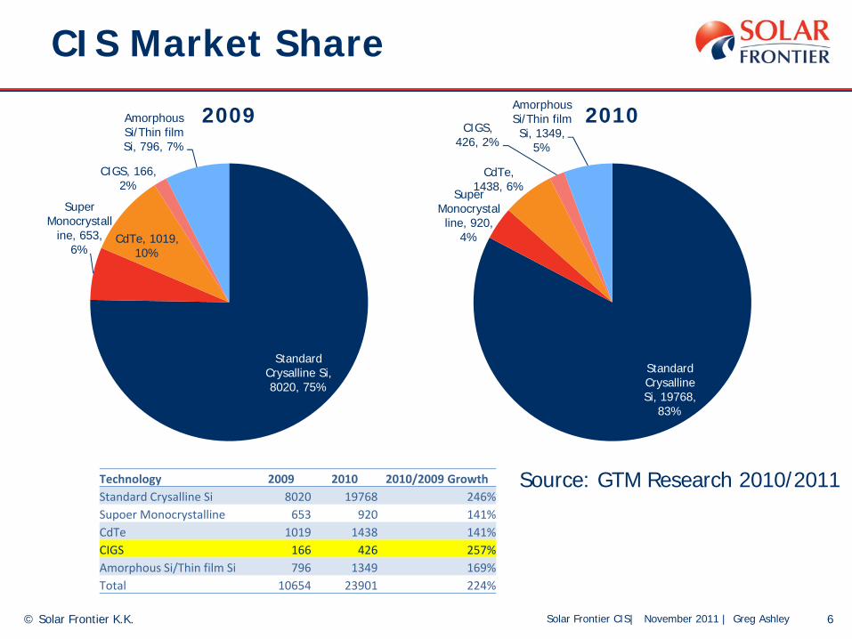
CIS Market Share
6© Solar Frontier K.K.
Source: GTM Research 2010/2011
Standard Crysalline Si, 8020, 75%
Super Monocrystall
ine, 653, 6%
CdTe, 1019, 10%
CIGS, 166, 2%
Amorphous Si/Thin film Si, 796, 7%
2009
Standard Crysalline Si, 19768,
83%
Super Monocrystalline, 920,
4%
CdTe, 1438, 6%
CIGS, 426, 2%
Amorphous Si/Thin film Si, 1349,
5%
2010
Technology 2009 2010 2010/2009 GrowthStandard Crysalline Si 8020 19768 246%Supoer Monocrystalline 653 920 141%CdTe 1019 1438 141%CIGS 166 426 257%Amorphous Si/Thin film Si 796 1349 169%Total 10654 23901 224%

Solar Frontier CIS| November 2011 | Greg Ashley
General View of “Thin Film”
7© Solar Frontier K.K.
Low efficiency: Commercially available CIS modules have an efficiency over 13% and on track to be greater than 14% (~ c-Si)
Thin Film = Frameless:CIS modules have framed and frameless types available.
Polarity Sensitive (Negative grounding required):Negative grounding is required only for superstrate structure (CdTe, a-Si) where TCO is deposited on cover glass.CIS is not polarity sensitive (substrate structure)
Initial degradation (LID):CIS does not have initial LID as a-Si. On the contrary, CIS has initial output improvement (+5-10%) by light soaking effect.
CIS (or CIGS) is not the same as CdTe or a-Si.
Solar Frontier CIS| November 2011 | Greg Ashley
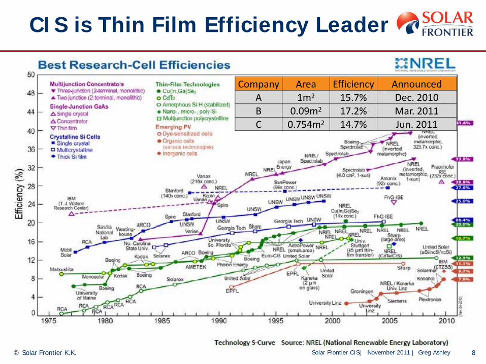
CIS is Thin Film Efficiency Leader
8© Solar Frontier K.K.
Company Area Efficiency AnnouncedA 1m2 15.7% Dec. 2010B 0.09m2 17.2% Mar. 2011C 0.754m2 14.7% Jun. 2011

Solar Frontier CIS| November 2011 | Greg Ashley
Product Development Roadmap
2010 2011 2012 20132014
18%
14%
13%
12%
11%
Module Efficiency
16.3%
17.2%
© Solar Frontier K.K.
Shipping
Achieved

Solar Frontier CIS| November 2011 | Greg Ashley
World Record Efficiency
Module efficiency of 17.20% achieved at the Atsugi Research Center on 30 cm X 30 cm moduleHighest thin-film module efficiency in the world
© Solar Frontier K.K.
Efficiency (%) 17.20
Voc (cell/V) 0.693
Jsc (mA/cm2) 34.60
Fill Factor 0.716
Area (cm2) 808

Solar Frontier CIS| November 2011 | Greg Ashley
SF155
11
Dimensions: 49.5 x 38.5 x 1.4 inch
(1,257 x 977 x 35 mm)
Pmax: 155 W
PTC : 140.4W
Efficiency: 12.6%
Frame: Anodized Aluminum Alloy
© Solar Frontier K.K.

Solar Frontier CIS| November 2011 | Greg Ashley
CIS Module Structure
12© Solar Frontier K.K.
1. Proven Technology for Durability
Cover glass and backsheetAluminum frame (less risk of glass damage, mounting felxibility) Wind/Temp/Humidity environmental durability
2. Not Polarity sensitiveCover glass
Frame
Sealing material
BacksheetEncapsulant
Tempered Cover glass
Backsheet
CIS substrate
Encapsulant
Encapsulant
TCOBuffer layerLight-Absorbing layer
Mo electrodeGlass
Superstrate type (a-Si, CdTe)
CIS
Superstrate glass
Encapsulant
Backside cover (glass)
-+
TCOa-Si or CdTe
Solar Frontier CIS| November 2011 | Greg Ashley
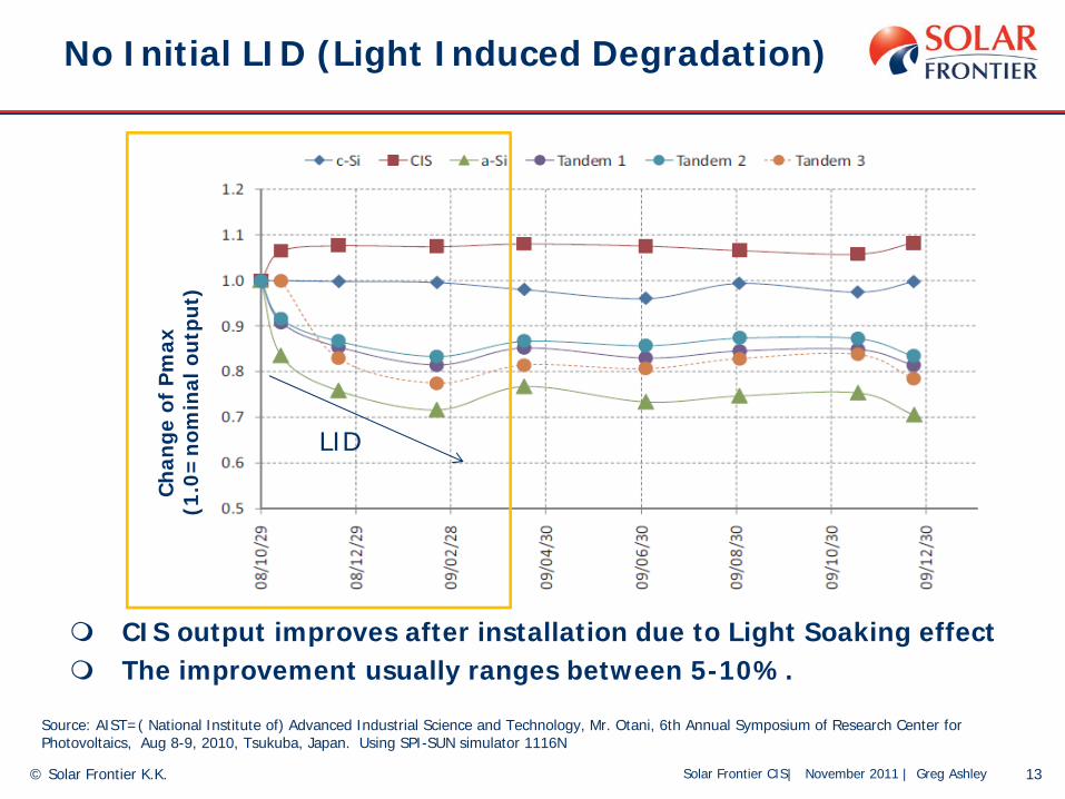
No Initial LID (Light Induced Degradation)
13© Solar Frontier K.K.
Source: AIST=( National Institute of) Advanced Industrial Science and Technology, Mr. Otani, 6th Annual Symposium of Research Center for Photovoltaics, Aug 8-9, 2010, Tsukuba, Japan. Using SPI-SUN simulator 1116N
Cha
nge
of P
max
(1.0
=no
min
al o
utpu
t)
CIS output improves after installation due to Light Soaking effectThe improvement usually ranges between 5-10%.
LID

Solar Frontier CIS| November 2011 | Greg Ashley
Other Benefits
14© Solar Frontier K.K.
High performance ratioLight Soaking Effect, Broader Spectra Response and Temperature Coefficient increase Performance Ratio
EcologicalNon-toxic (contains no Cd and uses Pb-free solder)Reusable packaging and reduced on-site wasteLower overall energy consumption in the manufacturing process (less than 1 year energy payback time)
NOTE: Performance ratio PR (%)Performance ratio means “the relationship between actual yield and target yield”
Actual output from installed capacity (kWh)
Installed Capacity (kW) xActual Radiation (kWh/m2)
1 sun (1kW/m2)

Solar Frontier CIS| November 2011 | Greg Ashley 15© Solar Frontier K.K.
March 18, 2010 | Shyam Mehta Thin Film 2010: Market Outlook to 2015 Executive Summary
Thin Film Performs Best
Solar Frontier CIS| November 2011 | Greg Ashley
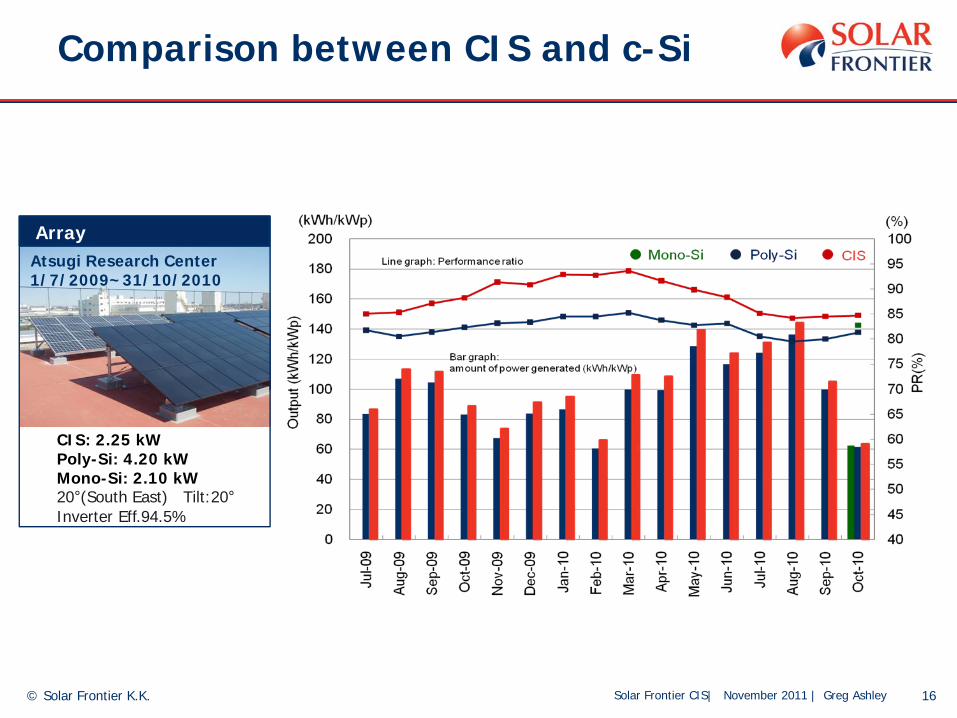
Comparison between CIS and c-Si
16© Solar Frontier K.K.
CIS: 2.25 kW Poly-Si: 4.20 kWMono-Si: 2.10 kW20°(South East) Tilt:20°Inverter Eff.94.5%
Atsugi Research Center1/7/2009~31/10/2010
Array

Solar Frontier CIS| November 2011 | Greg Ashley
Performance Comparison between CIS and CdTe
17
Array
- Site: Atsugi Research Center- Data period: February 2011~June 2011
CIS: 3.12 kW CdTe: 3.6 kW
0°(South) Tilt:20°Inverter Eff.94.5%
Module type
- CIS (Solar Frontier)SF-130 (130W)
- CdTe (75W)
96.1%
89.9%
92.0%
86.6%
Feb, 2011~ June, 2011
Total Irradiation: 630 kW/m2

Solar Frontier CIS| November 2011 | Greg Ashley
Effect of Efficiency
18© Solar Frontier K.K.
c-Si Typical
0%
10%
20%
30%
40%
50%
60%
70%
80%
90%
100%
110%
120%
10.0% 11.0% 12.0% 13.0% 14.0% 15.0%
Module Price to keep same kWh cost (14.4% is 100%)
10.5%
11.5%
12.5%
13.5%
14.4%
Assumption: 5MW ground mount, fixed BOS $0.75/Wp and area dependent BOS $1.33/WpIf the module efficiency is only variable (same physical size, same performance ratio etc.)Re
lativ
e M
odul
e Pr
ice
(per
Wp)
Module Efficiency

Solar Frontier CIS| November 2011 | Greg Ashley
Importance of Performance Ratio
19© Solar Frontier K.K.
c-Si TypicalSF140SF145SF150SF155
SF160
0%
10%
20%
30%
40%
50%
60%
70%
80%
90%
100%
110%
120%
10.0% 11.0% 12.0% 13.0% 14.0% 15.0%
Module Price to keep same kWh cost (c-Si price is 100%)
c-Si
CIS
+5% PR(+5%kWh)
4.76MW CIS system delivers the same kWh as
5MW c-Si System 11.4 11.8 12.2 12.6 13.0
Rela
tive
Mod
ule
Pric
e (p
er W
p)
Module Efficiency
Solar Frontier CIS| November 2011 | Greg Ashley
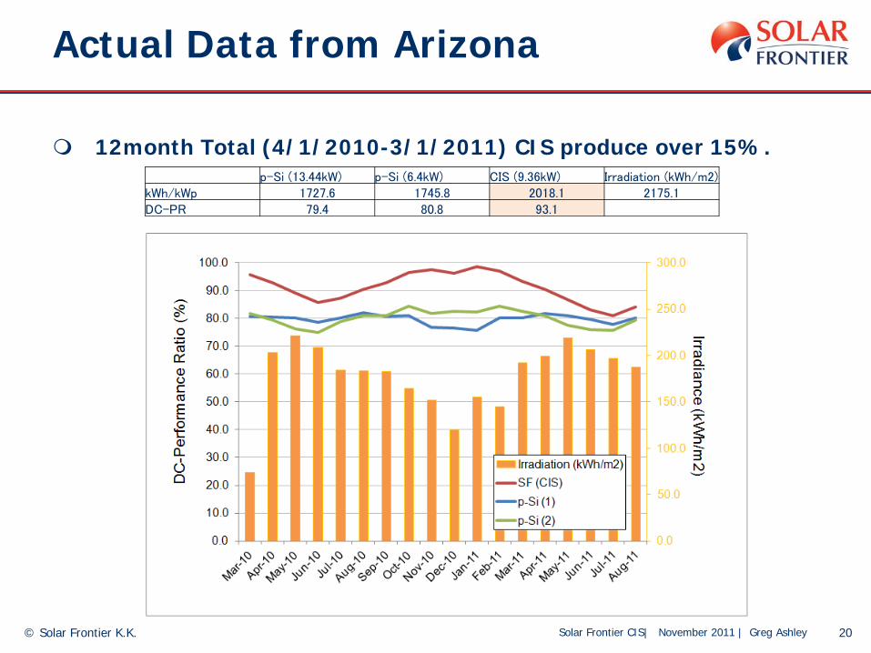
Actual Data from Arizona
12month Total (4/1/2010-3/1/2011) CIS produce over 15%.
20© Solar Frontier K.K.
p-Si (13.44kW) p-Si (6.4kW) CIS (9.36kW) Irradiation (kWh/m2)kWh/kWp 1727.6 1745.8 2018.1 2175.1DC-PR 79.4 80.8 93.1

Solar Frontier CIS| November 2011 | Greg Ashley
Under partially shaded conditions, the unique patterning of CIS modules keeps the drop of output to a minimum
0
20
40
60
80
0 20 40 60 80 100Pm
(W
)Shade Area (%)
The data presented in this document is the proprietary information of Solar Frontier K.K. and is intended for discussion purposes only.Solar Frontier does not intend to warranty any data beyond the performance specifications of CIS modules as indicated in their respective specification datasheets..
CIS
There is a partial loss of output but the overall effect is minimum
c-Si
The module’s output drops significantly under partial shadow
CIS
c-Si
shadowshadow
Shadow Tolerance
21© Solar Frontier K.K.

Solar Frontier CIS| November 2011 | Greg Ashley
Energy Payback Time
22
Energy Payback Time (EPT): the time required for a module to generate the amount of energy spent in its productionCIS modules have a faster EPT than conventional silicon
0.5
1
1.5
Crystalline Silicon
Amorphous Silicon
CIS
Yea
rs
Source: New Energy and Industrial Technology Development Organization (NEDO)
© Solar Frontier K.K.

Solar Frontier CIS| November 2011 | Greg Ashley
Ground mount and rooftop systems
23
Kolitzheim, Germany (550 kWp)
Nissan Motors Headquarters, Japan (40 kWp)Schwabach, Germany (385 kWp)
Coalinga, California (1.2 MWp)
© Solar Frontier K.K.

Solar Frontier CIS| November 2011 | Greg Ashley
Rooftop Systems
24
Commercial rooftop, Japan Commercial rooftop, Italy
Residential rooftop, AustraliaResidential rooftop, Germany
© Solar Frontier K.K.
Solar Frontier CIS| November 2011 | Greg Ashley
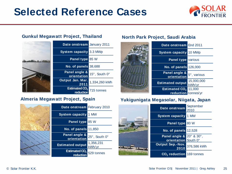
Selected Reference Cases
25© Solar Frontier K.K.
Date onstream January 2011
System capacity 3.3 MWp
Panel type 85 W
No. of panels 38,688
Panel angle & orientation 15°, South 0°
Output Jan. Mar. 2011 1,334,260 kWh
Estimated CO2reduction 715 tonnes
Gunkul Megawatt Project, Thailand
Date onstream End 2011
System capacity 10 MWp
Panel type various
No. of panels 126,000
Panel angle & orientation 5°, various
Estimated output 15,000,000 kWh/yr
Estimated CO2reduction
11,000 tonnes/yr
North Park Project, Saudi Arabia
Date onstream February 2010
System capacity 1 MW
Panel type 85 W
No. of panels 11,850
Panel angle & orientation 25°, South 0°
Estimated output 1,356,231 kWh/yr
Estimated CO2reduction 529 tonnes
Almeria Megawatt Project, Spain
Date onstream September 2010
System capacity 1 MW
Panel type 80 W
No. of panels 12,528
Panel angle & orientation
20° & 30°, South 0°
Output Sep.-Nov.2010 376,586 kWh
CO2 reduction 169 tonnes
Yukigunigata Megasolar, Niigata, Japan

Solar Frontier CIS| November 2011 | Greg Ashley© Solar Frontier K.K.
Thank You!


