
Standby Power Rating150 kW 60Hz
Includes: • Naturally Aspirated Gaseous Fueled 4.6L Engine• Two line LCD tri-lingual digital Nexus™ controller• Isochronous electronic governor• Closed coolant recovery system• Smart battery charger• UV/Ozone resistant hoses• ±1% voltage regulation• Natural gas or LP operation• 2 year limited warranty• UL 2200 Listed• Meets EPA emission regulations
Catalog Numbers:• SGN150RGAE / SGN150RPAE 120/240V, 1-phase• SGN150CGAE / SGN150CPAE 120/208V, 3-phase• SGN150JGAE / SGN150JPAE 120/240V, 3-phase• SGN150IGAE / SGN150IPAE 277/480V, 3-phase
Meets 2010 EPA emissions regulations.Meets CA/MA emissions requirements with factory-installed catalyst.
Features • Total commitment to component testing, reliability testing, environmental testing, destruction and life testing, plus testing to applicable CSA, NEMA, EGSA, and other standards.
• Test criteria: - Prototype tested - NEMA MG1-22 evaluation - System torsional tested - Motor starting ability
• Solid-state, frequency compensated voltage regulation This state-of-the-art power maximizing regulation system is standard on all Siemens models. It provides optimized fast response to changing load conditions and maximum motor starting capability by electronically torque- matching the surge loads to the engine. An unequalled ±1% voltage regulation.
Data Sheet
Siemens Liquid Cooled Standby Generators 150 kW Liquid Cooled Gas Engine
usa.siemens.com/generators

Application & Engineering Data
Generator Specifications
Type Synchronous
Rotor insulation Class F or H (see Data Label)
Stator insulation Class H
Telephone interference factor (TIF) <50
Alternator output leads 3 phase 6 / 4 wire
Bearings Sealed Ball
Coupling Gear drive
Load capacity (standby rating) 150 kW
Exitation system Brushless
Voltage Regulation
Type Full Digital
Sensing Three Phase
Regulation ± 0.25%
Generator Features
Revolving field heavy duty generator
Directly connected to the engine
Operating temperature rise 120 °C above a 40 °C ambient
Insulation is Class F rated at 130 °C rise
All models are fully prototyped tested
Enclosure Features
Aluminum weather protective enclosure
Ensures protection against mother nature.Electrostatically applied textured epoxy paint for added durability.
Enclosed critical grade muffler
Quiet, critical grade muffler is mounted inside the unit to prevent injuries.
Small, compact,attractive
Makes for an easy,eye appealing installation.
Engine Specifications
Make Generac
Model V-type
Cylinders 10
Displacement 6.8 Liter
Bore 3.55
Stroke 4.17
Compression ratio 9:1
Intake air system Naturally Aspirated
Valve seats Hardened
Lifter type Hydraulic
Governor Specifications
Type Electronic
Frequency regulation Isochronous
Steady state regulation ± 0.25%
Engine Lubrication System
Oil pump Gear
Oil filter Full flow spin-on cartridge
Crankcase capacity 5 Quarts
Engine Cooling System
Type Closed
Water pump Belt driven
Fan speed 2200
Fan diameter 26 inches
Fan mode Puller
Fuel System
Fuel type Natural gas,propane vapor
Carburetor Down draft
Secondary fuel regulator Standard
Fuel shut off solenoid Standard
Operating fuel pressure 11” - 14” H2O
Electrical System
Battery charge alternator 12V 30 Amp
Static battery charger 12V 2 Amp
Recommended battery Group 24F, 525CCA
System voltage 12 Volts
Rating definitionsStandby: Applicable for supplying emergency power for the duration of the utility power outage. No overload capability is available for this rating. (All ratings in accordance with BS5514, ISO3046 and DIN6271). (All ratings in accordance with BS5514, ISO3046, ISO8528, SAE J1349 and DIN6271).
2

Operating Data
KW rating (LP/NG) 150
Engine size 6.8 Liter, V10
Catalog Numbers Generator Output Voltage/kW - 60Hz LP AMP NG AMP CB Size
SGN150RGAE/SGN150RPAE 120/240V, 1-phase, 1.0 pf 144 600 136 567 700
SGN150CGAE/SGN150CPAE 120/208V, 3-phase, 0.8 pf 150 520 142 493 600
SGN150JGAE/SGN150JPAE 120/240V, 3-phase, 0.8 pf 150 451 142 427 500
SGN150IGAE/SGN150IPAE 277/480V, 3-phase, 0.8 pf 150 225 142 214 250
Generator Locked Rotor KVA Available At Voltage Dip Of 35%
Single phase or 208-240 3-phase 320
480V 3-phase 350
Engine Fuel Consumption (Natural Gas) (Propane)Natural Gas
(ft3/hr.)Propane
(gal/hr.) cu ft/hr
Exercise cycle 155 1.7 63
25% of rated load 556 6.09 224
50% of rated load 1070 11.72 431
75% of rated load 1491 16.33 600
100% of rated load 2061 22.57 830
For Btu content, multiply ft3/hr x 2520 (LP) or ft3/hr x 1000 (NG)
Engine Cooling
Air flow (inlet air including alternator and combustion air) ft3/min. 7,800
System coolant capacity US gal. 4.5
Heat rejection to coolant BTU/hr. 568,000
Max. operating air temp. on radiator °C (°F) 60 (150)
Max. ambient temperature °C (°F) 50 (140)
Combustion Air Requirements
Flow at rated power 60 Hz cfm 410
Sound Emissions In DBA
Exercising at 7 meters 66
Normal operation at 7 meters 79
Exhaust
Exhaust flow at rated output 60 Hz cfm 1,535
Exhaust temp. at muffler outlet °C (°F) 593 (1100)
Engine Parameters
Rated synchronous RPM 60 Hz 3600
Power Adjustments For Ambient Conditions
Temperature deration
3% for every 10 °C above - °C 25
1.65% for every 10 °F above - °F 77
Altitude deration
1% for every 100 m above - m 182
3% for every 1000 ft. above - ft. 600
RATING: All three phases units are rated at 0.8 power factor. All single phase units are rated at 1.0 power factor. STANDBY RATING: Standby ratings apply to installations served by a reliable utility source. The standby rating is applicable to varying loads for the duration of a power outage. There is no overload capability for this rating. Ratings are in accordance with ISO-3046-1. Design and specifications are subject to change without notice.kW rating is based on LPG Fuel and may derate with natural gas.
3

Interconnections
Circuit breaker wire and conduit size
kW Volts CB Amps Lug size
150 240 1 Ø 700 (3) 1/0 to 500 mcm
150 240 3 Ø 500 (3) 2/0 to 400 mcm
150 208 3 Ø 600 (3) 2/0 to 400 mcm
150 480 3 Ø 250 (1) 600 mcm to #4 or (2) 250 mcm to 1/0
SGN SERIES ENGINE GENERATORCONNECTION PANEL
SL TRANSFER SWITCH
Interconnections
Circuit breaker wire and conduit size
kW Volts CB Amps Lug size
150 240 1 Ø 700 (3) 1/0 to 500 mcm
150 240 3 Ø 500 (3) 2/0 to 400 mcm
150 208 3 Ø 600 (3) 2/0 to 400 mcm
150 480 3 Ø 250 (1) 600 mcm to #4 or (2) 250 mcm to 1/0
4

SGN SERIES ENGINE GENERATORCONNECTION PANEL
SL TRANSFER SWITCH
Interconnections
Circuit breaker wire and conduit size
kW Volts CB Amps Lug size
150 240 1 Ø 700 (3) 1/0 to 500 mcm
150 240 3 Ø 500 (3) 2/0 to 400 mcm
150 208 3 Ø 600 (3) 2/0 to 400 mcm
150 480 3 Ø 250 (1) 600 mcm to #4 or (2) 250 mcm to 1/0
Nexus Control Features
2-line plain text LCD display Simple user interface for ease of operation
Mode Switch-Auto Automatic start on utility failure. 7 day exerciser
-Off Stops unit. Power is removed. Control and charger still operate.
-Manual/Test (start)Start with starter control, unit stays on.
If utility fails, transfer to load takes place.
Programmable start delay between 10-30 seconds Standard
Engine start sequence Cyclic cranking: 16 sec. on, 7 rest (90 sec. maximum duration)
Engine warm-up 5 seconds
Engine cool-down 1 minute
Starter lock-out Starter cannot re-engage until 5 sec. after engine has stopped.
Smart battery charger Standard
Automatic voltage regulation with overand under voltage protection
Standard
Automatic low oil pressure shutdown Standard
Overspeed shutdown Standard, 72Hz
High temperature shutdown Standard
Overcrank protection Standard
Safety fused Standard
Failure to transfer protection Standard
Low battery protection Standard
50 event run log Standard
Future set capable exerciser Standard
Incorrect wiring protection Standard
Internal fault protection Standard
Common external fault capability Standard
Governor failure protection Standard
*Single and three phase connections may vary, refer to the owner’s manual for specific connection information.
5
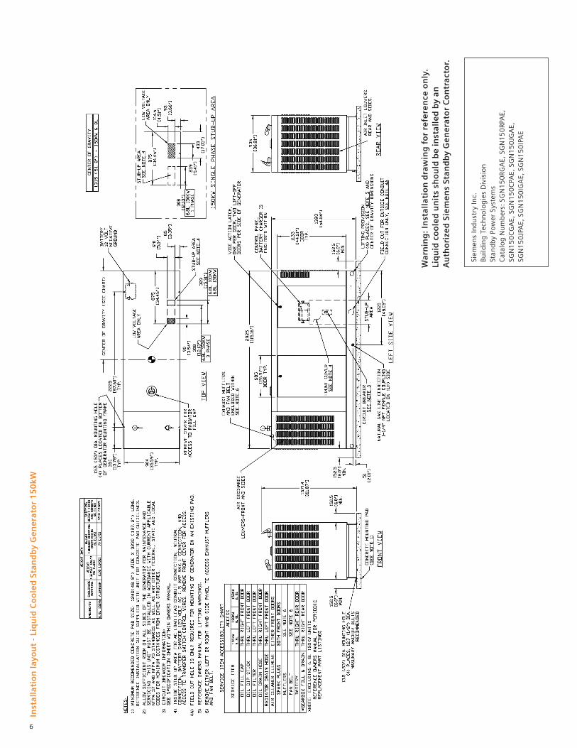
Inst
alla
tio
n la
you
t -
Liq
uid
Co
ole
d S
tan
db
y G
en
era
tor
15
0kW
War
nin
g: I
nst
alla
tio
n d
raw
ing
fo
r re
fere
nce
on
ly.
Liq
uid
co
ole
d u
nit
s sh
ou
ld b
e in
stal
led
by
anA
uth
ori
zed
Sie
me
ns
Stan
db
y G
en
era
tor
Co
ntr
acto
r.
Siem
ens
Ind
ust
ry In
c.B
uild
ing
Tec
hn
olo
gie
s D
ivis
ion
Stan
db
y Po
wer
Sys
tem
sC
atal
og
Nu
mb
ers:
SG
N1
50
RGA
E, S
GN
15
0RP
AE,
SG
N1
50
CG
AE,
SG
N1
50
CPA
E, S
GN
15
0JG
AE,
SG
N1
50
JPA
E, S
GN
15
0IG
AE,
SG
N1
50
IPA
E
6

Notes:
7

Published by Siemens 2017
Siemens Industry, Inc. 5400 Triangle Parkway Norcross, GA 30092 1-800-241-4453 [email protected] Order No. RPFL-QT150-1117-CP Printed in USA All Rights Reserved © 2017, Siemens Industry, Inc. usa.siemens.com/generators
The technical data presented in this document is based on an actual case or on as-designed parameters, and therefore should not be relied upon for any specific application and does not constitute a performance guarantee for any projects. Actual results are dependent on variable conditions. Accordingly, Siemens does not make representations, warranties, or assurances as to the accuracy, currency or completeness of the content contained herein. If requested, we will provide specific technical data or specifications with respect to any customer’s particular applications. Our company is constantly involved in engineering and development. For that reason, we reserve the right to modify, at any time, the technology and product specifications contained herein.


