
Geotechnical Report Shotgun Cove Road Improvements
Whittier, Alaska
NOVEMBER 2004
Submitted To: Arctic Slope Consulting Group
3900 C Street. Suite 501 Anchorage, Alaska 99503
By: Shannon & Wilson, Inc.
5430 Fairbanks Street, Suite 3 Anchorage, Alaska 99518
Phone: 907-561-2120 Fax: 907-561-4483
E-mail: [email protected]
Project Number: 32-1-01657
SHOTGUN COVE ROAD STATION 98+00 TO 104+00
PAGES HAVE BEEN REMOVED FROM APPENDICES A, B, AND C BEARING DATA FROM EXPLORATION BEYOND THE PROJECT LIMITS.
(5/12/2015)

SHANNON & WILSON, INC.
APPENDIX A
PLAN AND PROFILE SHEETS
TABLE OF CONTENTS
Section A.1 Subsurface Investigation
A 1.1 Geotechnical Borings A 1.1.1 Soil Sampling A 1.1.2 Rock Sampling·
A2 Surface Reconnaissance
LIST OF FIGURES
Page A-1 A-1 A-2 A-2 A-3
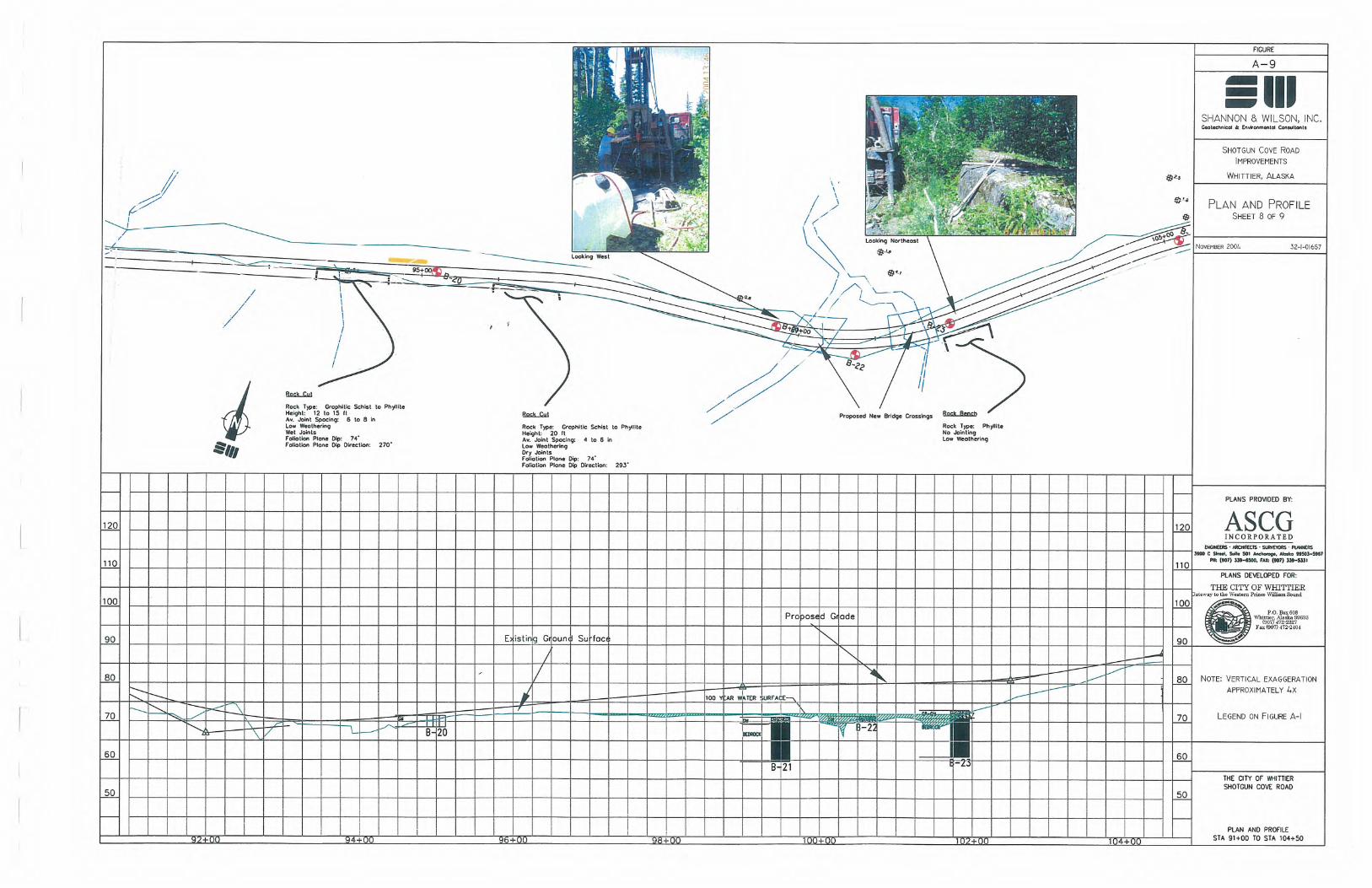
Figure A-1 Figures A-2 through A-10
Plan and Profile Sheet Legend Plan and Profile Sheets
32-1-01657

SHANNON & WILSON, INC.
The Shotgun Cove Road Improvement Project is located along approximately 2 miles of Shotgun
Cove Road extending from the east end of Whittier. The purpose of the explorations described
below is to provide a banlc of subsurface information that can be used in the design/build phase
of tllis project. The information included herein should be considered a starting point as
adjustments from the currently proposed alignment later in the project life or other data needs
may require additional explorations along the project alignment.
A.l Subsurface Investigations
Subsurface explorations consisted of advancing and sampling 33 soil borings designated Borings
B-01 through B-32 to evaluate subsurface conditions. Borings B-06 through B-08 and Borings
B-21 and B-23 were advanced at bridge abutment locations. Borings B-26 through B-29 vvere
advanced along Salmon Run Road and Borings B-30 through B-32 were advanced along
Blackstone Road. The remaining borings were generally advanced every 400 to 500 feet along
the existing alignment of Shotgun Cove Road. The approximate locations of these explorations
are included on the plan and profile sheets in Appendix A. Logs of the borings are included in
Appendix B.
A.l.l Geotechnical Borings
Borings were conducted at many locations along the road alignment for several purposes.
Borings located at the bridge abutments were drilled to bedrock and were advanced at least 7 feet
into bedrock so that bedrock could be confirmed and classified. Borings positioned near boggy
areas were intended to evaluate the peat thickness and to classify the nature of the soils beneath
the surface organics. The remaining borings were advanced through the road prism and/or
embankment fill areas to auger refusaL
Drilling services for this project were provided by Discovery Drilling, of Anchorage, Alaska,
using a track mounted CME 55-drill rig. Through soils, borings were advanced with 3-1 I 4- inch
inner diameter (ID), continuous-flight, hollow-stem augers. In the borings at bridge abutment
locations, rock coring was used to sample and confirm bedrock. This was accomplished using an
A W-34 (34 mm I 1.3 inch inner diameter) core barrel.
An experienced geologist from Shannon & Wilson was present continuously during the field
work to locate the borings, observe drilling operations, recover soil samples, and log the
GEOTECHNICAL REPORT Shotgun Cove Road Improvements, Whittier, Alaska ASCG
November 2004 Page A-1
32-1-01657

SHANNON & WILSON, INC.
subsurface conditions encountered in each boring. At the completion of the borings, they were
backfilled using the cuttings removed during the drilling activity.
A.l.l.l Soil Sampling
As a boring was advanced through soil, sampling was generally accomplished at 5-foot depth
intervals using Standard Penetration Test procedures. With this method, a 2-inch outside
diameter (OD) split-spoon sampler is advanced 18 or 24 inches into the undisturbed soil at the
bottom of the boring, with blows ·of a 140-pound surface hammer falling 30 inches on the drill
rods. The number of blows required to produce the finall2 inches of an 18-inch penetration of
the hammer or the middle 12 inches of a 24-inch penetration, defined as the Standard Penetration
Resistance, was recorded for each sample. When hard or very dense soils, coarse gravel or
bedrock were encountered, the sampler often could not be driven the full 18 inches, or in some
cases even 12 inches. The blow counts, which are noted on the logs, are uncorrected values and
provide a means of evaluating the relative density (compactness) or consistency (stiffness) of
cohesionless or cohesive soils, respectively. When a full 18 inches penetration was not
achieved, blows and the penetration achieved are recorded on the logs.
A.l.l.2 Rock Sampling
Where applicable, bedrock was confirmed by using a 5 foot long BQ core barrel with a diamond
impregnated bit and wire line coring methods. Continuous 1-5/8-inch diameter core extracted
from each 5 foot or less run was classified in the field by our geologist, who also placed the core
in two-foot long core boxes. The depths of the top and bottom of each run, percent recovery, and
other drilling notes were recorded. Bedrock was assumed if at least 5 feet of continuous,
moderate quality return was achieved. Recovered cores were delivered to our Anchorage
laboratory for further classification, testing and photographing. Photographs of the core samples
collected during our explorations are presented in Appendix B on the Rock Core Logs.
A.2 Surface Reconnaissance
Surface reconnaissance was performed along the project alignment to characterize ground
conditions that may be encountered during the constmction of the road improvements. This
effort included generalized surveys of exposed rock cuts along Shotgun Cove Road.
GEOTECHNICAL REPORT Shotgun Cove Road Improvements, Whittier, Alaska ASCG
November 2004 Page A-2
32-l-01657

SHANNON & WILSON, INC.
At the major rock outcrops observed along the existing roadway, generalized bedrock mapping
was performed. At each mapping site, information regarding the exposed rock type(s), major
joint set(s) orientation, and average joint spacing were recorded. Photographs were also taken of
each of these sites. Information is presented on the plan and profile sheets in Appendix A.
GEOTECHNICAL REPORT Shotgun Cove Road Improvements, Whittier, Alaska ASCG
November 2004 Pasze A-3
32-1 .:-o 1657


Rock Core Log for Boring B-21
1.5
3.5
5.5
7.5
9.5
11.5
80%Recovery
100%Recovery
100%Recovery
RQD=21%
RQD=28%
RQD=22%
Gray, phyllite (metamorphosed shale) with weak foliation.Highly weathered (incompetant) section.
Aver
age
Joint
Spa
cing
Dom
inant
Joint
Ang
lesBe
dding
Ang
lesFo
liatio
n Ang
les
Relat
ive H
ardn
ess
Effe
rves
cenc
e
Joint
Sm
ooth
ness
Joint
Infill
ing
Degr
ee o
f
Wea
ther
ing
CORERUN
ftbgs DESCRIPTION
N/A
N/A
N/A
mo
d
none
roug
h
none
high
S2
S3
S 4
1.5
8.9
11.5
Gray, phyllite (metamorphosed shale) with weak foliation.Moderate to highly weathered. Zone of quartz strands and
cross cutting quartz stringers from 9.2 - 10.2 ft. bgs.
4 -
5 in
ches
65 d
egre
es
60 -
90
degr
ees
mod
erat
e
none
roug
h
none
none
to
low
N/A
N/A
*Note:
1. Visual classification of smoothness of joint surfaces (smooth, moderately smooth, moderately rough, rough)2. Indicates effort required to scratch core surface with steel stylus (easy, moderate, hard)3. Visual classification of apparent weathering of core (none, low, moderate, high)
Shotgun Cove Road Improvements
Rock Core Log, Boring B-21
Whittier, Alaska
November 2004
Fig. B-39
32-1-01657
SHANNON & WILSON, INC.Geotechnical & Environmental Consultants
1 2
3
2.6
3.4
Gray, phyllite (metamorphosed shale) with weak foliation.Highly competant section with no apparent bedding and
very little to no quartz stringers.
Gray, phyllite (metamorphosed shale) with weak foliation.Porous quartz strand that cross cuts foliation from 3.4 - 6.4 ft.bgs. Thin quartz stringers that cross cut foliation throughout
section and asymmetrical folding from 7.8 - 8.9 ft. bgs.
4 in
40 d
eg
N/A
1@
10 d
eg
mo
dsm
ooth
none
mo
d
none
none
to lo
w
<1/
2 in
ch
N/A
N/A
20 -
50
degr
ees
roug
h
none
mod
erat
e
none
high

Rock Core Log for Boring B-23
2.2
4.2
6.2
8.2
10.2
12.2
81%Recovery
100%Recovery
91%Recovery
RQD=12%
RQD=39%
RQD=51%
Gray, graphitic schist (metamorphosed shale) withlow to moderate foliation. Highly sheared zone
and quartz stringers that cross cut foliation.
Aver
age
Joint
Spa
cing
Dom
inant
Joint
Ang
lesBe
dding
Ang
lesFo
liatio
n Ang
les
Relat
ive H
ardn
ess
Effe
rves
cenc
e
Joint
Sm
ooth
ness
Joint
Infill
ing
Degr
ee o
f
Wea
ther
ing
CORERUN
ftbgs DESCRIPTION
<1 in
ch
75 d
egre
es
80 d
egre
es
mod
erat
e
none
smoo
th o
vera
ll,
roug
h @
qua
rtz
cont
acts
none
mod
erat
e to
hig
h
S3
S4
S5
2.2
4.5
12.2
Gray, graphitic schist (metamorphosed shale) withlow to moderate foliation. Quartz stringers that crosscut foliation from 7.8 - 9.3 ft. bgs and a moderately
sheared zone from 7.2 - 7.5 ft. bgs. 4 in
ches
80 d
egre
es
80 d
egre
es
mod
erat
e
none
smoo
th
none
low
70-8
0 de
gree
s80
deg
rees
*Note:
1. Visual classification of smoothness of joint surfaces (smooth, moderately smooth, moderately rough, rough)2. Indicates effort required to scratch core surface with steel stylus (easy, moderate, hard)3. Visual classification of apparent weathering of core (none, low, moderate, high)
Shotgun Cove Road Improvements
Rock Core Log, Boring B-23
Whittier, Alaska
November 2004
Fig. B-40
32-1-01657
SHANNON & WILSON, INC.Geotechnical & Environmental Consultants
1 2
3


