
i
SHIELDING EFFECTIVENESS OF MESH WIRE FOR 50Hz MAGNETIC FIELD
IBTIHAL FAWZI EL-SHAMI
A report submitted in partial fulfilment of the requirement for the
award of the degree of Master of Electrical Engineering
Faculty of Electrical and Electronic Engineering
Universiti Tun Hussein Onn Malaysia
APRIL 2011

iv
Abstract
A wire mesh shield composed of thin conductive wires will influence the
behaviour of electromagnetic fields within it. Many researchers have investigated
electromagnetic field behaviour in solid metal, but little of this work has probed into
the effects of a wire mesh. The primary goal of this work is to design wire mesh
shielding under overhead power lines to investigate the electromagnetic energy
transmitted to the ground and possibly can exposed people under certain risk.
The electromagnetic shielding of wire-mesh screens is discussed in the
frequency range where the individual meshes are electrically small )1.0( λ<L . The
screen, whose meshes are assumed to be square, its applicability to the measurement
of mesh properties is described. The low-frequency magnetic shielding afforded by
mesh enclosures is considered. Because of the reactive character of the mesh surface,
the near field source shielding effectiveness decreases with increasing frequency.
The enclosure magnetic-field shielding effectiveness increases with increasing
frequency, but saturates at a maximum value that depends on the geometry of the
mesh size, and the mesh wire radius. The enclosure electrostatic-field shielding
effectiveness depends only on the enclosure and mesh geometries.
Experimentally, shielding effectiveness measurements have been performed.
The wire mesh Shields designed in different sizes to find the relation between mesh
size and shielding effectiveness.

v
Abstrak
Jaringan wayar yang diperbuat daripada wayar konduktif yang halus akan
mempengaruhi kesan medan electromagnet di persekitarannya. Terdapat ramai
penyelidik telah membuat kajian berhubung kesan medan electromagnet di dalam
besi padu, tetapi sedikit kajian dibuat terhadap jaringan wayar. Matlamat utama di
dalam kajian ini adalah untuk mereka kekebalan jaringan wayar di bawah talian
pencawang utama elektrik dan seterusnya menyiasat tenaga yang dihasilkan kepada
bumi dan juga kesan pada manusia.
Kekebalan skrin jaringan wayar dibincangkan di dalam julat frekuensi di mana
setiap satu jaringan mempunyai keluasan yang kecil )1.0( λ<L . Skrin yang
dihasilkan di dalam bentuk segi empat sama di dalam pengujian ini. Kekebalan
magnetik berfrekuensi rendah juga di ambil kira. Sumber medan yang berdekatan
akan mengurangkan sifat kekebalan apabila frekuensi meingkat. disebabkan sifatnya
yang reaktif pada permukaan jaringan ini. Walaubagaimanapun, kekebalan medan
magnet akan meningkat apabila frekuensi ditingkatkan tetapi akan tepu apabila
mencapai saiz geometri maksimum jaringan wayar teserbut. Untuk kekebalan
elektrostatik ianya bergantung hanya kepada geometri penutup dan jaringan wayar.
Melalui experiment, kekebalan effektif sudah diukur dan jaringan wayar dibuat
untuk mencari kaitan di antara saiz jaringan dan kekebalan effektif.

vi
TABLE OF CONTENTS
CHAPTER TITLE PAGE
TITLE i
DECLARATION ii
ACKNOWLEDGEMENT iii
ABSTRACT iv
ABSTRAK v
CONTENTS vi
LIST OF FIGURES xiii
LIST OF TABLES xvi
LIST OF ABBREVIATIONS AND ACRONYMS xvii
I INTRODUCTION 1
1.1 Project Background 1
1.2 Problem Statement 3
1.3 Project Objectives 4
1.4 Project Scopes 4

xi
II LITERATURE REVIEW 5
2.1 Introduction 5
2.2 Technology Development 5
2.3 The Review of Magnetic Shielding Theory 7
2.3.1 Field Theory 7
2.3.2 Near field and far field 8
2.3.3 Characteristic and wave impedances 9
2.4 Shielding effectiveness 11
2.4.1 Absorption loss 13
2.4.2 Reflection loss 14
2.4.3 Reflection loss in near field 17
2.4.4 Multiple Reflection in thin shield 18
2.4.5 Composite Absorption and Reflection Loss
in Magnetic Field 19
2.5 Wire Mesh Properties 20
2.5.1 Design of wire mesh shield 21
2.5.2 The size of apertures 22
2.6 Shielding Material 23
2.6.1 Mild Steel 23
2.6.2 Mild Steel Properties 23
2.7 Shielding Effectiveness of Wire Mesh Shield 24
III METHODOLOGY 28
3.1 Introduction 28
3.2 Analytical method 28
xii
3.3 Outdoor Experimental Research 29
3.4 Indoor Experimental Research 33
3.5 Experimental test to existing wire mesh shield 36
IV RESULTS AND ANALYSIS 38
4.1 Introduction 38
4.2 Analytical Result 38
4.2.1 The relation between SE and Frequency 38
4.2.2 The relation between SE and Area of apertures 41 4.2.3 The relation between SE and Thickness of wires 43 4.3 Outdoor Experimental Result 44
4.3.1 The impact of change in the size of apertures 45
4.4 Indoor Experimental Result 46
V CONCLUSION AND RECOMMENDATION 51
5.1 Conclusion 51
5.2 Recommendation 52
5.3 Benefits Gained 52
REFERENCES 53
APPENDIX 55

xiii
LIST OF FIGURES
FIGURE TITLE PAGE
2.1 The electric (Hertzian) dipole 7
2.2 Electric and magnetic field from loop current 8
2.3 wave impedance depends on the distance from the source 9
2.4 Wave propagation through shielding material 12
2.5 Absorption loss increases with frequency and with shield thickness. 14 2.6 An incident wave is partially reflected from, and partially transmitted through, an interface two media . 15 2.7 Partial reflection and transmission occur at both boundaries of a shield. 16 2.8 Reflection loss in a copper shield varies with frequency, distance from the source, and type of wave. 18 2.9 Multiple reflections occur in a thin shield; part of the wave is transmitted through the second boundary at each reflection. 19 2.10 Magnetic material used as a shield by providing a low-reluctance for the magnetic field, diverting It around the shielded region. 20 2.11 Geometry of the wire mesh. 21
2.12 An H-field which is predominantly Tangential close to a metallic screen 22 2.13 An E-field which will hit a metallic Screen at right angles 22
2.14 Multiple small openings are preferable to a single large one 23
2.15 Shielded EMC box designed with double wire-mesh geometry 25
xiv
FIGURE TITLE PAGE
3.1 0.5mx0.5m wire mesh shield 30
3.2 1mx1m wire mesh shield 30
3.3 2mx2m wire mesh shield 31
3.4 2mx2m wire mesh shield with area of apertures 6cmX6cm 32
3.5 2mx2m wire mesh shield with area of aperture 4cmX4cm 32
3.6 2mx2m wire mesh shield with area of aperture 2.5cmX2.5cm 33
3.7 Measurement of magnetic flux density to 240V transformer 33
3.8 Measurement of magnetic flux density, when wire mesh shield is present with 10cmx10cm area of apertures 34 3.9 Measurement of magnetic flux density, when wire mesh shield is present with 8cmx8cm area of apertures 34 3.10 Measurement of magnetic flux density, when wire mesh shield is present with 6cmx6cm area of apertures 35
3.11 Measurement of magnetic flux density, when wire mesh shield is present with 4cmx4cm area of apertures 35
3.12 Measurement of magnetic flux density, when wire mesh shield is present with 2cmx2cm area of apertures 36
3.13 Measurement of magnetic flux density under transmission line with wire mesh shield installed 37 3.14 Measurement of magnetic flux density under transmission line without wire mesh shield 37 4.1 SE calculated (H-field) for the aluminium wire mesh 39
4.2 SE calculated (H-field) for the copper wire mesh 40
4.3 SE calculated (H-field) for the Mild Steel wire mesh 40
4.4 SE calculated (H-field) for the brass wire mesh 41
4.5 SE calculated (H-field) for some material against area at 50Hz 42 4.6 SE calculated (H-field) for some material against the radius of wires at 50Hz 43 4.7 SE measured (B-field) of Three sizes of wire mesh shields 44

xv
FIGURE TITLE PAGE
4.8 SE measured (B-field) for the Mild Steel wire mesh shield at 50 Hz 45 4.9 SE Expected (B-field) for the Mild Steel wire mesh shield at 50 Hz 46 4.10 Magnetic flux density ( B ) measured at different point without wire mesh shield 47 4.11 Magnetic flux density ( B ) measured at different point, when wire mesh shield was present with 10cmx10cm area of apertures. 48 4.12 Magnetic flux density ( B ) measured at different point, when wire mesh shield was present with 8cmx8cm area of apertures. 48 4.13 Magnetic flux density ( B ) measured at different point, when wire mesh shield was present with 6cmx6cm area of apertures. 49 4.14 Magnetic flux density ( B ) measured at different point, when wire mesh shield was present with 4cmx4cm area of apertures. 49 4.15 Magnetic flux density ( B ) measured at different point, when wire mesh shield was present with 2cmx2cm area of apertures. 50
xvi
LIST OF TABLES
TABLE TITLE PAGE
3.1 Permeability and conductivity of some materials 29
4.1 SE calculated (H field) for some material at low frequency 39
4.2 SE calculated (H-field) for some material against area at 50Hz 42
4.3 SE calculated (H-field) for some material against the radius
of wires at 50Hz 43

xvii
LIST OF ABBREVIATIONS AND ACRONYMS
wZ - Wave Impedance
0Z - Characteristic Impedance
sZ - Shield Impedance
rμ - Relative Permeability
rσ - Relative Conductivity
SE - Shielding Effectiveness
A - Absorption Loss
R - Reflection Loss
B - Multiple Reflections
δ - Skin Depth
sL - Sheet Inductance Parameter
SR - DC Resistance of the Mesh Wires
sa - Length of Wire Mesh
wr - Radius of Wire Mesh
Sτ - Time Constant Characteristic of the Mesh
eτ - Time Constant Characteristic of the Enclosure
EMC - Electromagnetic Compatibility

1
CHAPTER I
INTRODUCTION
Today with the increasing use of electrical power, high magnetic fields of power
frequency are often encountered in our environment. Unwanted magnetic fields are a
problem when using sensitive measurement equipment. Moreover, there is deep
concern about the possible health hazards for persons being exposed to electric and
magnetic fields at low frequencies.
Magnetic field shielding refers to the shielding of near field magnetic fields.
Near field magnetic fields are frequently described as having a low impedance and,
therefore, do not easily reflect off low impedance metals. It is important to realize,
however, that near field magnetic fields are not plane waves, and their field
distribution is typically complex and source dependent. Shielding of magnetic fields is
usually difficult and expensive
1.1 Project Background
Electromagnetic waves consist of two components, a magnetic field (H) and an
electric field (E). Electric fields from power lines are relatively stable because line
voltage doesn't change very much. Magnetic fields change greatly as current changes
due to changing loads. A large current flows in a low-impedance source such as
transmission line or a wire loop or a transformer. Such sources are called magnetic
field sources. For low-impedance fields, less energy is reflected, and more is
absorbed, because the metal is closely matched to the impedance of the field, that is
why it is difficult to shield against magnetic field. The absorption loss is important

2
when the interference source is contained within a shielded enclosure because only
the absorption loss provides attenuation. In low-frequency, low-impedance circuits,
stray magnetic field can cause serious trouble. They are produced by motors,
transformers, and transmission line.
Electromagnetic shielding is an important factor in providing protection for
sensitive equipment in both military and civilian applications, such as sensors.
Undesirable radiation can cause electromagnetic interference (EMI), which can take
the form of damage or other unacceptable responses in operation. Shielding against
EMI is used to reduce radiated emissions from a system or reduce radiated
susceptibility of a system and the term often used for such a specification is shielding
effectiveness (SE). Fundamentally, SE is the ratio of the incident wave to the
transmission wave for either the electric field or magnetic field, whether in the near-
field or far-field.
In the area of electromagnetic compatibility (EMC), as a kind of common
structural material, the wire-mesh reinforcement are used widely and the shielding
effectiveness (SE) of the wire-mesh reinforcement becomes more and more important
with the more attention paid on the problem. Generally, the metallic wire structure is
lighter and less cost than metal board.

3
1.2 Problem Statements
With the increasing use of electrical power, high magnetic fields of power
frequency are often encountered in our environment. Unwanted magnetic fields are a
problem when using sensitive measurement equipment. Moreover, there is deep
concern about the possible health hazards for persons being exposed to electric and
magnetic fields at low frequencies.
To obtain an efficient low-frequency magnetic shield, a substantial amount of
shielding material is often required. In general, the choice of shield type and amount
of material depends on the required attenuation and on the dominating design criteria:
material cost, weight, size, access for maintenance, etc. The shape of the shield is in
many cases restricted by practical limitations, and only partial shielding may be
possible to use. This problem is often encountered when already-installed electrical
power equipment is to be shielded.
The main goal is then to obtain maximum attenuation with the shield
configuration that is possible to use. The shielding result depends on both the material
used and the shield and source geometry.

4
1.3 Project Objectives
1. To develop the formulation of magnetic field shielding (SE) effectiveness of
wire mesh at 50 Hz.
2. To enhance understanding on the dependence of the SE on various parameters
of the wire mesh.
3. To verify the SE of magnetic field of 50Hz with experimental measurements.
1.4 Project Scopes
The purpose of this project is create a methods and approaches to protect
people in public area to exposed to electromagnetic that produced from overhead
transmission line, in this project the wire mesh shield was design to reduce 50Hz
magnetic field, which produce from transformer. All the experiments have been done
in UTHM university substation.

5
CHAPTER II
LITERATURE REVIEW
2.1 Introduction
In the near field, the reflection loss to a low frequency magnetic field is small.
Because of multiple reflections, this effect is even pronounced in a thin shield. The
primary loss for magnetic field is absorption loss. Because both the absorption and
reflection loss are small at low frequencies, the total shielding effectiveness is low. It
is therefore difficult to shield low frequency magnetic fields. Additional protection
against low frequency magnetic field can be achieved only by providing a low
reluctance magnetic shunt path to divert the field around the circuit being protected.
2.2 Technology Developments
Solid enclosures have been studied extensively since the 1970s. Most of the
work focused on the penetration of EM fields through apertures in the walls of the
enclosure. Mendez [2] is an early piece of work that investigated insertion loss of a
rectangular enclosure with apertures containing an internal radiating source.
More recently, extensive work has been done by Robinson et al [8, 3] and
Sewell et al [6]. Building on some of his own previous work and mathematics from
[2], Robinson developed a numerical solution to model a cavity with an aperture and
its resulting shielding effect anywhere within the enclosure. Using transmission line

6
theory, Robinson and his colleagues’ considers only the TE10 mode, but is valid
above and below the first cut off frequency. Robinson’s numerical model also allows
for internal losses, the consideration of multiple apertures, and is a function of the
cavity and aperture dimensions.
Today, there exists a variety of methods to determine the electromagnetic fields
while considering multiple modes within an enclosure containing apertures. The
Method of Moments (MOM), the finite difference time domain (FDTD), and
transmission line matrix (TLM) are all techniques that have proven reliable [3, 6].
While each method is capable, there are often differences in the solutions depending
on the resolution chosen for the computer simulations and due to the methods
themselves. These methods were designed for predicting field strength inside simple
metallic structures with a limited number of apertures, and more importantly from an
external source.
Casey [4] provides an investigation into the shielding behaviour of wire-mesh
screens. In his work, Casey concluded that the plane-wave shielding effectiveness of a
mesh screen tended to decrease with an increasing frequency. This is opposite of a
solid metal sheet, whose shielding effectiveness increases as frequency does. When a
mesh was used to form an enclosure, the shielding effectiveness increased with
frequency, saturated at a maximum value, and then began to decrease. Casey also
developed equations to estimate the sheet impedance of a wire mesh screen, which
will be used on this Chapter. While Casey’s work provides insight into wire mesh, he
only considered a plane wave in the far field. Magnetic field within wire mesh will
primarily be dominated by the near field.

7
2.3 The Review of electromagnetic shielding Theory
This section shows important theory about electromagnetic shielding.
2.3.1 Field Theory
Time varying electric and magnetic fields will exist when the conductor
conducts ac current.
Fig 2.1: The electric (Hertzian) dipole [20]
The well-known mathematical forms of the time varying electric and magnetic field
as shown in equation (2.1) are Maxwell’s equations.
8
In equation (2.1), this conductor is the short-wire Conductor. (Conductor length (D) is
shorter than wavelength (λ))
D <<λ
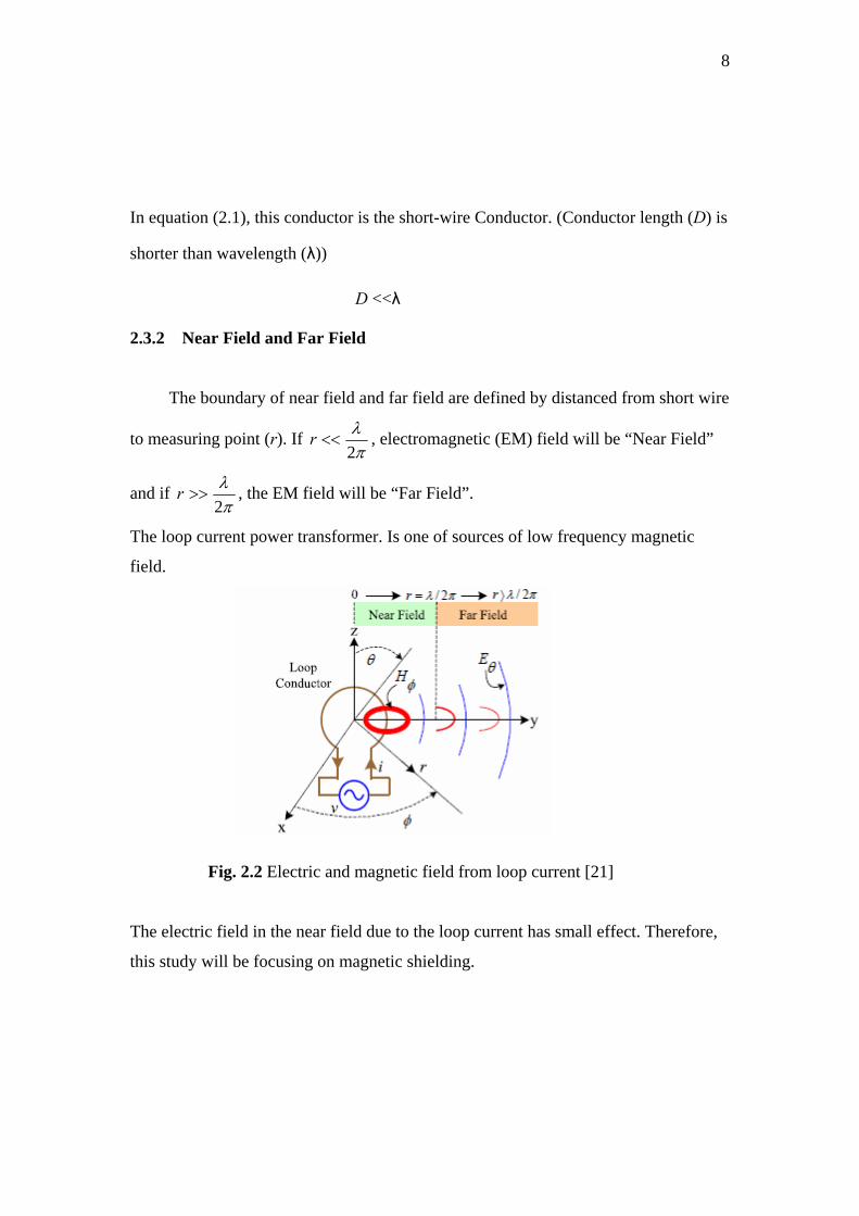
2.3.2 Near Field and Far Field
The boundary of near field and far field are defined by distanced from short wire
to measuring point (r). If πλ
2<<r , electromagnetic (EM) field will be “Near Field”
and if πλ
2>>r , the EM field will be “Far Field”.
The loop current power transformer. Is one of sources of low frequency magnetic
field.
Fig. 2.2 Electric and magnetic field from loop current [21]
The electric field in the near field due to the loop current has small effect. Therefore,
this study will be focusing on magnetic shielding.

9
2.3.3 Characteristic and wave impedances
For a rod or straight wire antenna, the source impedance is high. The wave
impedance near the antenna predominantly an electric field is also high. As distance is
increased, the electric field loses some of its intensity as it generates a complementary
magnetic field. In near field, the electric field attenuated at a rate of 3)1( r , whereas
the magnetic filed attenuates at a rate of 2)1( r . Thus, the wave impedance from a
straight wire antenna decreases with distance and asymptotically approaches the
impedance of free space in the far field.
For a predominantly magnetic field such as produced by loop antenna the wave
impedance near the antenna is low. As the distance from the source increases, the
magnetic field attenuated at a rate of 3)1( r and the electric field attenuated a rate of 2)1( r . The wave impedance therefore increases with distance and approaches that of
free space at distance of πλ 2 . In the far field, both the electric and magnetic field
attenuated at a rate of r1 , as shown in Fig 2.3.
Fig 2.3: Wave impedance depends on the distance from the source [9]
10
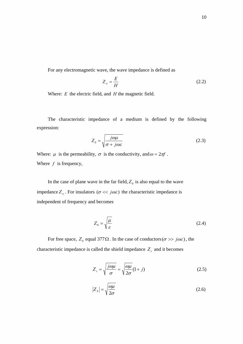
For any electromagnetic wave, the wave impedance is defined as
HEZ w = (2.2)
Where: E the electric field, and H the magnetic field.
The characteristic impedance of a medium is defined by the following
expression:
ωεσ
ωμj
jZ+
=0 (2.3)
Where: μ is the permeability, σ is the conductivity, and fπω 2= .
Where is frequency, f
In the case of plane wave in the far field, is also equal to the wave
impedance . For insulators
0Z
wZ )( ωεσ j<< the characteristic impedance is
independent of frequency and becomes
εμ
=0Z (2.4)
For free space, equal 3770Z Ω . In the case of conductors )( ωεσ j>> , the
characteristic impedance is called the shield impedance and it becomes sZ
)1(2
jjZ s +==σωμ
σωμ (2.5)
σωμ2
=SZ (2.6)

11
2.4 Shielding Effectiveness (SE)
The SE can be defined as the ratio of electric or magnetic field in the shielded
region and electro or magnetic field in the absence of shield
⎟⎟⎠
⎞⎜⎜⎝
⎛−=
a
b
EE
SE log20 dB (2.7)
and
⎟⎟⎠
⎞⎜⎜⎝
⎛−=
a
b
HH
SE log20 dB (2.8)
Where electric field in the shielded region, electro field in the absence of
shield, magnetic field in the shielded region, and magnetic field in the
absence of shield.
bE aE
bH aH
The mechanism of electromagnetic (EM) shielding can be described by three
losses. First, The EM wave (incident wave) is propagating in the air to encounter the
metal. Some is reflected as shown in Fig 2.4. So, it is attenuated by reflection, called
“Reflection Loss”. Second, after the first reflection, the attenuated wave will
propagate from air to metal at the left border. Then, it propagates through the metal to
the right border. Some is absorbed in the metal, called “Absorption Loss”, this loss is
depended on the thickness and permeability of the metal.
Third, the EM wave inside the metal (after reflection and absorption) will
encounter the metal at the right border. Some is reflected at this point or internal
reflected, the EM wave is attenuated by internal reflection is called “Re-Reflection
Loss”. The incident wave is much reduced by these losses.

12
Fig. 2.4 Wave propagation through shielding material [21]
In addition, the electrons in a conductor move in response to the applied time-
varying magnetic field. These moving electrons constitute current in the shield. Since
all real conductors have a finite conductivity, energy is lost in the conductor will this
charge flow. This loss reduces the strength of the field.
The total shielding effectiveness of a solid material with no apertures is equal to
the sum of the absorption loss plus the reflection loss plus a correction
factor to account for multiple reflections in thin shields. Total shielding
effectiveness therefore can be written as
)(A )(R
)(B
BRAS ++= ( ) (2.9) dB`

13
2.4.1 Absorption loss
When an electromagnetic wave passes through a medium, its amplitude
decreases exponentially. This decay occurs because currents induced in the shield
produce ohmic losses and heating of the material. Therefore, we can write
δteEE −= 01 (2.10)
and
δteHH −= 01 (2.11)
Where , is the wave intensity at a distance t within the shield. The
distance required for the wave to be attenuated to
)( 11 HE
e1 of its original value is defined
as the skin depth, which is equal to
ωμσ
δ 2= (2.12)
The absorption loss through a shield can now be written as
δt
eHH
A log20log201
0 == (2.13)
)log(20 etA ⎟⎠⎞
⎜⎝⎛=δ
dB (2.14)
⎟⎠⎞
⎜⎝⎛=δtA 69.8 dB (2.15)
Substituting Equation (2.12) into Equation (2.15) gives the following general
expression for absorption loss:
rrftA σμ34.3= (2.16) dB
In this equation, t is equal the thickness of the shield in inches.
14
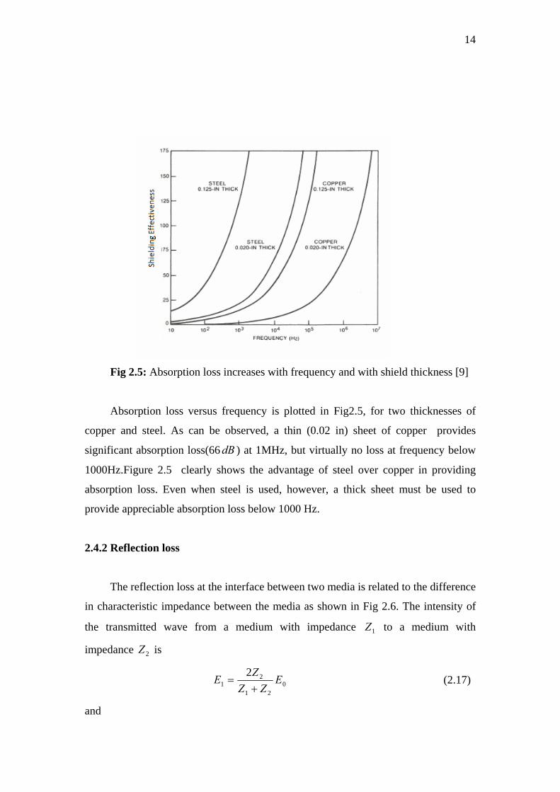
Fig 2.5: Absorption loss increases with frequency and with shield thickness [9]
Absorption loss versus frequency is plotted in Fig2.5, for two thicknesses of
copper and steel. As can be observed, a thin (0.02 in) sheet of copper provides
significant absorption loss(66 ) at 1MHz, but virtually no loss at frequency below
1000Hz.Figure 2.5 clearly shows the advantage of steel over copper in providing
absorption loss. Even when steel is used, however, a thick sheet must be used to
provide appreciable absorption loss below 1000 Hz.
dB
2.4.2 Reflection loss
The reflection loss at the interface between two media is related to the difference
in characteristic impedance between the media as shown in Fig 2.6. The intensity of
the transmitted wave from a medium with impedance to a medium with
impedance is
1Z
2Z
021
21
2 EZZ
ZE+
= (2.17)
and
15
021
11
2 HZZ
ZH+
= (2.18)
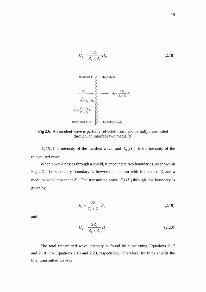
Fig 2.6: An incident wave is partially reflected from, and partially transmitted
through, an interface two media [9]
)( 00 HE is intensity of the incident wave, and is the intensity of the
transmitted wave.
)( 11 HE
When a wave passes through a shield, it encounters two boundaries, as shown in
Fig 2.7. The secondary boundary is between a medium with impedance and a
medium with impedance . The transmitted wave through this boundary is
given by
2Z
1Z )( 11 HE
121
12 EZZ
ZEt += (2.19)
and
121
22 HZZ
ZH t += (2.20)
The total transmitted wave intensity is found by substituting Equations 2.17
and 2.18 into Equations 2.19 and 2.20, respectively. Therefore, for thick shields the
total transmitted wave is
16
0221
21
)(4 E
ZZZZEt +
= (2.21)
0221
21
)(4 H
ZZZZH t +
= (2.22)
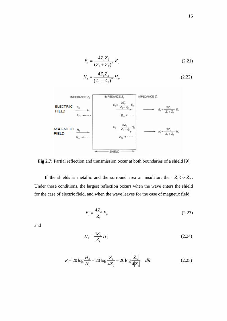
Fig 2.7: Partial reflection and transmission occur at both boundaries of a shield [9]
If the shields is metallic and the surround area an insulator, then .
Under these conditions, the largest reflection occurs when the wave enters the shield
for the case of electric field, and when the wave leaves for the case of magnetic field.
21 ZZ >>
01
24 EZZEt = (2.23)
and
01
24 HZZHt = (2.24)
s
w
ZZ
ZZ
HHR
4log20
4log20log20
2
1
1
0 === (2.25) dB
17
Where
=wZ Impedance of wave prior to entering the shield,
=sZ Impedance of shield
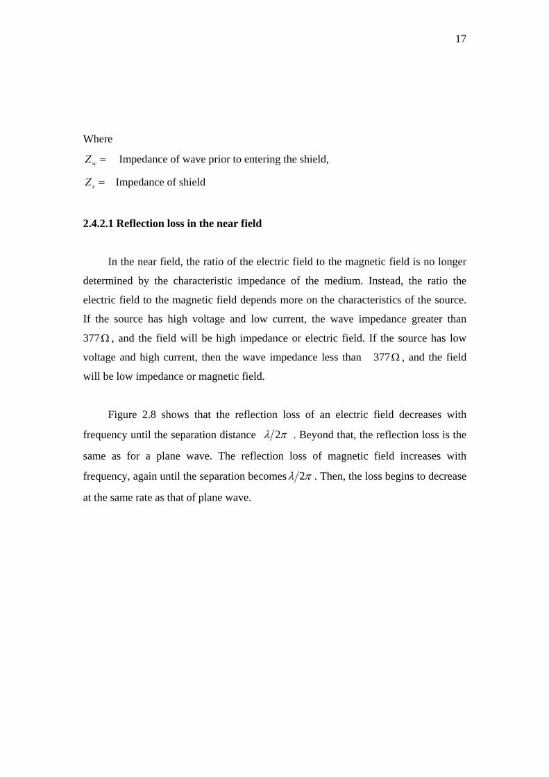
2.4.2.1 Reflection loss in the near field
In the near field, the ratio of the electric field to the magnetic field is no longer
determined by the characteristic impedance of the medium. Instead, the ratio the
electric field to the magnetic field depends more on the characteristics of the source.
If the source has high voltage and low current, the wave impedance greater than
377Ω , and the field will be high impedance or electric field. If the source has low
voltage and high current, then the wave impedance less than 377 , and the field
will be low impedance or magnetic field.
Ω
Figure 2.8 shows that the reflection loss of an electric field decreases with
frequency until the separation distance πλ 2 . Beyond that, the reflection loss is the
same as for a plane wave. The reflection loss of magnetic field increases with
frequency, again until the separation becomes πλ 2 . Then, the loss begins to decrease
at the same rate as that of plane wave.

18
Fig 2.8: Reflection loss in a copper shield varies with frequency, distance from the
source, and type of wave [9]
2.4.3 Multiple reflections in thin shields
If the shield is thin, the reflected wave from the second boundary is re-reflected
off the first boundary, and then it returns to the second boundary to be reflected again,
as shown in Fig 2.9. This can be neglected in the case of a thick shield, because the
absorption loss is high. By the time the wave reaches the second boundary for the
second time, it is of negligible amplitude, because by then it has passed through the
thickness of the shield three times.
For electric fields, most of the incident wave is reflected at the first boundary,
and only a small percentage enters the shield. Therefore, multiple reflections within
the shield can be neglected for electric fields.
19
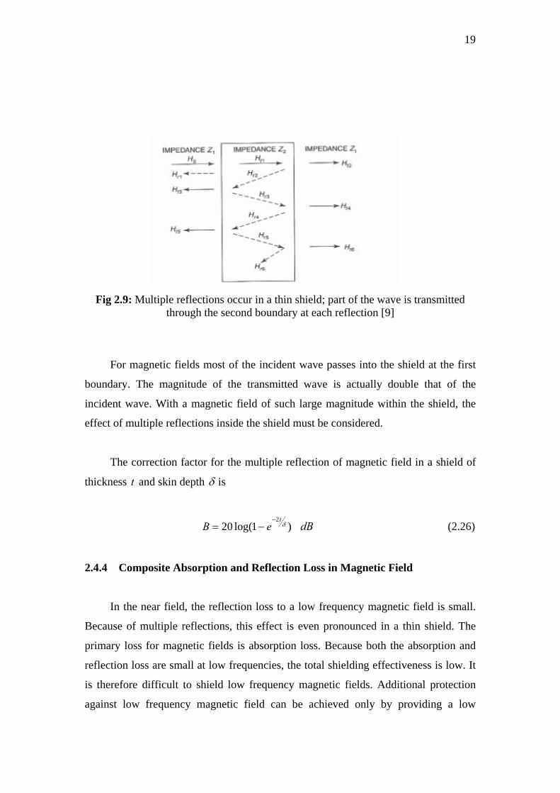
Fig 2.9: Multiple reflections occur in a thin shield; part of the wave is transmitted
through the second boundary at each reflection [9]
For magnetic fields most of the incident wave passes into the shield at the first
boundary. The magnitude of the transmitted wave is actually double that of the
incident wave. With a magnetic field of such large magnitude within the shield, the
effect of multiple reflections inside the shield must be considered.
The correction factor for the multiple reflection of magnetic field in a shield of
thickness and skin depth t δ is
)1log(202δ
teB−
−= (2.26) dB
2.4.4 Composite Absorption and Reflection Loss in Magnetic Field
In the near field, the reflection loss to a low frequency magnetic field is small.
Because of multiple reflections, this effect is even pronounced in a thin shield. The
primary loss for magnetic fields is absorption loss. Because both the absorption and
reflection loss are small at low frequencies, the total shielding effectiveness is low. It
is therefore difficult to shield low frequency magnetic fields. Additional protection
against low frequency magnetic field can be achieved only by providing a low

20
reluctance magnetic shunt path to divert the field around the circuit being protected.
This approach is shown in Fig 2.10.
Fig 2.10: Magnetic material used as a shield by providing a low-reluctance for the magnetic field, diverting it around the shielded region [9]
2.5 Wire Mesh Properties
The number of human beings has to work or reside in places where EMI is
considerable. So they suffer physically or psychologically. Hence EMI-shield has
become a necessity.
For example Copper may be used to reflect electric field and mu-metal may be
taken to absorb magnetic field. But the piece of mu-metal must be thick. This makes
the apron weightier. So there should be optimization between the weight of shield and
the magnetic field to cancel by the electromagnetic shield.
A wire mesh is often used to provide shielding in place of a solid metal sheet. A
mesh is cheaper, lighter, and also allows for air flow – which is particularly important
21
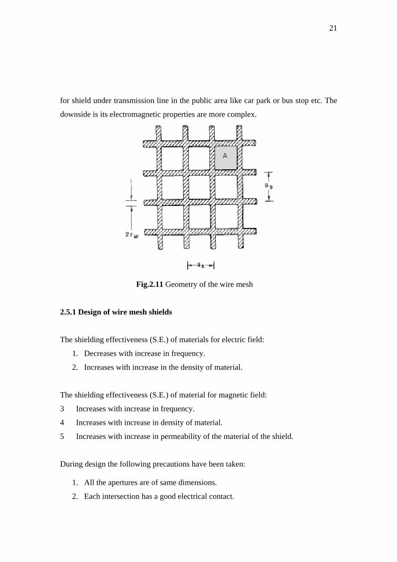
for shield under transmission line in the public area like car park or bus stop etc. The
downside is its electromagnetic properties are more complex.
Fig.2.11 Geometry of the wire mesh
2.5.1 Design of wire mesh shields
The shielding effectiveness (S.E.) of materials for electric field:
1. Decreases with increase in frequency.
2. Increases with increase in the density of material.
The shielding effectiveness (S.E.) of material for magnetic field:
3 Increases with increase in frequency.
4 Increases with increase in density of material.
5 Increases with increase in permeability of the material of the shield.
During design the following precautions have been taken:
1. All the apertures are of same dimensions.
2. Each intersection has a good electrical contact.

22
2.5.2 The size of apertures
In order to be effective, a size of aperture must be as tight as possible. Figures
2.12 and 2.13 illustrate how a magnetic and an electric field, respectively, will pass
through a hole.
Fig 2.12 An H-field which is predominantly
Tangential close to a metallic screen
Fig 2.13 An E-field which will hit a metallic
Screen at right angles
Multiple small apertures will provide better protection than a single large one.
In such cases, the field will not be able to penetrate very long if the diameter is small
compared to the wavelength.

23
Fig 2.14 Multiple small openings are preferable
To a single large one
2.6 Shielding material
The choice of the most effective shielding material depends on frequency. At
low frequency, high permeability magnetic materials are most effective. Mild steel
one of several high permeability magnetic shielding materials 2.6.1 Mild Steel
Mild steel is a type of steel alloy that contains a high amount of carbon as a
major constituent. An alloy is a mixture of metals and non-metals, designed to have
specific properties. Steel is any alloy of iron, consisting of 0.2% to 2.1% of carbon, as
a hardening agent. Besides carbon, there are many metal elements that are a part of
steel alloys. The elements other than iron and carbon, used in steel are chromium,
manganese, tungsten and vanadium.
2.5.1.1 Mild Steel Properties • A high amount of carbon makes mild steel different from other types of steel.
Carbon makes mild steel stronger and stiffer than other type of steel. However, the
hardness comes at the price of a decrease in the ductility of this alloy. Carbon atoms
get affixed in the interstitial sites of the iron lattice and make it stronger.

24
• It has ferromagnetic properties, which make it ideal for manufacture of
electrical devices and motors.
• Mild steel is the cheapest and most versatile form of steel and serves every
application which requires a bulk amount of steel.
2.7 Shielding effectiveness of wire mesh shield
At low frequency the shielding effectiveness of wire mesh for magnetic field
can be derived from the transfer function
shieldofabsencetheinfieldmagnetic
regionshieldtheinfieldmagneticjTm ⋅⋅⋅⋅⋅⋅⋅⋅⋅⋅⋅
=)( ω (2.27)
Considering a plane wave, Equation 2.27 can be written as [4]
1
01)(−
⎟⎟⎠
⎞⎜⎜⎝
⎛+=
sm nZ
jjT ωμω (2.28)
Where:
n = 1 for the parallel-mesh geometry
n = 2 for the cylindrical geometry;
n = 3 for the spherical geometry.
In the case, we can consider the parallel-mesh geometry.
It is clear that the quantity a/n is simply the volume-to-surface ratio ⎟⎟⎠
⎞⎜⎜⎝
⎛=
e
e
SV
a ,
therefore, (2.28) becomes:
1
01)(−
⎟⎟⎠
⎞⎜⎜⎝
⎛+=
es
em SZ
VjjT ωμω (2.29)

53
REFERENCES
[1] Kenneth L. Kaiser,“ Electromagnetic shielding”, 2006.
[2] H. A. Mendez, "Shielding theory of enclosures with apertures,” IEEE Transactions on Electromagnetic Compatibility, vol. 20, pp. 296-305, May 1978.
[3] M. P. Robinson, T. M. Benson, and C. Christopoulos, “Analytical formulation for the shielding effectiveness of enclosures with apertures,” ,” IEEE Transactions on Electromagnetic Compatibility, vol. 40, no. 3, pp. 240–248, Aug. 1998.
[4] K. F. Casey, “Electromagnetic Shielding behavior of wire-mesh Screens,” IEEE Transactions on Electromagnetic Compatibility, vol. 30, No 3. pp. 298-306, August 1988.
[5] O. Losito, Member, IEEE, D. Barletta, and V. Dimiccoli,” A Wide-frequency model of metal foam for shielding applications,”,” IEEE Transaction on Electromagnetic Compatibility, vol. 52, NO. 1, February 2010.
[6] P. Sewell, J. D. Turner, M. P. Robinson, and D. W. P. Thomas, “Comparison of analytic, and approximate models for shielding effectiveness with measurement,” in IEEE Proc.- Sci. Meas. Technol., vol. 145, Mar. 1998, pp. 61–66.
[7] S. $eker, F. Can, O. Cerezci,” Theoretical and experimental study of EM fields and shielding effectiveness due to high voltage transmission lines”, 2001 Proceedings of the 23rd Annual EMBS International Conference, October 25-28, Istanbul, Turkey
[8] Robinson, M.P. et al., “Shielding effectiveness of a rectangular enclosure with a rectangular aperture,” Electronics Letters, Vo1.32, No.17, August 1996, pp1559-1560. [9] HENRY W. OTT,“ Electromagnetic Compatibility Engineering”, 2009.
[10] A. Keshtkar, A. Maghoul, A. Kalantarnia , “Simulation of Shielding Effectiveness in Low Frequencies for Conductive Enclosure,” 2009 Second International Conference on Computer and Electrical Engineering.
54
[11] S.Kim, Joon. Soh,“Magnetic shielding performance of thin metal sheets near power cables,” IEEE Trans. Electromagn. Compat, vol. 46, NO. 2, FEBRUARY 2010. [12]Hassan M. Elkamchouchi, Mohammed A. Ismaeil,“ Shielding Effectiveness of Multi-layered Cylindrical and Spherical Magnetic Shells for Static Fields,” 26th NATIONAL RADIO SCIENCE CONFERENCE (NRSC2009). [13] S.-K. Lee, M. V. Romalis,“ Calculation of magnetic field noise from high-permeability magnetic shields and conducting objects with simple geometry,” JOURNAL OF APPLIED PHYSICS 103, 084904 _2008. [14] D.A. Weston, K McDougall,“ An explanation for the “magic” low frequency magnetic field shielding effectiveness of thin conductive foil with a relative permeability of 1,” (magicSE.R&D.doc) 31-7-2006. [15] HORACIO A. MINDEZ,“ Shielding Theory of Enclosures with Apertures,” IEEE Trans. Electromagn. Compat, vol. EMC-20, NO. 2, MAY 1978. [16] O. Losito,“ An Analytical Characterizzation of Metal Foams for Shielding Applications,” PIERS ONLINE, VOL. 4, NO. 8, 2008. [17] Christopher L. Gardner,“ The Penetration of EM Waves Through Loaded Apertures,” IEEE Trans. Electromagn. Compat, VOL. 37, NO. 3, AUGUST 1995. [18] Karim Wassef, Vasundara V. Varadan, and Vijay K. Varadan,“ Magnetic Field Shielding Concepts for Power Transmission Lines,” IEEE Trans Electromagn. Compat, VOL. 34, NO. 3, MAY 1998. [19] J. Liu, W. Ruan,“ Electromagnetic Fields Near High Voltage Electrical Power Lines: A Parametric Analysis,” IEEE Safe Engineering Services & technologies ltd. [20] CLAYTON R.PAUL,“ Electromagnetic Compatibility”, 2006.
[21] T. Dumrongkittigule, P. Khamphakdi. W. Khan-ngern,“ The Study of Low Frequency Magnetic Field Shielding Causing by Power Transformer,” Department of Electrical Engineering, KMITL, Bangkok, 10520, Thailand.


