Download - SG30/50/110CX Inverters - Sungrow
TD_202006_Logger1000_Quick Guide for SG30-50-110CX Inverters_V1.4 Page 1 of 13
© SUNGROW AUSTRALIA GROUP PTY LTD All rights reserved. As we continuously improving our products, changes to this document may occur without notice.
Logger1000 Commissioning Quick Guide
(SG30/50/110CX Inverters)
Disclaimer
The material in this document has been prepared by Sungrow Australia Group Pty. Ltd. ABN 76
168 258 679 and is intended as a guideline to assist solar installers for troubleshooting. It is not a
statement or advice on any of the Electrical or Solar Industry standards or guidelines. Please
observe all OH&S regulations when working on Sungrow equipment.
This quick guide is to be read in conjunction with the Sungrow’s User Manuals and
SG30/50/110CX inverters as example for demonstration.
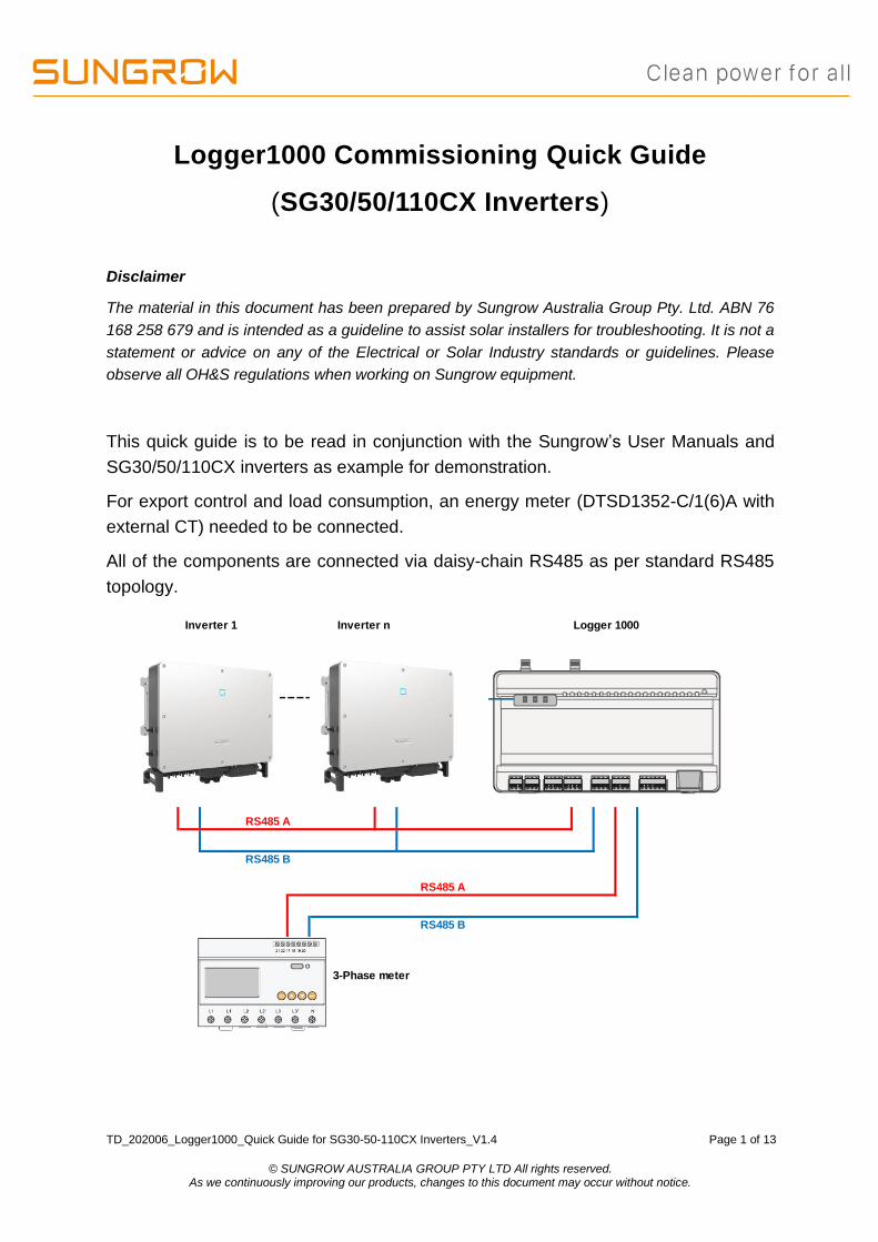
For export control and load consumption, an energy meter (DTSD1352-C/1(6)A with
external CT) needed to be connected.
All of the components are connected via daisy-chain RS485 as per standard RS485
topology.
Logger 1000
RS485 A
RS485 B
RS485 A
RS485 B
3-Phase meter
Inverter 1 Inverter n
TD_202006_Logger1000_Quick Guide for SG30-50-110CX Inverters_V1.4 Page 2 of 13
© SUNGROW AUSTRALIA GROUP PTY LTD All rights reserved. As we continuously improving our products, changes to this document may occur without notice.
Please use the following checklist for quick commissioning:
Procedures Yes/No
RS485
connection
RS485 communication cables installed correctly between
inverters to Logger1000 by terminal blocks?
RS485 communication cables installed correctly between
energy meter DTSD1352-C/1(6)A to Logger1000 by
terminal blocks?
Logger1000
web portal
setup
Logger1000 Setup via WLAN (11.11.11.1; password:
pw1111)
Set the local time
Auto search inverters
Add the energy meter and adjust CT Transformation Ratio
Set up export control if required
Setup Online
Monitoring
Create a solar plant via iSolarCloud APP via an installer
account
Remote
maintenance
Enable International Server
Update iSolarCloud serve domain
Check Port Parameter for IP address
Quick toturial
Part 1 Logger1000 Overview (click here)
Part 2 Logger1000 Commissioning Setup (click here)
Part 3 Logger1000 iSolarCloud Setup (click here)
TD_202006_Logger1000_Quick Guide for SG30-50-110CX Inverters_V1.4 Page 3 of 13
© SUNGROW AUSTRALIA GROUP PTY LTD All rights reserved. As we continuously improving our products, changes to this document may occur without notice.
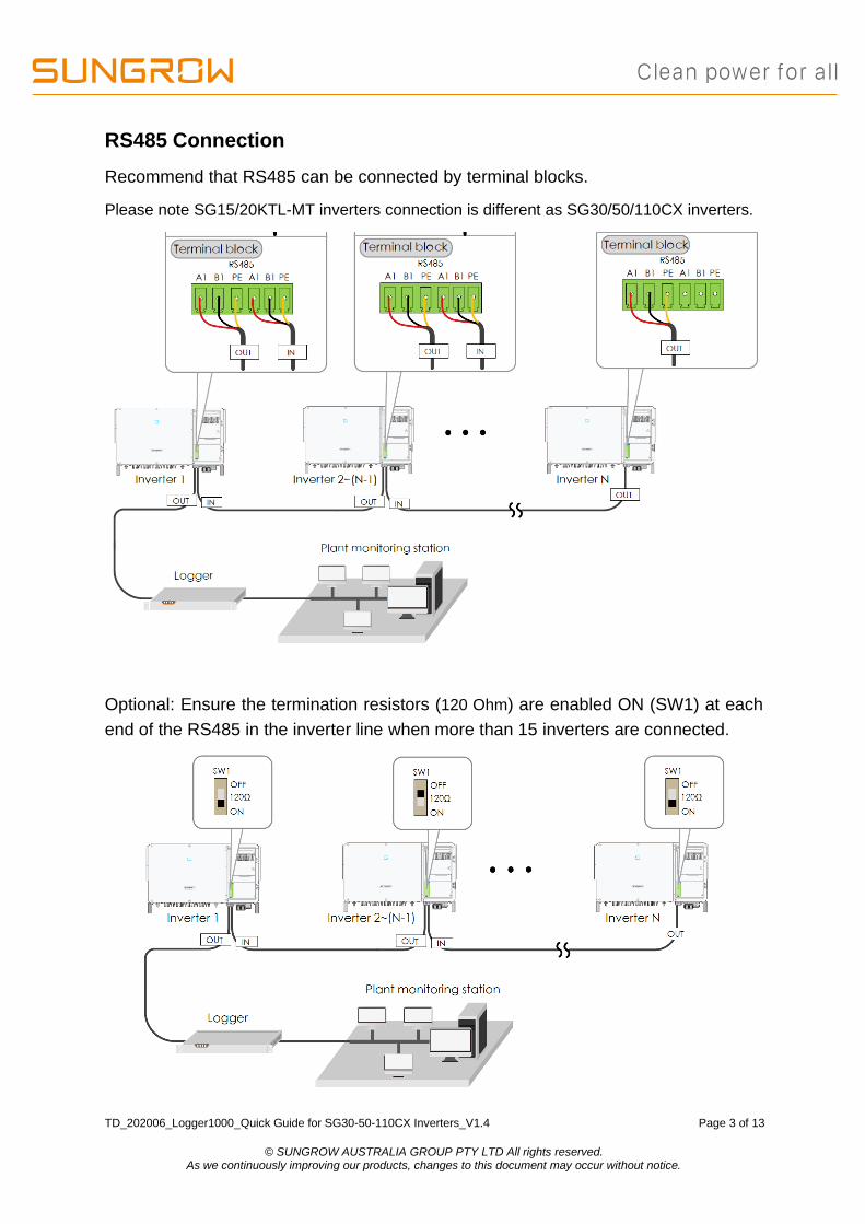
RS485 Connection
Recommend that RS485 can be connected by terminal blocks.
Please note SG15/20KTL-MT inverters connection is different as SG30/50/110CX inverters.
Optional: Ensure the termination resistors (120 Ohm) are enabled ON (SW1) at each
end of the RS485 in the inverter line when more than 15 inverters are connected.

TD_202006_Logger1000_Quick Guide for SG30-50-110CX Inverters_V1.4 Page 4 of 13
© SUNGROW AUSTRALIA GROUP PTY LTD All rights reserved. As we continuously improving our products, changes to this document may occur without notice.
Energy Meter Connection
The site electrician will need to calculate the CT ratio required as per the installation.
The CT ratios can be set by accessing the DTSD1352 energy meter. Please refer
Meter Selection Guide for reference.
Default Modbus address is 1 and the secondary current of CT should be 5A.
The corresponding pinouts to RJ45 are Pin 3 (White-green) to RS485- B and Pin 6
(Green) to RS485+ A:
Terminal 21 to Green cable (RS485+ A) and terminal 22 to White-green cable
(RS485- B) on the DTSD1352 energy meter side. The following figures shows the
meter cable connection on the eneryg meter side.
Connect to Logger1000 via the RS485 cable from the energy meter on RS485 port
A2 and B2 if it has not been used.
TD_202006_Logger1000_Quick Guide for SG30-50-110CX Inverters_V1.4 Page 5 of 13
© SUNGROW AUSTRALIA GROUP PTY LTD All rights reserved. As we continuously improving our products, changes to this document may occur without notice.
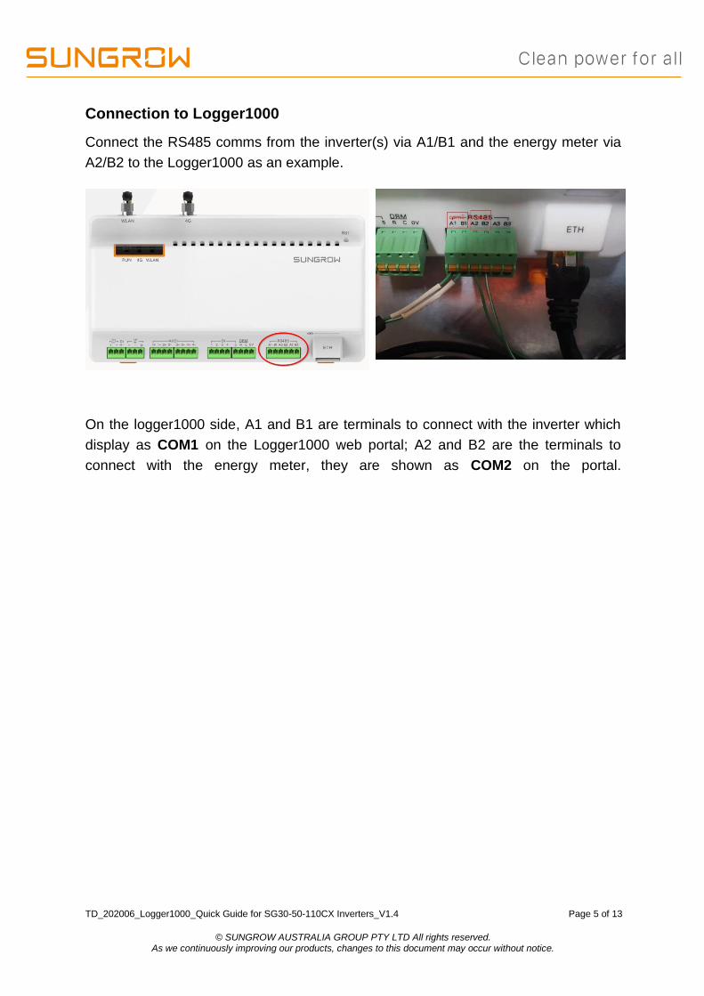
Connection to Logger1000
Connect the RS485 comms from the inverter(s) via A1/B1 and the energy meter via
A2/B2 to the Logger1000 as an example.
On the logger1000 side, A1 and B1 are terminals to connect with the inverter which
display as COM1 on the Logger1000 web portal; A2 and B2 are the terminals to
connect with the energy meter, they are shown as COM2 on the portal.
TD_202006_Logger1000_Quick Guide for SG30-50-110CX Inverters_V1.4 Page 6 of 13
© SUNGROW AUSTRALIA GROUP PTY LTD All rights reserved. As we continuously improving our products, changes to this document may occur without notice.
Logger1000 web portal setup
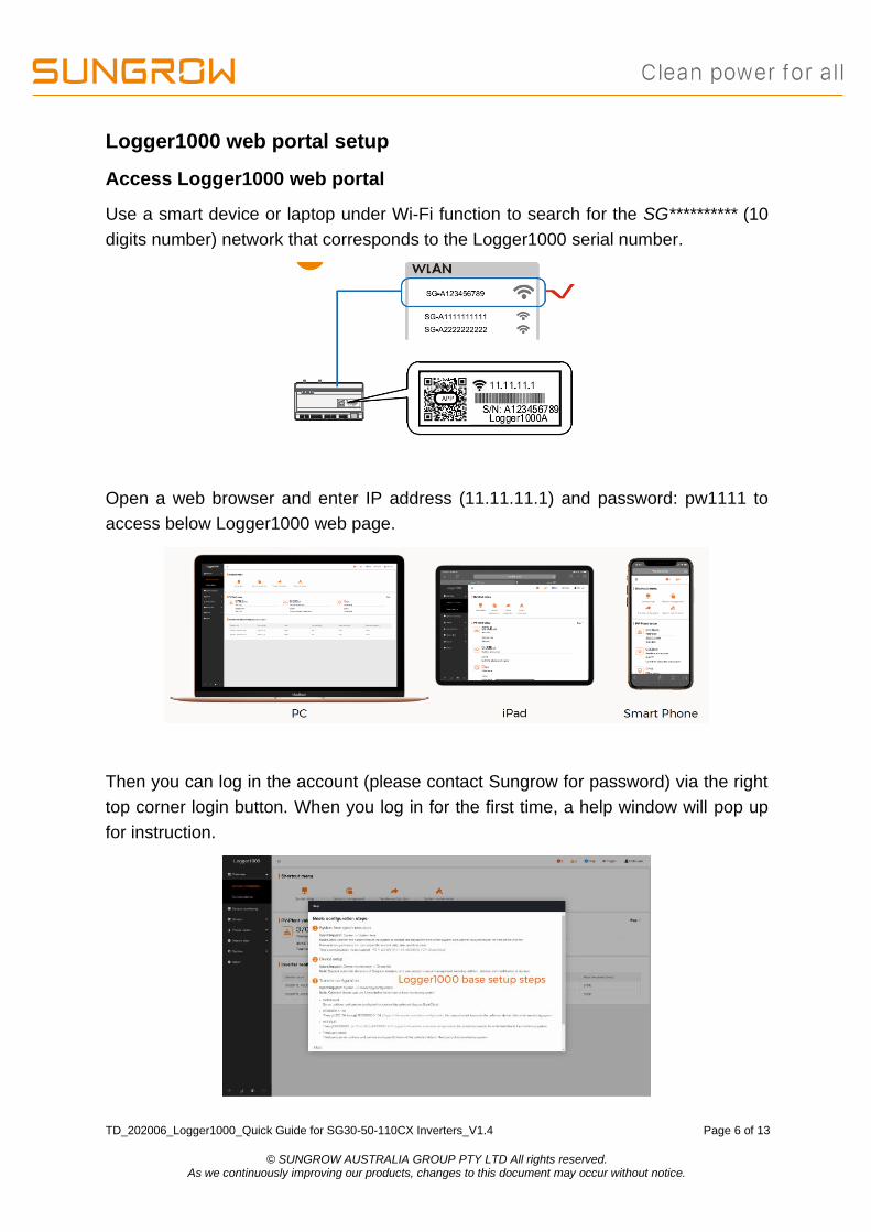
Access Logger1000 web portal
Use a smart device or laptop under Wi-Fi function to search for the SG********** (10
digits number) network that corresponds to the Logger1000 serial number.
Open a web browser and enter IP address (11.11.11.1) and password: pw1111 to
access below Logger1000 web page.
Then you can log in the account (please contact Sungrow for password) via the right
top corner login button. When you log in for the first time, a help window will pop up
for instruction.

TD_202006_Logger1000_Quick Guide for SG30-50-110CX Inverters_V1.4 Page 7 of 13
© SUNGROW AUSTRALIA GROUP PTY LTD All rights reserved. As we continuously improving our products, changes to this document may occur without notice.
Set local time
Navigate to ‘System Time’ under System and select Clock Source to ‘NTP’ and Time
Zone to ‘UTC+10:00’ and make sure to Save
Auto search inverters
Navigate to ‘Device’ and click ‘Device List’ section and click ‘Auto search’.
Sungrow’s inverters will be automatically detected as long as they are correctly
connected and energised.
Confirm the communication status for each device under Communication status
section. Green icon indicates the connection works and red icon means no
connection between Logger1000 and other device.

TD_202006_Logger1000_Quick Guide for SG30-50-110CX Inverters_V1.4 Page 8 of 13
© SUNGROW AUSTRALIA GROUP PTY LTD All rights reserved. As we continuously improving our products, changes to this document may occur without notice.
Add Energy Meter
The energy meter needs to be manually added which is same as any other 3rd party
equipment.
To add the energy meter, click ‘Add device’ and select a device type in the pop-up
window and fill in the required information (Add device for DTSD1352 energy meter
and device address: 254)
If the meter connected with A2 and B2 on the Logger1000, we need to make sure
the port number on the portal is COM2. Otherwise, DTSD1352 meter’s status will
show disconnect.
Add CT Transformation Ratio.
Navigate to ‘Device Monitoring’ and select DTSD1352. If the ratio is 200/5, then
enter value 40.
TD_202006_Logger1000_Quick Guide for SG30-50-110CX Inverters_V1.4 Page 9 of 13
© SUNGROW AUSTRALIA GROUP PTY LTD All rights reserved. As we continuously improving our products, changes to this document may occur without notice.
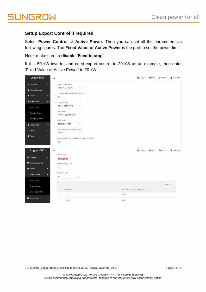
Setup Export Control if required
Select Power Control -> Active Power. Then you can set all the parameters as
following figures. The Fixed Value of Active Power is the part to set the power limit.
Note: make sure to disable ‘Feed-in stop’
If it is 50 kW inverter and need export control to 20 kW as an example, then enter
‘Fixed Value of Active Power’ to 20 kW.
Disable
TD_202006_Logger1000_Quick Guide for SG30-50-110CX Inverters_V1.4 Page 10 of 13
© SUNGROW AUSTRALIA GROUP PTY LTD All rights reserved. As we continuously improving our products, changes to this document may occur without notice.
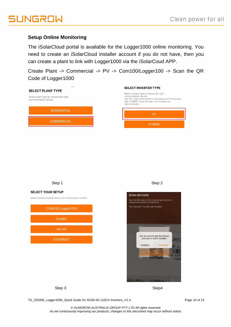
Setup Online Monitoring
The iSolarCloud portal is available for the Logger1000 online monitoring. You
need to create an iSolarCloud installer account if you do not have, then you
can create a plant to link with Logger1000 via the iSolarCoud APP.
Create Plant -> Commercial -> PV -> Com100/Logger100 -> Scan the QR
Code of Logger1000
Step 1 Step 2
Step 3 Step4

TD_202006_Logger1000_Quick Guide for SG30-50-110CX Inverters_V1.4 Page 11 of 13
© SUNGROW AUSTRALIA GROUP PTY LTD All rights reserved. As we continuously improving our products, changes to this document may occur without notice.
Then you only need to enter the customer’s basic information, and the plant
will be created in a few minutes.
After you connect the Logger1000 with the customer’s router via the ethernet
cable, you also need to adjust parameter settings on the Logger1000 via
WLAN.
Use a smart device or laptop under Wi-Fi function to search for the SG********** (10
digits number) network that corresponds to the Logger1000 serial number.
Open a web browser again and enter IP address (11.11.11.1) and password:
pw1111 to access below Logger1000 web page.
Select System-> Remote maintenance, enable the function and make sure
the Remote Service Address is selected as International Server

TD_202006_Logger1000_Quick Guide for SG30-50-110CX Inverters_V1.4 Page 12 of 13
© SUNGROW AUSTRALIA GROUP PTY LTD All rights reserved. As we continuously improving our products, changes to this document may occur without notice.
Then go to System-> Transfer Configuration, click the Setting gearwheel
highlighted in red to change the Server Domain. Please make sure the domain
address is api.isolarcloud.com.hk
After this, Select Port Parameter-> Ethernet. Select ON for the DHCP setting
and the home router could allocate a random IP address to Logger1000.
TD_202006_Logger1000_Quick Guide for SG30-50-110CX Inverters_V1.4 Page 13 of 13
© SUNGROW AUSTRALIA GROUP PTY LTD All rights reserved. As we continuously improving our products, changes to this document may occur without notice.
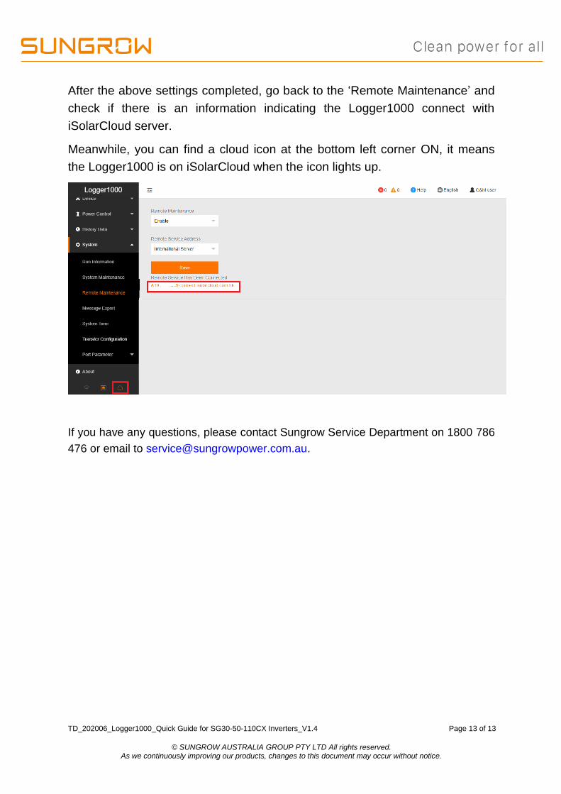
After the above settings completed, go back to the ‘Remote Maintenance’ and
check if there is an information indicating the Logger1000 connect with
iSolarCloud server.
Meanwhile, you can find a cloud icon at the bottom left corner ON, it means
the Logger1000 is on iSolarCloud when the icon lights up.
If you have any questions, please contact Sungrow Service Department on 1800 786
476 or email to [email protected].


