
Application ReportSPRABP9–October 2013
Sensorless Field Oriented Control of 3-Phase InductionMotors
ManishBhardwaj
ABSTRACTThis application report presents a solution to control an AC induction motor using the TMS320F2803xmicrocontrollers. TMS320F2803x devices are part of the family of C2000™ microcontrollers which enablecost-effective design of intelligent controllers for three phase motors by reducing the system componentsand increase efficiency. With these devices it is possible to realize far more precise digital vector controlalgorithms like the field orientated control (FOC). This algorithm’s implementation is discussed in thisdocument. The FOC algorithm maintains efficiency in a wide range of speeds and takes into considerationtorque changes with transient phases by processing a dynamic model of the motor. Among the solutionsproposed are ways to eliminate the phase current sensors and use an observer for speed sensorlesscontrol.
This application report covers the following:• A theoretical background on field oriented motor control principle.• Incremental build levels based on modular software blocks• Experimental results
Contents1 Introduction .................................................................................................................. 32 Induction Motors ............................................................................................................ 43 Field Oriented Control ...................................................................................................... 64 Benefits of 32-Bit C2000 Controllers for Digital Motor Control (DMC) ............................................. 135 TI Literature and Digital Motor Control (DMC) Library ................................................................ 146 Hardware Configuration (HVDMC R1.1 Kit) ........................................................................... 187 Incremental System Build for ACI Sensorless Project ................................................................ 228 References ................................................................................................................. 45
List of Figures
1 Induction Motor Rotor ...................................................................................................... 42 Squirrel Cage Rotor AC Induction Motor Cutaway View............................................................... 53 Separated Excitation DC Motor Model ................................................................................... 64 Stator Current Space Vector and Its Component in (a,b,c) ........................................................... 85 Stator Current Space Vector and Its Component in the Stationary Reference Frame ............................ 86 Stator Current Space Vector and Its Component in (α, β) and in the d,q Rotating Reference Frame .......... 97 Basic Scheme of FOC for ACI Motor ................................................................................... 108 Current, Voltage and Rotor Flux Space Vectors in the d,q Rotating Reference Frame and Their
Relationship With a,b,c and (α, β) Stationary Reference Frame .................................................... 119 Overall Block Diagram of Indirect Rotor Flux Oriented Control ..................................................... 1210 A 3-ph Induction Motor Drive Implementation ......................................................................... 1611 Software Flow .............................................................................................................. 17
C2000, Code Composer Studio are trademarks of Texas Instruments.Windows is a registered trademark of Microsoft Corporation.All other trademarks are the property of their respective owners.
1SPRABP9–October 2013 Sensorless Field Oriented Control of 3-Phase Induction MotorsSubmit Documentation Feedback
Copyright © 2013, Texas Instruments Incorporated

www.ti.com
12 Using AC Power to Generate DC Bus Power ......................................................................... 1913 Using External DC Power Supply to Generate DC-Bus for the Inverter ........................................... 2014 Watch Window Variables ................................................................................................. 2115 SVGEN Duty Cycle Outputs Ta, Tb, Tc and Tb-Tc ................................................................... 2316 DAC-1-4 Outputs Showing Ta, Tb, Tc and Tb-Tc Waveforms ...................................................... 2417 Level 1 — Incremental System Build Block Diagram................................................................. 2618 Calculated Phase A and B Voltages By Volt1 Module, rg1.Out, and svgen_dq1.Ta ............................. 2719 The Waveforms of Phase A Voltage and Current and Phase B Voltage and Current ........................... 2820 Amplified Phase A Current ............................................................................................... 2921 Level 2 — Incremental System Build Block Diagram................................................................. 3022 Svgen_dq1.Ta, Phase A Voltage, and Phase A and B Current Waveforms ...................................... 3223 Level 3 — Incremental System Build Block Diagram................................................................. 3424 Estimated d and q Fluxes With Estimated Theta and Phase A Current Waveform .............................. 3525 Level 4 — Incremental System Build Block Diagram................................................................. 3626 Level 5A — Incremental System Build Block Diagram ............................................................... 3927 Level 5B — Incremental System Build Block Diagram ............................................................... 4028 Phase A and B Current With Estimated Theta and Phase A Voltage Waveforms ............................... 4229 Flux and Torque Components of the Stator Current in the Synchronous Reference Frame.................... 4230 Level 6A — Incremental System Build Block Diagram ............................................................... 4331 Level 6B — Incremental System Build Block Diagram ............................................................... 44
List of Tables
1 Testing Modules in Each Incremental System Build ................................................................. 22
2 Sensorless Field Oriented Control of 3-Phase Induction Motors SPRABP9–October 2013Submit Documentation Feedback
Copyright © 2013, Texas Instruments Incorporated

www.ti.com Introduction
1 IntroductionThe motor control industry is a strong, aggressive sector. To remain competitive new products mustaddress several design constraints including cost reduction, power consumption reduction, power factorcorrection, and reduced EMI radiation. In order to meet these challenges advanced control algorithms arenecessary. Embedded control technology allows both a high level of performance and system costreduction to be achieved. According to market analysis, the majority of industrial motor applications useAC induction motors. The reasons for this are higher robustness, higher reliability, lower prices and higherefficiency (up to 80%) on comparison with other motor types. However, the use of induction motors ischallenging because of its complex mathematical model, its non linear behavior during saturation and theelectrical parameter oscillation which depends on the physical influence of the temperature. These factorsmake the control of induction motor complex and call for use of a high performance control algorithmssuch as “vector control” and a powerful microcontroller to execute this algorithm.
During the last few decades the field of controlled electrical drives has undergone rapid expansion duemainly to the benefits of microcontrollers. These technological improvements have enabled thedevelopment of very effective AC drive control with lower power dissipation hardware and more accuratecontrol structures. The electrical drive controls become more accurate in the sense that not only are theDC quantities controlled but also the three phase AC currents and voltages are managed by so-calledvector controls. This document briefly describes the implementation of the most efficient form of a vectorcontrol scheme: the Field Orientated Control (FOC) method. The FOC method is based on three majorpoints:• Machine current and voltage space vectors• The transformation of a three-phase speed- and time-dependent system into a two coordinate time
invariant system• Effective Space Vector Pulse Width Modulation pattern generationThese algorithms allow the control of an AC machine to acquire every advantage of DC machine controland free itself from mechanical commutation drawbacks. Furthermore, this control structure, by achievinga very accurate steady state and transient control, leads to high dynamic performance in terms ofresponse times and power conversion.
3SPRABP9–October 2013 Sensorless Field Oriented Control of 3-Phase Induction MotorsSubmit Documentation Feedback
Copyright © 2013, Texas Instruments Incorporated

Skewed Cage Bars
End Rings
Induction Motors www.ti.com
2 Induction MotorsInduction motors derive their name from the way the rotor magnetic field is created. The rotating statormagnetic field induces currents in the short circuited rotor. These currents produce the rotor magneticfield, which interacts with the stator magnetic field, and produces torque, which is the useful mechanicaloutput of the machine.
The three phase squirrel cage AC induction motor is the most widely used motor. The bars forming theconductors along the rotor axis are connected by a thick metal ring at the ends, resulting in a short circuitas shown in Figure 1. The sinusoidal stator phase currents fed in the stator coils create a magnetic fieldrotating at the speed of the stator frequency (ωs). The changing field induces a current in the cageconductors, which results in the creation of a second magnetic field around the rotor wires. As aconsequence of the forces created by the interaction of these two fields, the rotor experiences a torqueand starts rotating in the direction of the stator field.
Figure 1. Induction Motor Rotor
As the rotor begins to speed up and approach the synchronous speed of the stator magnetic field, therelative speed between the rotor and the stator flux decreases, decreasing the induced voltage in thestator and reducing the energy converted to torque. This causes the torque production to drop off, and themotor will reach a steady state at a point where the load torque is matched with the motor torque. Thispoint is an equilibrium reached depending on the instantaneous loading of the motor. In brief:• Since the induction mechanism needs a relative difference between the motor speed and the stator
flux speed, the induction motor rotates at a frequency near, but less than, that of the synchronousspeed.
• This slip must be present, even when operating in a field-oriented control regime.• The rotor in an induction motor is not externally excited. This means that there is no need for slip rings
and brushes. This makes the induction motor robust, inexpensive and need less maintenance.• Torque production is governed by the angle formed between the rotor and the stator magnetic fluxes.
In Figure 2 the rotor speed is denoted by Ω. Stator and rotor frequencies are linked by a parameter calledthe slip s, expressed in per unit as s = (ω2 - ωr) / ωs.
4 Sensorless Field Oriented Control of 3-Phase Induction Motors SPRABP9–October 2013Submit Documentation Feedback
Copyright © 2013, Texas Instruments Incorporated

( )( )
( ) ( ) ( )
: AC supply freq /tator rotating field speed / :
: stator poles pairs number
otor rotating speed / : 1 1
s
s s
s
rad ss sS rad s
ps p
sR rad s s sps
w ì üwï ï· W = × í ý
ï ïî þw
· W = - W = -
Stator flux
A’
A
B
C
C’
B’
ia
Rotor rotation
Rotor flux
Aluminum bar
W
WS
WR
www.ti.com Induction Motors
Figure 2. Squirrel Cage Rotor AC Induction Motor Cutaway View
where s is called the “slip”: it represents the difference between the synchronous frequency and the actualmotor rotating speed.
5SPRABP9–October 2013 Sensorless Field Oriented Control of 3-Phase Induction MotorsSubmit Documentation Feedback
Copyright © 2013, Texas Instruments Incorporated

Armature Circuit
Ue
ie
( )F
Inductor (fieldexcitation)
(E, R)
Tem
UM
T
= K. .
= f(I )
em
e
F
F W
F
= K. .I
E
W
Field Oriented Control www.ti.com
3 Field Oriented Control
3.1 IntroductionA simple control such as the V/Hz strategy has limitations on the performance. To achieve better dynamicperformance, a more complex control scheme needs to be applied, to control the induction motor. With themathematical processing power offered by the microcontrollers, we can implement advanced controlstrategies, which use mathematical transformations in order to decouple the torque generation and themagnetization functions in an AC induction motor. Such decoupled torque and magnetization control iscommonly called rotor flux oriented control, or simply Field Oriented Control (FOC).
3.2 The Main Philosophy Behind the FOCIn order to understand the spirit of the Field Oriented Control technique, let us start with an overview of theseparately excited direct current (DC) Motor. In this type of motor, the excitation for the stator and rotor isindependently controlled. An electrical study of the DC motor shows that the produced torque and the fluxcan be independently tuned. The strength of the field excitation (the magnitude of the field excitationcurrent) sets the value of the flux. The current through the rotor windings determines how much torque isproduced. The commutator on the rotor plays an interesting part in the torque production. The commutatoris in contact with the brushes, and the mechanical construction is designed to switch into the circuit thewindings that are mechanically aligned to produce the maximum torque. This arrangement then meansthat the torque production of the machine is fairly near optimal all the time. The key point here is that thewindings are managed to keep the flux produced by the rotor windings orthogonal to the stator field. Fluxand torque are independently controlled and the current through the rotor windings determines how muchtorque is produced as shown in Figure 3.
Figure 3. Separated Excitation DC Motor Model
Induction machines do not have the same key features as the DC motor. However, in both cases we haveonly one source that can be controlled which is the stator currents. On the synchronous machine, the rotorexcitation is given by the permanent magnets mounted onto the shaft. On the synchronous motor, the onlysource of power and magnetic field is the stator phase voltage. Obviously, as opposed to the DC motor,flux and torque depend on each other.
The goal of the FOC (also called vector control) on synchronous and asynchronous machine is to be ableto separately control the torque producing and magnetizing flux components. The control technique goal isto, in a sense, imitate the DC motor’s operation.
6 Sensorless Field Oriented Control of 3-Phase Induction Motors SPRABP9–October 2013Submit Documentation Feedback
Copyright © 2013, Texas Instruments Incorporated

m iR Sq
¥ Y
www.ti.com Field Oriented Control
3.3 Why Field Oriented ControlAsynchronous machines have some natural limitations with a V/Hz control approach. FOC controlbypasses these limitations by decoupling the effect of the torque and the magnetizing flux. With decoupledcontrol of the magnetization, the torque-producing component of the stator flux can now be thought of asindependent torque control. Now, decoupled control, at low speeds, the magnetization can be maintainedat the proper level, and the torque can be controlled to regulate the speed.
To decouple the torque and flux, you must engage several mathematical transforms, whereinmicrocontrollers add the most value. The processing capability provided by the microcontrollers enablesthese mathematical transformations to be carried out very quickly. This in turn implies that the entirealgorithm controlling the motor can be executed at a fast rate, enabling higher dynamic performance. Inaddition to the decoupling, a dynamic model of the motor is now used for the computation of manyquantities such as rotor flux angle and rotor speed. This means that their effect is accounted for, and theoverall quality of control is better.
3.4 Technical BackgroundThe Field Orientated Control consists of controlling the stator currents represented by a vector. Thiscontrol is based on projections which transform a three phase time and speed dependent system into atwo coordinate (d and q coordinates) time invariant system. These projections lead to a structure similar tothat of a DC machine control. Field orientated controlled machines need two constants as inputreferences: the torque component (aligned with the q coordinate) and the flux component (aligned with dcoordinate). As Field Orientated Control is simply based on projections the control structure handlesinstantaneous electrical quantities. This makes the control accurate in every working operation (steadystate and transient) and independent of the limited bandwidth mathematical model. The FOC thus solvesthe classic scheme problems, in the following ways:• The ease of reaching constant reference (torque component and flux component of the stator current)• The ease of applying direct torque control because in the (d,q) reference frame the expression of the
torque is:
By maintaining the amplitude of the rotor flux (φR) at a fixed value we have a linear relationship betweentorque and torque component (iSq). We can then control the torque by controlling the torque component ofstator current vector.
7SPRABP9–October 2013 Sensorless Field Oriented Control of 3-Phase Induction MotorsSubmit Documentation Feedback
Copyright © 2013, Texas Instruments Incorporated

C
b
a=aiSa
b
iS
iSb
C
ia
a
a
2
ic
aib
b
iS
2
3j
e
P
a =
4
2 3j
e
P
a =
= + a + a2
i i i is a b c
Field Oriented Control www.ti.com
3.5 Space Vector Definition and ProjectionThe three-phase voltages, currents and fluxes of AC-motors can be analyzed in terms of complex spacevectors. With regard to the currents, the space vector can be defined as follows. Assuming that Ia, Ib, Ic arethe instantaneous currents in the stator phases, then the complex stator current vector Is is defined by:
where and , represent the spatial operators.
Figure 4 shows the stator current complex space vector:
Figure 4. Stator Current Space Vector and Its Component in (a,b,c)
where (a,b,c) are the three phase system axes. This current space vector depicts the three phasesinusoidal system but still needs to be transformed into a two time invariant coordinate system. You cansplit this transformation into two steps:• (a,b,c) → (α, β) (the Clarke transformation), which outputs a two coordinate time variant system• (a, β) → (d,q) (the Park transformation), which outputs a two coordinate time invariant system
3.6 The (a,b,c) → (α, β) Projection (Clarke transformation)The space vector can be reported in another reference frame with only two orthogonal axis called (α, β).Assuming that the axis a and the axis α are in the same direction, you have the following vector diagram:
Figure 5. Stator Current Space Vector and Its Component in the Stationary Reference Frame
8 Sensorless Field Oriented Control of 3-Phase Induction Motors SPRABP9–October 2013Submit Documentation Feedback
Copyright © 2013, Texas Instruments Incorporated

cos sin
sin cos
i i isd s s
i i isq s s
= q + qìa bï
ïíï = - q + qï a bî
b
a=aiSa
q
iS
iSb
YR
iSd
d
q
iSr
1 2
3 3
i i
s a
i i i
s a b
=ìaï
ïíï = +ï bî
www.ti.com Field Oriented Control
The projection that modifies the three phase system into the (α, β) two dimension orthogonal system is:
The two phase (α, β) currents still depend on time and speed.
3.7 The (α, β) → (d.q) Projection (Park Transformation)This is the most important transformation in the FOC. In fact, this projection modifies a two phaseorthogonal system (α, β) into the d,q rotating reference frame. If we consider the d axis aligned with therotor flux, Figure 6 shows, for the current vector, the relationship from the two reference frame:
Figure 6. Stator Current Space Vector and Its Component in (α, β) and in the d,q Rotating ReferenceFrame
where θ is the rotor flux position. The flux and torque components of the current vector are determined bythe following equations:
These components depend on the current vector (α, β) components and on the rotor flux position; if weknow the right rotor flux position then, by this projection, the d,q component becomes a constant. Twophase currents now turn into dc quantity (time-invariant). At this point the torque control becomes easierwhere constant Isd (flux component) and Isq (torque component) current components controlledindependently.
9SPRABP9–October 2013 Sensorless Field Oriented Control of 3-Phase Induction MotorsSubmit Documentation Feedback
Copyright © 2013, Texas Instruments Incorporated

q
PI
PI
SVPWM
VDC
VS refa
VS refb
3-phaseInverter
a b,
a b,
d,q
a,b
Clarke Tr.Park Tr.
ACMotor
VSqref
VSdref
Inv. Park Tr.
iSq
iSd
iSa
iSb ib
ia
iSdref
iSqref
d,q
a b,
q
Field Oriented Control www.ti.com
3.8 The Basic Scheme for the FOCFigure 7 summarizes the basic scheme of torque control with FOC:
Figure 7. Basic Scheme of FOC for ACI Motor
Two motor phase currents are measured. These measurements feed the Clarke transformation module.The outputs of this projection are designated isα and isβ. These two components of the current are theinputs of the Park transformation that gives the current in the d,q rotating reference frame. The isd and isqcomponents are compared to the references isdref (the flux reference) and isqref (the torque reference). Atthis point, this control structure shows an interesting advantage: you can control either synchronous orinduction machines by simply changing the flux reference and obtaining rotor flux position. In asynchronous permanent magnet a motor, the rotor flux is fixed (determined by the magnets) and there isno need to create additional flux. Therefore, when controlling a PMSM, isdref should be set to zero. Sinceinduction motors need a rotor flux creation in order to operate, the flux reference must not be zero. Thisconveniently solves one of the major drawbacks of the “classic” control structures: the portability fromasynchronous to synchronous drives.
The torque command isqref could be the output of the speed regulator when we use a speed FOC. Theoutputs of the current regulators are Vsdref and Vsqref. They are applied to the inverse Park transformation.The outputs of this projection are Vsαref and Vsβref, which are the components of the stator vector voltage inthe (α, β) stationary orthogonal reference frame. These are the inputs of the space vector pulse widthmodulation (PWM). The outputs of this block are the signals that drive the inverter. Note that both Parkand inverse Park transformations need the rotor flux position. Obtaining this rotor flux position depends onthe AC machine type (synchronous or asynchronous machine). Rotor flux position considerations aremade in Section 3.9.
10 Sensorless Field Oriented Control of 3-Phase Induction Motors SPRABP9–October 2013Submit Documentation Feedback
Copyright © 2013, Texas Instruments Incorporated

b
a=a
q
iS
YR
d
q
vS
b
c
www.ti.com Field Oriented Control
3.9 Rotor Flux PositionKnowledge of the rotor flux position is the core of the FOC. In fact, if there is an error in this variable therotor flux will not be aligned with d-axis, and isd and isq, flux and torque components of the stator current,will be incorrect. Figure 8 shows the (a,b,c), (α, β) and (d,q) reference frames, and the correct position ofthe rotor flux, the stator current, and stator voltage space vector that rotates with d,q reference atsynchronous speed.
Figure 8. Current, Voltage and Rotor Flux Space Vectors in the d,q Rotating Reference Frame and TheirRelationship With a,b,c and (α, β) Stationary Reference Frame
The measure of the rotor flux position is different if we consider synchronous or induction motor:• In the synchronous machine the rotor speed is equal to the rotor flux speed. Then θ (rotor flux position)
is directly measured by position sensor or by integration of rotor speed.• In the induction machine if the rotor speed is not equal to the rotor flux speed (there is a slip speed),
then the rotor speed needs a particular method to calculate θ. The basic method is to use the currentmodel which needs two equations of the motor model in d,q reference frame.
Theoretically, the field oriented control for an induction motor drive can be mainly categorized into twotypes: indirect and direct schemes. The field to be oriented could be a rotor, stator, or airgap flux linkage.In the indirect field oriented control, the slip estimation with measured or estimated rotor speed is requiredin order to compute the synchronous speed. There is no flux estimation appearing in the system. For thedirect scheme, the synchronous speed is computed basing on the flux angle which is available from fluxestimator or flux sensors (Hall effects). In this implementing system, the direct (rotor) flux oriented controlsystem with flux and open-loop speed estimators is described. The key module of this system is the fluxestimator. The overall block diagram of this project is depicted in Figure 9.
11SPRABP9–October 2013 Sensorless Field Oriented Control of 3-Phase Induction MotorsSubmit Documentation Feedback
Copyright © 2013, Texas Instruments Incorporated

wr*
wr
PIiSqref
iSq
PI
PIiSdref
+ +
iSd VSqref
VSdref
Inv. ParkTrans.
VS refb
VS refa
ParkTrans.
Space-VectorPWM
Generator
PWM1PWM2PWM3PWM4PWM5PWM6
DC SupplyVoltage
VoltageSourceInverter
PWM5PWM1
PWM3
Vdc
iSa
iSbClarkeTrans.
Phase VoltageReconstruction
3-ph InductionMotor
TMS302F2803x
FluxEstimator
Open-Speed
Estimator
qr
lSa
lSb
qr
iSb
qr
iSa
iSa
iSb
VSa
VSb
iSa
iSb
* Reference variable
+
Field Oriented Control www.ti.com
Figure 9. Overall Block Diagram of Indirect Rotor Flux Oriented Control
12 Sensorless Field Oriented Control of 3-Phase Induction Motors SPRABP9–October 2013Submit Documentation Feedback
Copyright © 2013, Texas Instruments Incorporated

www.ti.com Benefits of 32-Bit C2000 Controllers for Digital Motor Control (DMC)
4 Benefits of 32-Bit C2000 Controllers for Digital Motor Control (DMC)The C2000 family of devices posses the desired computation power to execute complex control algorithmsalong with the right mix of peripherals to interface with the various components of the DMC hardware likethe ADC, ePWM, QEP, eCAP, and so forth. These peripherals have all the necessary hooks forimplementing systems which meet safety requirements, like the trip zones for PWMs and comparators.Along with this the C2000 ecosystem of software (libraries and application software) and hardware(application kits) help in reducing the time and effort needed to develop a Digital Motor Control solution.The DMC Library provides configurable blocks that can be reused to implement new control strategies.IQMath Library enables easy migration from floating point algorithms to fixed point thus accelerating thedevelopment cycle.
Therefore, with C2000 family of devices it is easy and quick to implement complex control algorithms(sensored and sensorless) for motor control. C2000 devices and advanced control schemes provide thefollowing system improvements:• Favors system cost reduction by an efficient control in all speed range implying right dimensioning of
power device circuits.• Advanced control algorithms reduce torque ripple, thus resulting in lower vibration and longer life time
of the motor.• Advanced control algorithms reduce harmonics generated by the inverter thus reducing filter cost.• Sensorless algorithms eliminate the need for speed or position sensor.• Fewer look-up tables to reduce the amount of memory required.• Real-time generation of smooth near-optimal reference profiles and move trajectories results in better-
performance.• Generation of high-resolution PWMs is possible using the ePWM peripheral to control the power
switching inverters.• Single chip control system.
For advanced controls, C2000 controllers:• Enable control of multi-variable and complex systems using modern intelligent methods such as neural
networks and fuzzy logic• Perform adaptive control. C2000 controllers have the speed capabilities to concurrently monitor and
control the system. A dynamic control algorithm adapts itself in real time to variations in systembehavior.
• Perform parameter identification for sensorless control algorithms, self commissioning, onlineparameter estimation update
• Perform advanced torque ripple and acoustic noise reduction.• Provide diagnostic monitoring with spectrum analysis. By observing the frequency spectrum of
mechanical vibrations, failure modes can be predicted in early stages.• Produce sharp-cut-off notch filters that eliminate narrow-band mechanical resonance. Notch filters
remove energy that would otherwise excite resonant modes and possibly make the system unstable.
13SPRABP9–October 2013 Sensorless Field Oriented Control of 3-Phase Induction MotorsSubmit Documentation Feedback
Copyright © 2013, Texas Instruments Incorporated

TI Literature and Digital Motor Control (DMC) Library www.ti.com
5 TI Literature and Digital Motor Control (DMC) LibraryLiterature distinguishes two types of FOC control:• Direct FOC control: In this case we try to directly estimate the rotor flux based upon the measurements
of terminal voltages and currents.• Indirect FOC control: In this case the goal is to estimate the slip based upon the motor model in FOC
condition and to recalculate the rotor flux angle from the integration of estimated slip and measuredrotor speeds. Again knowing the motor parameters, especially rotor time constant, is key in order toachieve the FOC control.
This document discusses the indirect FOC control.
The DMC library is composed of functions represented as blocks. These blocks are categorized as:• Transforms and Estimators (Clarke, Park, Sliding Mode Observer, Phase Voltage Calculation, and
Resolver, Flux, and Speed Calculators and Estimators)• Control (Signal Generation, PID, BEMF Commutation, Space Vector Generation)• Peripheral Drivers (PWM abstraction for multiple topologies and techniques, ADC drivers, and motor
sensor interfaces)
Each block is a modular software macro and separately documented with source code, use, and technicaltheory. For the source codes and explanation of macro blocks, install the controlSUITE software fromhttp://www.ti.com/controlsuite. After installing the software, check the following folders for the sourcecodes and explanations for macro blocks:• C:\TI\controlSUITE\libs\app_libs\motor_control\math_blocks\v4.0• C:\TI\controlSUITE\libs\app_libs\motor_control\drivers\f2803x_v2.0
These modules allow users to quickly build, or customize, their own systems. The library supports thethree motor types: ACI, BLDC, PMSM, and comprises both peripheral dependent (software drivers) andtarget dependent modules.
The DMC library components have been used by TI to provide system examples. At initialization all DMCLibrary variables are defined and inter-connected. At run-time the macro functions are called in order.Each system is built using an incremental build approach, which allows some sections of the code to bebuilt at a time, so that the developer can verify each section of their application one step at a time. This iscritical in real-time control applications where so many different variables can affect the system and manydifferent motor parameters need to be tuned.
NOTE: TI DMC modules are written in form of macros for optimization purposes. For more details,see Optimizing Digital Motor Control (DMC) Libraries (SPRAAK2). The macros are defined inthe header files. You can open the respective header file and change the macro definition, ifneeded. In the macro definitions, there should be a backslash ”\” at the end of each line asshown in Example 1, which means that the code continues in the next line. Any characterincluding invisible ones like “space” or “tab” after the backslash will cause compilation error.Therefore, make sure that the backslash is the last character in the line. In terms of codedevelopment, the macros are almost identical to C function, and the user can easily convertthe macro definition to a C functions.
Example 1. A Typical DMC Macro Definition
#define PARK_MACRO(v) \\
v.Ds = _IQmpy(v.Alpha,v.Cosine) + _IQmpy(v.Beta,v.Sine); \v.Qs = _IQmpy(v.Beta,v.Cosine) - _IQmpy(v.Alpha,v.Sine);
14 Sensorless Field Oriented Control of 3-Phase Induction Motors SPRABP9–October 2013Submit Documentation Feedback
Copyright © 2013, Texas Instruments Incorporated
www.ti.com TI Literature and Digital Motor Control (DMC) Library
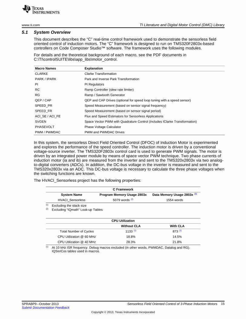
5.1 System OverviewThis document describes the “C” real-time control framework used to demonstrate the sensorless fieldoriented control of induction motors. The “C” framework is designed to run on TMS320F2803x-basedcontrollers on Code Composer Studio™ software. The framework uses the following modules.
For details and the theoretical background of each macro, see the PDF documents inC:\TI\controlSUITE\libs\app_libs\motor_control.
Macro Names ExplanationCLARKE Clarke TransformationPARK / IPARK Park and Inverse Park TransformationPI PI RegulatorsRC Ramp Controller (slew rate limiter)RG Ramp / Sawtooth GeneratorQEP / CAP QEP and CAP Drives (optional for speed loop tuning with a speed sensor)SPEED_PR Speed Measurement (based on sensor signal frequency)SPEED_FR Speed Measurement (based on sensor signal period)ACI_SE / ACI_FE Flux and Speed Estimators for Sensorless ApplicationsSVGEN Space Vector PWM with Quadrature Control (includes IClarke Transformation)PHASEVOLT Phase Voltage CalculatorPWM / PWMDAC PWM and PWMDAC Drives
In this system, the sensorless Direct Field Oriented Control (DFOC) of Induction Motor is experimentedand explores the performance of the speed controller. The induction motor is driven by a conventionalvoltage-source inverter. The TMS320F2803x control card is used to generate PWM signals. The motor isdriven by an integrated power module by means of space vector PWM technique. Two phase currents ofinduction motor (ia and ib) are measured from the inverter and sent to the TMS320x2803x via two analog-to-digital converters (ADCs). In addition, the DC-bus voltage in the inverter is measured and sent to theTMS320x2803x via an ADC. This DC-bus voltage is necessary to calculate the three phase voltages whenthe switching functions are known.
The HVACI_Sensorless project has the following properties:
C FrameworkSystem Name Program Memory Usage 2803x Data Memory Usage 2803x (1)
HVACI_Sensorless 5079 words (2) 1554 words(1) Excluding the stack size(2) Excluding “IQmath” Look-up Tables
CPU UtilizationWithout CLA With CLA
Total Number of Cycles 1133 (1) 873 (1)
CPU Utilization @ 60 MHz 18.8% 14.5%CPU Utilization @ 40 MHz 28.3% 21.8%
(1) At 10 kHz ISR frequency. Debug macros excluded (in other words, PWMDAC, Datalog and RG).IQSin/Cos tables used in macros.
15SPRABP9–October 2013 Sensorless Field Oriented Control of 3-Phase Induction MotorsSubmit Documentation Feedback
Copyright © 2013, Texas Instruments Incorporated
F8035x
CPU32 bit
I2CUARTCAN
ADC12 bit
Vref
CAP-1
PWM-1A
B
PWM-2A
B
PWM-3A
B
PWM-4A
B
PWM-5A
B
QEP
HOST
1PWM1A
2PWM1B
3PWM2A
4PWM2B
5PWM3A
6PWM3B
DC BusVoltage
FeedbackCurrent
Feedback
3-PhaseACI Motor
15 V
1H
2H
3H
1L
2L
3L
2H
DC-BusIntegrated Power Module
3H
2L 3L
1
2
3
4
5
16
TI Literature and Digital Motor Control (DMC) Library www.ti.com
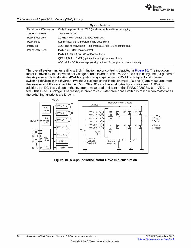
System FeaturesDevelopment/Emulation Code Composer Studio V4.0 (or above) with real-time debuggingTarget Controller TMS320F2803xPWM Frequency 10 kHz PWM (Default), 60 kHz PWMDACPWM Mode Symmetrical with a programmable dead bandInterrupts ADC, end of conversion – Implements 10 kHz ISR execution ratePeripherals Used PWM 1 / 2 / 3 for motor control
PWM 6A, 6B, 7A and 7B for DAC outputsQEP1 A,B, I or CAP1 (optional for tuning the speed loop)ADC A7 for DC Bus voltage sensing, A1 and B1 for phase current sensing
The overall system implementing a 3-ph induction motor control is depicted in Figure 10. The inductionmotor is driven by the conventional voltage-source inverter. The TMS320F2803x is being used to generatethe six pulse width modulation (PWM) signals using a space vector PWM technique, for six powerswitching devices in the inverter. Two input currents of the induction motor (ia and ib) are measured fromthe inverter and they are sent to the TMS320F2803x via two analog-to-digital converters (ADCs). Inaddition, the DC-bus voltage in the inverter is measured and sent to the TMS320F2803xvia an ADC aswell. This DC-bus voltage is necessary in order to calculate three phase voltages of induction motor whenthe switching functions are known.
Figure 10. A 3-ph Induction Motor Drive Implementation
16 Sensorless Field Oriented Control of 3-Phase Induction Motors SPRABP9–October 2013Submit Documentation Feedback
Copyright © 2013, Texas Instruments Incorporated

Initialize s/w
modules
c_int0
Initialize s/w
modules
Enable end of
conversion ISR
Initialize other
system and module
parameters
Background
LoopINT 1
SOC
EOC ISR
Save contexts and
clear interrupt flag
Execute ADC
conversion
Execute the park
and clarke trans.
Execute the PID
modules
Execute the ipark
and svgen modules
Execute the
ACI_FE and
ACI_SE modules
Execute the PWM
drive
Restore context Return
Execute the voltage
calc modules
www.ti.com TI Literature and Digital Motor Control (DMC) Library
The software flow is described in the Figure 11.
Figure 11. Software Flow
17SPRABP9–October 2013 Sensorless Field Oriented Control of 3-Phase Induction MotorsSubmit Documentation Feedback
Copyright © 2013, Texas Instruments Incorporated

Hardware Configuration (HVDMC R1.1 Kit) www.ti.com
6 Hardware Configuration (HVDMC R1.1 Kit)For an overview of the kit’s hardware and steps on how to set up this kit, see the HVMotorCtrl+PFC Howto Run Guide located at: www.ti.com/controlsuite and choose the HVMotorKit installation.
The guide will be installed at: C:\TI\controlSUITE\development_kits\HVMotorCtrl+PfcKit_v2.0\~Docs.
Some of the hardware setup instructions are captured below for quick reference.
6.1 Hardware Setup Instructions1. Open the Lid of the HV Kit2. Install the Jumpers [Main]-J3, J4 and J5, J9 for 3.3V, 5V and 15V power rails and JTAG reset line.3. Unpack the DIMM style controlCARD and place it in the connector slot of [Main]-J1. Push down
vertically using even pressure from both ends of the card until the clips snap and lock. (to remove thecard simply spread open the retaining clip with thumbs)
4. Connect a USB cable to connector [M3]-JP1.This step enables an isolated JTAG emulation to the C2000 device. [M3]-LD1 should turn on. Makesure [M3]-J5 is not populated. If the included Code Composer Studio is installed, the drivers for theonboard JTAG emulation will automatically be installed. If a Windows® installation window appears, tryto automatically install drivers from those already on your computer. The emulation drivers are found athttp://www.ftdichip.com/Drivers/D2XX.htm. The correct driver is the one listed to support the FT2232.
5. If a third party JTAG emulator is used, connect the JTAG header to [M3]-J2 and additionally [M3]-J5needs to be populated to put the onboard JTAG chip in reset.
6. Ensure that [M6]-SW1 is in the “Off” position.7. Connect 15-V DC power supply to [M6]-JP1.8. Turn on [M6]-SW1. Now [M6]-LD1 should turn on. Notice the control card LED will light up as well
indicating the control card is receiving power from the board.9. Note that the motor should be connected to the [M5]-TB3 terminals after you finish with the first
incremental build step.10. Note the DC Bus power should only be applied during incremental build levels when instructed to do
so. The two options to get DC Bus power are:(a) To use DC power supply, set the power supply output to zero and connect [Main]-BS5 and BS6 to
DC power supply and ground respectively.(b) To use AC Main Power, Connect [Main]-BS1 and BS5 to each other using banana plug cord. Now
connect one end of the AC power cord to [Main]-P1. The other end needs to be connected tooutput of a variac. Ensure that the variac output is set to zero and connected to the wall supplythrough an isolator.
Since the motor is rated at 220 V, the motor properly runs only at a certain speed and torque rangewithout saturating the PID regulators in the control loop when the DC bus is fed from 110-V AC entry. Asan option, the user can run the PFC on HV DMC drive platform as boost converter to increase the DC busvoltage level or directly connect a DC power supply.
18 Sensorless Field Oriented Control of 3-Phase Induction Motors SPRABP9–October 2013Submit Documentation Feedback
Copyright © 2013, Texas Instruments Incorporated

ACIMotor
Encoderor Tacho
15V DC
ACEntry
J3,J4,J5
J9
www.ti.com Hardware Configuration (HVDMC R1.1 Kit)
Figure 12. Using AC Power to Generate DC Bus Power
CAUTIONThe inverter bus capacitors remain charged for a long time after the high powerline supply is switched off or disconnected. Proceed with caution!
19SPRABP9–October 2013 Sensorless Field Oriented Control of 3-Phase Induction MotorsSubmit Documentation Feedback
Copyright © 2013, Texas Instruments Incorporated

ACIMotor
Encoderor Tacho
15V DC
J3,J4,J5
J9
DC Power Supply (max. 350V)+-
Hardware Configuration (HVDMC R1.1 Kit) www.ti.com
Figure 13. Using External DC Power Supply to Generate DC-Bus for the Inverter
CAUTIONThe inverter bus capacitors remain charged for a long time after the high powerline supply is switched off or disconnected. Proceed with caution!
6.2 Software Setup Instructions to Run HVACI_Sensorless ProjectFor more information, see the Software Setup for HVMotorCtrl+PFC Kit Projects section in theHVMotorCtrl+PFC Kit How to Run Guide in:C:\TI\controlSUITE\development_kits\HVMotorCtrl+PfcKit_v2.0\~Docs
1. Select the HVACI_Sensorless as the active project.2. Verify that the build level is set to 1, and then right click on the project name and select “Rebuild
Project”.3. Once the build completes, launch a debug session to load the code into the controller.4. Open a watch window and add the critical variables as shown in Figure 14 and select the appropriate
Q format for them.
20 Sensorless Field Oriented Control of 3-Phase Induction Motors SPRABP9–October 2013Submit Documentation Feedback
Copyright © 2013, Texas Instruments Incorporated

www.ti.com Hardware Configuration (HVDMC R1.1 Kit)
Figure 14. Watch Window Variables
5. Set up time graph windows by importing Graph1.graphProp and Graph2.graphProp from:C:\TI\ControlSUITE\development_kits\HVMotorCtrl+PfcKit_v2.0\HVACI_sensorless\.
6. Click on Continuous Refresh button on the top left corner of the graph tab to enable periodiccapture of data from the microcontroller.
21SPRABP9–October 2013 Sensorless Field Oriented Control of 3-Phase Induction MotorsSubmit Documentation Feedback
Copyright © 2013, Texas Instruments Incorporated

Incremental System Build for ACI Sensorless Project www.ti.com
7 Incremental System Build for ACI Sensorless ProjectThe system is gradually built up so the final system can be confidently operated. Six phases of theincremental system build are designed to verify the major software modules used in the system. Table 1summarizes the modules testing and using in each incremental system build.
Table 1. Testing Modules in Each Incremental System Build (1)
Software Module Phase 1 Phase 2 Phase 3 Phase 4 Phase 5 Phase 6PWMDAC_MACRO √ √ √ √ √ √RC_MACRO √ √ √ √RG_MACRO √ √ √ √IPARK_MACRO √√ √ √ √ √ √SVGEN_MACRO √√ √ √ √ √ √PWM_MACRO √√ √ √ √ √ √CLARKE_MACRO √√ √ √ √ √PARK_MACRO √√ √ √ √ √VOLT_MACRO √√ √ √ √ √CAP_MACRO √√ √ √SPEED_PR_MACRO √√ √ √QEP_MACRO √√ √ √PEED_FR_MACRO √√ √ √PI_MACRO (IQ) √√ √ √ √PI_MACRO (ID) √√ √ √ √ACI_FE √√ √ √ACI_SE √√ √ √PI_MACRO (SPD) √√ √√
(1) The symbol √ means this module is using and the symbol √√ means this module is testing in this phase.
7.1 Level 1 Incremental BuildKeep the motor disconnected at this step. Assuming the load and build steps described in theHVMotorCtrl+PFC Kit How To Run Guide completed successfully, this section describes the steps for a“minimum” system check-out, which confirms the operation of system interrupt, the peripheral and targetindependent I_PARK_MACRO (inverse park transformation) and SVGEN_MACRO (space vectorgenerator) modules, the peripheral dependent PWM_MACRO (PWM initializations and update) modules.1. Open HVACI_Sensorless-Settings.h.2. Select level 1 incremental build option by setting the BUILDLEVEL to LEVEL1 (#define BUILDLEVEL
LEVEL1).3. Right-click on the project name and click Rebuild Project.4. When the build is complete:
(a) Click on the debug button.(b) Reset the CPU and restart.(c) Enable real-time mode and run.(d) Set the “EnableFlag” to 1 in the watch window. The variable named “IsrTicker” will now continue to
increase, as seen in the watch window, to confirm the system interrupt is properly working.
In the software, the key variables to adjust are:• SpeedRef (Q24): for changing the rotor speed in per-unit.• VdTesting (Q24): for changing the d-qxis voltage in per-unit.• VqTesting (Q24): for changing the q-axis voltage in per-unit.
22 Sensorless Field Oriented Control of 3-Phase Induction Motors SPRABP9–October 2013Submit Documentation Feedback
Copyright © 2013, Texas Instruments Incorporated

www.ti.com Incremental System Build for ACI Sensorless Project
7.2 Level 1A (SVGEN_MACRO Test)In this level we would test the Space Vector Generator Macro (SVGEN_MACRO). The SpeedRef value isspecified to the RG_MACRO module via RC_MACRO module. The IPARK_MACRO module is generatingthe outputs to the SVGEN_MACRO module. Three outputs from SVGEN_MACRO module are monitoredvia the graph window, as shown in Figure 15, where Ta, Tb, and Tc waveform are 120° apart from eachother. Specifically, Tb lags Ta by 120° and Tc leads Ta by 120°. Check the PWM test points on the boardto observe PWM pulses (PWM-1H to 3H and PWM-1L to 3L) and ensure that the PWM module is runningproperly.
Figure 15. SVGEN Duty Cycle Outputs Ta, Tb, Tc and Tb-Tc
23SPRABP9–October 2013 Sensorless Field Oriented Control of 3-Phase Induction MotorsSubmit Documentation Feedback
Copyright © 2013, Texas Instruments Incorporated

1
2RC
c
t =p¦
Incremental System Build for ACI Sensorless Project www.ti.com
7.3 Level 1B (Testing The PWMDAC Macro)To monitor internal signal values in real time, PWM DACs are very useful tools. Present on the HV DMCboard are PWM DACs which use an external low pass filter to generate the waveforms ([Main]-J14, DAC-1 to 4). A simple first-order low-pass filter RC circuit filters out the high frequency components. Theselection of R and C value (or the time constant, τ) is based on the cut-off frequency (fc), for this type offilter; the relation is as follows:
For example, R = 1.8 kΩ and C = 100 nF results in fc = 884.2 Hz. This cut-off frequency must be belowthe PWM frequency. Use the formula above to customize low-pass filters used for the signal beingmonitored.
The DAC circuit low-pass filters ([Main]-R10 to13 and [Main]-C15 to18) are shipped with 2.2 kΩ and 220nF on the board. For more details, see Using PWM Output as a Digital-to-Analog Converter on aTMS320F280x Digital Signal Controller (SPRAA88).
Figure 16. DAC-1-4 Outputs Showing Ta, Tb, Tc and Tb-Tc Waveforms
7.4 Level 1C (PWM_MACRO and INVERTER Test)After verifying the SVGEN_MACRO module in Level 1A, the PWM_MACRO software module and the 3-phase inverter hardware are tested by looking at the low-pass filter outputs. For this purpose, if using theexternal DC power supply gradually increase the DC bus voltage and check the Vfb-U, V and W testpoints using an oscilloscope or if using AC power entry slowly change the variac to generate the DC busvoltage. Once the DC bus voltage is greater than 15 V to 20 V, you will start observing the inverter phasevoltage dividers and waveform monitoring filters (Vfb-U, Vfb-V, Vfb-W) enable the generation of thewaveform, which ensures that the inverter is working appropriately. Note that the default RC values areoptimized for AC motor state observers employing phase voltages.
24 Sensorless Field Oriented Control of 3-Phase Induction Motors SPRABP9–October 2013Submit Documentation Feedback
Copyright © 2013, Texas Instruments Incorporated

www.ti.com Incremental System Build for ACI Sensorless Project
CAUTIONAfter verifying the SVGEN_MACRO module:1. Reduce the DC bus voltage.2. Take the controller out of real-time mode (disable).
3. Reset the processor (for more details, see the HVMotorCtrl+PFC KitHow To Run Guide).
Note that after each test, this process needs to be repeated for safetypurposes. Also note that improper shutdown might halt the PWMs at somecertain states where high currents can be drawn, therefore, caution needs to betaken while doing these experiments.
25SPRABP9–October 2013 Sensorless Field Oriented Control of 3-Phase Induction MotorsSubmit Documentation Feedback
Copyright © 2013, Texas Instruments Incorporated

SV
GE
N
MA
CR
O
PW
M1
A/B
PW
M2
A/B
PW
M3
A/B
Mfu
nc_
C1
Mfu
nc_
C3
Mfu
nc_
C2
Ta Tc
Tb
Ua
lph
a
Ub
eta
PW
MD
AC
MA
CR
OM
Fu
ncC
1
MF
un
cC
2
PW
MxA
PW
MxB
Lo
w
Pa
ss
Filt
er
Cct
DA
TA
LO
G
Dlo
g1
Dlo
g2
Dlo
g3
Dlo
g4
Sc
op
eG
rap
h
Win
do
w
Alp
ha
Be
ta
IPA
RK
MA
CR
O
Ds
An
gle
Qs
Vd
Te
sti
ng
Vq
Te
sti
ng
Ta
rge
tVa
lue
RC
MA
CR
OS
etP
oin
tVa
lue
Fre
q
Sp
ee
dR
ef
Wa
tch
Win
do
w
PW
M
MA
CR
O
PW
M
HW
Sin
e/C
os
Ou
t
RG
MA
CR
O
Incremental System Build for ACI Sensorless Project www.ti.com
Figure 17. Level 1 — Incremental System Build Block Diagram
Level 1 verifies the target independent modules, duty cycles and PWM updates. The motor isdisconnected at this level.
26 Sensorless Field Oriented Control of 3-Phase Induction Motors SPRABP9–October 2013Submit Documentation Feedback
Copyright © 2013, Texas Instruments Incorporated

www.ti.com Incremental System Build for ACI Sensorless Project
7.5 Level 2 - Incremental BuildAssuming the Level 1 incremental build is completed successfully, this section verifies the analog-to-digitalconversion, Clarke/Park transformations and phase voltage calculations. Now the motor can be connectedto the HVDMC board.
In the software, the key variables to adjust are:• SpeedRef (Q24): for changing the rotor speed in per-unit.• VdTesting (Q24): for changing the d-axis voltage in per-unit.• VqTesting (Q24): for changing the q-axis voltage in per-unit.1. Open HVACI_Sensorless-Settings.h and select level 2 incremental build option by setting the
BUILDLEVEL to LEVEL2 (#define BUILDLEVEL LEVEL2) and save the file.2. Right-click on the project name and click Rebuild Project.3. When the build is complete:
(a) Click on the debug button(b) Reset the CPU and restart.(c) Enable real-time mode and run.
4. Set “EnableFlag” to 1 in the watch window. The variable named “IsrTicker” will be incrementallyincreased as seen in watch windows to confirm the interrupt working properly.
7.6 Level 2A – Testing the Phase Voltage ModuleIn this part, the phase voltage calculation module, PHASEVOLT_MACRO, will be tested. Graduallyincrease the DC bus voltage. The waveforms in Figure 18 should be observed.
Figure 18. Calculated Phase A and B Voltages By Volt1 Module, rg1.Out, and svgen_dq1.Ta
• The VphaseA, VphaseB, and VphaseC waveforms should be 120° apart from each other. Specifically,VphaseB lags VphaseA by120° (Figure 18) and VphaseC leads VphaseA by 120.Alternatively, users can modify the datalog setting to verify the following relation between the signals:
• The Valpha waveform should be the same as the VphaseA waveform.• The Valpha waveform should be leading the Vbeta waveform by 90° at the same magnitude.
Note that the open loop experiments are meant to test the ADCs, inverter stage, software modules, and soforth. Running the motor under load or at various operating points is not recommended.
27SPRABP9–October 2013 Sensorless Field Oriented Control of 3-Phase Induction MotorsSubmit Documentation Feedback
Copyright © 2013, Texas Instruments Incorporated

Incremental System Build for ACI Sensorless Project www.ti.com
7.7 Phase 2B – Testing the Clarke ModuleIn this part the Clarke module will be tested. The three measured line currents are transformed to twophase dq currents in a stationary reference frame. The outputs of this module can be checked from thegraph window.
Verify the following:• The clarke1.Alpha waveform leads the clarke1.Beta waveform by 90° at the same magnitude.• The clarke1.Alpha waveform is the same as the clarke1.As waveform.
The measured line current must be lagging with the reconstructing phase voltage because of the nature ofthe ACI motor.
As mentioned in the previous section, three input switching functions may not be functioning correctly (seethis module documentation for details). This can be easily checked as follows (Note: You may need tomodify datalog settings and graph windows settings to observe these signals):• The clarke1.Alpha waveform lags the Valpha waveform at an angle by nature of the reactive load of
Induction motor.• The clarke1.Beta waveform lags the Vbeta waveform at the same angle.• If the clarke1.Alpha and Valpha or clarke1.Beta and Vbeta waveforms in the previous step are not truly
affecting the lagging relationship, then set OutofPhase to 1 at the beginning of thePHASEVOLT_MACRO module.
Figure 19. The Waveforms of Phase A Voltage and Current and Phase B Voltage and Current
Since the low side current measurement technique is used employing shunt resistors on inverter phaselegs, the phase current waveforms observed from current test points ([M5]-Ifb-U, and [M5]-Ifb-V) arecomposed of pulses, as shown in Figure 20.
28 Sensorless Field Oriented Control of 3-Phase Induction Motors SPRABP9–October 2013Submit Documentation Feedback
Copyright © 2013, Texas Instruments Incorporated

www.ti.com Incremental System Build for ACI Sensorless Project
Figure 20. Amplified Phase A Current
7.8 Level 2B – Adjusting PI LimitsNote that the vectorial sum of d-q PI outputs should be less than 1.0 which refers to maximum duty cyclefor SVGEN macro. Another duty cycle limiting factor is the current sense through shunt resistors whichdepends on hardware/software implementation. Depending on the application requirements 3, 2 or asingle shunt resistor can be used for current waveform reconstruction. The higher number of shuntresistors allow higher duty cycle operation and better DC bus utilization.
Run the system with default VdTesting, VqTesting and SpeedRef and gradually increase VdTesting andVqTesting values. Meanwhile, watch the current waveforms in the graph window. Increase until you noticedistorted current waveforms and write down the maximum allowed VdTesting and VqTesting values.Ensure that these values are consistent with expected d-q current component maximums while runningthe motor. After this build level, PI outputs will automatically generate the voltage reference and determinethe PWM duty cycle depending on the d-q current demand, therefore set pi_id.Umax/min andpi_iq.Umax/min according to recorded VdTesting and VqTesting values, respectively.
Note: Running the motor without proper PI limits can yield distorted current waveforms and unstableclosed loop operations which may damage the hardware.
Bring the system to a safe stop, as described at the end of build 1 (Section 7.1), by reducing the busvoltage and taking the controller out of real-time mode and reset.
29SPRABP9–October 2013 Sensorless Field Oriented Control of 3-Phase Induction MotorsSubmit Documentation Feedback
Copyright © 2013, Texas Instruments Incorporated

PW
M1
A/B
PW
M2
A/B
PW
M3
A/B
Mfu
nc_
C1
Mfu
nc_
C3
Mfu
nc_
C2
Ta
Tc
Tb
Ua
lph
a
Ub
eta
PW
MD
AC
MA
CR
OM
Fu
ncC
1
MF
un
cC
2
PW
MxA
PW
MxB
Low
Pass
Filt
er
Cct
DA
TA
LO
G
Dlo
g1
Dlo
g2
Dlo
g3
Dlo
g4
Sco
pe
Gra
ph
Win
do
w
Alp
ha
Be
ta
Ds
An
gle
Qs
Vd
Te
sti
ng
Vq
Te
sti
ng
Ta
rge
tVa
lue
RC
MA
CR
OS
etP
oin
tVa
lue
RG
MA
CR
OF
req
Sp
ee
dR
ef
AC
I
Moto
r
3-P
hase
Invert
er
PW
M
MA
CR
O
PW
M
HW
AD
CIn
1 (
Ia)
AD
CIn
2 (
Ib)
AD
CIn
3 (
Ic)
IPA
RK
MA
CR
O
CL
AR
KE
MA
CR
OA
dcR
esu
lt0
Ad
cR
esu
lt1
As
Bs
Alp
ha
Be
ta
PA
RK
MA
CR
O
Alp
ha
Be
ta
Ou
t
AD
CIn
4 (
Vd
c)
Ad
cR
esu
lt3
SV
GE
N
MA
CR
O
AD
C
HW
Va
bc
Va
lph
a
Vb
eta
Sin
e/C
os
Ta
Tc
Tb
DcB
usV
olt
AD
C
MA
CR
O
PH
AS
E
VO
LT
MA
CR
O
Incremental System Build for ACI Sensorless Project www.ti.com
Figure 21. Level 2 — Incremental System Build Block Diagram
Level 2 verifies the analog-to-digital conversion, offset compensation, clarke / park transformations.
30 Sensorless Field Oriented Control of 3-Phase Induction Motors SPRABP9–October 2013Submit Documentation Feedback
Copyright © 2013, Texas Instruments Incorporated

www.ti.com Incremental System Build for ACI Sensorless Project
7.9 Level 3 Incremental BuildAssuming the previous section is completed successfully, this section verifies the dq-axis currentregulation performed by PI modules and speed measurement modules (optional). To confirm the operationof current regulation, the gains of these two PI controllers are necessarily tuned for proper operation.1. Open HVACI_Sensorless-Settings.h and select level 3 incremental build option by setting the
BUILDLEVEL to LEVEL3 (#define BUILDLEVEL LEVEL3).2. Right-click on the project name and click Rebuild Project.3. When the build completes:
(a) Click on the debug button.(b) Reset CPU and restart.(c) Enable Real-time mode and run.(d) Set “EnableFlag” to 1 in the watch window. The variable named “IsrTicker” will be incrementally
increased as seen in watch windows to confirm the interrupt working properly.
In the software, the key variables to adjust are:• SpeedRef (Q24): for changing the rotor speed in per-unit.• IdRef (Q24): for changing the d-qxis voltage in per-unit.• IqRef (Q24): for changing the q-axis voltage in per-unit.
In this build, the motor is supplied by AC input voltage and the (AC) motor current is dynamically regulatedby using PI module through the park transformation on the motor currents.
The steps are:1. Launch a debug session, enable time mode and run the project.2. Set SpeedRef to 0.3 pu (or another suitable value if the base speed is different), Idref to a certain
value to generate rated flux.3. Gradually increase voltage at variac / dc power supply to get an appropriate DC-bus voltage.4. Check pi_id.Fdb in the watch windows with continuous refresh feature whether or not it should be
keeping track pi_id.Ref for PI module. If not, adjust its PI gains properly.5. To confirm these two PI modules, try different values of pi_id.Ref and pi_iq.Ref or SpeedRef.6. For both PI controllers, the proportional, integral, derivative and integral correction gains may be re-
tuned to have the satisfied responses.7. Bring the system to a safe stop, as described at the end of build 1 (Section 7.1), by reducing the bus
voltage and taking the controller out of real-time mode and reset.
While running this build, the current waveforms in the CCS graphs should appear as shown in Figure 22.
31SPRABP9–October 2013 Sensorless Field Oriented Control of 3-Phase Induction MotorsSubmit Documentation Feedback
Copyright © 2013, Texas Instruments Incorporated

Incremental System Build for ACI Sensorless Project www.ti.com
Figure 22. Svgen_dq1.Ta, Phase A Voltage, and Phase A and B Current Waveforms
7.10 Level 3B – QEP / SPEED_FR Test (Optional for Speed-Loop Tuning)This section verifies the QEP1 driver and its speed calculation. Qep drive macro determines the rotorposition and generates a direction (of rotation) signal from the shaft position encoder pulses. Make surethat the output of the incremental encoder is connected to [Main]-H1 and QEP/SPEED_FR macros areinitialized properly in the HVACI_Sensorless.c file depending on the features of the speed sensor. Refer tothe PDF files regarding the details of related macros in the motor control folder(C:\TI\controlSUITE\libs\app_libs\motor_control).
The steps to verify these two software modules related to the speed measurement are:1. Set SpeedRef to 0.3 pu (or another suitable value if the base speed is different).2. Compile, load, and run program with real-time mode and then increase voltage at variac and DC power
supply to get the appropriate DC-bus voltage. Now the motor is running close to reference speed.3. Check the “speed1.Speed” in the watch windows with continuous refresh feature whether or not the
measured speed is less than SpeedRef a little bit due to a slip of motor.4. To confirm these modules, try different values of SpeedRef to test the Speed.5. Use oscilloscope to view the electrical angle output, ElecTheta, from QEP_MACRO module and the
emulated rotor angle, Out, from RG_MACRO at PWMDAC outputs with external low-pass filters.6. Check that both ElecTheta and Out are of saw-tooth wave shape and have the same period. If the
measured angle is in opposite direction, then change the order of motor cables connected to inverteroutput (TB3 for HVDMC kit).
7. Check from Watch Window that qep1.IndexSyncFlag is set back to 0xF0 every time it reset to 0 byhand. Add the variable to the watch window if it is not already in the watch window.
8. Bring the system to a safe stop, as described at the end of build 1 (Section 7.1), by reducing the busvoltage and taking the controller out of real-time mode and reset.
7.11 Level 3C – CAP / SPEED_PR Test (Optional for Speed-Loop Tuning)In this case, the CAP1 input is chosen to detect the edge. If available, make sure that the sensor output isconnected to [Main]-H1 and CAP/SPEED_PR macros are initialized properly in the HVACI_Sensorless.cfile depending on the features of the speed sensor. Typically the capture is used to measure speed whena simple low cost speed sensing system is available. The sensor generates pulses when detecting theteeth of a sprocket or gear and the capture drive provides the instantaneous value of the selected timebase (GP Timer) captured on the occurrence of an event. Refer to the pdf files regarding the details ofrelated macros in the motor control folder (C:\TI\controlSUITE\libs\app_libs\motor_control).
32 Sensorless Field Oriented Control of 3-Phase Induction Motors SPRABP9–October 2013Submit Documentation Feedback
Copyright © 2013, Texas Instruments Incorporated

60_
RPM TEETHHz
square wave
´¦ =
www.ti.com Incremental System Build for ACI Sensorless Project
The steps to verify these two software modules related to the speed measurement are:1. Set SpeedRef to 0.3 pu (or another suitable value if the base speed is different).2. Compile, load, and run program with real time mode and then increase voltage at variac / dc power
supply to get the appropriate DC-bus voltage. Now the motor is running reference speed.3. Check the “speed2.Speed” in the watch windows with continuous refresh feature whether or not they
should be less than SpeedRef a little bit due to a slip of motor.4. To confirm these modules, try different values of SpeedRef to test the Speed.5. Reduce voltage at variac and DC power supply to zero, halt program and stop real time mode. Now
the motor is stopping.
An alternative to verify these two software modules without running the motor is to use a functiongenerator. The key steps can be explained as follows:1. Use a function generator to generate the 3.3 V (DC) square-wave with the desired frequency
corresponding to the number of teeth in sprocket and the wanted speed in rpm. Then, connect only thepulse signal and ground wires from the function generator to HVDMC board. The desired frequency ofthe square-wave produced by function generator can be formulated as:
where RPM is the wanted speed in rpm, and TEETH is the number of teeth in sprocket.2. Compile, load, and run program with real time mode and then increase voltage at variac to get the
appropriate DC-bus voltage. Now the motor is running. Note that the SpeedRef could be set to anynumber.
3. Check the speed2.Speed and speed2.SpeedRpm in the watch windows with continuous refreshfeature whether or not they should be corresponding to the wanted speed that is chosen before.
4. To confirm these modules, change different frequencies of square-wave produced by functiongenerator with corresponding wanted (known) speed to check the Speed and SpeedRpm.
5. Bring the system to a safe stop, as described at the end of build 1 (Section 7.1), by reducing the busvoltage and taking the controller out of real-time mode and reset.
33SPRABP9–October 2013 Sensorless Field Oriented Control of 3-Phase Induction MotorsSubmit Documentation Feedback
Copyright © 2013, Texas Instruments Incorporated

SV
GE
N
MA
CR
O
PW
M1
A/B
PW
M2
A/B
PW
M3
A/B
Mfu
nc_C
1
Mfu
nc_C
3
Mfu
nc_C
2
Ta
Tc
Tb
Ualp
ha
Ubeta
Alp
ha
Beta
Qs
Ds
IqR
ef
IdR
ef
Targ
etV
alu
e
RC
MA
CR
OS
etP
oin
tValu
eF
req
Sp
eed
Ref
AC
I
Mo
tor
PW
M
MA
CR
O
PW
M
HW
IPA
RK
MA
CR
O
CLA
RK
E
MA
CR
OA
s
Bs
Alp
ha
Beta
PA
RK
MA
CR
O
Alp
ha
Beta
CA
P
MA
CR
O
CA
P
HW
QE
Pn
CA
Pn
SP
EE
D F
R
MA
CR
OE
lecT
heta
Direction
QE
P
MA
CR
O
QE
P
HW
Ele
cT
heta
SP
EE
D P
R
MA
CR
O
Speed
SpeedR
pm
Speed
SpeedR
pm
Q_O
ut
Ref
PI
MA
CR
O
Iq R
eg
PI
MA
CR
O
Id R
eg
D_O
ut
Fbk
Ref
Fbk
Out
Sin
e/C
os
Ds
Qs
PH
AS
E
VO
LT
MA
CR
O
Vabc
Valp
ha
Vbeta
AD
CIn
1 (
Ia)
AD
CIn
2 (
Ib)
AD
CIn
3 (
Ic)
AdcR
esult0
AdcR
esult1
AD
CIn
4 (
Vdc)
AdcR
esult3
AD
C
HW
3-P
ha
se
Inve
rte
r
Ta
Tb
Tc
DcB
usV
olt
RG
MA
CR
O
AD
C
MA
CR
O
Incremental System Build for ACI Sensorless Project www.ti.com
Figure 23. Level 3 — Incremental System Build Block Diagram
Level 3 verifies the dq-axis current regulation performed by PI macros and speed measurement modules.
34 Sensorless Field Oriented Control of 3-Phase Induction Motors SPRABP9–October 2013Submit Documentation Feedback
Copyright © 2013, Texas Instruments Incorporated

www.ti.com Incremental System Build for ACI Sensorless Project
7.12 Level 4 Incremental BuildAssuming the previous section is completed successfully; this section verifies flux estimation (ACI_FE)and open-loop speed estimation (ACI_SE), respectively.1. Open HVACI_Sensorless-Settings.h and select level 4 incremental build option by setting the
BUILDLEVEL to LEVEL4 (#define BUILDLEVEL LEVEL4).2. Right-click on the project name and click Rebuild Project.3. When the build completes:
(a) Click on the debug button.(b) Reset CPU and restart.(c) Enable Real-time mode and run.(d) Set “EnableFlag” to 1 in the watch window. The variable named “IsrTicker” will be incrementally
increased as seen in watch windows to confirm the interrupt working properly.
The key variables to adjust are:• SpeedRef (Q24): for changing the rotor speed in per-unit.• IdRef (Q24): for changing the d-qxis voltage in per-unit.• IqRef (Q24): for changing the q-axis voltage in per-unit.
The tuning of proportional and integral gains (Kp_fe and Ki_fe) inside the flux estimator may be critical forvery low speed operation. The key steps are:1. Set SpeedRef to 0.3 pu (or another suitable value if the base speed is different).2. Compile, load, and run program with real time mode and then increase voltage at variac / dc power
supply to get the appropriate DC-bus voltage. Now the motor is running close to reference speed.3. Compare fe1.ThetaFlux with rg1.Out via PWMDAC with external low-pass filter and an oscilloscope.
They should be identical with a small phase shift.4. If fe1.ThetaFlux does not give the ramp waveform, the Kp and Ki inside the flux estimator are required
to be re-tuned (likely to be reduced).5. To confirm this flux estimator, try different values of SpeedRef.6. Compare se1.WrHat with reference speed or measured speed in the watch windows with continuous
refresh feature whether or not it should be nearly the same.7. To confirm this open-loop speed estimator, try different values of SpeedRef.
While running this build, the current waveforms in the CCS graphs should appear as shown in Figure 24.
Figure 24. Estimated d and q Fluxes With Estimated Theta and Phase A Current Waveform
35SPRABP9–October 2013 Sensorless Field Oriented Control of 3-Phase Induction MotorsSubmit Documentation Feedback
Copyright © 2013, Texas Instruments Incorporated

SV
GE
N
MA
CR
O
PW
M1
A/B
PW
M2
A/B
PW
M3
A/B
Mfu
nc_
C1
Mfu
nc_
C3
Mfu
nc_
C2
Ta
Tc
Tb
Ua
lph
a
Ub
eta
Alp
ha
Be
ta
Qs
Ds
IqR
ef
IdR
ef
Ta
rge
tVa
lue
RC
MA
CR
OS
etP
oin
tVa
lue
Fre
q
Sp
ee
dR
ef
AC
I
Moto
r
PW
M
MA
CR
O
PW
M
HW
IPA
RK
MA
CR
O
CL
AR
KE
MA
CR
OA
s
Bs
Alp
ha
Be
ta
Alp
ha
Be
ta
QE
Pn
SP
EE
D F
R
MA
CR
OE
lecT
he
ta
Dire
ctio
nQ
EP
MA
CR
O
QE
P
HW
Sp
ee
d
Sp
ee
dR
pm
Q_
Ou
tR
ef
PI
MA
CR
O
Iq R
eg
PI
MA
CR
O
Id R
eg
D_
Ou
t
Fb
k
Re
f
Fb
k
Ou
t
Ds
Qs
PH
AS
E
VO
LT
MA
CR
O
Va
bc
Va
lph
a
Vb
eta
AD
CIn
1 (
Ia)
AD
CIn
2 (
Ib)
AD
CIn
3 (
Ic)
Ad
cR
esu
lt0
Ad
cR
esu
lt1
AD
CIn
4 (
Vd
c)
Ad
cR
esu
lt3
AD
C
HW
3-P
hase
Invert
er
Ta
Tb
Tc
DcB
usV
olt
RG
MA
CR
O
AD
C
MA
CR
O
AC
I_F
E
MA
CR
OV
alp
ha
Vb
eta
Isa
lph
a
Isb
eta
Sin
e/C
os
Isb
eta
Th
eta
Flu
x
PsiD
rs
PsiQ
rs
Isa
lph
a
Estim
ate
d
Sp
ee
d
PA
RK
MA
CR
O
AC
I_S
E
MA
CR
O
Incremental System Build for ACI Sensorless Project www.ti.com
Figure 25. Level 4 — Incremental System Build Block Diagram
Level 4 verifies the flux and speed estimation performed by ACI_FE and ACI_SE.
36 Sensorless Field Oriented Control of 3-Phase Induction Motors SPRABP9–October 2013Submit Documentation Feedback
Copyright © 2013, Texas Instruments Incorporated

www.ti.com Incremental System Build for ACI Sensorless Project
7.13 Level 5 Incremental BuildAssuming the previous section is completed successfully, this section verifies the speed regulatorperformed by PI module. The system speed loop is closed by using the measured speed as a feedback.1. Open HVACI_Sensorless-Settings.h and select level 5 incremental build option by setting the
BUILDLEVEL to LEVEL5 (#define BUILDLEVEL LEVEL5).2. Right-click on the project name and click Rebuild Project.3. When the build is complete:
(a) Click on the debug button.(b) Reset CPU and restart.(c) Enable Real-time mode and run.(d) Set “EnableFlag” to 1 in the watch window. The variable named “IsrTicker” will be incrementally
increased as seen in watch windows to confirm the interrupt working properly.
The key variables to adjust are:• SpeedRef (Q24): for changing the rotor speed in per-unit.• IdRef (Q24): for changing the d-qxis voltage in per-unit.
The speed loop is closed by using measured speed. The motor can spin only one direction when themeasured speed (from capture driver) does not give information about the direction like QEP-based speedmeasurement. Therefore, if the speed sensor is not an incremental encoder, the SpeedRef is required tobe positive. The key steps are:
7.13.1 Level 5A1. Compile, load, and run program with real time mode.2. Set SpeedRef to 0.3 pu (or another suitable value if the base speed is different).3. Add the soft-switch variables “lsw” to the watch window in order to switch from current loop to speed
loop. In the code lsw manages the loop setting as follows:• lsw=0, closes the current loop.• lsw=1, close the speed loop.
4. Set lsw to 1. Gradually increase voltage at variac / dc power supply to get an appropriate DC-busvoltage and now the motor is running around the reference speed (0.3 pu).
5. Gradually increase voltage at variac / dc power supply to get an appropriate DC-bus voltage and nowthe motor is running around the reference speed (0.3 pu).
6. Compare Speed with SpeedRef in the watch windows with continuous refresh feature whether or not itshould be nearly the same.
7. To confirm this speed PI module, try different values of SpeedRef (positive only).8. For speed PI controller, the proportional, integral, derivative and integral correction gains may be re-
tuned to have the satisfied responses.9. At very low speed range, the performance of speed response relies heavily on the good rotor flux
angle computed by flux estimator.10. Bring the system to a safe stop, as described at the end of build 1 (Section 7.1), by reducing the bus
voltage and taking the controller out of real-time mode and reset.11. Note that the IdRef is set to be constant at a certain value that is not too much for driving the motor.
Practically, you can calculate IdRef from the rated flux condition.
37SPRABP9–October 2013 Sensorless Field Oriented Control of 3-Phase Induction MotorsSubmit Documentation Feedback
Copyright © 2013, Texas Instruments Incorporated

Incremental System Build for ACI Sensorless Project www.ti.com
7.13.2 Level 5B (Alternative Method)In order to test ACI_FE only:1. Disconnect the speed PI and Iq PI modules.2. Apply constant “Iqref” as the reference to Iq PI as shown in Level 5B.
If the ACI_FE runs properly, the motor should spin smoothly. If not, check the parameters inHVACI_Sensorless-Settings.h.
3. Ensure that the base (pu) quantities are set to maximum measurable current, voltage, and motorelectrical parameters are correct. The DC bus voltage should be high enough in order not to saturatethe PI outputs.
4. Run the same experiment again and keep tuning ACI_FE gains. Note that, in this scheme the speed isnot controlled, therefore a non-zero torque (Iq) reference will spin the motor very fast unless loaded.Therefore keep the Iqref low (typically less than 0.1 pu depending on the experimental setup) and loadthe motor using a brake, generator, and other parts.
5. Increase Iqref or reduce the amount of load, if the motor speed is too low or the generated torque bythe motor is not enough to handle the applied load. After tuning the ACI_FE, add speed PI into thesystem as shown in the block diagram and tune it, if needed. This method will help the user tuneACI_FE and speed PI separately.
38 Sensorless Field Oriented Control of 3-Phase Induction Motors SPRABP9–October 2013Submit Documentation Feedback
Copyright © 2013, Texas Instruments Incorporated

SV
GE
N
MA
CR
O
PW
M1
A/B
PW
M2
A/B
PW
M3
A/B
Mfu
nc_
C1
Mfu
nc_
C3
Mfu
nc_
C2
Ta
Tc
Tb
Ualp
ha
Ube
ta
Alp
ha
Be
ta
Qs
Ds
IdR
ef
AC
I
Moto
r
PW
M
MA
CR
O
PW
M
HW
IPA
RK
MA
CR
O
CLA
RK
E
MA
CR
OA
s
Bs
Alp
ha
Beta
Alp
ha
Beta
QE
Pn
SP
EE
D F
R
MA
CR
OE
lecT
he
ta
Directio
nQ
EP
MA
CR
O
QE
P
HW
Sp
ee
d
Sp
ee
dR
pm
Q_
Ou
tR
ef
PI
MA
CR
O
Iq R
eg
PI
MA
CR
O
Id R
eg
D_
Ou
t
Fb
k
Re
f
Fb
k
Ds
Qs
PH
AS
E
VO
LT
MA
CR
O
Vab
c
Va
lph
a
Vbe
ta
AD
CIn
1 (
Ia)
AD
CIn
2 (
Ib)
AD
CIn
3 (
Ic)
Ad
cR
esult0
AdcR
esu
lt1
AD
CIn
4 (
Vdc)
Ad
cR
esult3
AD
C
HW
3-P
hase
Invert
er
Ta
Tb
Tc
DcB
usV
olt
AD
C
MA
CR
O
AC
I_F
E
MA
CR
OV
alp
ha
Vb
eta
Isa
lph
a
Isb
eta
Sin
e/C
os
Isb
eta
Th
eta
Flu
x
PsiD
rs
PsiQ
rs
Isa
lph
a
Estim
ate
d
Sp
ee
d
PA
RK
MA
CR
O
AC
I_S
E
MA
CR
O
PI
MA
CR
O
Sp
d R
eg
Sp
d_
Ou
t
Re
f
Fb
k
Sp
ee
dR
ef
www.ti.com Incremental System Build for ACI Sensorless Project
Figure 26. Level 5A — Incremental System Build Block Diagram
Level 5 verifies the speed PI module and estimated theta (lsw=1).
39SPRABP9–October 2013 Sensorless Field Oriented Control of 3-Phase Induction MotorsSubmit Documentation Feedback
Copyright © 2013, Texas Instruments Incorporated

SV
GE
N
MA
CR
O
PW
M1
A/B
PW
M2
A/B
PW
M3
A/B
Mfu
nc_C
1
Mfu
nc_C
3
Mfu
nc_C
2
Ta
Tc
Tb
Ualp
ha
Ubeta
Alp
ha
Beta
Qs
Ds
IdR
ef
AC
I
Mo
tor
PW
M
MA
CR
O
PW
M
HW
IPA
RK
MA
CR
O
CLA
RK
E
MA
CR
OA
s
Bs
Alp
ha
Beta
Alp
ha
Beta
QE
Pn
SP
EE
D F
R
MA
CR
OE
lecT
heta
Direction
QE
P
MA
CR
O
QE
P
HW
Speed
SpeedR
pm
Q_O
ut
Ref
PI
MA
CR
O
Iq R
eg
PI
MA
CR
O
Id R
eg
D_O
ut
Fbk
Ref
Fbk
Ds
Qs
PH
AS
E
VO
LT
MA
CR
O
Vabc
Valp
ha
Vbeta
AD
CIn
1 (
Ia)
AD
CIn
2 (
Ib)
AD
CIn
3 (
Ic)
AdcR
esult0
AdcR
esult1
AD
CIn
4 (
Vdc)
AdcR
esult3
AD
C
HW
3-P
ha
se
Inve
rte
r
Ta
Tb
Tc
DcB
usV
olt
AD
C
MA
CR
O
AC
I_F
E
MA
CR
OV
alp
ha
Vbeta
Isalp
ha
Isbeta
Sin
e/C
os
Isbeta
Theta
Flu
x
PsiD
rs
PsiQ
rs
Isalp
ha
Estim
ate
d
Speed
PA
RK
MA
CR
O
AC
I_S
E
MA
CR
O
IqR
ef
Incremental System Build for ACI Sensorless Project www.ti.com
Figure 27. Level 5B — Incremental System Build Block Diagram
Level 5 verifies the estimated theta.
40 Sensorless Field Oriented Control of 3-Phase Induction Motors SPRABP9–October 2013Submit Documentation Feedback
Copyright © 2013, Texas Instruments Incorporated

www.ti.com Incremental System Build for ACI Sensorless Project
7.14 Level 6 Incremental BuildAssuming the previous section is completed successfully, this section verifies the speed regulatorperformed by PI module. The system speed loop is closed by using the estimated speed as a feedback.1. Open HVACI_Sensorless-Settings.h and select level 6 incremental build option by setting the
BUILDLEVEL to LEVEL6 (#define BUILDLEVEL LEVEL6).2. Right-click on the project name and click Rebuild Project.3. When the build is complete:
(a) Click on the debug button.(b) Reset CPU and restart.(c) Enable Real-time mode and run.(d) Set “EnableFlag” to 1 in the watch window. The variable named “IsrTicker” will be incrementally
increased as seen in watch windows to confirm the interrupt working properly.
The key variables to adjust are:• SpeedRef (Q24): for changing the rotor speed in per-unit.• IdRef (Q24): for changing the d-qxis voltage in per-unit.
The speed loop is closed by using estimated speed. Unlike the Capture based sensored system inprevious build, the motor can spin both directions because the estimated speed (from open-loop speedestimator) gives information about the direction. Therefore, the SpeedRef can be either positive ornegative value. The key steps are:1. Compile, load, and run program with real time mode.2. Set SpeedRef to 0.3 pu (or another suitable value if the base speed is different).3. Set lsw to 1. Gradually increase voltage at variac / dc power supply to get an appropriate DC-bus
voltage and now the motor is running with this reference speed (0.3 pu).4. Compare se1.WrHat with SpeedRef in the watch windows with continuous refresh feature whether or
not it should be nearly the same.5. To confirm this speed PI module, try different values of SpeedRef (positive or negative).6. For speed PI controller, the proportional, integral, derivative and integral correction gains may be re-
tuned to have the satisfied responses.7. At very low speed range, the performance of speed response relies heavily on the good rotor flux
angle computed by flux estimator.8. Bring the system to a safe stop, as described at the end of build 1 (Section 7.1), by reducing the bus
voltage and taking the controller out of real-time mode and reset.9. Note that the IdRef is set to be constant at a certain value that is not too much for driving the motor.
Practically, you can calculate IdRef from the rated flux condition and follow a flux weakening profile athigh speed region.
NOTE: Using scheme 6B is recommended until completing the loop-tuning process to achievesmooth start-up. This scheme employs a soft loop-switch in the code for sensorless speedloop transient. For this purpose, add the soft-switch variable “lsw” to watch window and set"lsw" to 1 in order close the speed loop. Each time, close the speed loop earlier manuallyfrom the watch window until achieving direct sensorless start-up.
As a mid-step in between level 5 and level 6, a soft switch can be used in level 5A to change the speed PIfeedback from sensor based speed measurement to estimated speed. In this case, the initial speedestimation ambiguities will be handled by measured speed until the system is perfectly tuned.
During running this build, the current waveforms in the CCS graphs should appear as in Figure 28.
41SPRABP9–October 2013 Sensorless Field Oriented Control of 3-Phase Induction MotorsSubmit Documentation Feedback
Copyright © 2013, Texas Instruments Incorporated

Incremental System Build for ACI Sensorless Project www.ti.com
Figure 28. Phase A and B Current With Estimated Theta and Phase A Voltage Waveforms
Figure 29. Flux and Torque Components of the Stator Current in the Synchronous Reference Frame
The flux and torque components of the stator current in the synchronous reference frame are under 1.0 pustep-load and 0.3 pu speed monitored from the PWMDAC outputs.
42 Sensorless Field Oriented Control of 3-Phase Induction Motors SPRABP9–October 2013Submit Documentation Feedback
Copyright © 2013, Texas Instruments Incorporated

SV
GE
N
MA
CR
O
PW
M1
A/B
PW
M2
A/B
PW
M3
A/B
Mfu
nc_
C1
Mfu
nc_
C3
Mfu
nc_
C2
Ta
Tc
Tb
Ua
lph
a
Ub
eta
Alp
ha
Be
ta
Qs
Ds
IdR
ef
AC
I
Moto
r
PW
M
MA
CR
O
PW
M
HW
IPA
RK
MA
CR
O
CL
AR
KE
MA
CR
OA
s
Bs
Alp
ha
Be
ta
Alp
ha
Be
ta
Q_
Ou
tR
ef
PI
MA
CR
O
Iq R
eg
PI
MA
CR
O
Id R
eg
D_
Ou
t
Fb
k
Re
f
Fb
k
Ds
Qs
PH
AS
E
VO
LT
MA
CR
O
Va
bc
Va
lph
a
Vb
eta
AD
CIn
1 (
Ia)
AD
CIn
2 (
Ib)
AD
CIn
3 (
Ic)
Ad
cR
esu
lt0
Ad
cR
esu
lt1
AD
CIn
4 (
Vd
c)
Ad
cR
esu
lt3
AD
C
HW
3-P
hase
Invert
er
Ta
Tb
Tc
DcB
usV
olt
AD
C
MA
CR
O
AC
I_F
E
MA
CR
OV
alp
ha
Vb
eta
Isa
lph
a
Isb
eta
Sin
e/C
os
Isb
eta
Th
eta
Flu
x
PsiD
rs
PsiQ
rs
Isa
lph
a
Estim
ate
d
Sp
ee
d
PA
RK
MA
CR
O
AC
I_S
E
MA
CR
O
PI
MA
CR
O
Sp
d R
eg
Sp
d_
Ou
t
Re
f
Fb
k
Sp
ee
dR
ef
www.ti.com Incremental System Build for ACI Sensorless Project
Figure 30. Level 6A — Incremental System Build Block Diagram
Level 6 verifies the complete system.
43SPRABP9–October 2013 Sensorless Field Oriented Control of 3-Phase Induction MotorsSubmit Documentation Feedback
Copyright © 2013, Texas Instruments Incorporated
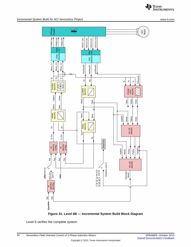
SV
GE
N
MA
CR
O
PW
M1
A/B
PW
M2
A/B
PW
M3
A/B
Mfu
nc_
C1
Mfu
nc_
C3
Mfu
nc_
C2
Ta
Tc
Tb
Ua
lph
a
Ub
eta
Alp
ha
Be
ta
Qs
Ds
IdR
ef
AC
I
Moto
r
PW
M
MA
CR
O
PW
M
HW
IPA
RK
MA
CR
O
CL
AR
KE
MA
CR
OA
s
Bs
Alp
ha
Be
ta
Alp
ha
Be
ta
Q_
Ou
tR
ef
PI
MA
CR
O
Iq R
eg
PI
MA
CR
O
Id R
eg
D_
Ou
t
Fb
k
Re
f
Fb
k
Ds
Qs
PH
AS
E
VO
LT
MA
CR
O
Va
bc
Va
lph
a
Vb
eta
AD
CIn
1 (
Ia)
AD
CIn
2 (
Ib)
AD
CIn
3 (
Ic)
Ad
cR
esu
lt0
Ad
cR
esu
lt1
AD
CIn
4 (
Vd
c)
Ad
cR
esu
lt3
AD
C
HW
3-P
hase
Invert
er
Ta
Tb
Tc
DcB
usV
olt
AD
C
MA
CR
O
AC
I_F
E
MA
CR
OV
alp
ha
Vb
eta
Isa
lph
a
Isb
eta
Sin
e/C
os
Isb
eta
Th
eta
Flu
x
PsiD
rs
PsiQ
rs
Isa
lph
a
Estim
ate
d
Sp
ee
d
PA
RK
MA
CR
O
AC
I_S
E
MA
CR
O
PI
MA
CR
O
Sp
d R
eg
Sp
d_
Ou
t
Re
f
Fb
k
Sp
ee
dR
ef
IqR
ef
(lw
s=
0)
(lw
s=
1)
rmp
.Ou
t
(lsw
=0
)
Th
eta
Flu
x(lsw
=1
)
Incremental System Build for ACI Sensorless Project www.ti.com
Figure 31. Level 6B — Incremental System Build Block Diagram
Level 6 verifies the complete system.
44 Sensorless Field Oriented Control of 3-Phase Induction Motors SPRABP9–October 2013Submit Documentation Feedback
Copyright © 2013, Texas Instruments Incorporated

www.ti.com References
8 References• Using PWM Output as a Digital-to-Analog Converter on a TMS320F280x Digital Signal Controller
(SPRAA88)
45SPRABP9–October 2013 Sensorless Field Oriented Control of 3-Phase Induction MotorsSubmit Documentation Feedback
Copyright © 2013, Texas Instruments Incorporated

IMPORTANT NOTICE
Texas Instruments Incorporated and its subsidiaries (TI) reserve the right to make corrections, enhancements, improvements and otherchanges to its semiconductor products and services per JESD46, latest issue, and to discontinue any product or service per JESD48, latestissue. Buyers should obtain the latest relevant information before placing orders and should verify that such information is current andcomplete. All semiconductor products (also referred to herein as “components”) are sold subject to TI’s terms and conditions of salesupplied at the time of order acknowledgment.
TI warrants performance of its components to the specifications applicable at the time of sale, in accordance with the warranty in TI’s termsand conditions of sale of semiconductor products. Testing and other quality control techniques are used to the extent TI deems necessaryto support this warranty. Except where mandated by applicable law, testing of all parameters of each component is not necessarilyperformed.
TI assumes no liability for applications assistance or the design of Buyers’ products. Buyers are responsible for their products andapplications using TI components. To minimize the risks associated with Buyers’ products and applications, Buyers should provideadequate design and operating safeguards.
TI does not warrant or represent that any license, either express or implied, is granted under any patent right, copyright, mask work right, orother intellectual property right relating to any combination, machine, or process in which TI components or services are used. Informationpublished by TI regarding third-party products or services does not constitute a license to use such products or services or a warranty orendorsement thereof. Use of such information may require a license from a third party under the patents or other intellectual property of thethird party, or a license from TI under the patents or other intellectual property of TI.
Reproduction of significant portions of TI information in TI data books or data sheets is permissible only if reproduction is without alterationand is accompanied by all associated warranties, conditions, limitations, and notices. TI is not responsible or liable for such altereddocumentation. Information of third parties may be subject to additional restrictions.
Resale of TI components or services with statements different from or beyond the parameters stated by TI for that component or servicevoids all express and any implied warranties for the associated TI component or service and is an unfair and deceptive business practice.TI is not responsible or liable for any such statements.
Buyer acknowledges and agrees that it is solely responsible for compliance with all legal, regulatory and safety-related requirementsconcerning its products, and any use of TI components in its applications, notwithstanding any applications-related information or supportthat may be provided by TI. Buyer represents and agrees that it has all the necessary expertise to create and implement safeguards whichanticipate dangerous consequences of failures, monitor failures and their consequences, lessen the likelihood of failures that might causeharm and take appropriate remedial actions. Buyer will fully indemnify TI and its representatives against any damages arising out of the useof any TI components in safety-critical applications.
In some cases, TI components may be promoted specifically to facilitate safety-related applications. With such components, TI’s goal is tohelp enable customers to design and create their own end-product solutions that meet applicable functional safety standards andrequirements. Nonetheless, such components are subject to these terms.
No TI components are authorized for use in FDA Class III (or similar life-critical medical equipment) unless authorized officers of the partieshave executed a special agreement specifically governing such use.
Only those TI components which TI has specifically designated as military grade or “enhanced plastic” are designed and intended for use inmilitary/aerospace applications or environments. Buyer acknowledges and agrees that any military or aerospace use of TI componentswhich have not been so designated is solely at the Buyer's risk, and that Buyer is solely responsible for compliance with all legal andregulatory requirements in connection with such use.
TI has specifically designated certain components as meeting ISO/TS16949 requirements, mainly for automotive use. In any case of use ofnon-designated products, TI will not be responsible for any failure to meet ISO/TS16949.
Products Applications
Audio www.ti.com/audio Automotive and Transportation www.ti.com/automotive
Amplifiers amplifier.ti.com Communications and Telecom www.ti.com/communications
Data Converters dataconverter.ti.com Computers and Peripherals www.ti.com/computers
DLP® Products www.dlp.com Consumer Electronics www.ti.com/consumer-apps
DSP dsp.ti.com Energy and Lighting www.ti.com/energy
Clocks and Timers www.ti.com/clocks Industrial www.ti.com/industrial
Interface interface.ti.com Medical www.ti.com/medical
Logic logic.ti.com Security www.ti.com/security
Power Mgmt power.ti.com Space, Avionics and Defense www.ti.com/space-avionics-defense
Microcontrollers microcontroller.ti.com Video and Imaging www.ti.com/video
RFID www.ti-rfid.com
OMAP Applications Processors www.ti.com/omap TI E2E Community e2e.ti.com
Wireless Connectivity www.ti.com/wirelessconnectivity
Mailing Address: Texas Instruments, Post Office Box 655303, Dallas, Texas 75265Copyright © 2013, Texas Instruments Incorporated


