
Selection table for allwheather & rubber cables
Cables & Wires
www.helukabel.com
Just click on the products in the selection table.Click on the HELUKABEL logo at the end of the page to go back.

239
F
ALLWEATHER & RUBBER CABLES
Allweather & rubber cables
YELLOWFLEX -25 to +60 -30 to +60 450/750 7.5x 4x X X 240
H05RR-F / H05RN-F -30 to +60 300/500 7.5x 7.5x (X) X X 241
H07RN-F -30 to +60 450/750 7.5x 4x X X X 242
A07RN-F -30 to +60 450/750 7.5x 4x X X X 244
NEOPRENE control cable -25 to +60 -40 to +80 300/500 12.5x 12.5x X X 245
NSSHÖU -25 to +80 -40 to +80 0.6/1 kV 10x 4x X X X 246
LIFT-TRAGO®-30 / -60 -5 to +50 -40 to +70 300/500 20x 20x 247
TRAGO / Lift-2S -15 to +70 -40 to +70 300/500 20x 20x X X X 248
BAULIFTKABEL B101 / B102 / B103 -10 to +80 -10 to +80 300/500 10x 10x X X 249
HELUSPREADER YSLTÖ-J -20 to +60 -20 to +60 300/500 15x 15x X X 250
PageTe
mperatu
re (°C) -
fixed
Nominal v
oltage U 0
/U
Bending radius -
flexing x
Ø
Bending radius -
fixed x Ø
Halogen-free
UV-resis
tant
Outdoor u
se
Drag chain
Colored cores/
VDE 0293
Screened/sh
ielded
HAR/VDE REG no./VDE
UL/CSA
Tem
perature (°
C) - fl
exing
The selection table is intended as an initial orientation. Please see the relevant page of the catalogue for detailed information on the product properties.
CW&A Edition 27 (published 01.04.2015)

YELLOWFLEX cold flexible, robust, meter marking
PropertiesCable structureTechnical dataBare copper-conductor, toDIN VDE 0295 cl.5, fine-wire,BS 6360 cl.5, IEC 60228 cl.5
Rubber sheathed cable adapted toDIN VDE 0285-525-2-21 /DIN EN 50525-2-21
Increased stabilityTear-resistant
Resistant toTemperature rangeflexing -25°C to +60°Cfixed installation -30°C to +60°C
Core insulation of rubber, EI4 toDIN VDE 0207-363-1 / DIN EN 50363-1
Atmospheric influencesLargely resistant to
Core identification to DIN VDE 0293-308- up to 5 cores coloured- from 6 cores, black with continuous white numbering
Oils and fatsPermissible operating temperatureat conductor +60°C
TestsBehaviour in fireto DIN VDE 0482-332-1-2DIN EN 60332-2-1, IEC 60332-1 (equivalentDIN VDE 0472 part 804 test method B)
Nominal voltage U0/U 450/750 Vwith protected fixed installationU0/U 600/1000 V
GN-YE conductor, 3 cores and aboveCores stranded in layers withoptimal lay-lengthHighest permissible operating voltage
in three-phase and one-phasea.c. systems U0/U 476/825 Vin d.c. systems U0/U 619/1238 V
NoteOuter sheath of special EM2 to
DIN VDE 0207-363-2-1/DIN EN 50363-2-1 G = with green-yellow conductorx = without green-yellow conductor.Sheath colour yellow (RAL 1021)
with meter markingTest voltage 2500 V AWG sizes are approximate equivalentvalues. The actual cross-section is in mm².Individual printing:Minimum bending radius
for fixed installation 4x cable Øfor guiding over roller 7,5x cable Øduring winding on drums 5x cable Ø
Article numbers for individual printing:Part no. 37359 for 3G1,5 mm²Part no. 37360 for 3G2,5 mm²Part no. 37361 for 5G1,5 mm²Part no. 37362 for 5G2,5 mm²
individual marking
Usual length:500m or 1000m drumMinimum quantity500m drumprice for 500m drum 102,25 Europrice for 1000m drum 153,40 Euro
ApplicationThese robust rubber sheathed cables can be used where high demands are placed flexibility and mechanical stress. For application in dry, moist andwet rooms and in open air, in steel works and rolling mills in heating and air-conditioning systems, in the bottling industry, in machinery and plantconstruction, in the chemical industry as well as for the professional and the hobby enthusiast. The choice of yellow as the sheath colour ensuresadditional safety. Can be used in potentially explosive areas acc. to DIN VDE 0165.
= The product is conformed with the EC Low-Voltage Directive 2006/95/EC.
AWG-No.Weight
approx.kg / km
Cop.weightkg / km
Outer Ømin. - max.mm
No.cores xcross-sec.mm²
Part no. AWG-No.Weightapprox.kg / km
Cop.weightkg / km
Outer Ømin. - max.mm
No.cores xcross-sec.mm²
Part no.
1898,019,07,7 - 10,02 x 137259 12282,077,011,8 - 15,12 x 43727318131,029,08,3 - 10,73 G 137260 12322,0115,012,7 - 16,23 G 43727418150,038,09,2 - 11,94 G 137261 12397,0154,014,0 - 17,94 G 43727518220,048,010,2 - 13,15 G 137262 12486,0192,015,6 - 19,95 G 43727616135,029,08,5 - 11,02 x 1,537263 10541,0230,015,7 - 20,04 G 63727716165,043,09,2 - 11,93 G 1,537264 10652,0288,017,5 - 22,25 G 63727816200,058,010,2 - 13,14 G 1,537265 8952,0384,020,9 - 26,54 G 103727916241,072,011,2 - 14,45 G 1,537266 81203,0480,022,9 - 29,15 G 103728016375,0101,016,5 - 16,57 G 1,537267 61260,0614,023,8 - 30,14 G 163728116460,0175,017,6 - 22,412 G 1,537268 61550,0768,026,4 - 33,35 G 163728214194,048,010,2 - 13,12 x 2,537269 41860,0960,028,9 - 36,64 G 253728314235,072,010,9 - 14,03 G 2,537270 42250,01200,032,0 - 40,45 G 253728414290,096,012,1 - 15,54 G 2,537271 22374,01344,032,5 - 41,14 G 353728514347,0120,013,3 - 17,05 G 2,537272 22752,01680,040,6 - 40,65 G 3537286
Dimensions and specifications may be changed without prior notice. (RF01)
240
Allweather, Rubber and Liftcables
Suitable accessories can be found in Chapter X.
• Cable tie - T-WS
Also available as pre-assembled cable - see page 902.
CW&A Edition 27 (published 01.04.2015)

H05RR-F / H05RN-F rubber-sheathed cable
PropertiesCable structureTechnical dataBare copper-conductor, toDIN VDE 0295 cl.5, fine-wire,BS 6360 cl.5, IEC 60228 cl.5
to DIN VDE 0285-525-2-21 /DIN EN 50525-2-21, IEC 60245-4
Oils and fats are allowed to come in touchTests
H05RR-F additionally to BS 6500 Behaviour in fireto DIN VDE 0482-332-1-2DIN EN 60332-2-1, IEC 60332-1 (equivalentDIN VDE 0472 part 804 test method B)
Core insulation of rubber EI4 toDIN VDE 0207-363-1 / DIN EN 50363-1
Temperature range-30°C to +60°C
Core identification to DIN VDE 0293-308Permissible operating temperatureat conductor +60°C Cores laid up
NoteOuter sheath black:RR-F = Rubber, EM3 toDIN VDE 0207-363-2-1/DIN EN 50363-2-1RN-F = EM2 toDIN VDE 0207-363-2-1/DIN EN 50363-2-1
Nominal voltage U0/U 300/500 VMax. operating voltagethree-phase and one-phase a.c.U0/U 318/550 Vfor direct currentU0/U 413/825 V
G = with green-yellow conductorx = without green-yellow conductorAWG sizes are approximate equivalentvalues. The actual cross-section is in mm².H05RR-F is replaced the formertype NLH and NMH up to 2,5 mm².Test voltage 2000 V
Minimum bending radius7,5x cable Ø
H05RN-F is replaced to formertype NMHÖU up to 1 mm².at 1,5 mm² - not in VDE;adapted to VDE (H)05 RN-FArt.no. 36008 = national type: A05 RN-FArt-no. 36007 = (A)05 RN-F, outer sheathcolour grey, for window shades manufacturerFurther sizes are available on request.
ApplicationH05RR-FThese cables are suitable for connecting electrical appliances, for example vacuum cleaner, flat irons, soldering irons, kitchen appliances, toaster,stoves etc. They were also used for medium mechanical stress in households and offices. These cables are suitable for fixed installation in partitionwalls, furniture, decoration covering and in hollow spaces of prefabricated building parts. They are not suitable for use in open air, in industries (alsopermitted to tailor workshops and of that kind) or in agriculture plants and for connecting commercial electrical tools.H05RN-FThese cables are suitable for connecting electrical equipment with low mechanical stress in dry, damp and wet places as well in open air, for exampleas connection cable for horticulture tools. These cables can be used in contact with fats and oils (for example deep fryer). They are also suitable forfixed installation, for example in furniture, decoration covering, partition walls and in hollow spaces of prefabricated building parts. The installationin hazardous areas is allowed.
= The product is conformed with the EC Low-Voltage Directive 2006/95/EC.
H05RN-FH05RR-FAWG-No.Weight
approx.kg / km
Cop.weightkg / km
Outer Ømin. - max.mm
No.cores xcross-sec.mm²
Part no. AWG-No.Weightapprox.kg / km
Cop.weightkg / km
Outer Ømin. - max.mm
No.cores xcross-sec.mm²
Part no.
1960,014,45,7 - 7,42 x 0,7535001 1978,014,45,7 - 7,42 x 0,75360011974,021,66,2 - 8,13 G 0,7535005 1994,021,66,2 - 8,13 G 0,75360031978,029,06,8 - 8,84 G 0,7535009 1990,029,06,8 - 8,84 G 0,7536007
1990,029,06,8 - 8,84 G 0,75360081999,036,07,6 - 9,95 G 0,75350191894,019,06,1 - 8,02 x 1360021872,019,06,1 - 8,02 x 13500218114,029,06,5 - 8,53 G 1360041885,029,06,5 - 8,53 G 13500616157,043,08,6 - 11,03 G 1,5360051898,038,07,1 - 9,34 G 13501016228,072,010,5 - 13,55 G 1,53600618134,048,08,0 - 10,35 G 135020
1698,029,07,6 - 9,82 x 1,53500316120,043,08,0 - 10,43 G 1,53500716150,058,09,0 - 11,64 G 1,53501116180,072,09,8 - 12,75 G 1,53501314145,048,09,0 - 11,62 x 2,53500414170,072,09,6 - 12,43 G 2,53500814220,096,010,7 - 13,84 G 2,53501214270,0120,011,9 - 15,35 G 2,53501412260,0115,011,3 - 14,53 G 43501512340,0154,012,7 - 16,24 G 43501710361,0173,012,8 - 16,33 G 63501610462,0230,014,2 - 18,14 G 635018
Dimensions and specifications may be changed without prior notice. (RF01)
241
Allweather, Rubber and Liftcables
F
CW&A Edition 27 (published 01.04.2015)

H07RN-F rubber-sheathed cable, harmonized type
PropertiesCable structureTechnical dataResistant toBare copper-conductor, to
DIN VDE 0295 cl.5, fine-wire,BS 6360 cl.5, IEC 60228 cl.5
Rubber sheathed cable H07RN-F toDIN VDE 0285-525-2-21, BS 7919DIN EN 50525-2-21, IEC 60245-4
WeatherTests
Temperature range-30°C to +60°C
Core insulation of rubber EI4 toDIN VDE 0207-363-1 / DIN EN 50363-1
Behaviour in fireto DIN VDE 0482-332-1-2DIN EN 60332-2-1, IEC 60332-1 (equivalentDIN VDE 0472 part 804 test method B)
Core identification to DIN VDE 0293-308- up to 5 cores coloured- from 6 cores, black with continuous white numbering
Permissible operating temperatureat conductor +60°CNominal voltageU0/U 450/750 Vin case of protected and fixed installationU0/U 600/1000 V
Ozone resistant of the insulation toDIN VDE 0472 part 805, test method A orpart 805 A1, test method CGN-YE conductor, 3 cores and above
Cores stranded in layers withoptimal lay-length
Oil resistant test according toDIN VDE 0473-811-404,DIN EN 60811-404Max. permissible operating voltage in
three phase and one phase a.c. systemU0/U 476/825 Vdirect current-systemU0/U 619/1238 V
Outer sheath of rubber EM2 toDIN VDE 0207-363-2-1/DIN EN 50363-2-1
Note
Sheath colour black G = with green-yellow conductorx = without green-yellow conductor
Test voltage 2500 V AWG sizes are approximate equivalentvalues. The actual cross-section is in mm².Permanent tensile load
max. 15 N/mm² The core identification of a single coresheathed, of an insulated wire is black.Minimum bending radius
for fixed installation 4x cable Øfor guiding over roller 7,5x cable Øduring winding on drums 5x cable Ø
ApplicationHeavy duty rubber-sheathed flexible cables are suited for use for medium mechanical stress in dry, damp and wet areas as well as in open air and inagriculture plants. They are used for equipment in industry works such as boilers, heating plates, hand lamps, electric tools such as drills, circular sawsand homework tools as well as for transportable motors or machines at site. These cables are also suitable for fixed installation on plaster, in temporarybuildings and residential barracks. They are suitable for direct laying on components and mechanical parts of machines, for example lifts and cranes.They can be used in case of protected and fixed installation in tubes or in equipment as well as rotor connecting cable of motors with a working voltageup to 1000 V alternating voltage or a direct voltage up to 750 V against ground. The operating direct voltage is permitted up to 900 V against groundwhen they are used in rail-coaches. Installation in hazardous areas according to DIN VDE 0165 is allowed.
= The product is conformed with the EC Low-Voltage Directive 2006/95/EC.
AWG-No.Weight
approx.kg / km
Cop.weightkg / km
Outer Ømin. - max.mm
No.cores xcross-sec.mm²
Part no. AWG-No.Weightapprox.kg / km
Cop.weightkg / km
Outer Ømin. - max.mm
No.cores xcross-sec.mm²
Part no.
1658,014,45,7 - 7,11 x 1,537001 14193,048,010,2 - 13,12 x 2,53702112280,077,011,8 - 15,12 x 4370221471,024,06,3 - 7,91 x 2,537002
12100,038,07,2 - 9,01 x 437003 10330,0115,013,1 - 16,82 x 6370238586,0192,017,7 - 22,62 x 103702410130,058,07,9 - 9,81 x 637004
8230,096,09,5 - 11,91 x 1037005 6810,0307,020,2 - 25,72 x 163702541160,0480,024,3 - 30,72 x 25370266290,0154,010,8 - 13,41 x 1637006
4420,0240,012,7 - 15,81 x 2537007 18130,029,08,3 - 10,73 G 1370272530,0336,014,3 - 17,91 x 3537008 16165,043,09,2 - 11,93 G 1,5370281750,0480,016,5 - 20,61 x 5037009
2/0960,0672,018,6 - 23,31 x 70370103/01250,0912,020,8 - 26,01 x 95370114/01560,01152,022,8 - 28,61 x 12037012
300 kcmil1900,01440,025,2 - 31,41 x 15037013350 kcmil2300,01776,027,6 - 34,41 x 18537014500 kcmil2950,02304,030,6 - 38,31 x 24037015600 kcmil3600,02880,033,5 - 41,91 x 30037016750 kcmil4600,03840,037,4 - 46,81 x 40037017
1000 kcmil6000,04800,041,3 - 52,01 x 500370181898,019,07,7 - 10,02 x 13701916135,029,08,5 - 11,02 x 1,537020
Continuation
242
Allweather, Rubber and Liftcables
CW&A Edition 27 (published 01.04.2015)

H07RN-F rubber-sheathed cable, harmonized type
AWG-No.Weight
approx.kg / km
Cop.weightkg / km
Outer Ømin. - max.mm
No.cores xcross-sec.mm²
Part no. AWG-No.Weightapprox.kg / km
Cop.weightkg / km
Outer Ømin. - max.mm
No.cores xcross-sec.mm²
Part no.
14235,072,010,9 - 14,03 G 2,537029 4/06830,04608,053,0 - 66,04 G 12037056300 kcmil8320,05760,058,0 - 73,04 G 1503705712320,0115,012,7 - 16,23 G 437030
10420,0173,014,1 - 18,03 G 637031 350 kcmil9800,07104,064,0 - 80,04 G 18537058500 kcmil12100,09216,072,0 - 91,04 G 240370598810,0288,019,1 - 24,23 G 1037032
61050,0461,021,8 - 27,63 G 1637033 600 kcmil15200,011520,080,0 - 101,04 G 3003706041250,0720,026,1 - 33,03 G 2537034 16240,072,011,2 - 14,45 G 1,53706121900,01008,029,3 - 37,13 G 3537035 14345,0120,013,3 - 17,05 G 2,53706212600,01440,034,1 - 42,93 G 5037036 12485,0192,015,6 - 19,95 G 437063
2/03400,02016,038,4 - 48,33 G 7037037 10650,0288,017,5 - 22,25 G 6370643/04450,02736,043,3 - 54,03 G 9537038 81200,0480,022,9 - 29,15 G 10370654/05180,03456,047,4 - 60,03 G 12037039 61550,0768,026,4 - 33,35 G 1637066
300 kcmil6500,04320,052,0 - 66,03 G 15037040 42250,01200,032,0 - 40,45 G 2537067350 kcmil7860,05328,057,0 - 72,03 G 18537041 22750,01680,035,7 - 45,15 G 3537068500 kcmil10224,06912,065,0 - 82,03 G 24037042 13950,02400,041,8 - 53,05 G 5037091600 kcmil12620,08640,072,0 - 90,03 G 30037043 2/04740,03360,047,5 - 60,05 G 7037154
18150,038,09,2 - 11,94 G 137044 3/06600,04560,054,0 - 67,05 G 95340904/08180,05760,058,0 - 73,05 G 1203434916200,058,010,2 - 13,14 G 1,537045
14290,096,012,1 - 15,54 G 2,537046 300 kcmil10600,07200,064,0 - 80,05 G 1503412712395,0154,014,0 - 17,94 G 437047 16375,0101,014,7 - 18,77 G 1,53709210540,0230,015,7 - 20,04 G 637048 14520,0168,017,1 - 21,87 G 2,537079
8950,0384,020,9 - 26,54 G 1037049 16460,0175,017,6 - 22,412 G 1,53709361260,0614,023,8 - 30,14 G 1637050 14760,0288,020,6 - 26,212 G 2,53709641860,0960,028,9 - 36,64 G 2537051 14850,0432,024,4 - 30,918 G 2,53709722380,01344,032,5 - 41,14 G 3537052 16810,0274,020,7 - 26,319 G 1,53709413190,01920,037,7 - 47,54 G 5037053 141075,0456,025,5 - 31,019 G 2,537098
2/04260,02688,042,7 - 54,04 G 7037054 161015,0346,024,3 - 30,724 G 1,5370953/05600,03648,048,4 - 61,04 G 9537055 141390,0576,028,8 - 36,424 G 2,537099
Dimensions and specifications may be changed without prior notice. (RF01)
243
Allweather, Rubber and Liftcables
F
Suitable accessories can be found in Chapter X.
• Cable tie - T-WS
CW&A Edition 27 (published 01.04.2015)

A07RN-F rubber-sheathed cable, authorised national type
PropertiesCable structureTechnical dataResistant toBare copper-conductor, to
DIN VDE 0295 cl.5, fine-wire,BS 6360 cl.5, IEC 60228 cl.5
Rubber sheathed cable A07RN-F toDIN VDE 0285-525-2-21 /DIN EN 50525-2-21
WeatherTest
Temperature range-30°C to +60°C
Core insualtion of rubber EI4 toDIN VDE 0207-363-1 / DIN EN 50363-1
Behaviour in fireto DIN VDE 0482-332-1-2DIN EN 60332-2-1, IEC 60332-1 (equivalentDIN VDE 0472 part 804 test method B)
Core identification to DIN VDE 0293-308- up to 5 cores coloured- from 6 cores, black with continuous white numbering
Permissible operating temperatureat conductor +60°CNominal voltage U0/U 450/750 Vin case of protected and fixed installationU0/U 600/1000 V
Ozone resistant of the insulation toDIN VDE 0472 part 805, test method A orpart 805 A1, test method CCores stranded in layers in
optimal lay-lengthmax. permissible operating voltage inthree phase and one phase a.c. systemU0/U 476/825 Vdirect current-systemU0/U 619/1238 V
NoteOuter sheath of rubber EM2 to
DIN VDE 0207-363-2-1/DIN EN 50363-2-1 G = with green-yellow conductorx = without green-yellow conductorSheath colour black
AWG sizes are approximate equivalentvalues. The actual cross-section is in mm².Test voltage 2500 V
Permanent tensile loadmax. 15 N/mm²under consideration oftotal copper cross-sections
A07RN-F = Authorized nationalrubber-sheathed cableValid for design with central core + 7 cores.The core identification of a single coresheathed, of an insulated wire is black.Minimum bending radius
for fixed installation 4x cable Øfor guiding over roller 7,5x cable Øduring winding on drums 5x cable Ø
ApplicationHeavy duty rubber-sheathed flexible cables are suited for use for medium mechanical stress in dry, damp and wet areas as well as in open air and inagriculture plants. They are used for equipment in industry works such as boilers, heating plates, hand lamps, electric tools such as drills, circular sawsand homework tools as well as for transportable motors or machines at site. These cables are also suitable for fixed installation on plaster, in temporarybuildings and residential barracks. They are suitable for direct laying on components and mechanical parts of machines, for example lifts and cranes.They can be used in case of protected and fixed installation in tubes or in equipment as well as rotor connecting cable of motors with a working voltageup to 1000 V alternating voltage or a direct voltage up to 750 V against ground. The operating direct voltage is permitted up to 900 V against groundwhen they are used in rail-coaches. Installation in hazardous areas according to DIN VDE 0165 is allowed.
= The product is conformed with the EC Low-Voltage Directive 2006/95/EC.
A07 RN-F (without green-yellow protective conductor)A07 RN-F (with green-yellow protective conductor)AWG-No.Weight
approx.kg / km
Cop.weightkg / km
Outer Ømin. - max.mm
No.cores xcross-sec.mm²
Part no. AWG-No.Weightapprox.kg / km
Cop.weightkg / km
Outer Ømin. - max.mm
No.cores xcross-sec.mm²
Part no.
16370,0101,014,7 - 18,77 G 1,537069 16165,043,09,2 - 11,93 x 1,53708014235,072,010,9 - 14,03 x 2,53708114500,0168,017,1 - 21,87 G 2,53707012320,0115,012,7 - 16,23 x 43708216520,0173,017,6 - 22,412 G 1,53707110495,0173,014,1 - 18,03 x 63708314720,0288,020,6 - 26,212 G 2,537072
8880,0288,019,1 - 24,23 x 103708416800,0274,020,7 - 26,319 G 1,53707861095,0461,021,8 - 27,63 x 1637085141100,0456,025,5 - 31,019 G 2,53707341450,0720,026,1 - 33,03 x 2537086141350,0576,028,8 - 36,424 G 2,53707421900,01008,029,3 - 37,13 x 3537087161100,0385,025,5 - 31,527 G 1,53707512600,01440,034,1 - 42,93 x 5037088141521,0640,030,0 - 37,027 G 2,53707681065,0384,020,9 - 26,54 x 1037089141940,0720,034,0 - 37,537 G 2,53707741995,0960,028,9 - 36,64 x 2537090
Dimensions and specifications may be changed without prior notice. (RF01)
244
Allweather, Rubber and Liftcables
Suitable accessories can be found in Chapter X.
• Cable tie - T-WS
CW&A Edition 27 (published 01.04.2015)

NEOPREN Command Cable flexible, colour or
number coded with support organ
PropertiesCable structureTechnical dataBare copper-conductor, toDIN VDE 0295 cl.6 col.4, extra fine-wire,BS 6360 cl.6, IEC 60228 cl.6
Special neoprene cableadapted to DIN VDE 0250with strain bearing support strand
Generally oil, flat and alkali resistant Note
Temperature rangeflexing -25°C to +60°Cfixed installation -40°C to +80°C
Core insulation of rubber G = with green-yellow conductorx = without green-yellow conductorCore identification to DIN VDE 0293-308
- up to 5 cores coloured- from 6 cores, black with continuous white numbering
AWG sizes are approximate equivalentvalues. The actual cross-section is in mm².Nominal voltage U0/U 300/500 V
Test voltage 3000 V Not suitable for a winding up and anunwinding on spring or motor cable reels.GN-YE conductor, 3 cores and aboveMinimum bending radius
for continuous bending without forcedguiding operation 12,5x cable Øfor flexing with forced guiding operation20x cable Ø
Cores stranded in layers withoptimal lay-length
Break resistance must be taken intoconsideration.
Support organ (hemp or sisal-string etc.),and/or taping with load carrying thread asconstruction permits
By the assembly the cables must beinstalled without torsion.The mobility of the stranded core isnot be affected by using of clamps.Outer sheath of neoprene
Sheath colour black The occuring pulling forces are to becarried by the support organ.The braking strength oft he carrying
element is depending on the numberof cores, the cross section of cores andthe construction of cable.
ApplicationAs robust and weather resistant cable for machines, equipment and appliances, which are constantly exposed to the outdoor weather conditions (e.g. building machinery, conveyor and hoist systems, dry docks etc.). They are ideal for use as control cable in trailing cables. They are also suitable indry, damp and wet areas for wall- and push-button panels and as power cable. The core insulation is ozone resistant and the outer sheath made ofchloroprene is hardly flammable and abrasion resistant.
= The product is conformed with the EC Low-Voltage Directive 2006/95/EC.
AWG-No.Weight
approx.kg / km
Cop.weightkg / km
Tensilestrengthof susp.strand in N
Outer Øapprox.mm
No.cores xcross-sec.mm²
Part no. AWG-No.Weightapprox.kg / km
Cop.weightkg / km
Tensilestrengthof susp.strand in N
Outer Øapprox.mm
No.cores xcross-sec.mm²
Part no.
1890,019,03007,52 x 125001 161510,0691,0-34,948 G 1,525038161642,0720,0-36,750 G 1,52503918111,029,01508,53 G 125002
18141,038,03009,74 G 125003 161950,0878,0-41,861 G 1,52504018170,048,030011,55 G 125004 14142,048,030010,02 x 2,52504118187,058,0-13,46 G 125005 14172,072,030010,53 G 2,52504218204,067,0229013,87 G 125006 14210,096,057011,64 G 2,52504318274,086,0289015,89 G 125007 14255,0120,038012,95 G 2,52504418389,0115,0674017,512 G 125008 14318,0144,0-14,56 G 2,52504518432,0154,057019,216 G 125009 14383,0168,0346016,27 G 2,52504618471,0173,096021,518 G 125010 14450,0192,0385016,88 G 2,52507518565,0182,0-22,019 G 125011 14541,0216,068021,59 G 2,52504718590,0192,060022,420 G 125012 14638,0264,0-23,311 G 2,52504818650,0230,0289023,624 G 125013 14690,0288,0606025,412 G 2,52504918785,0290,0-24,630 G 125074 14813,0383,0-24,416 G 2,52505018910,0346,096029,036 G 125014 14891,0432,0229026,318 G 2,52505118936,0355,0-30,537 G 125015 14946,0456,0-27,519 G 2,525052181244,0461,0144031,448 G 125016 141221,0576,0606030,524 G 2,525053181296,0480,0-32,650 G 125017 141737,0864,0-33,336 G 2,525054181399,0518,0250032,954 G 125018 141784,0888,0250040,837 G 2,525055181495,0586,0229037,261 G 125019 142500,01152,0-41,948 G 2,5250561695,029,03008,52 x 1,525020 142630,01200,0-43,350 G 2,525057
148100,01464,0-49,361 G 2,52505816113,043,01509,33 G 1,52502116150,058,057010,54 G 1,525022 12372,0115,0-13,63 G 42505916180,072,087012,55 G 1,525023 12407,0154,0100015,04 G 42506016245,086,0-14,36 G 1,525024 12432,0192,060017,15 G 42506116309,0101,0260014,87 G 1,525025 12495,0269,0-21,57 G 42506216333,0115,0346015,88 G 1,525026 10380,0173,0-13,93 G 62506316360,0130,0385017,79 G 1,525027 10445,0230,0100015,24 G 62506416405,0144,045018,510 G 1,525028 10569,0288,090019,25 G 62506516458,0158,0-20,111 G 1,525029 10702,0403,0-21,17 G 62506616516,0173,0771021,612 G 1,525030 8530,0288,0-18,13 G 102506716571,0187,0-22,113 G 1,525031 8724,0384,0120020,64 G 102506816590,0216,068022,815 G 1,525032 8923,0480,0150022,65 G 102506916620,0259,096023,618 G 1,525033 81288,0672,0-27,47 G 102507016670,0274,086024,119 G 1,525034 6865,0461,0-21,33 G 162507116817,0346,0385027,024 G 1,525035 61028,0614,0192025,24 G 1625072161220,0533,0-31,037 G 1,525036 61260,0768,0240026,55 G 1625073161380,0605,0346033,042 G 1,525037
Dimensions and specifications may be changed without prior notice. (RF01)
245
Allweather, Rubber and Liftcables
F
CW&A Edition 27 (published 01.04.2015)

NSSHÖU heavy dusty rubber cable 0,6/1kV
PropertiesCable structureTechnical dataTinned copper-conductor, toDIN VDE 0295 cl.5, fine-wire,BS 6360 cl.5, IEC 60228 cl.5
Rubber sheath cable toDIN VDE 0250 part 812
Ozone resistanceHigh insulation resistance
Temperature rangeflexing -25°C to +80°Cfixed installation -40°C to +80°C
Resistant against hot penetrationCore insulation of rubber (EPR)compound type 3GI3 toDIN VDE 0207 part 20
Low abrasionHigh notch resistant
Permissible operating temperatureat conductor +90°C
The code identification of a single coresheathed of an insulated wire is black.Core identification to DIN VDE 0293-308
- up to 5 cores coloured- from 6 cores, black with continuous white numbering
Nominal voltage U0/U 0,6/1 kV Resistant againstOperating voltage inthree-phase and one-phase a.c.U0/U 0,7/1,2 kVDirect current systemU0/U 0,9/1,8 kV
oilsfats and chemicals
GN-YE conductor, 3 cores and above TestsCores stranded in layers withoptimal lay-length
Behaviour in fireto DIN VDE 0482-332-1-2DIN EN 60332-2-1, IEC 60332-1 (equivalentDIN VDE 0472 part 804 test method B)
Inner sheath of rubbercompound type GM1b toDIN VDE 0207 part 21
Test voltage 3000 VInsulation resistancemin. 20 MOhm x km Oil resistant to DIN EN 60811-404
Outer sheath of rubbercompound type 5GM5 toDIN VDE 0207 part 21
Tensile strengthstatical load: totalcross-section x15 N/mm²
Note
G = with green-yellow conductorx = without green-yellow conductorSheath colour yellowMinimum bending radius
fixed installation 4x cable Øflexing 10x cable Øwithout forced operation 15x cable Ø
AWG sizes are approximate equivalentvalues. The actual cross-section is in mm².
ApplicationAre suited as a connecting cable for very high mechanical stress in underground mining and tools for use in industries and outdoor use. They are alsoused for mining industry, surface mining, stone-pits, on building sites, outdoors as well as indoors. Suitable for fixed installation on plaster in dry,damp and wet areas. A long duration of life is guaranteed under extreme operating conditions. Not suitable for drumming and use in all types ofmachinery, such as robots, handling units and energy transfer units, where constant mobility is essential. The insulation of a plastic-rubber compoundon EPR basis improves the resistance to ozone in order to avoid the formation of cracks due to ozone and insulation damages in switch-boards.
= The product is conformed with the EC Low-Voltage Directive 2006/95/EC.
AWG-No.Weight
approx.kg / km
Cop.weightkg / km
Outer Ømax. mm
No.cores xcross-sec.mm²
Part no. AWG-No.Weightapprox.kg / km
Cop.weightkg / km
Outer Ømax. mm
No.cores xcross-sec.mm²
Part no.
6336,0154,013,51 x 1638001 22777,01344,042,54 G 353802313817,01920,049,04 G 50380244473,0240,016,51 x 2538002
2635,0336,018,01 x 3538003 2/05071,02688,053,54 G 70380253/06636,03648,061,54 G 95380261866,0480,020,01 x 5038004
2/01145,0672,022,01 x 7038005 4/07000,04608,068,04 G 120380273/01475,0912,025,01 x 9538006 16252,072,017,05 G 1,5380284/01832,01152,027,51 x 12038007 14362,0120,020,05 G 2,538029
300 kcmil2000,01440,030,01 x 15038008 12509,0192,023,05 G 438030350 kcmil2450,01776,034,01 x 18538009 10798,0288,026,55 G 638031500 kcmil3190,02304,037,01 x 24038010 81120,0480,030,05 G 1038035
14205,048,016,02 x 2,538011 61680,0768,034,05 G 163803642430,01200,042,05 G 253803716173,043,015,03 G 1,538012
16470,0101,019,57 G 1,53803814247,072,016,53 G 2,53801312336,0115,020,03 G 438014 14546,0168,021,57 G 2,53803210520,0173,022,03 G 638015 16560,0144,022,010 G 1,53803916210,058,016,04 G 1,538016 14851,0288,028,012 G 2,53803314305,096,019,04 G 2,538017 141230,0432,033,018 G 2,53804012415,0154,021,54 G 438018 141260,0466,033,519 G 2,53803410641,0230,023,04 G 638019
81113,0384,027,54 G 103802061412,0614,037,04 G 163802142095,0960,039,04 G 2538022
Dimensions and specifications may be changed without prior notice. (RF01)
246
Allweather, Rubber and Liftcables
CW&A Edition 27 (published 01.04.2015)

LIFT-TRAGO®-30 / -60 lift hoist control cable, pendal length 30m resp. 60m
PropertiesCable structureTechnical dataBare copper-conductor, toDIN VDE 0295 cl.5, fine-wire,BS 6360 cl.5, IEC 60228 cl.5
Lift hoist control cables with strain bearingelement to IEC 60227-6 edition 2001-06and adapted to DIN VDE 0285-525-2-51 /DIN EN 50525-2-51
Extensively oil resistantChemical Resistance - see tableTechnical InformationsThe materials used in manufacture arecadmium-free and contain no siliconeand free from substances harmful tothe wetting properties of lacquers
Core insualtion of special PVCcompound type TI2 toDIN VDE 0207-363-3 / DIN EN 50363-3
Temperature rangeflexing -5°C to +50°Cfixed installation -40°C to +70°C Core identification to DIN VDE 0293
black cores with continuous whitenumbering
TestsMax. conductor temperatureunder load +70°Ccircuit conditions +150°C
PVC self-extinguishing and flame retardantacc. to DIN VDE 0482-332-1-2,DIN EN 60332-1-2/IEC 60332-1 (equivalentDIN VDE 0472 part 804 test method B)
GN-YE conductor in the outer layerCores stranded with optimal lay-lengthacc. to the number of cores in oneor two layers, over a central Suspensionstrand of textile.LIFT-TRAGO®-30 - Fleece wrappingLIFT-TRAGO®-60 - Support braiding oftextile suspension strands
Nominal voltageU0/U 300/500 V
Note
Test voltage 3000 VBreakdown voltagemin. 6000 V G = with green-yellow conductorMinimum bending radius20x cable Ø
AWG sizes are approximate equivalentvalues. The actual cross-section is in mm².
Outer sheath of special PVCcompound type TM2 toDIN VDE 0207-363-4-1/DIN EN 50363-4-1
Insulation resistancemin. 20 MOhm x km
Cable for pendal length 60 m and aboveavailable on request.
Radiation resistanceup to 80x106 cJ/kg (up to 80 Mrad) Colour black (RAL 9005)
ApplicationThese cables are used as control or feeder cables in lifts and hoists.
30 m pendal length - LIFT-TRAGO®-3060 m pendal length - LIFT-TRAGO®-60
Suspension height for medium mechanical stresses in dry and moist rooms.= The product is conformed with the EC Low-Voltage Directive 2006/95/EC.
LIFT-TRAGO®-30AWG-No.Pendal
lengthmax. m
Support coreWeightapprox. kg / km
Cop.weightkg / km
Outer Øapprox. mm
No.cores xcross-sec.mm²
Part no.
1830Textile170,067,011,57 G 1252591830Textile325,0115,015,712 G 1252601830Textile390,0173,016,118 G 1252611830Textile530,0230,019,224 G 125262
LIFT-TRAGO®-60AWG-No.Pendal
lengthmax. m
Support coreWeightapprox. kg / km
Cop.weightkg / km
Outer Øapprox. mm
No.cores xcross-sec.mm²
Part no.
1860Textile185,067,012,37 G 1252631860Textile335,0115,016,212 G 1252641860Textile400,0173,016,718 G 1252651860Textile540,0230,019,824 G 1252661860Textile690,0288,022,530 G 1252671860Steel930,0346,028,236 G 125268
Dimensions and specifications may be changed without prior notice. (RF01)
247
Allweather, Rubber and Liftcables
F
Suitable accessories can be found in Chapter X.
• Cable tie - T-WS
CW&A Edition 27 (published 01.04.2015)
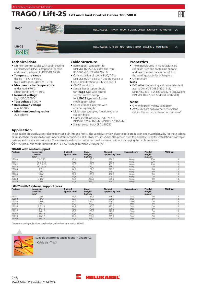
TRAGO / Lift-2S Lift and Hoist Control Cables 300/500 V
PropertiesCable structureTechnical dataBare copper-conductor, toDIN VDE 0295 cl.6, extra fine-wire,BS 6360 cl.6, IEC 60228 cl.6
Lift hoist control cables with strain bearingelement Special PVC-compound for coreand sheath, adapted to DIN VDE 0250
The materials used in manufacture arecadmium-free and contain no siliconeand free from substances harmful tothe wetting properties of lacquersTemperature range
flexing -15°C to +70°Cfixed installation -40°C to +70°C
Core insualtion of special PVC, TI2 toDIN VDE 0207-363-3 / DIN EN 50363-3 UV-resistant
TestsCore identification to DIN VDE 0293Max. conductor temperatureunder load +70°Ccircuit conditions +150°C
GN-YE conductor PVC self-extinguishing and flame retardantacc. to DIN VDE 0482-332-1-2,DIN EN 60332-1-2, IEC 60332-1 (equivalentDIN VDE 0472 part 804 test method B)
Special hemp support braidfor Trago type with centralsupport core of hempfor Lift-2S type with 2 outersteel support wires
Nominal voltageU0/U 300/500 V
NoteTest voltage 3000 VBreakdown voltagemin. 6000 V
Cores stranded in layers withoptimal lay-length
G = with green-yellow conductorAWG sizes are approximate equivalentvalues. The actual cross-section is in mm².Multi-layer wrapping functioning as a
support braidMinimum bending radius20x cable Ø
Outer sheath of special PVC TM2 toDIN VDE 0207-363-4-1/DIN EN 50363-4-1Sheath colour black (RAL 9005)
ApplicationThese cables are used as control or feeder cables in lifts and hoists. The special attention given to both production and material quality for these cableshas made them ideal even for use under extreme conditions. HELUKABEL®-Lift-2S has also proven itself to be ideally suited for installation in conveyorsystems and manual control units. The external steel support wires can be dismounted without damaging the cable insulation.
= The product is conformed with the EC Low-Voltage Directive 2006/95/EC.
TRAGO with central supportAWG-No.Pendal
lengthmax. m
Support coreWeightapprox. kg / km
Cop.weightkg / km
Outer Øapprox. mm
No.cores xcross-sec.mm²
Part no.
19250Hemp290,050,015,47 G 0,752508019220Hemp360,086,019,212 G 0,752508119110Hemp455,0130,021,018 G 0,75250821990Hemp535,0173,023,024 G 0,75250831880Hemp222,067,014,97 G 1250841880Hemp415,0115,020,012 G 1250851870Hemp450,0173,021,418 G 1250861870Hemp490,0192,021,620 G 1250871860Hemp605,0230,023,224 G 1250881890Hemp950,0346,026,136 G 125089
Lift-2S with 2 external support coresAWG-No.Pendal
lengthmax. m
Support coreWeightapprox. kg / km
Cop.weightkg / km
Outer Øapprox. mm
No.cores xcross-sec.mm²
Part no.
1850Steel446,0115,213,512 G 1250911850Steel528,0172,816,218 G 1250921850Steel660,0240,019,025 G 1250931850Steel760,0288,021,930 G 1250941650Steel425,0115,014,78 G 1,5250951650Steel505,0172,816,012 G 1,5250961650Steel575,0230,019,515 G 1,5250971650Steel640,0259,019,318 G 1,5250981650Steel715,0288,019,520 G 1,5250991650Steel820,0346,022,524 G 1,525100
Dimensions and specifications may be changed without prior notice. (RF01)
248
Allweather, Rubber and Liftcables
Suitable accessories can be found in Chapter X.
• Cable tie - T-WS
CW&A Edition 27 (published 01.04.2015)

Bauliftkabel B101 / B102 / B103 to be used at plant elevators
PropertiesCable structureTechnical dataBare copper-conductor, extra fine-wire,high flexible
Temperature rangeflexing -10°C to +80°C
Sheath UV-resistantIn carriage version with special supportbraiding and with PUR sheath particularlyresistant to wear, oil, hydrolysis andmicrobial attack
Core insulation of plastic,flexible at low temperatures
Nominal voltagecontrol cores 300/500 Vpower supply cores 0,6/1 kV Core identification black cores with
continuous white numberingA.c. test voltage, 50 Hzcontrol cores 1500 Vpower supply cores 3000 V
NoteGN-YE conductor
Outer sheath of special plastic,flexible at low temperatures
Optional separate copper screeningof the control coresMinimum bending radius
10x cable Ø Sheath colour black
ApplicationThese hybrid cables are used for power supply and control of vertical lifts in the construction industry. There are 3 cable versions.Bauliftkabel B101: Here the cable is drawn vertically from a drum as a drag cable via the load platform. The load platform pulls the cable along asit moves up. During the downwards motion the cable returns to the drum automatically. Our special versions are used at heights of up to about 150m.Bauliftkabel B102: For greater heights, a so-called carriage version is employed, in which the cable is fed at the centre of the tower, i. e. half theway up.Bauliftkabel B103: Here the cable is guided via a spring-loaded drum. These vertical construction lifts are used during new construction andrenovation work on high buildings. The rack lattice elements are fastened at intervals to the exterior facade.
= The product is conformed with the EC Low-Voltage Directive 2006/95/EC.
Bauliftkabel B102Bauliftkabel B101AWG-No.Weight
approx.kg / km
Cop.weightkg / km
Outer Øapprox.mm
No.cores xcross-sec.mm²
Part no. AWG-No.Weightapprox.kg / km
Cop.weightkg / km
Outer Øapprox.mm
No.cores xcross-sec.mm²
Part no.
-306,0220,020,05 G 2,5 + 10 x 1,073519 61080,0830,028,54 G 16 + 1 x 2,5 + 2 x 2 x 1,07429361080,0787,028,54 G 16 + 1 x 2,5 + 2 x 2 x 1,07467014320,0225,620,05 G 2,5 + 11 x 1,07391341500,01176,033,44 G 25 + 1 x 2,5 + 2 x 2 x 1,07429712360,0184,017,43 G 4 + 7 x 1,07040221850,01500,038,04 G 35 + 4 x 2,5 + 2 x 2 x 1,0
+ 1 x 1,07812210555,0330,020,54 G 6 + 9 x 1,070931
10575,0340,021,04 G 6 + 10 x 1,07037710625,0388,022,04 G 6 + 15 x 1,071901
Bauliftkabel B1038870,0480,025,04 G 10 + 10 x 1,07136961250,0700,026,14 G 16 + 6 x 1,078123 AWG-No.Weight
approx.kg / km
Cop.weightkg / km
Outer Øapprox.mm
No.cores xcross-sec.mm²
Part no.61300,0710,029,04 G 16 + 10 x 1,07812461380,0760,031,54 G 16 + 15 x 1,07812561460,0830,028,54 G 16 + 1 x 2,5 + 4 x 1,073726 14230,0125,013,04 G 2,5 + 3 x 1,077532
14280,0125,015,34 G 2,5 + 3 x 1,077538
Dimensions and specifications may be changed without prior notice.
249
Allweather, Rubber and Liftcables
F
Suitable accessories can be found in Chapter X.
• Cable tie - T-WS
CW&A Edition 27 (published 01.04.2015)
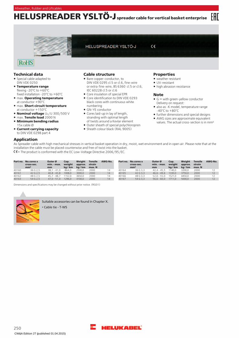
HELUSPREADER YSLTÖ-J spreader cable for vertical basket enterprise
PropertiesCable structureTechnical dataBare copper-conductor, toDIN VDE 0295 cl.5 or cl.6, fine-wireor extra-fine-wire, BS 6360 cl.5 or cl.6,IEC 60228 cl.5 or cl.6
Special cable adapted toDIN VDE 0250
weather resistantUV-resistant
Temperature rangeflexing -20°C to +60°Cfixed installation -20°C to +60°C
high abrasion resistance NoteCore insulation of special EPR
max. Operating temperatureat conductor +90°C
Core identification to DIN VDE 0293black cores with continuous whitenumbering
G = with green-yellow conductorDelivery on request:
max. Short circuit temperatureat conductor +150°C
also as -K model, temperature range-40°C to +80°CGN-YE conductor
Nominal voltage U0/U 300/500 V Cores laid-up in lay of length,stranding with optimal lengthof twists around a Kevlar element
further dimensions and special designsmax. Tensile load 2000 N AWG sizes are approximate equivalent
values. The actual cross-section is in mm²Minimum bending radius15x cable Ø Outer sheath of special polychloropren
Sheath colour black (RAL 9005)Current carrying capacityto DIN VDE 0298 part 4
ApplicationAs Spreader cable with high mechanical stresses in vertical basket operation in dry, moist, wet environment and in open air. Please note that at theinstallation the cable must be placed counterwise and free of twist into the basket.
= The product is conformed with the EC Low-Voltage Directive 2006/95/EC.
AWG-No.Tensile
strainmax. N
Weightapprox.kg / km
Cop.weightkg / km
Outer Ømin. - max.mm
No.cores xcross-sec.mm²
Part no. AWG-No.Tensilestrainmax. N
Weightapprox.kg / km
Cop.weightkg / km
Outer Ømin. - max.mm
No.cores xcross-sec.mm²
Part no.
1420002500,0864,038,1 - 41,036 G 2,540160 1220003200,01140,042,4 - 45,536 G 3,3401641220003750,01330,046,6 - 49,642 G 3,3401651420003000,01008,040,8 - 43,842 G 2,540161
1420003650,01152,045,7 - 48,748 G 2,540162 1220004450,01521,052,0 - 55,048 G 3,3401661220005000,01711,056,6 - 60,054 G 3,3401671420004100,01296,047,0 - 51,054 G 2,540163
Dimensions and specifications may be changed without prior notice. (RG01)
250
Allweather, Rubber and Liftcables
Suitable accessories can be found in Chapter X.
• Cable tie - T-WS
CW&A Edition 27 (published 01.04.2015)

CW&A Edition 27 (published 01.04.2015)


