

Section 7: Connectors & Heat Shrink

www.tvcinc.com
Section 7: Connectors & Heat Shrink
Table of Contents
(888)644-60757 - 2
T&B LRC
• Adaptors & Terminators ................................................... 7 - 3
• Attenuator Pads ............................................................... 7 - 12
• Entry Connectors ............................................................. 7 - 13
• F Series Adaptors ............................................................ 7 - 17
• F Series Female Connectors ........................................... 7 - 19
• F Series Male Connectors ............................................... 7 - 20
• F Series Terminators ....................................................... 7 - 22
• Ground Blocks ................................................................. 7 - 25
• Snap-N-Seal .................................................................... 7 - 26
Corning
• F Connectors ................................................................... 7 - 29
• F Connectors Accessories ............................................... 7 - 31
• G2 Series Connectors ..................................................... 7 - 36
• GRS Series Connectors .................................................. 7 - 39
• Trunk & Distribution Products .......................................... 7 - 44
Canusa
• Heat Shrink ...................................................................... 7 – 51
Tyco
• Heat Shrink ...................................................................... 7 – 54

www.tvcinc.com
Section 7: Connectors & Heat Shrink
Adaptors & Terminators
(888)644-60757 - 3
Cable Group Chart
Manufacturer Cable Types
CCS Hatfield GID I*, Chema Foam*
Cerro GX™*, Polyethylene™*
CommScope Parameter l® *, Alumagard®*
Systems 11& 12*, 21 &22*
Times Alumifoam®*, Alumifoam II®*
Cerro Cerrofoam™*
CommScope Cell-O-Air®*
Times Dynafoam™*, Dynaplus™*
General Cable Fused Disc I™*,II™*
CommScope Parameter II®*
CCS Hatfield GID Ill*
Cerro GXX™*
CommScope Parameter III
Scientific Atlanta GID Ill*
Systems 31 & 32*
TimesAlumifoam III™*,
T4™,T4+™, T6™ ,T10™
Capscan 4*
Scientific Atlanta Cable Flex
Times TX™
CommScope Quantum Reach®
Trilogy MC2
General Cable Fused
General Cable Fused Disc Metric Ill™*
Cable Group J
Cable Group K
Cable Group G
Cable Group E
Cable Group F
Cable Group H
Cable Group I
Cable Group A
Cable Group B
Cable Group C
Cable Group D
Three Piece AdaptorTwo Piece Cable To “F” Female Adaptor Bulkhead
Bulkhead connector capable
of being secured in place for
permanent mounting.
A B
BI412FFK A .080 .412 13/16 7/8
BI412FFK3 E,J .092 .412 13/16 7/8
BI440FFMC I .105 .450 1 1
BI500FFK A .100 .500 1 1
BI500FFK3 E,J .109 .500 1 1
BI500FFMC I .123 .510 1 1
BI500FFQR H .117 .580 1 1
BI540FFQR H .124 .610 1 1
BI565FFTX G .129 .565 1 1
BI625FFK3 E .137 .625 1 1
BI650FFMC I .156 .640 1-1/8 1-1/8
BI700FFTX G .163 .703 1-1/8 1-1/8
BI715FFQR H .166 .785 1-3/16 1-3/16
BI750FFK A .148 .750 1-1/8 1-1/8
BI750FFK3 E .167 .750 1-1/8 1-1/8
BI750FFMC I .185 .760 1-1/8 1-1/8
BI840FFTX G .194 .840 1-3/8 1-3/8
BI860FFQR H .203 .960 1-1/2 1-1/2
BI875FFK3 E .194 .875 1-3/8 1-3/8
BI1000FFK3 E .220 1.000 1-1/2 1-1/2
BI1000FFMC I .248 1.015 1-1/2 1-1/2
BI1125FFQR H .263 1.225 1-3/4 1-3/4
BI1160FFTX G .269 1.160 1-3/4 1-3/4
DimensionPart
Number
Cable
Group
(*)
Center
Cond.
Cable
O.D.
www.tvcinc.com
Section 7: Connectors & Heat Shrink
Adaptors & Terminators
(888)644-60757 - 4
(*) Cable Group Chart
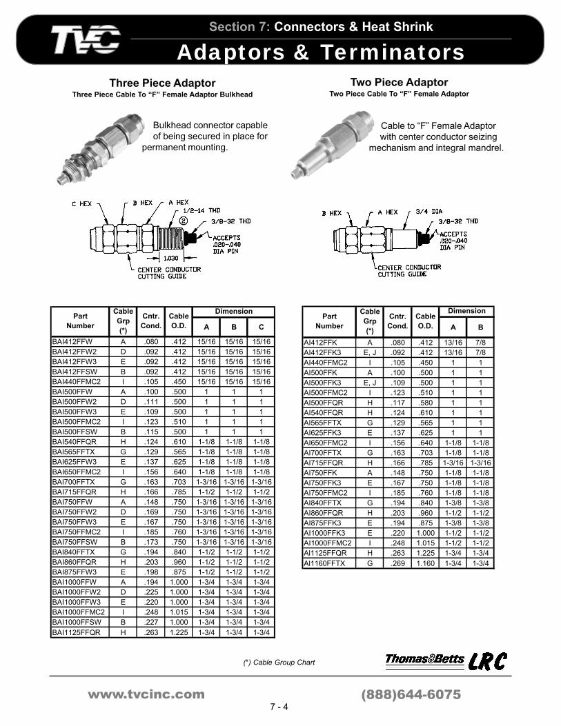
Three Piece AdaptorThree Piece Cable To “F” Female Adaptor Bulkhead
Bulkhead connector capable
of being secured in place for
permanent mounting.
A B C
BAI412FFW A .080 .412 15/16 15/16 15/16
BAI412FFW2 D .092 .412 15/16 15/16 15/16
BAI412FFW3 E .092 .412 15/16 15/16 15/16
BAI412FFSW B .092 .412 15/16 15/16 15/16
BAI440FFMC2 I .105 .450 15/16 15/16 15/16
BAI500FFW A .100 .500 1 1 1
BAI500FFW2 D .111 .500 1 1 1
BAI500FFW3 E .109 .500 1 1 1
BAI500FFMC2 I .123 .510 1 1 1
BAI500FFSW B .115 .500 1 1 1
BAI540FFQR H .124 .610 1-1/8 1-1/8 1-1/8
BAI565FFTX G .129 .565 1-1/8 1-1/8 1-1/8
BAI625FFW3 E .137 .625 1-1/8 1-1/8 1-1/8
BAI650FFMC2 I .156 .640 1-1/8 1-1/8 1-1/8
BAI700FFTX G .163 .703 1-3/16 1-3/16 1-3/16
BAI715FFQR H .166 .785 1-1/2 1-1/2 1-1/2
BAI750FFW A .148 .750 1-3/16 1-3/16 1-3/16
BAI750FFW2 D .169 .750 1-3/16 1-3/16 1-3/16
BAI750FFW3 E .167 .750 1-3/16 1-3/16 1-3/16
BAI750FFMC2 I .185 .760 1-3/16 1-3/16 1-3/16
BAI750FFSW B .173 .750 1-3/16 1-3/16 1-3/16
BAI840FFTX G .194 .840 1-1/2 1-1/2 1-1/2
BAI860FFQR H .203 .960 1-1/2 1-1/2 1-1/2
BAI875FFW3 E .198 .875 1-1/2 1-1/2 1-1/2
BAI1000FFW A .194 1.000 1-3/4 1-3/4 1-3/4
BAI1000FFW2 D .225 1.000 1-3/4 1-3/4 1-3/4
BAI1000FFW3 E .220 1.000 1-3/4 1-3/4 1-3/4
BAI1000FFMC2 I .248 1.015 1-3/4 1-3/4 1-3/4
BAI1000FFSW B .227 1.000 1-3/4 1-3/4 1-3/4
BAI1125FFQR H .263 1.225 1-3/4 1-3/4 1-3/4
Cable
O.D.
DimensionPart
Number
Cable
Grp
(*)
Cntr.
Cond.
Two Piece AdaptorTwo Piece Cable To “F” Female Adaptor
Cable to “F” Female Adaptor
with center conductor seizing
mechanism and integral mandrel.
A B
AI412FFK A .080 .412 13/16 7/8
AI412FFK3 E, J .092 .412 13/16 7/8
AI440FFMC2 I .105 .450 1 1
AI500FFK A .100 .500 1 1
AI500FFK3 E, J .109 .500 1 1
AI500FFMC2 I .123 .510 1 1
AI500FFQR H .117 .580 1 1
AI540FFQR H .124 .610 1 1
AI565FFTX G .129 .565 1 1
AI625FFK3 E .137 .625 1 1
AI650FFMC2 I .156 .640 1-1/8 1-1/8
AI700FFTX G .163 .703 1-1/8 1-1/8
AI715FFQR H .166 .785 1-3/16 1-3/16
AI750FFK A .148 .750 1-1/8 1-1/8
AI750FFK3 E .167 .750 1-1/8 1-1/8
AI750FFMC2 I .185 .760 1-1/8 1-1/8
AI840FFTX G .194 .840 1-3/8 1-3/8
AI860FFQR H .203 .960 1-1/2 1-1/2
AI875FFK3 E .194 .875 1-3/8 1-3/8
AI1000FFK3 E .220 1.000 1-1/2 1-1/2
AI1000FFMC2 I .248 1.015 1-1/2 1-1/2
Al1125FFQR H .263 1.225 1-3/4 1-3/4
Al1160FFTX G .269 1.160 1-3/4 1-3/4
Cable
O.D.
DimensionPart
Number
Cable
Grp
(*)
Cntr.
Cond.

www.tvcinc.com
Section 7: Connectors & Heat Shrink
Adaptors & Terminators
(888)644-60757 - 5
(*) Cable Group Chart
Three Piece AdaptorThree Piece Cable To “F” Female Adaptor
Two Piece AdaptorTwo Piece Cable To “F” Male Adaptor
Cable to “F” Female Adaptor
with center conductor seizing
mechanism and integral
mandrel.
A B C
AI412FFW A .080 .412 15/16 15/16 15/16
AI412FFW2 D .092 .412 15/16 15/16 15/16
AI412FFW3 E .092 .412 15/16 15/16 15/16
AI412FFSW B .092 .412 15/16 15/16 15/16
AI440FFWMC2 I .105 .450 15/16 15/16 15/16
AI500FFW A .100 .500 1 1 1
AI500FFW2 D .111 .500 1 1 1
AI500FFW3 E .109 .500 1 1 1
AI500FFWMC2 I .123 .510 1 1 1
AI500FFSW B .115 .500 1 1 1
AI540FFWQR H .124 .610 1-1/8 1-1/8 1-1/8
AI565FFWTX G .129 .565 1-1/8 1-1/8 1-1/8
AI625FFW3 E .137 .625 1-1/8 1-1/8 1-1/8
AI650FFWMC2 I .156 .640 1-1/8 1-1/8 1-1/8
AI700FFWTX G .163 .703 1-3/16 1-3/16 1-3/16
AI715FFWQR H .166 .785 1-1/2 1-1/2 1-1/2
AI750FFW A .148 .750 1-3/16 1-3/16 1-3/16
AI750FFW2 D .169 .750 1-3/16 1-3/16 1-3/16
AI750FFW3 E .167 .750 1-3/16 1-3/16 1-3/16
AI750FFWMC2 I .185 .760 1-3/16 1-3/16 1-3/16
AI750FFSW B .173 .750 1-3/16 1-3/16 1-3/16
AI840FFWTX G .194 .840 1-1/2 1-1/2 1-1/2
AI860FFWQR H .203 .960 1-1/2 1-1/2 1-1/2
AI875FFW3 E .194 .875 1-1/2 1-1/2 1-1/2
AI1000FFW A .193 1.000 1-3/4 1-3/4 1-3/4
AI1000FFW2 D .225 1.000 1-3/4 1-3/4 1-3/4
AI1000FFW3 E .220 1.000 1-3/4 1-3/4 1-3/4
AI100FFWMC2 I .248 1.015 1-3/4 1-3/4 1-3/4
AI1000FFSW B .227 1.000 1-3/4 1-3/4 1-3/4
Al1125FFWQR H .263 1.225 1-3/4 1-3/4 1-3/4
DimensionPart
Number
Cable
Grp
(*)
Cntr.
Cond.
Cable
O.D.
Cable to “F” Male Adaptor with
center conductor seizing
mechanism and integral
mandrel.
A B
AI412FMK A .080 .412 13/16 7/8
AI412FMK3 E, J .092 .412 13/16 7/8
AI440FMMC2 I .105 .450 1 1
AI500FMK A .100 .500 1 1
AI500FMK3 E, J .109 .500 1 1
AI500FMMC2 I .123 .510 1 1
AI500FMQR H .117 .580 1 1
AI540FMQR H .124 .610 1 1
AI565FMTX G .129 .565 1 1
AI625FMK3 E .137 .625 1 1
AI650FMMC2 I .156 .640 1-1/8 1-1/8
AI700FMTX G .163 .703 1-1/8 1-1/8
AI715FMQR H .166 .785 1-3/16 1-3/16
AI750FMK A .148 .750 1-1/8 1-1/8
AI750FMK3 E .167 .750 1-1/8 1-1/8
AI750FMMC2 I .185 .760 1-1/8 1-1/8
AI840FMTX G .194 .840 1-3/8 1-3/8
AI860FMQR H .203 .960 1-1/2 1-1/2
AI875FMK3 E .194 .875 1-3/8 1-3/8
AI1000FMK3 E .220 1.000 1-1/2 1-1/2
AI1000FMMC2 I .248 1.015 1-1/2 1-1/2
AI1125FMQR H .263 1.225 1-3/4 1-3/4
AI1160FMTX G .269 1.160 1-3/4 1-3/4
Cable
O.D.
DimensionPart
Number
Cable
Grp
(*)
Cntr.
Cond.

www.tvcinc.com
Section 7: Connectors & Heat Shrink
Adaptors & Terminators
(888)644-60757 - 6
(*) Cable Group Chart
Three Piece AdaptorThree Piece Cable To “F” Male Adaptor
Two Piece Cable Adaptor
A B C
AI412FMW A .080 .412 15/16 15/16 15/16
AI412FMW2 D .092 .412 15/16 15/16 15/16
AI412FMW3 E .092 .412 15/16 15/16 15/16
AI440FMWMC2 I .105 .450 15/16 15/16 15/16
AI412FMSW B .092 .412 15/16 15/16 15/16
AI500FMW A .100 .500 1 1 1
AI500FMW2 D .111 .500 1 1 1
AI500FMW3 E .109 .500 1 1 1
AI500FMWMC2 I .123 .510 1 1 1
AI500FMSW B .115 .500 1 1 1
AI540FMWQR H .124 .610 1-1/8 1-1/8 1-1/8
AI565FMWTX G .129 .565 1-1/8 1-1/8 1-1/8
AI625FMW3 E .137 .625 1-1/8 1-1/8 1-1/8
AI650FMWMC2 I .156 .640 1-1/8 1-1/8 1-1/8
AI700FMWTX G .163 .703 1-3/16 1-3/16 1-3/16
AI715FMWQR H .166 .785 1-1/2 1-1/2 1-1/2
AI750FMW A .148 .750 1-3/16 1-3/16 1-3/16
AI750FMW2 D .169 .750 1-3/16 1-3/16 1-3/16
AI750FMW3 E .167 .750 1-3/16 1-3/16 1-3/16
AI750FMWMC2 I .185 .760 1-3/16 1-3/16 1-3/16
AI750FMSW B .173 .750 1-3/16 1-3/16 1-3/16
AI840FMWTX G .194 .840 1-1/2 1-1/2 1-1/2
AI860FMWQR H .203 .960 1-1/2 1-1/2 1-1/2
AI875FMW3 E .194 .875 1-1/2 1-1/2 1-1/2
AI1000FMW A .193 1.000 1-3/4 1-3/4 1-3/4
Al1000FMW2 D .225 1.000 1-3/4 1-3/4 1-3/4
AI1000FMW3 E .220 1.000 1-3/4 1-3/4 1-3/4
AI1000FMMC2 I .248 1.015 1-3/4 1-3/4 1-3/4
AI1000FMSW B .227 1.000 1-3/4 1-3/4 1-3/4
AI1125FMQR H .263 1.225 1-3/4 1-3/4 1-3/4
DimensionPart
Number
Cable
Grp
(*)
Cntr.
Cond.
Cable
O.D.
Cable to “F” Male Adaptor with
center conductor seizing
mechanism and integral mandrel.
Terminates RF signals and
blocks 60 Hz AC power.
A B
AI412TRBK A .080 .412 13/16 7/8
AI412TRBK3 E, J .092 .412 13/16 7/8
AI440TRBMC2 I .105 .450 1 1
AI500TRBK A .100 .500 1 1
AI500TRBK3 E, J .109 .500 1 1
AI500TRBMC2 I .123 .510 1 1
AI500TRBQR H .117 .580 1 1
AI540TRBQR H .124 .610 1 1
AI565TRBTX G .129 .565 1 1
AI625TRBK3 E .137 .625 1 1
AI650TRBMC2 I .156 .640 1-1/8 1-1/8
AI700TRBTX G .163 .703 1-1/8 1-1/8
AI715TRBQR H .166 .785 1-3/16 1-3/16
AI750TRBK A .148 .750 1-1/8 1-1/8
AI750TRBK3 E .167 .750 1-1/8 1-1/8
AI750TRBMC2 I .185 .760 1-1/8 1-1/8
AI840TRBTX G .194 .840 1-3/8 1-3/8
AI860TRBQR H .203 .960 1-1/2 1-1/2
AI875TRBK3 E .194 .875 1-3/8 1-3/8
AI1000TRBK3 E .220 1.000 1-1/2 1-1/2
AI1000TRBMC2 I .248 1.015 1-1/2 1-1/2
AI1125TRBQR H .263 1.225 1-3/4 1-3/4
Cable
O.D.
DimensionPart
Number
Cable
Grp
(*)
Cntr.
Cond.

www.tvcinc.com
Section 7: Connectors & Heat Shrink
Adaptors & Terminators
(888)644-60757 - 7
(*) Cable Group Chart
Three Piece Cable Adaptor Two Piece Cable AdaptorTwo Piece Cable To “N” Or “UHF” Adaptor
Terminates RF signals and
blocks 60 Hz AC power.
A B C
AI412TRBW A .080 .412 15/16 15/16 15/16
AI412TRBW2 D .092 .412 15/16 15/16 15/16
AI412TRBW3 E .092 .412 15/16 15/16 15/16
AI412TRBSW B .092 .412 15/16 15/16 15/16
AI440TRBWMC2 I .105 .450 15/16 15/16 15/16
AI500TRBW A .100 .500 1 1 1
AI500TRBW2 D .111 .500 1 1 1
AI500TRBW3 E .109 .500 1 1 1
AI500TRBWMC2 I .123 .510 1 1 1
AI500TRBSW B .115 .500 1 1 1
AI540TRBWQR H .124 .610 1-1/8 1-1/8 1-1/8
AI565TRBWTX G .129 .565 1-1/8 1-1/8 1-1/8
AI625TRBW3 E .137 .625 1-1/8 1-1/8 1-1/8
AI650TRBWMC2 I .156 .640 1-1/8 1-1/8 1-1/8
AI700TRBWTX G .163 .703 1-3/16 1-3/16 1-3/16
AI715TRBWQR H .166 .785 1-1/2 1-1/2 1-1/2
AI750TRBW A .148 .750 1-3/16 1-3/16 1-3/16
AI750TRBW2 D .169 .750 1-3/16 1-3/16 1-3/16
AI750TRBW3 E .167 .750 1-3/16 1-3/16 1-3/16
AI750TRBWMC2 I .185 .760 1-3/16 1-3/16 1-3/16
AI750TRBSW B .173 .750 1-3/16 1-3/16 1-3/16
AI840TRBWTX G .194 .840 1-1/2 1-1/2 1-1/2
AI860TRBWQR H .203 .960 1-1/2 1-1/2 1-1/2
AI875TRBW3 E .194 .875 1-1/2 1-1/2 1-1/2
AI1000TRBW A .193 1.000 1-3/4 1-3/4 1-3/4
AI1000TRBW2 D .225 1.000 1-3/4 1-3/4 1-3/4
AI1000TRBW3 E .226 1.000 1-3/4 1-3/4 1-3/4
AI1000TRBWMC2 I .248 1.015 1-3/4 1-3/4 1-3/4
AI1000TRBSW B .227 1.000 1-3/4 1-3/4 1-3/4
AI1125TRBWQR H .263 1.225 1-3/4 1-3/4 1-3/4
DimensionPart
Number
Cable
Grp
(*)
Cntr.
Cond.
Cable
O.D.
Cable to “N” Male Adaptor with center
conductor seizing mechanism and
mandrel. Cable to “N” and “UHF”
Adaptors are available by contacting your
TVC Customer Service Representative.
“N” Male Adaptor
75 ohm Interface(also Available with 50 ohm Interface)
“N” Female Adaptor
75 ohm Interface(also Available with 50 ohm Interface)
“UHF” Male Adaptor
50 ohm Interface(also Available with 75 ohm Interface)
“UHF” Female Adaptor
50 ohm Interface
(also Available with 75 ohm Interface)

www.tvcinc.com
Section 7: Connectors & Heat Shrink
Adaptors & Terminators
(888)644-60757 - 8
Three Piece Cable To “N”
Or “UHF” Adaptor
Cable to “N” Male Adaptor with
center conductor seizing
mechanism and mandrel. Cable
to “N” and “UHF” Adaptors are
available by contacting your TVC
Customer Service Representative.
“N” Male Adaptor
75 ohm Interface(also Available with 50 ohm Interface)
“N”Female Adaptor
75 ohm Interface(also Available with 50 ohm Interface)
“UHF” Male Adaptor
50 ohm Interface(also Available with 75 ohm Interface)
“UHF” Female Adaptor
50 ohm Interface(also Available with 75 ohm Interface)
Alluminum Products
P/N Description
EMI11 Entry, Feed Thru Connector, 11 Series
5/8" -24 Entry to Series 11 - Crimp On
P/N Post I.D. Collar I.D. Crimp Sz Tool
ECR11 .295 .477 .470 1,2
5/8" -24 Entry to Series 11 - Crimp On
Tool: 1)CT611QS 2) CT214
P/N Description Dim. A
F625E “F” Female .806
F625BE “F” Female (AC Block) .951
KF625E* “F” Female 1 GHz .941
5/8" - 24 Entry to "F" Female
P/N Termination Description
625TRB 75 ohm AC Blocking Feature
Housing Terminator
P/N Termination Description
TRFS 75 ohm —
TRBF 75 ohm AC Blocking Feature
Terminator
5/8” - 24 Female to “F” FemaleP/N - BAFF

www.tvcinc.com
Section 7: Connectors & Heat Shrink
Adaptors & Terminators
(888)644-60757 - 9
Housing to housing
Adaptors eliminate the
need for jumpers and allow
cascading of equipment.
Entry to Entry Adaptor
Part Number ................. ETE625
Entry to Entry Adaptor - Rotational
Dimension A ................. ETE625R
Dimension A ................. ETE6253
Dimension A
Entry to Entry Adaptor - Locking Rotational
Part Number ................. ETE625LR
Housing splice blocks allow
through splicing, right angle turns
and inline pedestal turns of two
connectors. Through splice blocks
allow through splicing of two
connectors only. Both can be used for
splicing like or different sized cable.
Through Splice Block
Part Number ................. TSB
5/8” - 24 Male to Female Adaptor, Auto Seize
Part Number ................. KSFAS
Housing Splice Block
HSB
HSBGD ........................ Grounding Lug Feature

www.tvcinc.com
Section 7: Connectors & Heat Shrink
Adaptors & Terminators
(888)644-60757 - 10
Right angle connectors are
designed for applications
where space restrictions
exist such as pedestals or
where tight bends are required.
Right Angle Adaptor - Rotational
EU90R .......................... A = 2.305
EU903R ........................ A = 5.420
Right Angle Adaptor: Auto Seize (Screwless)
Part Number ................. EU90AS
Part Number ................. EU180AS
180º Adaptor - Auto Seize (Screwless)
Entry Extension
EXT175 ........................ A = 1.750
EXT42 .......................... A = 4.000
EXT66 .......................... A = 6.250
EXT90 .......................... A = 8.500
180º Adaptor
EU180 .......................... A = 1.990
EU18030 ...................... A = 3.270
EU18045 ...................... A = 4.265
Entry Adaptor: Auto Seize (Screwless)
EXTAS3 ........................ Precision, Auto Seize Ext, 3”
EXTAS6 ........................ Precision, Auto Seize Ext, 6”
5/8” - 24 Male to Female Adaptor, Rotational
KSMASR ...................... A = 1.822 (46) B = 2.132 (54)
KSMASRC.................... A = .740 (19) B = 1.051 (27)
Right Angle Adaptor
EU90 ............................ A = 1.185
EU903 .......................... A = 2.435
EU9045 ........................ A = 3.435
EU906 .......................... A = 5.685

www.tvcinc.com
Section 7: Connectors & Heat Shrink
Adaptors & Terminators
(888)644-60757 - 11
Plug Adaptors
A variety of replacement plugs and caps for equipment and connector Adaptors
are available.
5/8” - 24 Adaptor
KS625........................................Adaptor, 13-16 - 20 to 5/8 - 24
Plug
115642 .......................................Distribution Amplifier Plug
Plug
A B C
625P A Plug with "O" Ring 3/4 5/8 - 24 .400
625HP B Plug with "O" Ring 3/4 5/8 - 24 .360
750P A Plug, Hex with "O" Ring 7/8 3/4 - 24 .345
750P A Plug, Hex with "O"ring 7/8 3/4 - 24 .345
P/N Fig. DescriptionDimension

www.tvcinc.com
Section 7: Connectors & Heat Shrink
Attenuator Pads
(888)644-60757 - 12
Attenuator Pads
Attenuator pads for applications where attenuation of signal is required.
AP1FF 1 dB
AP3FF 3 dB
AP6FF 6 dB
AP10FF 10 dB
AP20FF 20 dB
Part
NumberAttenuation
Male to Male
AP1FM 1dB
AP3FM 3dB
AP6FM 6dB
AP10FM 10dB
AP20FM 20dB
AP30FM 30dB
Male to Female
Part
NumberAttenuation
Part
Number
Band Reject
Attenuation
Band Pass
Insertion Loss
HP1 0-3 MHz > 35 dB 50 MHz - 1GHz < 1 dB
High Pass Filter

www.tvcinc.com
Section 7: Connectors & Heat Shrink
Entry Connectors
(888)644-60757 - 13
Cable Group Chart Feed Through Integral Mandrel
Used for connecting cable to
equipment. Center conductor of
cable is seized inside
equipment. Integral mandrel for
excellent RF shielding.
A B C
F81 A Splice .460 .345 .955
F81BE† A AC Blocking 1.038 .312 1.475
F81D A Single D Flat .376 .429 .955
F81DF A Double D Flat .460 .345 .955
F81HDW† A W/Mounting .460 .345 .955
F81LS C Long Body .500 .490 1.390
F81PM† B Panel Mount Splice .735 .490 1.390
KF81 A Precision Splice* .580 .278 .958
KF81PM† B Precision Panel Mount* .735 .510 1.380
†Mounting hadware inlcuded *Accepts .032-.040 dia. Pin
Part
NumberDescriptionFig.
Dimension
A B
EMI412Pl A .080 .412 15/16 15/16
EMI412P2 D .092 .412 15/16 15/16
EMI412P3 E,J .092 .412 15/16 15/16
EMI412S B .092 .412 15/16 15/16
EMI440MC2 I .105 .450 13/16 7/8
EMI500MC2 I .123 .510 1 1
EMI500PI A .100 .500 1 1
EMI50OP2 D,J .111 .500 1 1
EMI50OP3 E .109 .500 1 1
EMI500S B .111 .500 1 1
EMI500QR H .117 .580 1 1
EMI540QR H .124 .610 1 1
EMI565TX G .129 .565 1 1
EMI625K3 E .137 .625 1-1/8 1-1/8
EMI650MC2 I .156 .640 1-1/8 1-1/8
DimensionPart
Number
Cable
Group(*)
Center
Cond.
Cable
O.D.
(*) Cable Group Chart
Manufacturer Cable Types
CCS Hatfield GID I*, Chema Foam*
Cerro GX™*, Polyethylene™*
CommScope Parameter l® *, Alumagard®*
Systems 11& 12*, 21 &22*
Times Alumifoam®*, Alumifoam II®*
Cerro Cerrofoam™*
CommScope Cell-O-Air®*
Times Dynafoam™*, Dynaplus™*
General Cable Fused Disc I™*,II™*
CommScope Parameter II®*
CCS Hatfield GID Ill*
Cerro GXX™*
CommScope Parameter III
Scientific Atlanta GID Ill*
Systems 31 & 32*
TimesAlumifoam III™*,
T4™,T4+™, T6™ ,T10™
Capscan 4*
Scientific Atlanta Cable Flex
Times TX™
CommScope Quantum Reach®
Trilogy MC2
General Cable Fused
General Cable Fused Disc Metric Ill™*
Cable Group J
Cable Group K
Cable Group G
Cable Group E
Cable Group F
Cable Group H
Cable Group I
Cable Group A
Cable Group B
Cable Group C
Cable Group D

www.tvcinc.com
Section 7: Connectors & Heat Shrink
Entry Connectors
(888)644-60757 - 14
(*) Cable Group Chart
Two Piece Splice
Used to join two ends of
the same type of cable
together. Center conductor
seizing mechanism and gripping
of aluminum sheath activated by
tightening the back nut.
A B
SI412K A .080 .412 13/16 7/8
SI412K3 E,J .092 .412 13/16 7/8
SI440MC2 I .105 .450 7/8 7/8
SI500K A .100 .500 1 1
SI500K3 E,J .109 .500 1 1
SI500MC2 I .123 .510 1 1
SI500QR H .117 .580 1 1
SI540QR H .124 .610 1 1
SI565TX G .129 .565 1 1
SI625K3 E .137 .625 1 1
SI650MC2 I .156 .640 1-1/8 1-1/8
SI700TX G .163 .703 1-1/8 1-1/8
SI715QR H .166 .785 1-3/16 1-3/16
SI750K A .148 .750 1-1/8 1-1/8
SI750K3 E .167 .750 1-1/8 1-1/8
SI750MC2 I .185 .760 1-1/8 1-1/8
SI840TX G .194 .840 1-3/8 1-3/8
SI860QR H .203 .960 1-1/2 1-1/2
SI875K3 E .194 .875 1-3/8 1-3/8
SI1000K3 E .220 1.000 1-1/2 1-1/2
SI1000MC2 I .248 1.015 1-1/2 1-1/2
SI1125QR H .263 1.225 1-3/4 1-3/4
SI1160TX G .269 1.160 1-3/4 1-3/4
Cable
O.D.
DimensionPart
Number
Cable
Group(*)
Center
Cond.
Two Piece Pin Type
A B
EI412K A .080 .412 13/16 7/8
EI412K3 E, J .092 .412 13/16 7/8
EI440MC2 I .105 .450 1 1
EI500K A .100 .500 1 1
EI500K3 E, J .109 .500 1 1
EI500MC2 I .123 .510 1 1
EI500QR H .117 .580 1 1
EI540QR H .124 .610 1 1
EI565TX G .129 .565 1 1
EI625K3 E .137 .625 1 1
EI650MC2 I .156 .640 1-1/8 1-1/8
EI700TX G .163 .703 1-1/8 1-1/8
EI715QR H .166 .785 1-3/16 1-3/16
EI750K A .148 .750 1-1/8 1-1/8
EI75OK3 E .167 .750 1-1/8 1-1/8
EI750MC2 I .185 .760 1-1/8 1-1/8
EI84OTX G .194 .840 1-3/8 1-3/8
EI860QR H .203 .960 1-1/2 1-1/2
EI875K3 E .194 .875 1-3/8 1-3/8
EI1000K3 E .220 1.000 1-1/2 1-1/2
EI1000MC2 I .248 1.015 1-1/2 1-1/2
El1125QR H .263 1.225 1-3/4 1-3/4
El116OTX G .269 1.160 1-3/4 1-3/4
Part
Number
Cable
Group(*)
DimensionCenter
Cond.
Cable
O.D.
5/8"-24 entry
connector, automatic
center conductor
seizing mechanism and
integral mandrel. Grips both
center conductor and aluminum
sheath by tightening the back nut.

www.tvcinc.com
Section 7: Connectors & Heat Shrink
Entry Connectors
(888)644-60757 - 15
(*) Cable Group Chart
Two Piece Entry Extension
5/8"-24 entry connector
with integral mandrel and
nominal 3 inch extension.
Used when additional
cable length is required.
A B
EI412KLB A .080 .412 13/16 7/8
EI412K3LB E,J .092 .412 13/16 7/8
EI440MC2LB I .105 .450 1 1
EI500KLB A .100 .500 1 1
EI500K3LB E, J .109 .500 1 1
EI500MC2LB I .123 .510 1 1
EI50OQRLB H .117 .580 1 1
EI540QRLB H .124 .610 1 1
EI565TXLB G .129 .565 1 1
EI625K3LB E .137 .625 1 1
EI650MC2LB I .156 .640 1-1/8 1-1/8
EI700TXLB G .163 .703 1-1/8 1-1/8
EI715QRLB H .166 .785 1-3/16 1-3/16
EI750KLB A .148 .750 1-1/8 1-1/8
EI750K3LB E .167 .750 1-1/8 1-1/8
EI750MC2LB I .185 .760 1-1/8 1-1/8
EI840TXLB F .194 .840 1-3/8 1-3/8
EI860QRLB H .203 .960 1-1/2 1-1/2
EI875K3LB E .194 .875 1-3/8 1-3/8
EI1000K3LB E .220 1.000 1-1/2 1-1/2
EI1000MC2LB I .248 1.015 1-1/2 1-1/2
El1125QRLB H .263 1.225 1-3/4 1-3/4
El1160TXLB G .269 1.160 1-3/4 1-3/4
DimensionPart
Number
Cable
Group
(*)
Center
Cond.
Cable
O.D.
Three Piece Pin Type
5/8"-24 entry connector with
integral mandrel. Grips
center conductor of cable
first then aluminum sheath. Both
steps are independent of each other.
A B C
EFI412W A .080 .412 15/16 15/16 15/16
EFI412W2 D .092 .412 15/16 15/16 15/16
EFI412W3 E .092 .412 15/16 15/16 15/16
EFI412SW B .092 .412 15/16 15/16 15/16
EFI440MC2 I .105 .450 15/16 15/16 15/16
EFI500MC2 I .123 .510 1 1 1
EFI500W A .100 .500 1 1 1
EFI500W2 D .111 .500 1 1 1
EFI500W3 E .109 .500 1 1 1
EFI500SW B .115 .500 1 1 1
EFI540QR H .124 .610 1-1/8 1-1/8 1-1/8
EFI565TX G .129 .565 1-1/8 1-1/8 1-1/8
EFI625W3 E .137 .625 1-1/8 1-1/8 1-1/8
EFI650MC2 I .156 .640 1-1/8 1-1/8 1-1/8
EFI700TX G .163 .703 1-3/16 1-3/16 1-3/16
EFI715QR H .166 .785 1-1/2 1-1/2 1-1/2
EFI750MC2 I .185 .760 1-3/16 1-3/16 1-3/16
EFI750W A .148 .750 1-3/16 1-3/16 1-3/16
EFI750W2 D .169 .750 1-3/16 1-3/16 1-3/16
EFI750W3 E .167 .750 1-3/16 1-3/16 1-3/16
EFI750SW B .173 .750 1-3/16 1-3/16 1-3/16
EFI840TX G .194 .840 1-1/2 1-1/2 1-1/2
EFI860QR H .203 .960 1-1/2 1-1/2 1-1/2
EFI875W3 E .194 .875 1-1/2 1-1/2 1-1/2
EFI1000MC2 I .248 1.015 1-3/4 1-3/4 1-3/4
EFI1000W A .193 1.000 1-3/4 1-3/4 1-3/4
EFI1000W2 D .225 1.000 1-3/4 1-3/4 1-3/4
EFI1000W3 E .220 1.000 1-3/4 1-3/4 1-3/4
EFI1000SW B .227 1.000 1-3/4 1-3/4 1-3/4
EFI1125QR H .263 1.225 1-3/4 1-3/4 1-3/4
DimensionPart
Number
Cable
Grp
(*)
Center
Cond.
Cable
O.D.

www.tvcinc.com
Section 7: Connectors & Heat Shrink
Entry Connectors
(888)644-60757 - 16
(*) Cable Group Chart
Three Piece Splice
Used to join two ends of the
same type of cable together.
Center conductor seizing and
gripping of aluminum sheath are
activated independently of each other.
A B C
SFI412W A .080 .412 15/16 15/16 15/16
SFI412W2 D .092 .412 15/16 15/16 15/16
SFI412W3 E .092 .412 15/16 15/16 15/16
SFI412SW B .092 .412 15/16 15/16 15/16
SFI440MC2 I .105 .450 15/16 15/16 15/16
SFI500W A .100 .500 1 1 1
SFI500W2 D .111 .500 1 1 1
SFI500W3 E .109 .500 1 1 1
SFI500MC2 I .123 .510 1 1 1
SFI500SW B .115 .500 1 1 1
SFI540QR H .124 .610 1-1/8 1-1/8 1-1/8
SFI565TX G .129 .565 1-1/8 1-1/8 1-1/8
SFI650MC2 I .156 .640 1-1/8 1-1/8 1-1/8
SFI625W3 E .137 .625 1-1/8 1-1/8 1-1/8
SFI700TX G .163 .703 1-3/16 1-3/16 1-3/16
SFI715QR H .166 .785 1-1/2 1-1/2 1-1/2
SFI750W A .148 .750 1-3/16 1-3/16 1-3/16
SFI750W2 D .169 .750 1-3/16 1-3/16 1-3/16
SFI750W3 E .167 .750 1-3/16 1-3/16 1-3/16
SFI750MC2 I .185 .760 1-3/16 1-3/16 1-3/16
SFI750SW B .173 .750 1-3/16 1-3/16 1-3/16
SFI840TX G .194 .840 1-1/2 1-1/2 1-1/2
SFI860QR H .203 .960 1-1/2 1-1/2 1-1/2
SFI875W3 E .194 .875 1-1/2 1-1/2 1-1/2
SFI1000W A .193 1.000 1-3/4 1-3/4 1-3/4
SFI1000W2 D .225 1.000 1-3/4 1-3/4 1-3/4
SFI1000W3 E .220 1.000 1-3/4 1-3/4 1-3/4
SFI1000MC2 I .248 1.015 1-3/4 1-3/4 1-3/4
SFI1000SW B .227 1.000 1-3/4 1-3/4 1-3/4
DimensionPart
Number
Cable
Group
(*)
Center
Cond.
Cable
O.D.
Three Piece Entry Extension
5/8"-24 entry connector
with integral mandrel and
nominal 3 inch extension.
Used when additional cable
length is required.
A B C
EFI412WLB A .080 .412 15/16 15/16 15/16
EFI412W2LB D .092 .412 15/16 15/16 15/16
EFI412W3LB E .092 .412 15/16 15/16 15/16
EFI412SWLB B .092 .412 15/16 15/16 15/16
EFI440MC2LB I .105 .450 15/16 15/16 15/16
EFI500WLB A .100 .500 1 1 1
EFI500W2LB D .111 .500 1 1 1
EFI500W3LB E .109 .500 1 1 1
EFI500MC2LB I .123 .510 1 1 1
EFI500SWLB B .115 .500 1 1 1
EFI540QRLB H .124 .610 1-1/8 1-1/8 1-1/8
EFI565TXLB G .129 .565 1-1/8 1-1/8 1-1/8
EFI625W3LB E .137 .625 1-1/8 1-1/8 1-1/8
EFI650MC2LB I .156 .640 1-1/8 1-1/8 1-1/8
EFI700TXLB G .163 .703 1-3/16 1-3/16 1-3/16
EFI715QRLB H .166 .785 1-1/2 1-1/2 1-1/2
EFI750WLB A .148 .750 1-3/16 1-3/16 1-3/16
EFI750W2LB D .169 .750 1-3/16 1-3/16 1-3/16
EFI750W3LB E .167 .750 1-3/16 1-3/16 1-3/16
EFI750MC2LB I .185 .760 1-3/16 1-3/16 1-3/16
EFI750SWLB B .173 .750 1-3/16 1-3/16 1-3/16
EFI840TXLB G .194 .840 1-1/2 1-1/2 1-1/2
EFI860QRLB H .203 .960 1-1/2 1-1/2 1-1/2
EFI875W3LB E .194 .875 1-1/2 1-1/2 1-1/2
EFI1000WLB A .193 1.000 1-3/4 1-3/4 1-3/4
EFI1000W2LB D .225 1.000 1-3/4 1-3/4 1-3/4
EFI1000W3LB E .220 1.000 1-3/4 1-3/4 1-3/4
EFI1000MC2LB I .248 1.015 1-3/4 1-3/4 1-3/4
EFI1000SWLB B .227 1.000 1-3/4 1-3/4 1-3/4
DimensionPart
Number
Cable
Grp
(*)
Cntr.
Cond.
Cable
O.D.

www.tvcinc.com
Section 7: Connectors & Heat Shrink
“F” Series - Adaptors
(888)644-60757 - 17
Right angle Adaptors are designed for applications where space is limited.
Right Angle Angle Adaptors
Part Number ................. FF90FM Part Number ...................................F71
Part Number ................. FF90FF
Mounting hardware inlcuded
Part Number ................. RAF61
Mounting hardware inlcuded
Part Number ................. F61PF
Mounting hardware inlcuded
“F” Female Chassis Push On Connector

www.tvcinc.com
Section 7: Connectors & Heat Shrink
“F” Series - Adaptors
(888)644-60757 - 18
Printed circuit connector Adaptors in both surface mount and right angle
configurations.
Part Number ................. F61PM
Mounting hardware included
“F” Male Chassis Connector - Push On
“F” Connector - Push On
Part Number ................. PF59
Push on male to “F” female adaptor
“F” Connector - Push On
Part Number ................. F61PC
Mounting hardware included
Printed Circuit Connector - Right Angle
Part Number ................. PCB90FF
Mounting hardware included
Part
Number
Post
I.D.
Crimp
Ring I.D.
Crimp
SizeTool Dim. A
PF59S .154 .300 .260 Dia. 3, 4 .110
PF59SCR316 .154 .316 .324 Hex 1, 2 .400
PF59SCR433 .154 .290 .324 Hex 1, 2 .400
Tool: 1) CT2460 2) HCT6QS 3) CT603 4) CT596
Quick Disconnect

www.tvcinc.com
Section 7: Connectors & Heat Shrink
“F” Series - Female
(888)644-60757 - 19
A B C
F81 A Splice .460 .345 .955
F81BE† A AC Blocking 1.038 .312 1.475
F81D A Single D Flat .376 .429 .955
F81DF A Double D Flat .460 .345 .955
F81HDW† A W/ Mounting Hardware .460 .345 .955
F81LS C Long Body .500 .490 1.390
F81PM† B Panel Mount Splice .735 .490 1.390
KF81D A Precision Splice* .580 .278 .958
KF81DI A Precision Splice*1 .458 .352 .960
KF81PM† B Precision Panel Mount* .735 .510 1.380
KF81PMI† B Precision Splice*1 .735 .510 1.380
"F" Female Splice
† Mounting Hdware included * Accepts .032-.040 Dia Pin
*1 Iridescent Chromated Coating for outdoor use
Part
Number
DimensionFig. Description
“F” Female Splice connector used to join two “F” Male connectors.
Part
NumberDescription
F61† —
F61SL† With solder lug
† Mounting hadware incuded
"F" Female - Chassis Adaptor
A B C
KF61† .702 .286 .317
KF61960† .958 .580 .278
DimensionPart
Number
† Mounting hardware included
"F" Female - Precision Chassis Adaptor
"F" Female - Chassis Adaptor
† Mounting hadware incuded
Part Number
F61†

www.tvcinc.com
Section 7: Connectors & Heat Shrink
“F” Series - Male
(888)644-60757 - 20
Part
Number
Post
I.D.
Collar
I.D.Tool Description Color
AMF906 .191 .346 1 + 2 — Gold
AMF9011 .295 .477 3 + 4 — Gold
AMF906S .191 .346 1 + 2 with Gel Olive Drab
AMF9011S .295 .477 3 + 4 with Gel Black
Multi-Fit Cable to "F" Male, Right Angle Connectors
Part
Number
Post
I.D.
Collar
I.D.Tool Description Color
81AMF59 .154 .309 1+2 — Gold
81AMF6 .191 .346 1+2 — Gold
81AMF59S .154 .309 1+2 with Gel Olive Drab
81AMF6S .191 .346 1+2 with Gel Black
Multi-Fit Splice
Part
Number
Post
I.D.
Collar
I.D.Tool Description Color
GB59AMF .154 .309 1+2 — Gold
GB6AMF .191 .346 1+2 — Gold
GB59AMFS .154 .309 1+2 with Gel Olive Drab
GB6AMFS .191 .346 1+2 with Gel Black
Multi-Fit Ground Block Single
Part
Number
Post
I.D.
Collar
I.D.Tool Description Color
AMF59FF .154 .309 1+2 — Gold
AMF6FF .191 .346 1+2 — Gold
AMF59FFS .154 .309 1+2 with Gel Olive Drab
AMF6FFS .191 .346 1+2 with Gel Black
Multi-Fit Cable to "F" Female Connectors
Tools: 1)CST596 2)CT2460 3)CST11 4)CT61QS
Part
Number
Post
I.D.
Sleeve
I.D.Tool
AMF59 .154 .309 1+2
AMF6 .191 .346 1+2
AMF59S (with Gel) .154 .309 1+2
AMF6S (with Gel) .191 .346 1+2
Multi-Fit "F" Male - Crimp On

www.tvcinc.com
Section 7: Connectors & Heat Shrink
“F” Series - Male
(888)644-60757 - 21
Part
NumberDescription
Post
I.D.
Collar
I.D.
Crimp
SizeTool
F611CHP — .238 .391 .470 1, 3
F611QSP — .238 .416 .470 1, 3
F7CH — .251 .428 .470 1, 3
F7QS — .251 .428 .470 1, 3
F11DB With Pin .295 .475 .100 & .470 2
F11QS — .295 .477 .470 1
F11QST — .295 .500 .470 1
Tool 1) CT611QS 2) HCT211 3) CT214
"F" Male - One Piece Crimp On
Part
Number
Post
I.D.
Collar
I.D.
Crimp
SizeTool
F59CD .149 .316 .324 1, 3
F59CDB .149 .339 .324 1, 3
F59CH .154 .290 .324 1, 3
F59CHI .154 .290 .324 1, 3
F59HB .154 .302 .324 1, 3
F59HEC .157 .339 .324 1, 3
F59QS .154 .316 .324 1, 3
F56CD .186 .339 .324 1, 3
F56CH .194 .339 .324 1, 3
F56CHI .194 .339 .324 1, 3
F56CHT .194 .316 .324 1, 3
F56QS .194 .356 .360 3, 4
F60CH .087 .196 .260 2
F304VC .204 .388 .384 5
"F" Male - Crimp On
Tool: 1) CT2460 2) CT596 3) CT6QS 4) CT611GS 5) HCT660

www.tvcinc.com
Section 7: Connectors & Heat Shrink
“F” Series - Terminators
(888)644-60757 - 22
“F” series terminator for terminating RF signals.
“F” Series Hardware
A B C
6155 A Washer .500 .382 .025
F555 A Washer .626 .508 .025
6150 B Nut 1/2 3/8-32 .093
F550 B Nut 5/8 1/2-28 .095
6155LW C Lock Washer .500 .382 .022
F555LW C Lock Washer .630 .508 .022
6155SL D Solder Lug .500 .375 .032
GL81T E Crimp Term. .560 .390 .032
Part
Number
DimensionFig. Description
“F” Terminator
Part
NumberTermination Description
TRF 75 Ohm —
TRFD 75 Ohm With Weather Seal
TRFP — No Resistor
“F” Chain Terminator
Part Number ................. CTRF (75 Ohm)

www.tvcinc.com
Section 7: Connectors & Heat Shrink
“F” Series - Terminators
(888)644-60757 - 23
Security Shields & Terminators
Security shields are used to protect “F” connectors on taps, ground blocks and converters
from unwanted tampering.
Security Terminators - Slip On
Part
NumberTermination Description
TRFSM 75 Ohm —
TRFSMP — No Resistor
Used in conjunction with Security shield
Security Shields - Slip On
A B
FCS3S Steel SST59U .671 .75
FCS9S Steel SST59U .671 1.03
FCS10S Steel SST5910 .865 1.50
FCS11S Steel SST11 .865 2.00
Part
Number
DimensionMaterial Tool
Security Shields -Threaded
A B C
FCS5T Steel SST59U 3/8-32 .671 .750
FCS5TS Steel SST59U 3/8-32 .687 .460
FCS9T Steel SST59U 3/8-32 .687 1.075
DimensionMaterial Tool
Part
Number A B C
SST5910 A 7/16 Hex 1.350 —
SST59U B 7/16 Hex 0.630 0.906
SST11 A 9/16 Hex 1.890 —
DimensionFig.
Part
Number
Security Shields -Tool

www.tvcinc.com
Section 7: Connectors & Heat Shrink
“F” Series - Terminators
(888)644-60757 - 24
Locking Terminators
Locking terminators terminate RF signals and secure “F” connectors from
unwanted tampering.
Part
NumberFig. Termination Material Description
CLF A - Brass No Resistor
CLFA B - Aluminum No Resistor
TRLF A 75 Ohm Brass -
TRLFA B 75 Ohm Aluminum -
Locking Terminator Tool
Part Number ................. LTF
Female Splice - with Ground Lug
Part Number ................. GL81

www.tvcinc.com
Section 7: Connectors & Heat Shrink
Ground Blocks
(888)644-60757 - 25
Ground Blocks - Single
Ground blocks made from high-quality, extruded aluminum alloy are available for use
with environmentally sealed products (i.e. thread protectors).
Part Number ................. GB81BS
(All supplied screws have slotted - 1/4” hex combination head)
Ground Blocks - Double
Single and double die cast ground blocks are available with or without water pipe
attachment feature.
Part Number ................. GB81
GB81PC*.....Pipe clamp ground block 3/4” min pipe dia.
All supplied screws have slotted - 1/4” hex combination head
*Includes slotted pan head screws
Part Number ................. DGB81
DGB81PC*.....Pipe clamp ground block 3/4” min pipe dia.
All supplied screws have slotted - 1/4” hex combination head
*Includes slotted pan head screws

www.tvcinc.com
Section 7: Connectors & Heat Shrink
Snap-N-Seal TM
(888)644-60757 - 26
Snap-N-SealTM
LRC Snap-N-SeaI™ connectors are environmentally sealed to protect drops from
harsh environments. Through a unique 360° compression process Snap-N-SeaI™
also offers the signal leakage protection required for today’s systems.
"F" Series Male Conectors for 59 & 6 Cables
P/NPost
I.D.
Sleeve
I.D.
Sleeve
ColorTool* Fig.
SNS59 .154 .253 Orange 1 or 2+3 C
SNS59NS .154 .253 Orange 1 or 2+3 B+C
SNS59TP275 .154 .253 Orange 1 or 2+3 A+C
SNS59TP450 .154 .253 Orange 1 or 2+3 A+C
SNS59QS .154 .253 Green 1 or 2+3 C
SNS59QSNS .154 .253 Green 1 or 2+3 B+C
SNS59QSTP275 .154 .253 Green 1 or 2+3 A+C
SNS59QSTP450 .154 .253 Green 1 or 2+3 A+C
SNS59HEC .154 .290 White 1 or 2+3 C
SNS6 .191 .290 Blue 1 or 2+3 C
SNS6NS .191 .290 Blue 1 or 2+3 B+C
SNS6TP275 .191 .290 Blue 1 or 2+3 A+C
SNS6TP450 .191 .290 Blue 1 or 2+3 A+C
SNS6QS .191 .315 Violet 1 or 2+3 C
SNS6QSNS .191 .315 Violet 1 or 2+3 B+C
SNS6QSTP275 .191 .315 Violet 1 or 2+3 A+C
SNS6QSTP450 .191 .315 Violet 1 or 2+3 A+C
SNS6PLA .191 .253 Orange 1 or 2+3 C
Tool: 1 = IT1000, 2 = CST596 or CST596711, 3 = SNSUTL
P/NPost
I.D.
Sleeve
I.D.
Sleeve
ColorTool* Fig.
SNS7B .238 .340 Black 1+2 C
SNS7BNS .238 .340 Black 1+2 B+C
SNS7BTP275 .238 .340 Black 1+2 A+C
SNS7BTP450 .238 .340 Black 1+2 A+C
SNS7BQ .238 .355 Black 1+2 C
SNS7BQNS .238 .355 Black 1+2 B+C
SNS7BQTP275 .238 .355 Black 1+2 A+C
SNS7BQTP450 .238 .355 Black 1+2 A+C
SNS11AS .295 .415 Black 1+2 C
SNS11ASNS .295 .415 Black 1+2 B+C
SNS11ASTP275 .295 .415 Black 1+2 A+C
SNS11ASTP450 .295 .415 Black 1+2 A+C
"F" Series Male Conectors for 7 & 11 Cables
Tool: 1 = CST596711, 2 = L3011B
P/NPost
I.D.
Sleeve
I.D.
Sleeve
ColorTool*
One Piece Drop Connectors
SNS1P59 .154 .253 Orange 1+2
SNS1P59QS .154 .275 Green 1+2
SNS1P59HEC .154 .290 White 1+2
SNS1P6 .191 .290 Blue 1+2
SNS1P6QS .191 .315 Violet 1+2
SNS59ID .154 .253 Orange 1+2
SNS59QSID .154 .275 Green 1+2
SNS59HECID .154 .290 White 1+2
SNS6ID .191 .290 Blue 1+2
SNS6QSID .191 .315 Violet 1+2
"F" Series Male Indoor Connectors
Tools: 1 = CST596 or CST596711, 2 = SNSSUTL
* Tool: 1 = CST596, CST596711 2 = SNSUTL
P/NPost
I.D.
Sleeve
I.D.
Sleeve
ColorTool*
SNS196RMBL N/A N/A Blue 1+2
SNS1P6RMY N/A N/A Yellow 1+2
SNS1P6RMW N/A N/A White 1+2
SNS1P6RMR N/A N/A Red 1+2
SNS1P6RMG N/A N/A Green 1+2
SNS1P6RMBK N/A N/A Black 1+2
SNS59HECBNC .154 .290 White 1+2
SNS59HECBNCB .154 .253 Orange 1+2
SNS1P6U Red
Male Connector - RCA Type
Precision BNC Plug Connectors
Ultimate Connector - fits all
Fits All
Tools: 1 = CST596 or CST596711, 2 = SNSSUTL
Tool: 1 = CST596 or CST596711, 2 = SNSUTL

www.tvcinc.com
Section 7: Connectors & Heat Shrink
Snap-N-Seal TM
(888)644-60757 - 27
Snap-N-SealTM Splice
Snap-N-Seal™ Ground Blocks are made from high quality, extruded aluminum incorporating the Snap-N-Seal™
feature.
Ordering Information
Snap-N-SealTM Ground Block - Environmentally Sealed
Part
NumberFig. Use
Description
A
NS500 A Nut Seal All 59 & 6 Connectors
NS625 A Nut Seal All 7 & 11 Connectors
TP275 B Thread Protector 3/8 Theaded Ports
TP450 B Thread Protector 3/8 Theaded Ports
SNS375P C Weather Plug All "F" Male Connectors
Snap-N-SealTM Accessories
Part
Number
Post
I.D.
Sleeve
I.D.Tool
81SNS59QS .154 .275 1+2
81SNS59 .154 .253 1+2
81SNS6 .191 .290 1+2
81SNS6QS .191 .315 1+2
Tool: 1) CST596 2) SNSUT
Part
Number
Post
I.D.
Sleeve
I.D.Tool
GB59SNS .154 .253 1+2
GB59QSNS .154 .275 1+2
GB6SNS .191 .290 1+2
GB6QSNS .191 .315 1+2
Tool: 1) CST596 2) SNSUT

www.tvcinc.com
Section 7: Connectors & Heat Shrink
Snap-N-Seal TM
(888)644-60757 - 28
Snap-N-SealTM Security Shields & Installation Tools
A B C
FCSSNS Plastic SSTSNS .658 .858 1.230
FCSSNS11 Plastic SSTSNS11 .803 .995 1.766
DimensionMaterial
Part
NumberTool
Security Shields
Installation Tools
Part
NumberFig. Description Use
IT1000* A Strips & InstallsSeries 59, 59QS, 59QS,
59HEC, 6, 6Qs
SNSUTL B Installs, Non-RatchetSeries 59, 59QS, 59QS,
59HEC, 6, 6Qs
SNSIT C Installs, RatchetSeries 59, 59QS, 59QS,
59HEC, 6, 6Qs
L3011B D Installs Series 7, 7Qs, 11, 11QS
CST11 E Strips Series 7, 7Qs, 11, 11QS
CST596 E StripsSeries 59, 59QS, 59QS,
59HEC, 6, 6Qs
RM11 FReplacement
ModuleCST11
RM596 FReplacement
ModuleCST596
IT10002 -Replacement Blade
CassetteIT1000
Installation/Security Tool
A B
SSTSNS A Security Shield Tool 59 & 6 7/16 1/2
SSTSNS11 A Security Shield Tool 7 & 11 9/16 5/8
W5437 B CombinationWrench — —
DescriptionFig.Part
Number
Dimension
www.tvcinc.com
Section 7: Connectors & Heat Shrink
Corning Gilbert : “F” Connectors
(888)644-60757 - 29
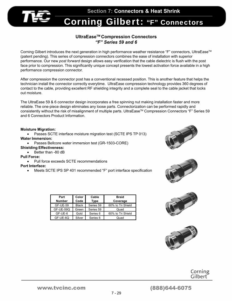
UltraEaseTM Compression Connectors
“F” Series 59 and 6
Corning Gilbert introduces the next generation in high performance weather resistance “F” connectors, UltraEaseTM
(patent pending). This series of compression connectors combines the ease of installation with superior
performance. Our new post forward design allows easy verification that the cable dielectric is flush with the post
face prior to compression. This significantly unique concept presents the lowest activation force available in a high
performance compression connector.
After compression the connector post has a conventional recessed position. This is another feature that helps the
technician install the connector correctly everytime. UltraEase compression technology provides 360 degrees of
contact to the cable, providing excellent RF shielding integrity and a complete seal to the cable jacket that locks
out moisture.
The UltraEase 59 & 6 connector design incorporates a free spinning nut making installation faster and more
reliable. The one-piece design eliminates any loose parts. Connectorization can be performed rapidly and
consistently without the risk of misalignment of multiple parts. UltraEaseTM Compression Connectors “F” Series 59
and 6 Connectors Product Information.
Broadband
Moisture Migration:
• Passes SCTE interface moisture migration test (SCTE IPS TP 013)
Water Immersion:
• Passes Bellcore water immersion test (GR-1503-CORE)
Shielding Effectiveness:
• Better than -80 dB
Pull Force:
• Pull force exceeds SCTE recommendations
Port Interface:
• Meets SCTE IPS SP 401 recommended “F” port interface specification
Part
Number
Color
Code
Cable
Type
Braid
Coverage
GF-UE-59 Black Series 59 60% to Tri Shield
GF-UE-59Q Green Series 59 Quad
GF-UE-6 Gold Series 6 60% to Tri Shield
GF-UE-6Q Silver Series 6 Quad

www.tvcinc.com
Section 7: Connectors & Heat Shrink
Corning Gilbert : “F” Connectors
(888)644-60757 - 30
Part
Number
Cable
Type
Crimp
Size
GF-360-59 Series 59 .360 Hex
GF-360-59Q Series 59 Quad .360 Hex
GF-360-6 Series 6 .360 Hex
GF-360-6Q Series 6 Quad .360 Hex
Series 56 and 6
Part
Number
Cable
Type
Crimp
Size
GF-59-AHS/USA 60% - Quad .360 hex
GF-6-AHS/USA 60% - Quad .360 hex
USA "F" Male
“F” Series Connectors
“F” connectors allow a coaxial cable to maintain a 75-ohm imped-
ance. They are used with 59, 6, 7 and 11 cable series. Use of “F”
connectors helps avoid impedance problems with interfaces and
splices.
• 59 and 6 “F” connectors are available in a convenient
feed-through design.
• 7 and 11 connectors have an internal pin contact that
mate to female ports.
• Our family of universal connectors is designed to accept
60% through Quad shield cables. They maintain good
electrical and mechanical properties and are installed with
a crimp tool.
360 “F” Connectors
USA “F” Connectors
Part
Number
Cable
Type
Crimp
Size
GAF-360-7 Series 7 .410 Hex
GAF-360-7Q Series 7 Quad .410 Hex
GAF-360-11 Series 11 .475 Hex
GAF-360-11Q Series 7 Quad .475 Hex
Series 7 and 11
AHS “F” Connectors
Part
Number
Crimp
Size
Braid
Coverage
GF-59-AHS/290 .324 HEX 40% - 60%
GF-59-AHS/312 .324 HEX 60% - 90%
GF-59-AHS/322 .324 HEX 60% - 90%
GF-59-AHS/342 .324 HEX Quad 60 / 40%
GF-59-AHS/357 .324 HEX Quad High Braid %
GF-59-AHP/284 .324 HEX Low Braid Plenum
GF-59-AHP/312 .324 HEX High Braid Plenum
GF-6-AHS/322 .324 HEX 40% - 60%
GF-6-AHS/342 .324 HEX Quad 60 / 40%
GF-6-AHS/357 .324 HEX Quad High Braid %
GF-6-AHP/312 .324 HEX Low Braid Plenum
GF-6-AHP/328 .324 HEX High Braid Plenum
"F" Male Connector
Part
Number
Crimp
Size
Braid
Coverage
GAF-236/051-AHS/368 0.384 Hex Single Braid
GAF-236/051-AHS/398 0.475 Hex Quad
GAF-11-AHS/460 .475 Hex Up to 90%
GAF-11-AHS/480 .475 Hex Quad
GAF-11-AHP/450 .475 Hex Plenum
Series 7 Integral Pin
Series 11 Integral Pin
Part
Number
Crimp
Size
Braid
Coverage
GF-11-AHS/460 .100 x .475 Hex Up to 90%
GF-11-AHS/480 .100 x .475 Hex Quad
GF-11-AHP/450 .100 x .475 Hex Plenum
Series 11 Crimp-on Pin

www.tvcinc.com
Section 7: Connectors & Heat Shrink
Corning Gilbert : “F” Accessories
(888)644-60757 - 31
Bonding Blocks and F-81 Drop Products
Corning Gilbert’s next generation of high frequency drop products are designed for the highest electrical perfor-
mance while maintaining excellent extended reliability.
The cylindrical contact design has four points of contact, not the two found in most
high performance products. Contacts are manufactured from BeCu to insure
reusability while maintaining high contact force. All F-female ports have a flat
reference plane for maximum surface contact. F-females are machined
from brass and nickel plating for maximum corrosion resistance.
Bonding blocks are manufactured from 6000 series aluminum and
accept #14 AWG to #6 AWG copper ground wire. All mounting and
bonding screws are accessible when installed. The sufficient leg length
allows connectors to be easily removed while the bonding block is
installed.
Product Features and Benefits
Bonding Blocks
• 6000 series aluminum for excellent corrosion properties and low electrical resistance
• Accepts #14 AWG to #6 AWG grounding conductor
• Available in both single and dual versions
• UL Listed
• Mounting screws and bonding wire screw are accessible when mounted & connectorized
• Tall legs allow for easy connector installation
• Mounting screws optional
F-81’s
• Wider center hex body to allow easy wrench access
• Also available with single or double D flats
Ordering Information
• GF-81-HFB (see figure 3)
• GGB-HFB-U (see figure 1)
• GGB-HFB-U-SCR (see figure 1)
• GGB-HFB-DU (see figure 2)
• GGB-HFB-DU-SCR (see figure 2)

www.tvcinc.com
Section 7: Connectors & Heat Shrink
Corning Gilbert : “F” Accessories
(888)644-60757 - 32
Female “F” Splice
Female Splice (Spring Contact)
• GF-81 (A) = .72 (B) = .26 (C) = 1.06 .020 - .047
• GF-81-A (A) = .48 (B) = .26 (C) = .81 .020 - .047
• GF-81-S (A) = .73 (B) = .26 (C) = 1.13 .020 - .047
Female Splice (Spring Contact)
• GF-81-TS . (A) = 510 (B) = .510 (C) 1.108 .020 - .047
• GF-81-HP1 (A) = .510 (B) = .510 (C) = 1.108 .020 - .0511 High Performance Spring Contact for Superior Return Loss
Female Splice (Spring Contact)
• GF-81-HP-6 (A) = .470 (B) = .255 (C) = .785 .030 - .040
• GF-81-HP-59 (A) = .470 (B) = .255 (C) = .785 .025 - .032High Performance Spring Contact for Superior Return Loss
Female Splice (Spring Contact)
• GF-81-A-SP .020 - .047
Female Chassis
• GF-61-A .020 - .047
Female Chassis
• GF-61-AS .020 - .047
Male Chassis
• GF-59-CH-A
“F” Male to “F” Male Splice
• GF-71-M

www.tvcinc.com
Section 7: Connectors & Heat Shrink
Corning Gilbert : “F” Accessories
(888)644-60757 - 33
“F” Push-On Adapter
• GPF-59 (A) = .500 (B) = .040 .020 - .047
• NS-2467-1 (A) = .500 (B) = .025 .023 - .030
Security Shield
• NS-2412-13 Steel (A) = 1.030 (B) = .585 (C) = .660For use with Terminator and Security Shield Tool above
Security Shield Tool
• G-S-200
90 “F” Adapter
• GF-MF/90 .020 - .047
“F” Series Accessories
When installed on a standard “F” female port, (ANSI/SCTE-IPS-
SP-400-1996), this product gives a weather resistant seal with
any UltraSeal or Gilbert 360 series connector.
BNC Female to “F” Male
• G-BNCF-FM 75 Ohms
Universal BNC Connector
• GA-BNC-59-AHS/USA-L .360 Hex 59 Series 40% - Quad
• GA-BNC-6-AHS/USA-L .360 Hex 6 Series 40% - Quad
BNC Male to “F” Female
• G-BNCF-MF 75 Ohms .020 - .047
Seal Ring
• G-SR-1/2Contact our TVC for correct applications and
for availability in other sizes

www.tvcinc.com
Section 7: Connectors & Heat Shrink
Corning Gilbert : “F” Accessories
(888)644-60757 - 34
“F” Series Terminators and Accessories
Our “F” series terminators are passive electronic circuitry designed to block 60 cycle and terminate RF signals on
unused equipment ports. They are necessary to prevent impedance mismatches and minimize RF reflections and
echoes. Unused active ports on trunk or feeder equipment should have a terminator installed. We offer a wide
variety of terminators and drop accessories for a range of applications.
75 Ω Ω Ω Ω Ω Terminator
• GTR-59-A
75 Ω Ω Ω Ω Ω Precision Terminator
• NS-3082-1
Security Shield Tool
• G-S-200
Security Shield
• NS-2412-13 Steel (A)1.030 (B).585 (C).660
For use with Terminator and Security Shield Tool
75 Ω Ω Ω Ω Ω Power Blocking Terminator
• GTR-59-DCB
Incorporates a capacitor to block 60 Hz AC Power
75 Ω Ω Ω Ω Ω Power Blocking Terminator
• GTR-59-S
Designed for use with Security Shields and Security Shield Tool

www.tvcinc.com
Section 7: Connectors & Heat Shrink
Corning Gilbert : “F” Accessories
(888)644-60757 - 35
Terminator Tool
• IT-59-TP-S (A) = 6.00
• IT-59-TP-L (B) = 8.00
Terminator Tool
• NS-6270-1 (A) = 1.74 (B) = .750
• NS-6270-3 (A) = 5.74 (B) = 4.75
Theft Proof
• GTR-59-TP Resistor, Gasket
• GTP-59-TP-SP No Resistor, GasketRequires IT-59-TP-S or IT-59-TP-L tools for installation and removal
Theft Proof Terminator
• NS-5762-3 Resistor, No Gasket
• NS-5762-9 No Resistor, No Gasket
• NS-5762-11 Resistor, Gasket
• NS-5762-13 No Resistor, GasketRequires NS-6270-1 or NS-6270-3 tools for installation and removal
Theft Proof
• NS-7291-5 No Resistor, No Gasket
• NS-7291-9 Resistor, No GasketRequires NS-7341-1 tool for installation and removal
Terminator Tool
• NS-7341-1
Theft Proof Terminator
• GTP-59 Resistor, Gasket
• GTP-59-LR No Resistor, Gasket
• NS-5762-5 Resistor, Gasket, Silicone Grease
• NS-5762-7 Resistor, Gasket, Ident. Groove
• NS-3268-5 No Resistor, Gasket, Silicone GreaseRequires G-GTT-4 or G-GTT-7 tools for installation and removal
Terminator Tool
• G-GTT-4 (A) = 2.27
• G-GTT-7 (B) = 3.93

www.tvcinc.com
Section 7: Connectors & Heat Shrink
Corning Gilbert : G2 Series 2-Piece
(888)644-60757 - 36
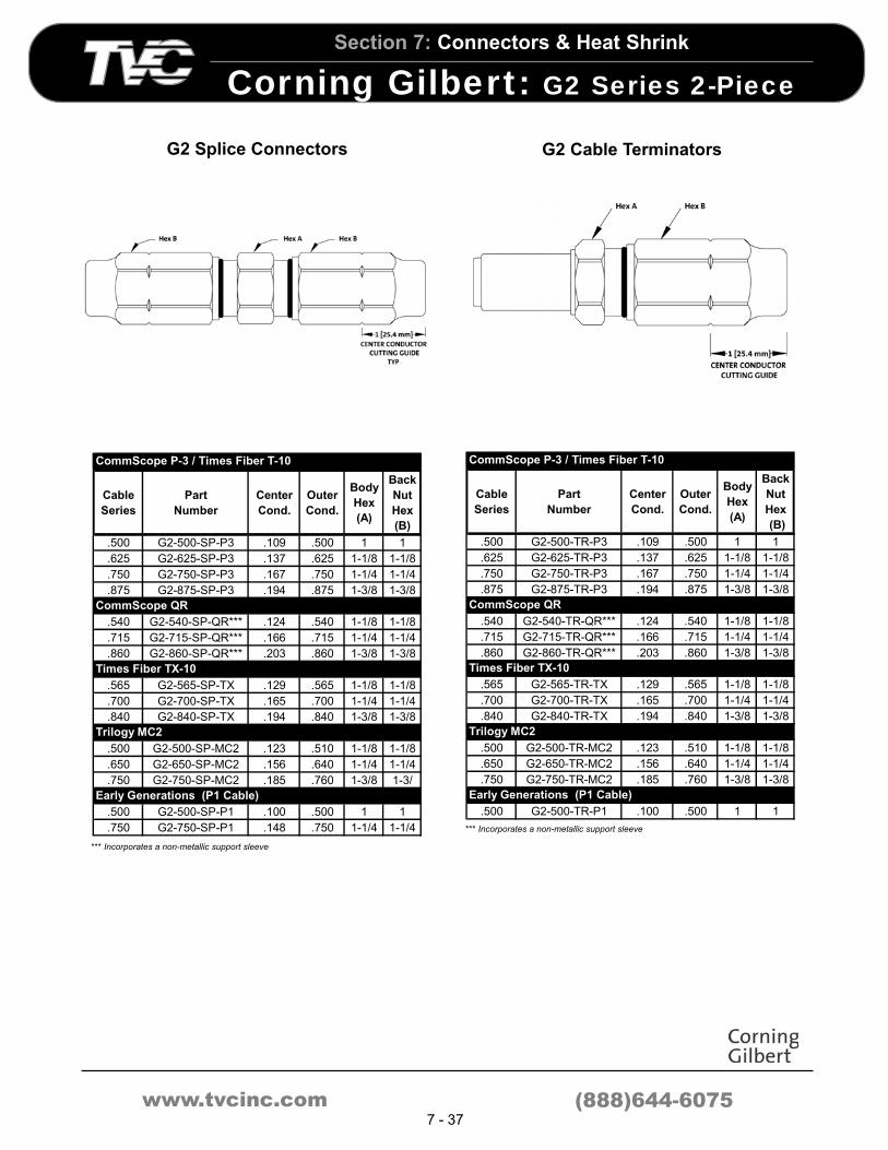
G2 Series 2-Piece Trunk and Distribution Connectors
G2 series 2-piece trunk and distribution connectors provide superior performance, while eliminating the common
disadvantages of traditional 2-piece designs.
• Provides installers a full view of the cable’s center conductor insertion into the connector seizing
mechanism (no blind entry)
• Incorporates a patented support sleeve located in the back nut of the connector, minimizing cable “pull
back”
• The Tri-Start thread system (patent pending) minimizes the required back nut rotations when tightening
the connector
• Domed insulator at the KS interface prevents moisture from collecting between the contact pin and
connector body, reducing the possibility of corrosion
• Non-rotational design for installation and disassembly
• The G2 connectors have a center conductor cutting guide
• Unique closing mechanism preserves reusability
*** Incorporates a non-metallic support sleeve
Cable
Series
Part
Number
Center
Cond.
Outer
Cond.
Body
Hex
(A)
Back
Nut
Hex
(B)
.500 G2-500-CH-P3 .109 .500 1 1
.625 G2-625-CH-P3 .137 .625 1-1/8 1-1/8
.750 G2-750-CH-P3 .167 .750 1-1/4 1-1/4
.875 G2-875-CH-P3 .194 .875 1-3/8 1-3/8
.540 G2-540-CH-QR*** .124 .540 1-1/8 1-1/8
.715 G2-715-CH-QR*** .166 .715 1-1/4 1-1/4
.860 G2-860-CH-QR*** .203 .860 1-3/8 1-3/8
.565 G2-565-CH-TX .129 .565 1-1/8 1-1/8
.700 G2-700-CH-TX .165 .700 1-1/4 1-1/4
.840 G2-840-CH-TX .194 .840 1-3/8 1-3/8
.500 G2-500-CH-MC2 .123 .510 1-1/8 1-1/8
.650 G2-650-CH-MC2 .156 .640 1-1/4 1-1/4
.750 G2-750-CH-MC2 .185 .760 1-3/8 1-3/8
.500 G2-500-CH-P1 .100 .500 1 1
.750 G2-750-CH-P1 .148 .750 1-1/4 1-1/4
Early Generations (P1 Cable)
CommScope P-3 / Times Fiber T-10
CommScope QR
Times Fiber TX-10
Trilogy MC2
*** Incorporates a non-metallic support sleeve
Cable
Series
Part
Number
Center
Cond.
Outer
Cond.
Body
Hex
(A)
Back
Nut
Hex
(B)
.500 G2-500-EXT-3-P3 .109 .500 1 1
.625 G2-625-EXT-3-P3 .137 .625 1-1/8 1-1/8
.750 G2-750-EXT-3-P3 .167 .750 1-1/4 1-1/4
.875 G2-875-EXT-3-P3 .194 .875 1-3/8 1-3/8
.540 G2-540-EXT-3-QR*** .124 .540 1-1/8 1-1/8
.715 G2-715-EXT-3-QR*** .166 .715 1-1/4 1-1/4
.860 G2-860-EXT-3-QR*** .203 .860 1-3/8 1-3/8
.565 G2-565-EXT-3-TX .129 .565 1-1/8 1-1/8
.700 G2-700-EXT-3-TX .165 .700 1-1/4 1-1/4
.840 G2-840-EXT-3-TX .194 .840 1-3/8 1-3/8
.500 G2-500-EXT-3-MC2 .123 .510 1-1/8 1-1/8
.650 G2-650-EXT-3-MC2 .156 .640 1-1/4 1-1/4
.750 G2-750-EXT-3-MC2 .185 .760 1-3/8 1-3/8
.500 G2-500-EXT-3-P1 .100 .500 1 1
.750 G2-750-EXT-3-P1 .148 .750 1-1/4 1-1/4
Early Generations (P1 Cable)
CommScope P-3 / Times Fiber T-10
CommScope QR
Times Fiber TX-10
Trilogy MC2
G2 Pin Connectors G2 Extension Connectors
www.tvcinc.com
Section 7: Connectors & Heat Shrink
Corning Gilbert : G2 Series 2-Piece
(888)644-60757 - 37
Cable
Series
Part
Number
Center
Cond.
Outer
Cond.
Body
Hex
(A)
Back
Nut
Hex
(B)
.500 G2-500-SP-P3 .109 .500 1 1
.625 G2-625-SP-P3 .137 .625 1-1/8 1-1/8
.750 G2-750-SP-P3 .167 .750 1-1/4 1-1/4
.875 G2-875-SP-P3 .194 .875 1-3/8 1-3/8
.540 G2-540-SP-QR*** .124 .540 1-1/8 1-1/8
.715 G2-715-SP-QR*** .166 .715 1-1/4 1-1/4
.860 G2-860-SP-QR*** .203 .860 1-3/8 1-3/8
.565 G2-565-SP-TX .129 .565 1-1/8 1-1/8
.700 G2-700-SP-TX .165 .700 1-1/4 1-1/4
.840 G2-840-SP-TX .194 .840 1-3/8 1-3/8
.500 G2-500-SP-MC2 .123 .510 1-1/8 1-1/8
.650 G2-650-SP-MC2 .156 .640 1-1/4 1-1/4
.750 G2-750-SP-MC2 .185 .760 1-3/8 1-3/
.500 G2-500-SP-P1 .100 .500 1 1
.750 G2-750-SP-P1 .148 .750 1-1/4 1-1/4
Early Generations (P1 Cable)
CommScope P-3 / Times Fiber T-10
CommScope QR
Times Fiber TX-10
Trilogy MC2
Cable
Series
Part
Number
Center
Cond.
Outer
Cond.
Body
Hex
(A)
Back
Nut
Hex
(B)
.500 G2-500-TR-P3 .109 .500 1 1
.625 G2-625-TR-P3 .137 .625 1-1/8 1-1/8
.750 G2-750-TR-P3 .167 .750 1-1/4 1-1/4
.875 G2-875-TR-P3 .194 .875 1-3/8 1-3/8
.540 G2-540-TR-QR*** .124 .540 1-1/8 1-1/8
.715 G2-715-TR-QR*** .166 .715 1-1/4 1-1/4
.860 G2-860-TR-QR*** .203 .860 1-3/8 1-3/8
.565 G2-565-TR-TX .129 .565 1-1/8 1-1/8
.700 G2-700-TR-TX .165 .700 1-1/4 1-1/4
.840 G2-840-TR-TX .194 .840 1-3/8 1-3/8
.500 G2-500-TR-MC2 .123 .510 1-1/8 1-1/8
.650 G2-650-TR-MC2 .156 .640 1-1/4 1-1/4
.750 G2-750-TR-MC2 .185 .760 1-3/8 1-3/8
.500 G2-500-TR-P1 .100 .500 1 1
Early Generations (P1 Cable)
CommScope P-3 / Times Fiber T-10
CommScope QR
Times Fiber TX-10
Trilogy MC2
G2 Splice Connectors G2 Cable Terminators
*** Incorporates a non-metallic support sleeve
*** Incorporates a non-metallic support sleeve

www.tvcinc.com
Section 7: Connectors & Heat Shrink
Corning Gilbert : G2 Series 2-Piece
(888)644-60757 - 38
*** Incorporates a non-metallic support sleeve
Cable
Series
Part
Number
Center
Cond.
Outer
Cond.
Body
Hex
(A)
Back
Nut
Hex
(B)
.500 G2-500-BAFF-P3 .109 .500 1 1
.625 G2-625-BAFF-P3 .137 .625 1-1/8 1-1/8
.750 G2-750-BAFF-P3 .167 .750 1-1/4 1-1/4
.875 G2-875-BAFF-P3 .194 .875 1-3/8 1-3/8
.540 G2-540-BAFF-QR*** .124 .540 1-1/8 1-1/8
.715 G2-715-BAFF-QR*** .166 .715 1-1/4 1-1/4
.860 G2-860-BAFF-QR*** .203 .860 1-3/8 1-3/8
.565 G2-565-BAFF-TX .129 .565 1-1/8 1-1/8
.700 G2-700-BAFF-TX .165 .700 1-1/4 1-1/4
.840 G2-840-BAFF-TX .194 .840 1-3/8 1-3/8
.500 G2-500-BAFF-MC2 .123 .510 1-1/8 1-1/8
.750 G2-750-BAFF-MC2 .185 .760 1-3/8 1-3/8
.500 G2-500-BAFF-P1 .100 .500 1 1
.750 G2-750-BAFF-P1 .148 .750 1-1/4 1-1/4
Early Generations (P1 Cable)
Times Fiber TX-10
CommScope P-3 / Times Fiber T-10
CommScope QR
Times Fiber TX-10
Cable
Series
Part
Number
Center
Cond.
Outer
Cond.
Body
Hex
(A)
Back
Nut
Hex
(B)
.500 G2-500-AFM-P3 .109 .500 1 1
.625 G2-625-AFM-P3 .137 .625 1-1/8 1-1/8
.750 G2-750-AFM-P3 .167 .750 1-1/4 1-1/4
.875 G2-875-AFM-P3 .194 .875 1-3/8 1-3/8
.540 G2-540-AFM-QR*** .124 .540 1-1/8 1-1/8
.715 G2-715-AFM-QR*** .166 .715 1-1/4 1-1/4
.860 G2-860-AFM-QR*** .203 .860 1-3/8 1-3/8
.565 G2-565-AFM-TX .129 .565 1-1/8 1-1/8
.700 G2-700-AFM-TX .165 .700 1-1/4 1-1/4
.840 G2-840-AFM-TX .194 .840 1-3/8 1-3/8
.500 G2-500-AFM-MC2 .123 .510 1-1/8 1-1/8
.650 G2-650-AFM-MC2 .156 .640 1-1/4 1-1/4
.750 G2-750-AFM-MC2 .185 .760 1-3/8 1-3/8
.500 G2-500-AFM-P1 .100 .500 1 1
.750 G2-750-AFM-P1 .148 .750 1-1/4 1-1/4
Early Generations (P1 Cable)
CommScope P-3 / Times Fiber T-10
CommScope QR
Times Fiber QR
Trilogy MC2
G2 BAFF Connectors G2 AFM Connectors
*** Incorporates a non-metallic support sleeve

www.tvcinc.com
Section 7: Connectors & Heat Shrink
Corning Gilbert : GRS Series 3-PieceC
(888)644-60757 - 39
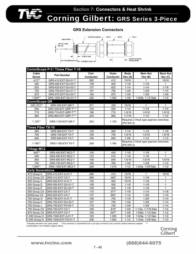
GRS Series 3-Piece Trunk and Distribution Connectors
GRS series 3-piece trunk and distribution connectors are used in low power RF, video, data signals and powered broadband systems.
Chassis mounting connectors are used in 5/8-24 equipment entry.
• Independent seizing of the center conductor permits installers to physically verify the center conductor has been seized prior to
tightening the back nut
• Placement of the integral mandrel of the connector in the main
nut provides a full view of the center conductor’s entrance into
the seizing mechanism and requires minimal pull back for ease
of installation
• Domed insulator at the KS interface prevents moisture from
collecting between the contact pin and connector body, reducing
the possibility of corrosion
• The GRS connectors have a center conductor cutting guide
• Reusable
Cable
SeriesPart Number
Cntr.
Cond.
Outer
Cond.Body Hex (A) Main Nut Hex (B) Back Nut Hex (C)
.412 GRS-412-CH-DU-01-T .092 .412 15/16 1 15/16
.500 GRS-500-CH-DU-03-T .109 .500 1-1/8 1-1/8 1
.625 GRS-625-CH-DU-02-T .137 .625 1-1/4 1-1/4 1-1/8
.750 GRS-750-CH-DU-01-T .167 .750 1-3/8 1-3/8 1-1/4
8.75 GRS-875-CH-DU-02-T .194 .875 1-3/8 1-3/8 1-3/8
1.000 GRS-1000-CH-DU-01-T .220 1.000 1-3/8 1-5/8ø, 1-1/2 flats 1-1/2
.320 (7C) GRS-320-CH-QR-T .071 .320 15/16 1 1
.540 GRS-540-CH-QRP-T*** .124 .540 1-1/4 1-1/4 1-1/4
.715 GRS-715-CH-QRP-T*** .166 .715 1-5/16 1-5/16 1-5/16
.860 GRS-860-CH-QRP-T*** .203 .860 1-7/16 1-1/2 1-1/2
1.125 GRS-1125-CH-QR-T .263 1.125
.480 GRS-480-CH-TX-T .109 .480 1-1/8 1-1/8 1
.565 GRS-565-CH-TX-T .129 .565 1-1/4 1-1/4 1-1/8
.700 GRS-700-CH-TX-T .165 .700 1-5/16 1-5/16 1-5/16
.840 GRS-840-CH-TX-T .194 .840 1-3/8 1-1/2 1-1/2
1.160 GRS-1160-CH-TX-T .269 1.160
.440 GRS-440-CH-MC2-T .105 .450 1-1/8 1-1/8 1
.500 GRS-500-CH-MC2-T .123 .510 1-1/8 1-1/8 1
.650 GRS-650-CH-MC2-T .156 .640 1-5/16 1-5/16 1-5/16
.750 GRS-750-CH-MC2-T .185 .760 1-3/8 1-3/8 1-1/4
1.000 GRS-1000-CH-MC2-T .248 1.015 1-1/2 1-3/4ø, 1-5/8 flats 1-1/2
.412 Grp. A GRS-412-CH-A-01-T .080 .412 13/16 1 15/16
.412 Grp. CX GRS-412-CH-CX-T .080 .482* 15/16 1-1/8 1
.500 Grp. C GRS-500-CH-A-01-T .100 .500 15/16 1-1/8 1
.500 Grp. D GRS-500-CH-DU-01-T .109 .500 1-1/8 1-1/8 1
.500 Grp. E GRS-500-CH-DU-02-T .109 .500 1-1/8 1-1/8 1
.500 Grp. F GRS-13.0-CH-DU-01-T .119 .509 1-1/8 1-1/8 1
.500 Grp. CX GRS-500-CH-CX-T .110 .571 1-1/8 1-1/4 1-1/8
.625 Grp. CX GRS-625-CH-CX-T .137 .693 1-1/4 1-3/8 1-1/4
.750 Grp. G GRS-750-CH-A-01-T .148 .750 1-1/8 1-3/8 1-1/4
.750 Grp. H GRS-750-CH-DU-03-T .167 .750 1-3/8 1-3/8 1-1/4
.750 Grp. J GRS-750-CH-FD-04-T .176 .750 1-3/8 1-3/8 1-1/4
.750 Grp. CX GRS-750-CH-CX-T .169 .816* 1-3/8 1-1/2ø, 1-7/16 flats 1-1/4
.875 Grp. CX GRS-875-CH-CX-T .194 .947* 1-3/8 1-5/8ø, 1-1/2 flats 1-1/2
1.000 Grp. O GRS-1000-CH-A-01-T .193 1.000 1-3/8 1-5/8ø, 1-1/2 flats 1-1/2
1.000 Grp. N GRS-1000-CH-FD-01-T .236 1.000 1-1/2 1-3/4ø, 1-5/8 flats 1-1/2
Requires 2 Hook type spanner wrenches (PN SW-2)
Trilogy MC2
Early Generations
CommScope P-3 / Times Fiber T-10
CommScope P-3 Quantum Reach (QR)
Requires 2 Hook type spanner wrenches (PN SW-2)
Times Fiber TX-10
www.tvcinc.com
Section 7: Connectors & Heat Shrink
Corning Gilbert : GRS Series 3-PieceC
(888)644-60757 - 40
GRS Extension Connectors
Cable
SeriesPart Number
Cntr.
Conductor
Outer
Conductor
Body
Hex (A)
Main Nut
Hex (B)
Back Nut
Hex (C)
.412** GRS-412-EXT-DU-01-T .092 .412 15/16 1 15/16
.500 GRS-500-EXT-DU-03-T .109 .500 1-1/8 1-1/8 1
.625 GRS-625-EXT-DU-02-T .137 .625 1-1/4 1-1/4 1-1/8
.750 GRS-750-EXT-DU-01-T .167 .750 1-3/8 1-3/8 1-1/4
.875 GRS-875-EXT-DU-02-T .194 .875 1-3/8 1-3/8 1-3/8
1.000** GRS-1000-EXT-DU-01-T .220 1.000 1-3/8 1-5/8ø, 1-1/2 flats 1-1/2
.320 (7C)** GRS-320-EXT-QR-T .071 .320 15/16 1 1
.540 GRS-540-EXT-QRP-T*** .124 .540 1-1/4 1-1/4 1-1/4
.715 GRS-715-EXT-QRP-T*** .166 .715 1-5/16 1-5/16 1-5/16
.860 GRS-860-EXT-QRP-T*** .203 .860 1-7/16 1-1/2 1-1/2
1.125** GRS-1125-EXT-QR-T .263 1.125
.565 GRS-565-EXT-TX-T .129 .565 1-1/4 1-1/4 1-1/8
.700 GRS-700-EXT-TX-T .165 .700 1-5/16 1-5/16 1-5/16
.840 GRS-840-EXT-TX-T .194 .840 1-3/8 1-1/2 1-1/2
1.160** GRS-1160-EXT-TX-T .269 1.160
.440** GRS-440-EXT-MC2-T .105 .450 1-1/8 1-1/8 1
.500 GRS-500-EXT-MC2-T .123 .510 1-1/8 1-1/8 1
.650 GRS-650-EXT-MC2-T .156 .640 1-5/16 1-5/16 1-5/16
.750 GRS-750-EXT-MC2-T .185 .760 1-3/8 1-3/8 1-1/4
1.000** GRS-1000-EXT-MC2-T .248 1.015 1-1/2 1-3/4ø, 1-5/8 flats 1-1/2
.412 Group A GRS-412-EXT-A-01-T .080 .412 13/16 1 15/16
.412 Group CX GRS-412-EXT-CX-T .080 .482* 15/16 1-1/8 1
.500 Group C GRS-500-EXT-A-01-T .100 .500 15/16 1-1/8 1
.500 Group D GRS-500-EXT-DU-01-T .109 .500 1-1/8 1-1/8 1
.500 Group E GRS-500-EXT-DU-02-T .109 .500 1-1/8 1-1/8 1
.500 Group CX GRS-500-EXT-CX-T .110 .571* 1-1/8 1-1/4 1-1/8
.625Group CX GRS-625-EXT-CX-T .137 .693* 1-1/4 1-3/8 1-1/4
.750 Group G GRS-750-EXT-A-01-T .148 .750 1-1/8 1-3/8 1-1/4
.750 Group H GRS-750-EXT-DU-03-T .167 .750 1-3/8 1-3/8 1-1/4
.750 Group J GRS-750-EXT-FD-04-T .176 .750 1-3/8 1-3/8 1-1/4
.750 Group CX GRS-750-EXT-CX-T .169 .816* 1-3/8 1-1/2ø, 1-7/16 flats 1-1/4
.875 Group CX GRS-875-EXT-CX-T .194 .947* 1-3/8 1-5/8ø, 1-1/2 flats 1-1/2
1.000 Group O GRS-1000-EXT-A-01-T .193 1.000 1-3/8 1-5/8ø, 1-1/2 flats 1-1/2
1.000 Group N GRS-1000-EXT-FD-01-T .236 1.000 1-1/2 1-3/4ø, 1-5/8 flats 1-1/2
Requires 2 Hook type spanner wrenches
(PN SW-2)
Trilogy MC2
Early Generations
CommScope P-3 / Times Fiber T-10
CommScope QR
Requires 2 Hook type spanner wrenches
(PN SW-2)
Times Fiber TX-10
*Indicates diameter over outer jacket ** Ext connector is assembled from a pin type connector and a socket contact extension adapter ***
Incorporates a non-metallic support sleeve

www.tvcinc.com
Section 7: Connectors & Heat Shrink
Corning Gilbert : GRS Series 3-PieceC
(888)644-60757 - 41
GRS Splice Connectors
Cable
SeriesPart Number
Cntr.
Conductor
Outer
Conductor
Body
Hex (A)
Main Nut
Hex (B)
Back Nut
Hex (C)
.412** GRS-412-EXT-DU-01-T .092 .412 15/16 1 15/16
.500 GRS-500-EXT-DU-03-T .109 .500 1-1/8 1-1/8 1
.625 GRS-625-EXT-DU-02-T .137 .625 1-1/4 1-1/4 1-1/8
.750 GRS-750-EXT-DU-01-T .167 .750 1-3/8 1-3/8 1-1/4
.875 GRS-875-EXT-DU-02-T .194 .875 1-3/8 1-3/8 1-3/8
1.000** GRS-1000-EXT-DU-01-T .220 1.000 1-3/8 1-5/8ø, 1-1/2 flats 1-1/2
.320 (7C)** GRS-320-EXT-QR-T .071 .320 15/16 1 1
.540 GRS-540-EXT-QRP-T*** .124 .540 1-1/4 1-1/4 1-1/4
.715 GRS-715-EXT-QRP-T*** .166 .715 1-5/16 1-5/16 1-5/16
.860 GRS-860-EXT-QRP-T*** .203 .860 1-7/16 1-1/2 1-1/2
1.125** GRS-1125-EXT-QR-T .263 1.125
.565 GRS-565-EXT-TX-T .129 .565 1-1/4 1-1/4 1-1/8
.700 GRS-700-EXT-TX-T .165 .700 1-5/16 1-5/16 1-5/16
.840 GRS-840-EXT-TX-T .194 .840 1-3/8 1-1/2 1-1/2
1.160** GRS-1160-EXT-TX-T .269 1.160
.440** GRS-440-EXT-MC2-T .105 .450 1-1/8 1-1/8 1
.500 GRS-500-EXT-MC2-T .123 .510 1-1/8 1-1/8 1
.650 GRS-650-EXT-MC2-T .156 .640 1-5/16 1-5/16 1-5/16
.750 GRS-750-EXT-MC2-T .185 .760 1-3/8 1-3/8 1-1/4
1.000** GRS-1000-EXT-MC2-T .248 1.015 1-1/2 1-3/4ø, 1-5/8 flats 1-1/2
.412 Group A GRS-412-EXT-A-01-T .080 .412 13/16 1 15/16
.412 Group CX GRS-412-EXT-CX-T .080 .482* 15/16 1-1/8 1
.500 Group C GRS-500-EXT-A-01-T .100 .500 15/16 1-1/8 1
.500 Group D GRS-500-EXT-DU-01-T .109 .500 1-1/8 1-1/8 1
.500 Group E GRS-500-EXT-DU-02-T .109 .500 1-1/8 1-1/8 1
.500 Group CX GRS-500-EXT-CX-T .110 .571* 1-1/8 1-1/4 1-1/8
.625Group CX GRS-625-EXT-CX-T .137 .693* 1-1/4 1-3/8 1-1/4
.750 Group G GRS-750-EXT-A-01-T .148 .750 1-1/8 1-3/8 1-1/4
.750 Group H GRS-750-EXT-DU-03-T .167 .750 1-3/8 1-3/8 1-1/4
.750 Group J GRS-750-EXT-FD-04-T .176 .750 1-3/8 1-3/8 1-1/4
.750 Group CX GRS-750-EXT-CX-T .169 .816* 1-3/8 1-1/2ø, 1-7/16 flats 1-1/4
.875 Group CX GRS-875-EXT-CX-T .194 .947* 1-3/8 1-5/8ø, 1-1/2 flats 1-1/2
1.000 Group O GRS-1000-EXT-A-01-T .193 1.000 1-3/8 1-5/8ø, 1-1/2 flats 1-1/2
1.000 Group N GRS-1000-EXT-FD-01-T .236 1.000 1-1/2 1-3/4ø, 1-5/8 flats 1-1/2
Requires 2 Hook type spanner wrenches
(PN SW-2)
Trilogy MC2
Early Generations
CommScope P-3 / Times Fiber T-10
CommScope QR
Requires 2 Hook type spanner wrenches
(PN SW-2)
Times Fiber TX-10
*Indicates diameter over outer jacket *** Incorporates a non-metalic support sleeve

www.tvcinc.com
Section 7: Connectors & Heat Shrink
Corning Gilbert : GRS Series 3-PieceC
(888)644-60757 - 42
GRS BAFF Connectors
*Indicates diameter over outer jacket *** Incorporates a non-metalic support sleeve
Cable
SeriesPart Number
Cntr.
Conductor
Outer
Conductor
Body
Hex (A)
Main Nut
Hex (B)
Back Nut
Hex (C)
.412 GRS-412-BAFF-DU-01 .092 .412 15/16 1 15/16
.500 GRS-500-BAFF-DU-03 .109 .500 1-1/8 1-1/8 1
.625 GRS-625-BAFF-DU-02 .137 .625 1-1/4 1-1/4 1-1/8
.750 GRS-750-BAFF-DU-01 .167 .750 1-3/8 1-3/8 1-1/4
.875 GRS-875-BAFF-DU-02 .194 .875 1-3/8 1-3/8 1-3/8
1.000 GRS-1000-BAFF-DU-01 .220 1.000 1-3/8 1-5/8ø, flats 1-1/2
.320 (7C) GRS-320-BAFF-QR .071 .320 15/16 1 1
.540 GRS-540-BAFF-QRP*** .124 .540 1-1/4 1-1/4 1-1/4
.715 GRS-715-BAFF-QRP*** .166 .715 1-5/16 1-5/16 1-5/16
.860 GRS-860-BAFF-QRP*** .203 .860 1-7/16 1-1/2 1-1/2
1.125 GRS-1125-BAFF-QR .263 1.125
.565 GRS-565-BAFF-TX .129 .565 1-1/4 1-1/4 1-1/8
.700 GRS-700-BAFF-TX .165 .700 1-5/16 1-5/16 1-5/16
.840 GRS-840-BAFF-TX .194 .840 1-3/8 1-1/2 1-1/2
1.160 GRS-1160-BAFF-TX .269 1.160
.440 GRS-440-BAFF-MC2 .105 .450 1-1/8 1-1/8 1
.500 GRS-500-BAFF-MC2 .123 .510 1-1/8 1-1/8 1
.650 GRS-650-BAFF-MC2 .156 .640 1-5/16 1-5/16 1-5/16
.750 GRS-750-BAFF-MC2 .185 .760 1-3/8 1-3/8 1-1/4
1.000 GRS-1000-BAFF-MC2 .248 1.015 1-1/2 1-3/4ø, 1-5/8 flats 1-1/2
.412 Group A GRS-412-BAFF-A-01 .080 .412 13/16 1 15/16
.412 Group CX GRS-412-BAFF-CX .080 .482* 15/16 1-1/8 1
.500 Group C GRS-500-BAFF-A-01 .100 .500 15/16 1-1/8 1
.500 Group D GRS-500-BAFF-DU-01 .109 .500 1-1/8 1-1/8 1
.500 Group E GRS-500-BAFF-DU-02 .109 .500 1-1/8 1-1/8 1
.500 Group CX GRS-500-BAFF-CX .110 .571* 1-1/8 1-1/4 1-1/8
.625 Group CX GRS-625-BAFF-CX .137 .693* 1-1/4 1-3/8 1-1/4
.750 Group G GRS-750-BAFF-A-01 .148 .750 1-1/8 1-3/8 1-1/4
.750 Group H GRS-750-BAFF-DU-03 .167 .750 1-3/8 1-3/8 1-1/4
.750 Group J GRS-750-BAFF-FD-04 .176 .750 1-3/8 1-3/8 1-1/4
.750 Group CX GRS-750-BAFF-CX .169 .816* 1-3/8 1-1/2ø, 1-7/16 flats 1-1/4
.875 Group CX GRS-875-BAFF-CX .194 .947* 1-3/8 1-5/8ø, 1-1/2 flats 1-1/2
1.000 Group O GRS-1000-BAFF-A-01 .193 1.000 1-3/8 1-5/8ø, 1-1/2 flats 1-1/2
1.000 Group N GRS-1000-BAFF-FD-01 .236 1.000 1-1/2 1-3/4ø, 1-5/8 flats 1-1/2
Requires 2 Hook type spanner wrenches
(PN SW-2)
Trilogy MC2
Early Generations
CommScope P-3 / Times Fiber T-10
CommScope QR
Requires 2 Hook type spanner wrenches
(PN SW-2)
Times Fiber TX-10

www.tvcinc.com
Section 7: Connectors & Heat Shrink
Corning Gilbert : GRS Series 3-PieceC
(888)644-60757 - 43
GRS Feed Through Connectors
Cable
SeriesPart Number
Cntr.
Conductor
Outer
Conductor
Body
Hex (A)
Back Nut
Hex (C)
.412 GRS-412-B-DU-01 .092 .412 1 1-15/16
.500 GRS-500-B-DU-03 .109 .500 1-1/8 1
.540 GRS-540-B-QR .124 .540 1-1/4 1-1/4
.440 GRS-440-B-MC2 .105 .450 1-1/8 1
.500 GRS-500-B-MC2 .123 .510 1-1/8 1
.500 Group D GRS-500-B-DU-01 .109 .500 1-1/8 1-1/8
CommScope P-3 / Times Fiber T-10
CommScope QR
Trilogy MC2
Early Generations

www.tvcinc.com
Section 7: Connectors & Heat Shrink
Corning Gilbert : Trunk & Dist .
(888)644-60757 - 44
Trunk and Distribution Adapters
Adapters are essential components to configure equipment for aerial and underground applications and are used to change
the direction of the cable where space is limited or where tight bends are required. Our adapters allow room to economize the
enclosures installed on municipal and customer properties. They eliminate the need for excess splicing in system rebuilds
and reduce the number of cables damaged through tight bending radiuses and other installation challenges. Seizure screws
or socket contacts are used to make contact with the mating connector pin.
Seizure Series Adapters
• Seizure screw versions use a screw to tighten down on either the cable’s center conductor in feed thru connectors
or the pin of the mating connector or adapter
Socket Series Adapters
• Socket contact adapters automatically make contact with the pin of the mating connector or adapter as the KS male
port is threaded into the adapter
• Both style of adapters are available with either jam nuts or swivel KS male ports to allow for proper orientation
• Reusable
• Center conductor trim guide
90º Seizure Screw Adaptors
Note: All 90 Degree Adapters on this page have 5/8-24 internal threads.
(Internal seizure accepts Center Conductors of .151 [3.8 mm] MAX.)
90º Seizure Swivel Ext.• GP-90-S-3.0-T (B)= 2.22
• GP-90-S-4.5-T (B)= 3.72
90º Seizure Swivel• GP-90-S-T (B)= 1.29
90º Seizure Screw• GP-90-T (B) = 1.00
90º Seizure Extension• GP-90-3.0-T (B)= 2.22
• GP-90-4.5-T (B)= 3.72

www.tvcinc.com
Section 7: Connectors & Heat Shrink
Corning Gilbert : Trunk & Dist .
(888)644-60757 - 45
90 Degree Socket Contact Adapters
Socket Contact Adapters
• Beryllium copper socket contact design
accepts pin diameter from .065 to .075 in.
[1.65 to 1.90 mm].
• Bright acid tin plated brass pin.
• AC power rating: 15 amps continuous.
• Return loss: >30 db to 1 GHz.
• KS male and KS female ports meet SCTE
interface practice standards.
• Body manufactured from ASTM 6262 alumi-
num alloy with chromate conversion coating.
90º Socket
• GL-90-SC-T (B) = 1.00
Accepts .065 [1.7mm] thru .075 [1.9mm] pin dia.
90º Socket Ext.
• GL-90-SC-w/1.5-T (B) = 2.46
• GL-90-SC-w/3-T (B) = 3.96
• GL-90-SC-w/4.5-T (B) = 5.46
• GL-90-SC-w/6-T (B) = 6.96
• GL-90-SC-w/9-T (B) = 9.96
Accepts .065 [1.7mm] thru .075 [1.9mm] pin dia.
90º Socket swivel
• GL-90-SC-S-T (B) = 1.29
Accepts .065 [1.7mm] thru .075 [1.9mm] pin dia.

www.tvcinc.com
Section 7: Connectors & Heat Shrink
Corning Gilbert : Trunk & Dist .
(888)644-60757 - 46
180o Degree Adapters
180o Seizure Screw
• GP-PA-T (B) = 5.18
• GP-PA-3.0-T (B) = 3.00
• GP-PA-4.5-T (B) = 4.50
180o Seizure Screw Swivel
• GP-PA-S-T (B) = 5.18
• GP-PA-S-3.0-T (B) = 3.00
• GP-PA-S-4.5-T (B) = 4.50
180o Socket Contact
• GL-180-SC-w/1.5-T (B) = 3.25
• GL-180-SC-w/3-T (B) = 4.75
• GL-180-SC-w/4.5-T (B) = 6.25
• GL-180-SC-w/6-T (B) = 7.75
• GL-180-SC-w/9-T (B) = 10.75

www.tvcinc.com
Section 7: Connectors & Heat Shrink
Corning Gilbert : Trunk & Dist .
(888)644-60757 - 47
Housing Terminators
These 75 ohm housing terminators block AC power and terminate RF signals in 75 Ohm characteristic impedance.
High Performance Terminator
G-SPTR-M-T
• Return loss 30 dB at 1 GHz
• Withstands 6 Kv surge perIEEE C62.41
combination wave
• Soldered construction forreliable performance
• Excellent CPD performance
• Impedance 75 ohm nominal
• KS male port meets SCTE interface practice
standards
• Body manufactured from 6000 series alumi-
num with a gold chromate conversion coating
• Tin alloy plated brass pin
• UV and ozone resistant EPDM o-ring
Performance Housing Terminator
GTR-KS-M-T
• Body: Brass Alloy C 36000
• Finish: Bright Acid Tin Plating
• Frequency: To 1 GHZ
• One piece body design to eliminate possible
ingress/egress of RF
• Impedance 75 ohm nominal
Housing Terminator
GTR-M-T
• Terminates both 60 cycle AC and RF signal
• Highly reliable
• Body manufactured from 6262 aluminum alloy
used for maximum corrosion resistance
• Impedance 75 ohm nominal

www.tvcinc.com
Section 7: Connectors & Heat Shrink
Corning Gilbert : Trunk & Dist .
(888)644-60757 - 48
Housing to Housing Adapters
Sealed Locking Rotational
G-KS-KS-MLKG-T
• 36 Rotational Locking Teeth
• Monel Mesh Gasket
• 5 O-rings seals
• Domed Insulators
Locking Rotational
G-KS-KS-MLK-T
• 36 Rotational Locking Teeth
• Short Overall Length
Rotational
G-KS-KS-M-T
• Short Overall Length
Non-Rotational
G-KS-KS-M-NR-T

www.tvcinc.com
Section 7: Connectors & Heat Shrink
Corning Gilbert : Trunk & Dist .
(888)644-60757 - 49
KS Male Adapters
KS Male to “F” Female
• GF-625-CH-S-T .020-.047 Pin accepted
KS Male to “F” Female
• GF-625-CH-T .020-.047 Pin accepted
KS Male to “F” Female
• GF-625-CH-DCB-T .020-.047 Pin accepted 60 Hz AC Power Block
KS Male to KS Female
• G-KSM/KSF-DCB-T .065-.075 Pin accepted60 Hz AC Power Block
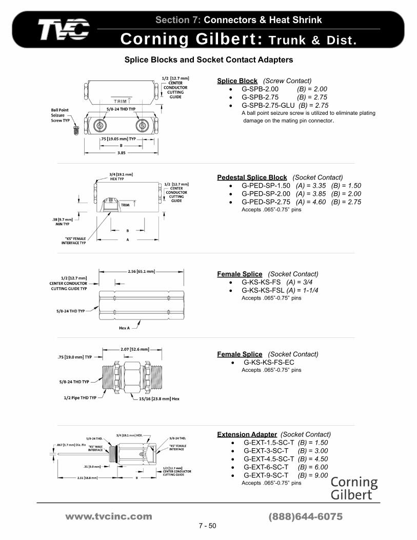
www.tvcinc.com
Section 7: Connectors & Heat Shrink
Corning Gilbert : Trunk & Dist .
(888)644-60757 - 50
Splice Blocks and Socket Contact Adapters
Splice Block (Screw Contact)
• G-SPB-2.00 (B) = 2.00
• G-SPB-2.75 (B) = 2.75
• G-SPB-2.75-GLU (B) = 2.75A ball point seizure screw is utilized to eliminate plating
damage on the mating pin connector.
Pedestal Splice Block (Socket Contact)
• G-PED-SP-1.50 (A) = 3.35 (B) = 1.50
• G-PED-SP-2.00 (A) = 3.85 (B) = 2.00
• G-PED-SP-2.75 (A) = 4.60 (B) = 2.75Accepts .065”-0.75” pins
Female Splice (Socket Contact)
• G-KS-KS-FS (A) = 3/4
• G-KS-KS-FSL (A) = 1-1/4Accepts .065”-0.75” pins
Female Splice (Socket Contact)
• G-KS-KS-FS-ECAccepts .065”-0.75” pins
Extension Adapter (Socket Contact)
• G-EXT-1.5-SC-T (B) = 1.50
• G-EXT-3-SC-T (B) = 3.00
• G-EXT-4.5-SC-T (B) = 4.50
• G-EXT-6-SC-T (B) = 6.00
• G-EXT-9-SC-T (B) = 9.00Accepts .065”-0.75” pins

www.tvcinc.com
Section 7: Connectors & Heat Shrink
Heat Shrink
(888)644-60757 - 51
CFTVDeveloped to meet the specific needs of the CATV Industry
Canusa CFTV Provides
• An absolutely waterproof seal and
mechanical protection
• Fast and simple installation. Clean and easy
connector re-entry
Unique CATV Sealant
• High performance Adhesive developed by
Canusa-EMI specifically for the CATV
industry
Selective Adhesion
• Selective stripability to meet CATV industry
needs
• Strong watertight bond to cable and cable
jacket. Yet, strips fast and clean for re-entry
to connector or splice
Non-Drip
• Will not drip at end of tube. Yet, flows
smoothly to fill all voids
Low Tack
• Will not bond to itself. For easier handling
and no waste
• Faster to install and easy to work with
Balanced System
• 3 synchronized components; stripes change
color, tubing shrinks and sealant flows
simultaneously
Fast Installation
• Minimum heat required to produce error free
installation without splitting
• No scorching; no risk of cable damage
in. mm. in. mm. in. mm. in. mm.
CFTV400 0.40 (10.2) 0.15 (3.8) .08 (2.0) 48 (1.22)
CFTV750 0.75 (19.0) 0.22 (5.6) .08 (2.0) 48 (1.22)
CFTV1100 1.10 (27.9) 0.40 (10.2) .08 (2.0) 48 (1.22)
CFTV1300 1.30 (33.0) 0.40 (10.2) .08 (2.0) 48 (1.22)
CFTV1500 1.50 (38.1) 0.50 (12.7) .08 (2.0) 48 (1.22)
CFTV1700 1.70 (43.2) 0.50 (12.7) .08 (2.0) 48 (1.22)
CFTV2050 2.05 (52.1) 0.75 (19.0) .08 (2.0) 48 (1.22)
CFTV2750 2.75 (69.8) 1.00 (25.4) .08 (2.0) 48 (1.22)
Wall Thickness Nom.
Std.
Lengths*
Recovered Dimensions
Internal Dia. Min. Internal Dia. Max.Part
Number
Expanded Dia. Min.
Ordering Information
Fast, Error-Free Installation
Balanced System
Selective Stripability

www.tvcinc.com
Section 7: Connectors & Heat Shrink
Heat Shrink
(888)644-60757 - 52
CTB-15 Self-Amalgamating Tape
CANUSA’s CTB-15 is an ethylene propylene rubber
based tape possessing excellent moisture and
corrosion protection. CTB-15 tape is self-
amalgamating, which when properly installed melds
together to create a tight fitting permanent boot of
protection. CTB-15 is an all purpose tape providing
superior UV and ozone protection plus low temperature
(-55°) flexibility.
• Self-amalgamating
• Outstanding UV and ozone resistant
• Clean stripable
• Easily applied - no tools required
• Excellent cold weather properties
• Insures tight waterproof seal
• No flame/heat required
Recommended Uses
• Provides protection where heat/flame is
prohibited
• Excellent re-entry protection without
interrupting service
• For housing to housing connectors
• For 90 degree connectors
Ordering Information
P/N Description Carton Qty.
CTB15 1.5" x 15' Roll 50
Dual Wall Heat Shrinkable Tubing
• Canusa “Drop” Tubing is a
flexible, thin wall, heat
shrinkable tubing with a
meltable inner liner.
• Environmentally Sealed
due to specially
formulated cross-linked
polyolefin tubing that
provides excellent U.V.
and ozone resistance. A
special internal adhesive
coating flows during shrinkage for complete
encapsulation and total corrosion protection!
• High Shrink Ratio with application of heat. Drop
Tubing shrinks to one-third it’s supplied diameter
(unless otherwise restricted) to accommodate all
FConnectors and cables.
• Easy Installation because Drop Tubing’s thin wall
and meltable adhesive liner are designed to shrink
with minimal heat ensuring fast, error-free
installation without damage to the cable.
Ordering Information
Internal
Dia
max.
Total Wall
Thickness
nom.
Adhesive
Thickness
nom.
DROP50 0.47 (12.0) 0.16 (4.0) 0.07 (1.75) .014 (0.35)
DROP75 0.75 (19.0) 0.24 (6.0) 0.09 (2.25) .016 (0.40)
RecoveredExp.
Internal
Dia
min .
P/N

www.tvcinc.com
Section 7: Connectors & Heat Shrink
Heat Shrink
(888)644-60757 - 53
GEL Drop Splice Enclosure
Gel filled closure is a simple, fast and effective method for providing complete environmental protection for Coaxial
Drop Splices in burial and aerial applications.
• Single Piece, Clam Shell Design, requires
no additional tools for installation
• GEL filled for complete waterproof protection
• Expansion Chambers prevent Gel overflow
• Accommodates a wide range of environmentally sealed Coaxial
connectors and cable types including quad shielded cable
• Available in two sizes: CE 596 for 59 and 6 series cable and CE 711
for 7 and 11 series cable
• Fully re-enterable
• Tough outer shell withstands impacts to 5 ft-lbs
• Meets SCTE IPS-TP-013 requirements for water immersion and
temperature cycling
Ordering Information
• CE 596
• CE 711
CFTV QuickSeal™
Heat Shrinkable wraparound sleeve with adhesive for complete environmental sealing without the need for
disconnection. Ideal for the protection of housing to housing connectors, retrofit protection of exposed connectors,
and the repair of damaged cable or fiber.
• Fast and simple installation without interruption of service
• Repair squirrel damaged cable
• Proven CANUSA CFTV adhesive ensures an absolutely
waterproof seal
• Selective strippability to meet CATV industry specifications
• Minimal heat required to produce error free installation without
splitting
• Thermochromatic lines that change color upon correct shrink
temperature
• CFTV QuickSeal™ can be cut to size in field to suit application
• Continuous operating temperature: -55°C to +110°C
Ordering Information
• Quickseal ................................36” strip
• Quickseal Kit ..........................9” strip
in cm in cm in mm in mm in mm
36 90 7 18 1.7 43 0.55 14 0.06 1.5
Recovered
Internal Dia
(max)
Recovered
Wall Thickness
(nom)
Length Width
Expanded
Internal Dia
(max)
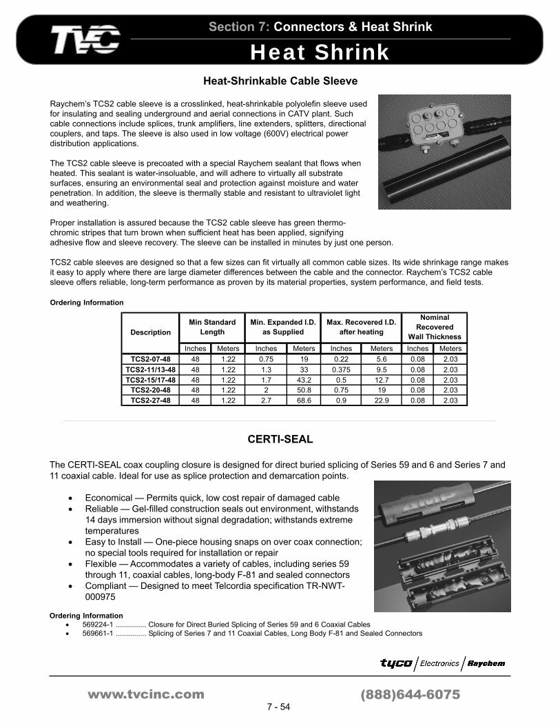
www.tvcinc.com
Section 7: Connectors & Heat Shrink
Heat Shrink
(888)644-60757 - 54
Heat-Shrinkable Cable Sleeve
Raychem’s TCS2 cable sleeve is a crosslinked, heat-shrinkable polyolefin sleeve used
for insulating and sealing underground and aerial connections in CATV plant. Such
cable connections include splices, trunk amplifiers, line extenders, splitters, directional
couplers, and taps. The sleeve is also used in low voltage (600V) electrical power
distribution applications.
The TCS2 cable sleeve is precoated with a special Raychem sealant that flows when
heated. This sealant is water-insoluable, and will adhere to virtually all substrate
surfaces, ensuring an environmental seal and protection against moisture and water
penetration. In addition, the sleeve is thermally stable and resistant to ultraviolet light
and weathering.
Proper installation is assured because the TCS2 cable sleeve has green thermo-
chromic stripes that turn brown when sufficient heat has been applied, signifying
adhesive flow and sleeve recovery. The sleeve can be installed in minutes by just one person.
TCS2 cable sleeves are designed so that a few sizes can fit virtually all common cable sizes. Its wide shrinkage range makes
it easy to apply where there are large diameter differences between the cable and the connector. Raychem’s TCS2 cable
sleeve offers reliable, long-term performance as proven by its material properties, system performance, and field tests.
Ordering Information
Inches Meters Inches Meters Inches Meters Inches Meters
TCS2-07-48 48 1.22 0.75 19 0.22 5.6 0.08 2.03
TCS2-11/13-48 48 1.22 1.3 33 0.375 9.5 0.08 2.03
TCS2-15/17-48 48 1.22 1.7 43.2 0.5 12.7 0.08 2.03
TCS2-20-48 48 1.22 2 50.8 0.75 19 0.08 2.03
TCS2-27-48 48 1.22 2.7 68.6 0.9 22.9 0.08 2.03
Description
Min Standard
Length
Min. Expanded I.D.
as Supplied
Max. Recovered I.D.
after heating
Nominal
Recovered
Wall Thickness
CERTI-SEAL
The CERTI-SEAL coax coupling closure is designed for direct buried splicing of Series 59 and 6 and Series 7 and
11 coaxial cable. Ideal for use as splice protection and demarcation points.
• Economical — Permits quick, low cost repair of damaged cable
• Reliable — Gel-filled construction seals out environment, withstands
14 days immersion without signal degradation; withstands extreme
temperatures
• Easy to Install — One-piece housing snaps on over coax connection;
no special tools required for installation or repair
• Flexible — Accommodates a variety of cables, including series 59
through 11, coaxial cables, long-body F-81 and sealed connectors
• Compliant — Designed to meet Telcordia specification TR-NWT-
000975
Ordering Information
• 569224-1 ............... Closure for Direct Buried Splicing of Series 59 and 6 Coaxial Cables
• 569661-1 ............... Splicing of Series 7 and 11 Coaxial Cables, Long Body F-81 and Sealed Connectors


