
Copyright 2014, Chrysler Group LLC, All Rights Reserved
Revised January 2014
Dealer Service Instructions for:
Safety Recall N49 / NHTSA 13V-529
Left Outer Tie Rod Assembly
NOTE: An inspection of the steering linkage type has been added to this recall.
The steering linkage inspection should be performed in the write-up area.
2008 (DH) Dodge RAM Truck (1500 series 4x4 Mega Cab)
2008 - 2009 (DH) Dodge RAM Truck (2500 / 3500 series 4x4)
2008 - 2009 (D1) Dodge RAM Truck (3500 series 4x4)
2010 - 2012 (D2) Dodge RAM Truck (3500 series 4x4)
2010 - 2012 (DJ) Dodge RAM Truck (2500 series 4x4)
2008 - 2010 (DC) Dodge RAM Truck (3500 Cab Chassis)
2011 - 2012 (DD) Dodge RAM Truck (3500 Cab Chassis)
NOTE: This recall applies only to the above vehicles built between February 14,
2008 and December 22, 2012 (MDH 021400 through 122218).
The left tie rod ball stud on about 264,000 of the above vehicles may fracture
under certain driving conditions. This could cause a loss of directional control
and/or a crash without warning.
Models
IMPORTANT: Some of the involved vehicles may be in dealer used vehicle
inventory. Dealers should complete this recall service on these vehicles before
retail delivery. Dealers should also perform this recall on vehicles in for service.
Involved vehicles can be determined by using the VIP inquiry process.
Subject
05/18/2015 SPECIAL ORDER - ENCLOSURE 1 - FCA US LLC - 000231

Safety Recall N49 – Left Outer Tie Rod Assembly Page 2
The steering linkage assembly must be inspected and replaced if required.
NOTE: The initial steering linkage inspection process can be done by write-up
personnel in the write-up area (see Section A. of the service procedure).
Vehicles found with original style steering linkage can be immediately
returned to the customer.
Part Number Description
CBUEN491AA Steering Linkage Package
Each package contains the following components:
Quantity Description
1 Tie Rod, Left
1 Tie Rod, Right
1 Sleeve, Adjuster
2 Clamp, Adjuster Sleeve
2 Bolt, Adjuster Sleeve
2 Nut, Adjuster Sleeve
Part Number Description
CBUEN492AA Steering Linkage Installation Package
Each package contains the following components:
Quantity Description
3 Nut, Hex Lock
1 Nut, Hex Flange
Each dealer to whom vehicles in the recall were assigned will receive enough
steering linkages to service about 10% of those vehicles.
The following special tool is required to perform this repair:
C4150 Puller, Tie Rod
Repair
Parts Information
Special Tools
05/18/2015 SPECIAL ORDER - ENCLOSURE 1 - FCA US LLC - 000232
Safety Recall N49 – Left Outer Tie Rod Assembly Page 3
NOTE: The initial steering linkage inspection process (Section A. of the service
procedure) can be done by write-up personnel in the write-up area. Vehicles
found with the steering linkage shown in Figure 1 can be immediately returned
to the customer. See the “Completion Reporting and Reimbursement” section of
this recall for special claims processing information.
A. Inspect Steering Linkage Type
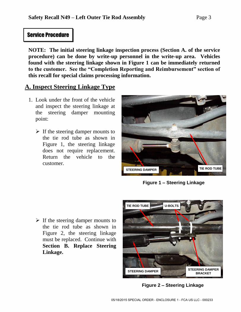
1. Look under the front of the vehicle
and inspect the steering linkage at
the steering damper mounting
point:
If the steering damper mounts to
the tie rod tube as shown in
Figure 1, the steering linkage
does not require replacement.
Return the vehicle to the
customer.
If the steering damper mounts to
the tie rod tube as shown in
Figure 2, the steering linkage
must be replaced. Continue with
Section B. Replace Steering
Linkage.
Service Procedure
Figure 1 – Steering Linkage
U-BOLTS TIE ROD TUBE
Figure 2 – Steering Linkage
STEERING DAMPER
BRACKET STEERING DAMPER
STEERING DAMPER TIE ROD TUBE
05/18/2015 SPECIAL ORDER - ENCLOSURE 1 - FCA US LLC - 000233

Safety Recall N49 – Left Outer Tie Rod Assembly Page 4
B. Replace Steering Linkage
1. Lift the vehicle on an appropriate
hoist.
2. Remove and save the front wheels.
3. Remove and discard the steering
damper nut (Figure 3)
4. Disconnect the steering damper from the steering linkage.
5. Remove and discard the drag link
nut at the right tie rod (Figure 4).
6. Using special tool C4150, separate
the drag link from the right tie rod.
Service Procedure
Figure 3 – Steering Damper Nut
Figure 4 – Drag Link Nut
STEERING DAMPER
DRAG LINK
NUT
DRAG LINK
RIGHT TIE
ROD
05/18/2015 SPECIAL ORDER - ENCLOSURE 1 - FCA US LLC - 000234
Safety Recall N49 – Left Outer Tie Rod Assembly Page 5
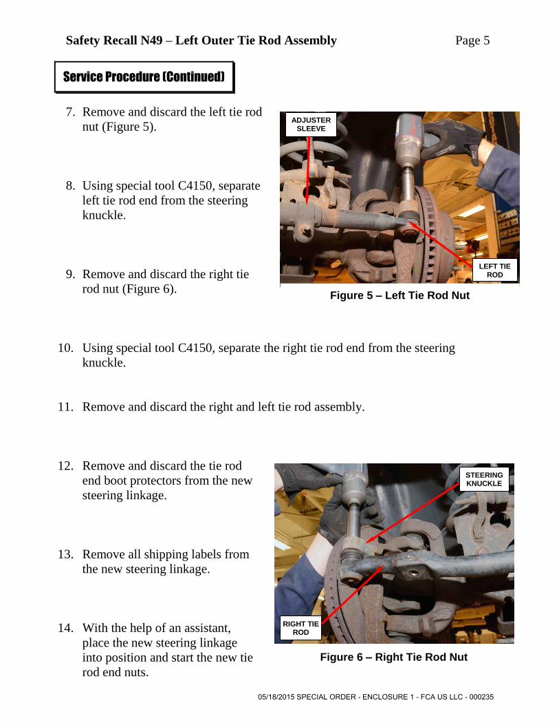
7. Remove and discard the left tie rod
nut (Figure 5).
8. Using special tool C4150, separate
left tie rod end from the steering
knuckle.
9. Remove and discard the right tie
rod nut (Figure 6).
10. Using special tool C4150, separate the right tie rod end from the steering
knuckle.
11. Remove and discard the right and left tie rod assembly.
12. Remove and discard the tie rod
end boot protectors from the new
steering linkage.
13. Remove all shipping labels from
the new steering linkage.
14. With the help of an assistant,
place the new steering linkage
into position and start the new tie
rod end nuts.
Service Procedure (Continued)
Figure 5 – Left Tie Rod Nut
Figure 6 – Right Tie Rod Nut
LEFT TIE ROD
ADJUSTER SLEEVE
RIGHT TIE ROD
STEERING KNUCKLE
05/18/2015 SPECIAL ORDER - ENCLOSURE 1 - FCA US LLC - 000235
Safety Recall N49 – Left Outer Tie Rod Assembly Page 6
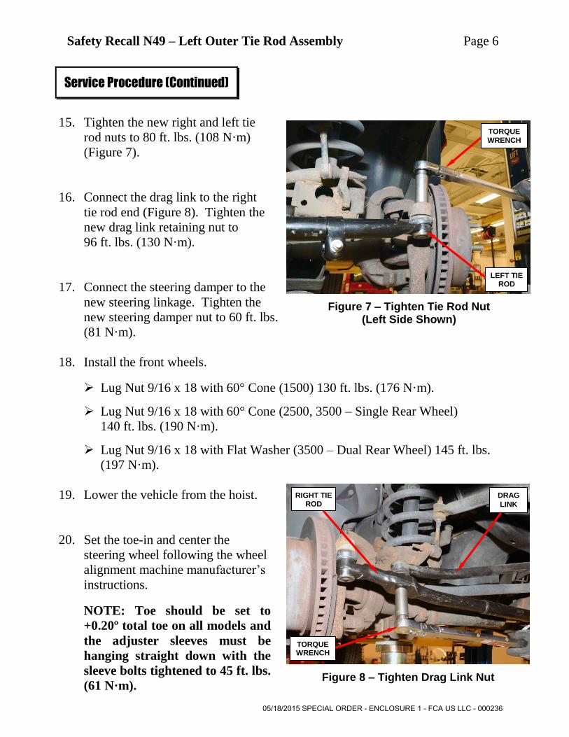
15. Tighten the new right and left tie
rod nuts to 80 ft. lbs. (108 N·m)
(Figure 7).
16. Connect the drag link to the right
tie rod end (Figure 8). Tighten the
new drag link retaining nut to
96 ft. lbs. (130 N·m).
17. Connect the steering damper to the
new steering linkage. Tighten the
new steering damper nut to 60 ft. lbs.
(81 N·m).
18. Install the front wheels.
Lug Nut 9/16 x 18 with 60° Cone (1500) 130 ft. lbs. (176 N·m).
Lug Nut 9/16 x 18 with 60° Cone (2500, 3500 – Single Rear Wheel)
140 ft. lbs. (190 N·m).
Lug Nut 9/16 x 18 with Flat Washer (3500 – Dual Rear Wheel) 145 ft. lbs.
(197 N·m).
19. Lower the vehicle from the hoist.
20. Set the toe-in and center the
steering wheel following the wheel
alignment machine manufacturer’s
instructions.
NOTE: Toe should be set to
+0.20º total toe on all models and
the adjuster sleeves must be
hanging straight down with the
sleeve bolts tightened to 45 ft. lbs.
(61 N·m).
Service Procedure (Continued)
Figure 7 – Tighten Tie Rod Nut (Left Side Shown)
Figure 8 – Tighten Drag Link Nut
TORQUE
WRENCH
LEFT TIE ROD
DRAG
LINK
TORQUE WRENCH
RIGHT TIE ROD
05/18/2015 SPECIAL ORDER - ENCLOSURE 1 - FCA US LLC - 000236

Safety Recall N49 – Left Outer Tie Rod Assembly Page 7
Claims for vehicles that have been serviced must be submitted on the
DealerCONNECT Claim Entry Screen located on the Service tab. Claims
submitted will be used by Chrysler to record recall service completions and
provide dealer payments.
Use the following labor operation number and time allowance:
Labor Operation Time
Number Allowance
Inspect steering linkage in write-up area 19-N4-91-81 0.0 hours
Replace steering linkage, set toe and
center steering wheel 19-N4-91-82 1.1 hours
Add the cost of the recall parts package plus applicable dealer allowance to your
claim.
FOR VEHICLES INSPECTED IN THE WRITE UP AREA: Enter
“INSPECT” in the part number section of your claim with a quantity of one
(1). Enter $5.00 WITH NO MARK-UP for reimbursement of steering linkage
inspection performed in the write up area.
NOTE: See the Warranty Administration Manual, Recall Claim Processing
Section, for complete recall claim processing instructions.
To view this notification on DealerCONNECT, select “Global Recall System” on
the Service tab, then click on the description of this notification.
Completion Reporting and Reimbursement
Dealer Notification
05/18/2015 SPECIAL ORDER - ENCLOSURE 1 - FCA US LLC - 000237

Safety Recall N49 – Left Outer Tie Rod Assembly Page 8
All involved vehicle owners known to Chrysler are being notified of the service
requirement by first class mail. They are requested to schedule appointments for
this service with their dealers. A generic copy of the owner letter is attached.
Enclosed with each owner letter is an Owner Notification postcard to allow owners
to update our records if applicable.
All involved vehicles have been entered into the DealerCONNECT Global Recall
System (GRS) and Vehicle Information Plus (VIP) for dealer inquiry as needed.
GRS provides involved dealers with an updated VIN list of their incomplete
vehicles. The owner’s name, address and phone number are listed if known.
Completed vehicles are removed from GRS within several days of repair claim
submission.
To use this system, click on the “Service” tab and then click on “Global Recall
System.” Your dealer’s VIN list for each recall displayed can be sorted by: those
vehicles that were unsold at recall launch, those with a phone number, city, zip
code, or VIN sequence.
Dealers must perform this repair on all unsold vehicles before retail delivery.
Dealers should also use the VIN list to follow up with all owners to schedule
appointments for this repair.
Recall VIN lists may contain confidential, restricted owner name and address information that
was obtained from the Department of Motor Vehicles of various states. Use of this information
is permitted for this recall only and is strictly prohibited from all other use.
If you have any questions or need assistance in completing this action, please
contact your Service and Parts District Manager.
Customer Services / Field Operations
Chrysler Group LLC
Owner Notification and Service Scheduling
Vehicle Lists, Global Recall System, VIP and Dealer Follow Up
Additional Information
05/18/2015 SPECIAL ORDER - ENCLOSURE 1 - FCA US LLC - 000238


