Transmitter
© 2006 Pyromation, Inc.
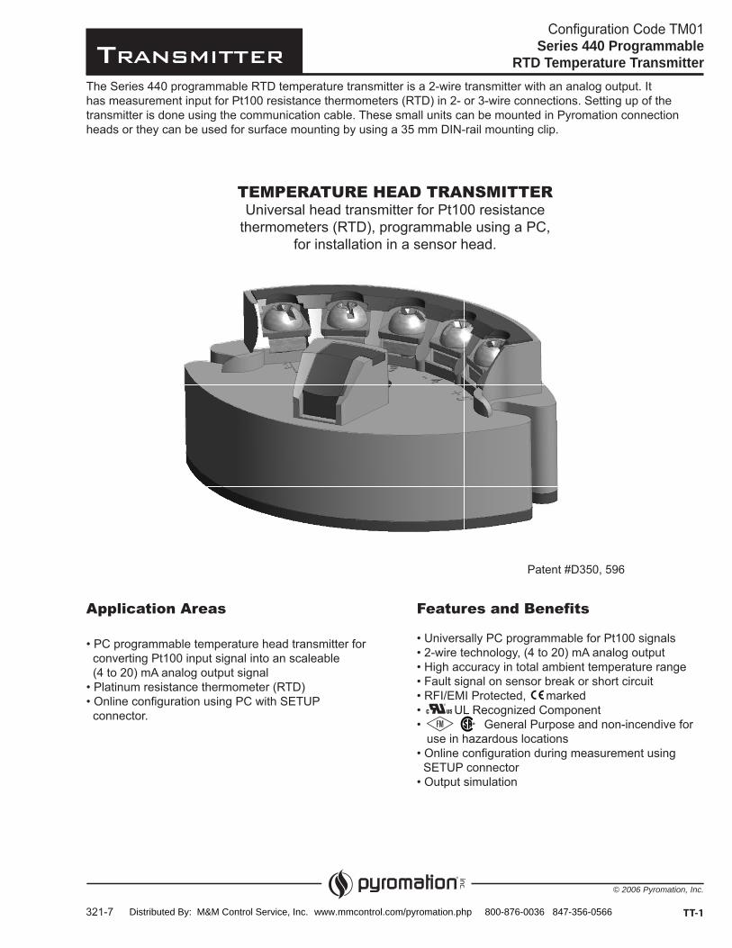
Features and Benefits
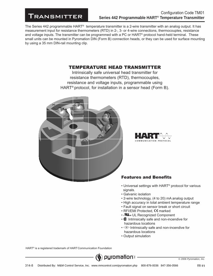
TEMPERATURE HEAD TRANSMITTER
Series 440 Programmable RTD Temperature Transmitter
TT-1
Application Areas
Distributed By: M&M Control Service, Inc. www.mmcontrol.com/pyromation.php 800-876-0036 847-356-0566

Transmitter
© 2006 Pyromation, Inc.
Configuration Code TM01Series 440 Programmable
RTD Temperature Transmitter
- -
322-6TT-2
ORDER CODES
1
CODE DESCRIPTION
2 RTD (2-wire)
3 RTD (3-wire)
3
CODE DESCRIPTION
U
D2
CODE DESCRIPTION
85 -1)
1
Example Configured Order Number: 3 85 U
2 3
S (50-300) F4 5Unconfigured Order Number:
4 4 0440-00[1]
4
RANGE
5
CODE DESCRIPTION
C Celsius
F Fahrenheit
Accessories
CODE DESCRIPTION
10303 Software (USB)
10307
3-wire Pt100 (0 -100)
Distributed By: M&M Control Service, Inc. www.mmcontrol.com/pyromation.php 800-876-0036 847-356-0566

Transmitter
© 2006 Pyromation, Inc.
Series 440 Programmable RTD TemperatureTransmitter Specifications
[1] % is related to the adjusted measurement range (the value to be applied is the greater)[2] All data is related to a measurement end value of 20 mA[3] Under reference conditions
323-7 TT-3
Resistance Thermometer Input (RTD)
TYPE MEASUREMENT RANGE MINIMUM RANGEoC-1)
Connection Type
Sensor cable resistance
Sensor current
Output (Analog)
Output signal (4 to 20) mA or (20 to 4) mA
Transmission as Temperature linear
Maximum load (Vpower supply
Induced current required
Current limit
Switch on delay 4 s (during power 1a
Electronic response time 1 s
Failure Mode
Undershooting measurement range
Exceeding measurement range
Sensor breakage/short circuit
Electronic Connection
Power supply Ub
Allowable ripple Uss b max
Resistance Thermometer Accuracy (RTD)
TYPE MEASUREMENT ACCURACY
Pt100 [1]
Reference conditions [73 ± 9]
General Accuracy
Influence of power supply [2]
Load influence [2]
Temperature drift Td
Long term stability [3] [1][3]
Distributed By: M&M Control Service, Inc. www.mmcontrol.com/pyromation.php 800-876-0036 847-356-0566

Transmitter
© 2006 Pyromation, Inc.
Series 440 Programmable RTD TemperatureTransmitter Specifications
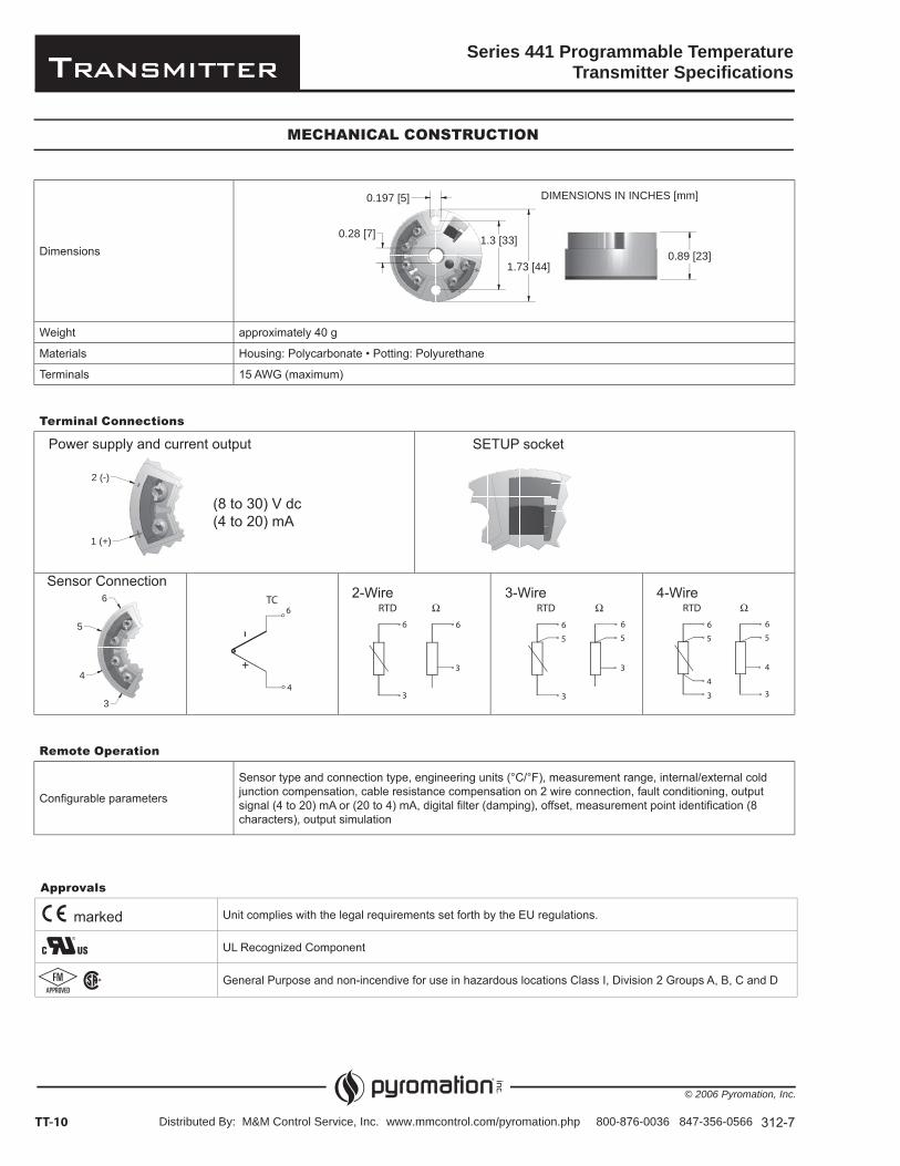
Terminal ConnectionsPower supply and current output
Mechanical Construction
Dimensions
Weight Approximately 44 g
Materials
Terminals 15 AWG (maximum)
324-6TT-4
(10 to 30) V dc(4 to 20) mA
2-Wire 3-Wire
Ambient Conditions
Ambient temperature (-40 to 85) oC [-40 to 185] oF
Storage temperature (-40 to 100) oC [-40 to 212] oF
Climatic class EN 60 654-1, Class C
Condensation Permitted
Shock resistance 4 g / (2 to 150) Hz according to IEC 60 068-2-6
EMC immunity Interference immunity and interference emission according to EN 61 326-1 (1EC 1326)
SETUP SOCKET
Approvals
Unit complies with the legal requirements set forth by the EU regulations.
UL Recognized Component
General Purpose and non-incendive for use in hazardous locations Class I, Division 2 Groups A, B, C and D
marked
1.49 [38]
0.24 [6]
1.75 [44]2.17 [55]
0.89 [23]
DIMENSIONS IN INCHES [mm]
Distributed By: M&M Control Service, Inc. www.mmcontrol.com/pyromation.php 800-876-0036 847-356-0566

Transmitter
© 2006 Pyromation, Inc.
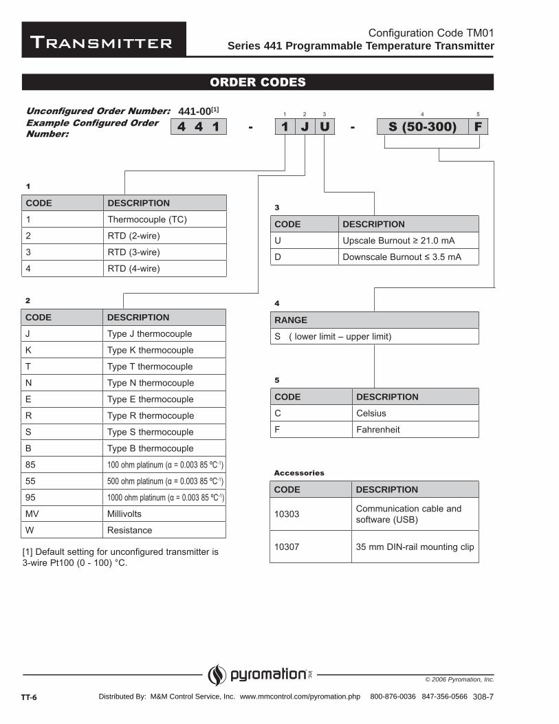
The Series 441 programmable temperature transmitter is a 2-wire transmitter with an analog output. It has measurement input for resistance thermometers (RTD) in 2-, 3- or 4-wire connections, thermocouples, resistance and voltage inputs. Setting up of the transmitter is done using the communication cable. These small units can be mounted in Pyromation DIN (Form B) connection heads or they can be used for surface mounting by using a 35 mm DIN-rail mounting clip.
TEMPERATURE HEAD TRANSMITTERUniversal head transmitter for resistance
thermometers (RTD), thermocouples, resistanceand voltage inputs, programmable using a PC,
for installation in a sensor head (Form B)
Configuration Code TM01Series 441 Programmable Temperature Transmitter
307-8 TT-5
Features and Benefits
Intrinsically safe and non-incendive for
for
Application Areas
converting various input signals into an scalable
Resistance thermometer (RTD) Thermocouple (TC)
Voltage (mV)
connector
Distributed By: M&M Control Service, Inc. www.mmcontrol.com/pyromation.php 800-876-0036 847-356-0566
Transmitter
© 2006 Pyromation, Inc.
Configuration Code TM01Series 441 Programmable Temperature Transmitter
- -
308-7TT-6
ORDER CODES
1
CODE DESCRIPTION
1 Thermocouple (TC)
2 RTD (2-wire)
3 RTD (3-wire)
4 RTD (4-wire)
3
CODE DESCRIPTION
U
D
2
CODE DESCRIPTION
J Type J thermocouple
K Type K thermocouple
T Type T thermocouple
N Type N thermocouple
E Type E thermocouple
R Type R thermocouple
S Type S thermocouple
B Type B thermocouple-1)-1)-1)
MV Millivolts
W Resistance
1
Example Configured Order Number: 1 J U
2 3
S (50-300) F4Unconfigured Order Number:
4 4 1441-00[1]
4
RANGE
S ( lower limit – upper limit)
5
CODE DESCRIPTION
C Celsius
F Fahrenheit
Accessories
CODE DESCRIPTION
10303 Communication cable and software (USB)
10307[1] Default setting for unconfigured transmitter is
Distributed By: M&M Control Service, Inc. www.mmcontrol.com/pyromation.php 800-876-0036 847-356-0566
Transmitter
© 2006 Pyromation, Inc.
Series 441 Programmable TemperatureTransmitter Specifications
TT-7309-5
INPUT
Resistance Thermometer (RTD)
TYPE MEASUREMENT RANGE MINIMUM RANGE
oC-1)Pt500Pt1000
oC-1)Ni500Ni1000
Connection type
t
Resistance ( )
TYPE MEASUREMENT RANGE MINIMUM RANGE
Thermocouples (TC)
TYPE MEASUREMENT RANGE MINIMUM RANGE
K (NiCr-Ni)
N (NiCrSi-NiSi)
500 500 500 50 50 50 50 50 500 500 50 50 500
Voltage (mV)
TYPE MEASUREMENT RANGE MINIMUM RANGE
Distributed By: M&M Control Service, Inc. www.mmcontrol.com/pyromation.php 800-876-0036 847-356-0566
Transmitter
© 2006 Pyromation, Inc.
Series 441 Programmable TemperatureTransmitter Specifications
310-7TT-8
[1] Not for thermocouple[2] % is related to the adjusted measurement range (the value to be applied is the greater)
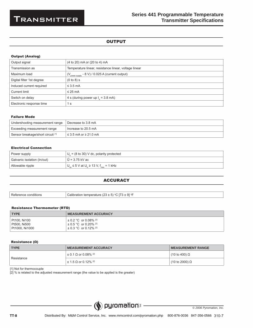
Output (Analog)
Output signal (4 to 20) mA or (20 to 4) mA
Transmission as Temperature linear, resistance linear, voltage linear
Maximum load (Vpower supply - 8 V) / 0.025 A (current output)
Digital filter 1st degree (0 to 8) s
Induced current required
Current limit
Switch on delay 4 s (during power up Ia = 3.8 mA)
Electronic response time 1 s
OUTPUT
Failure Mode
Undershooting measurement range Decrease to 3.8 mA
Exceeding measurement range Increase to 20.5 mA
Sensor breakage/short circuit [1]
Electrical Connection
Power supply Ub = (8 to 30) V dc, polarity protected
Galvanic isolation (In/out) Û = 3.75 kV ac
Allowable ripple Uss b max = 1 kHz
Reference conditions Calibration temperature (23 ± 5) oC [73 ± 9] oF
ACCURACY
Resistance Thermometer (RTD)
TYPE MEASUREMENT ACCURACY
Pt100, Ni100Pt500, Ni500Pt1000, Ni1000
± 0.2 °C or 0.08% [2]
± 0.5 °C or 0.20% [2]
± 0.3 °C or 0.12% [2]
Resistance ( )
TYPE MEASUREMENT ACCURACY MEASUREMENT RANGE
Resistance[2]
[2]
Distributed By: M&M Control Service, Inc. www.mmcontrol.com/pyromation.php 800-876-0036 847-356-0566
Transmitter
© 2006 Pyromation, Inc.
Series 441 Programmable TemperatureTransmitter Specifications
TT-9311-8
ACCURACY (continued)
Thermocouple (TC)
TYPE MEASUREMENT ACCURACY
K, J, T, E, L, UN, C, DS, B, R MoRe5-MoRe41
± 0.5 °C or 0.08% [1]
± 1.0 °C or 0.08% [1]
± 2.0 °C or 0.08% [1]
Influence of the internal reference junction
Pt100 ± (0.30 + 0.005 |t|) °C|t| = value of temperature without regard to sign °C
Voltage (mV)
TYPE MEASUREMENT ACCURACY MEASUREMENT RANGE
Millivolt (mV) ± 20 μV or 0.08% [1] (-10 to 100) mV
General Accuracy
Influence of power supply ± 0.01%/V deviation from 24 V [2]
Load influence [2]
Temperature drift
Resistive thermometer (RTD):Td Resistive thermometer Pt100:Td
Thermocouple (TC):Td
= Deviation of the ambient temperature according to the reference condition
Long term stability [3] [1][3]
[1] % is related to the adjusted measurement range (the value to be applied is the greater)[2] All data is related to a measurement end value of 20 mA[3] Under reference conditions
INSTALLATION CONDITIONS
Ambient Conditons
Ambient temperature (-40 to 85) °C [-40 to 185] °F
Storage temperature (-40 to 100) °C [-40 to 212] °F
Climatic class To EN 60 654-1, Class C
Moisture condensation Allowable
Vibration protection 4 g / (2 to 150) Hz according to IEC 60 068-2-6
EMC immunity Interference immunity and interference emission as per EN 61 326-1 (IEC 1326)
Distributed By: M&M Control Service, Inc. www.mmcontrol.com/pyromation.php 800-876-0036 847-356-0566
Transmitter
© 2006 Pyromation, Inc.
0.28 [7] 1.3 [33]
1.73 [44]0.89 [23]
0.197 [5] DIMENSIONS IN INCHES [mm]
Terminal Connections
Series 441 Programmable TemperatureTransmitter Specifications
Dimensions
Weight approximately 40 g
Materials
Terminals 15 AWG (maximum)
312-7TT-10
2 (-)
1 (+)
Power supply and current output
Sensor Connection2-Wire 3-Wire 4-Wire
SETUP socket
MECHANICAL CONSTRUCTION
Remote Operation
Configurable parameters
Sensor type and connection type, engineering units (°C/°F), measurement range, internal/external cold junction compensation, cable resistance compensation on 2 wire connection, fault conditioning, output signal (4 to 20) mA or (20 to 4) mA, digital filter (damping), offset, measurement point identification (8 characters), output simulation
(8 to 30) V dc(4 to 20) mA
3
4
5
6
Approvals
Unit complies with the legal requirements set forth by the EU regulations.
UL Recognized Component
General Purpose and non-incendive for use in hazardous locations Class I, Division 2 Groups A, B, C and D
marked
Distributed By: M&M Control Service, Inc. www.mmcontrol.com/pyromation.php 800-876-0036 847-356-0566
Transmitter
© 2006 Pyromation, Inc.
Configuration Code TM01Series 442 Programmable HART® Temperature Transmitter
TT-11314-8
TEMPERATURE HEAD TRANSMITTERIntrinsically safe universal head transmitter for
resistance thermometers (RTD), thermocouples,resistance and voltage inputs, programmable using
HART® protocol, for installation in a sensor head (Form B).
The Series 442 programmable HART® temperature transmitter is a 2-wire transmitter with an analog output. It has measurement input for resistance thermometers (RTD) in 2-, 3- or 4-wire connections, thermocouples, resistance and voltage inputs. The transmitter can be programmed with a PC or HART® protocol hand-held terminal. These small units can be mounted in Pyromation DIN (Form B) connection heads, or they can be used for surface mounting by using a 35 mm DIN-rail mounting clip.
Features and Benefits® protocol for various
signals.
and non-incendive for
HART® Communication Foundation
Distributed By: M&M Control Service, Inc. www.mmcontrol.com/pyromation.php 800-876-0036 847-356-0566
Transmitter
© 2006 Pyromation, Inc.
Configuration Code TM01Series 442 Programmable HART® Temperature Transmitter
- -
315-8TT-12
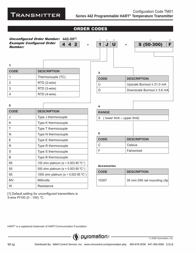
ORDER CODES
1
CODE DESCRIPTION
1 Thermocouple (TC)
2 RTD (2-wire)
3 RTD (3-wire)
4 RTD (4-wire)
3
CODE DESCRIPTION
U
D
2
CODE DESCRIPTION
J Type J thermocouple
K Type K thermocouple
T Type T thermocouple
N Type N thermocouple
E Type E thermocouple
R Type R thermocouple
S Type S thermocouple
B Type B thermocouple
85 -1)
55 -1)
95 -1)
MV Millivolts
W Resistance
1
Example Configured Order Number: 1 J U
2 3
S (50-300) F4 5Unconfigured Order Number:
4 4 2442-00[1]
4
RANGE
S ( lower limit – upper limit)
5
CODE DESCRIPTION
C Celsius
F Fahrenheit
Accessories
CODE DESCRIPTION
10307 35 mm DIN rail mounting clip
[1] Default setting for unconfigured transmitters is
® Communication Foundation
Distributed By: M&M Control Service, Inc. www.mmcontrol.com/pyromation.php 800-876-0036 847-356-0566

Transmitter
© 2006 Pyromation, Inc.
Series 442 Programmable HART® TemperatureTransmitter Specifications
TT-13316-6
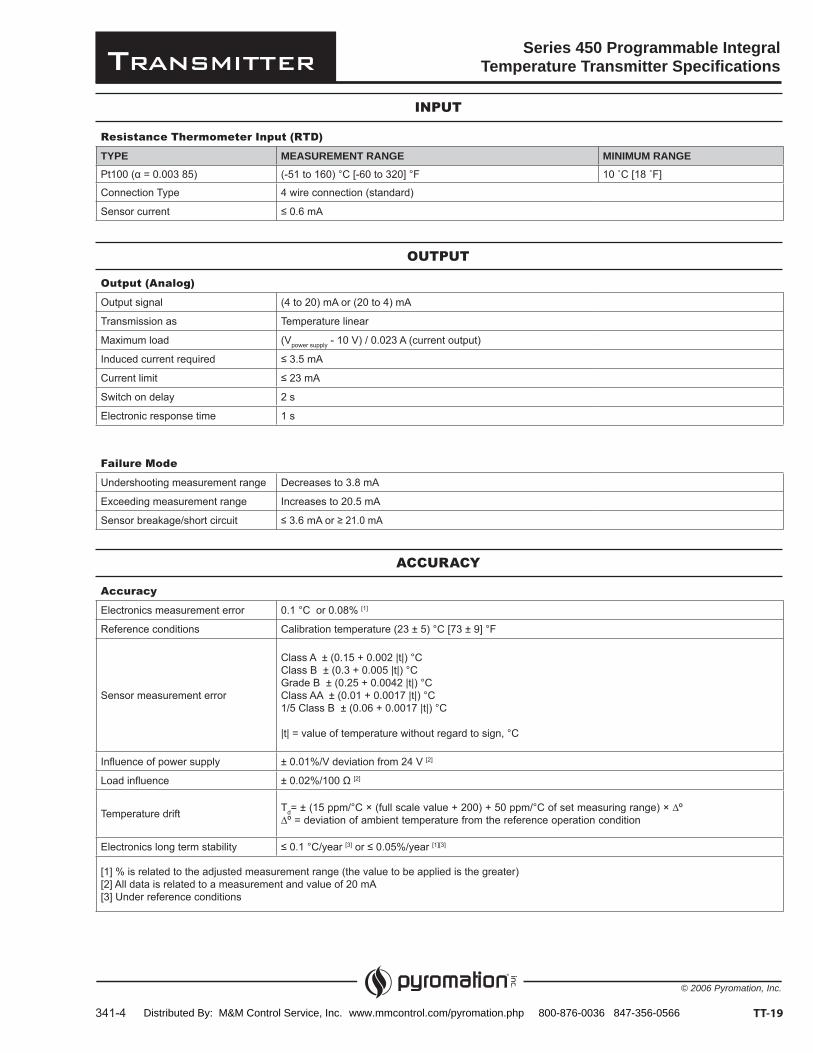
INPUT
Resistance Thermometer (RTD)
TYPE MEASUREMENT RANGE MINIMUM RANGE
oC-1)
Pt1000
oC-1)
Ni1000
Connection Type
t
Resistance ( )
TYPE MEASUREMENT RANGE MINIMUM RANGE
Thermocouples (TC)
TYPE MEASUREMENT RANGE MINIMUM RANGE
K (NiCr-Ni)
N (NiCrSi-NiSi)
Voltage (mV)
TYPE MEASUREMENT RANGE MINIMUM RANGE
®
Distributed By: M&M Control Service, Inc. www.mmcontrol.com/pyromation.php 800-876-0036 847-356-0566
Transmitter
© 2006 Pyromation, Inc.
Series 442 Programmable HART® TemperatureTransmitter Specifications
317-8TT-14
Output (Analog)
Output signal (4 to 20) mA or (20 to 4) mA
Transmission as Temperature linear, resistance linear, voltage linear
Maximum load (Vpower supply - 11.5V) / 0.022 A current output)
Digital filter 1st degree (0 to 60) s
Induced current required
Current limit
Switch on delay 4 s (during power up Ia = 3.8 mA)
Electronic response time 1 s
OUTPUT
Failure Mode
Undershooting measurement range Decrease to 3.8 mA
Exceeding measurement range Increase to 20.5 mA
Sensor breakage/short circuit [1]
[1] Not for thermocouple
Electrical Connection
Power supply Ub = (11.5 to 30) V dc, polarity protected
Galvanic isolation (In/out) Û = 2 kV ac
Allowable ripple Uss b max = 1 kHz
Reference conditions Calibration temperature (23 ± 5) oC [73 ± 9] oF
ACCURACY
Resistance Thermometer (RTD)
TYPE MEASUREMENT ACCURACY
Pt100, Ni100Pt500, Ni500Pt1000, Ni1000
± 0.2 °C or 0.08% [2]
± 0.5 °C or 0.20% [2]
± 0.3 °C or 0.12% [2]
Resistance ( )
TYPE MEASUREMENT ACCURACY MEASUREMENT RANGE
Resistance[2]
[2]
[2] % is related to the adjusted measurement range (the value to be applied is the greater)
HART® is a registered trademark of HART Communication Foundation
Distributed By: M&M Control Service, Inc. www.mmcontrol.com/pyromation.php 800-876-0036 847-356-0566

Transmitter
© 2006 Pyromation, Inc.
Series 442 Programmable HART® TemperatureTransmitter Specifications
TT-15318-8
ACCURACY (continued)
Thermocouple (TC)
TYPE MEASUREMENT ACCURACY [1]
K, J, T, E, L, UN, C, DS, B, R MoRe5-MoRe41
± 0.5 °C or 0.08%± 1.0 °C or 0.08%± 2.0 °C or 0.08%
Influence of the internal reference junction
Pt100 ± (0.30 + 0.005 |t|) °C|t| = value of temperature without regard to sign °C
Voltage (mV)
TYPE MEASUREMENT ACCURACY MEASUREMENT RANGE
Millivolt (mV) ± 20 μV or 0.08% [1] (-10 to 100) mV
General Accuracy
Influence of power supply ± 0.01%/V deviation from 24 V [2]
Load influence [2]
Temperature drift
Resistive thermometer (RTD):Td Resistive thermometer Pt100:Td
Thermocouple (TC):Td
= Deviation of the ambient temperature according to the reference condition
Long term stability [3] [1][3]
[1] % is related to the adjusted measurement range (the value to be applied is the greater)[2] All data is related to a measurement end value of 20 mA[3] Under reference conditions
INSTALLATION CONDITIONS
Ambient Conditions
Ambient temperature (-40 to 85) °C [-40 to 185] °F
Storage temperature (-40 to 100) °C [-40 to 212] °F
Climatic class To EN 60 654-1, Class C
Moisture condensation Allowable
Vibration protection 4 g / (2 to 150) Hz according to IEC 60 068-2-6
EMC immunity Interference immunity and interference emission as per EN 61 326-1 (IEC 1326)
HART® is a registered trademark of HART Communication Foundation
Distributed By: M&M Control Service, Inc. www.mmcontrol.com/pyromation.php 800-876-0036 847-356-0566

Transmitter
© 2006 Pyromation, Inc.
Series 442 Programmable HART® TemperatureTransmitter Specifications
Terminal Connections
HART® Communication on (4 to 20) mA2 (-)
1 (+)
Dimensions
Weight approximately 40 g
Materials
Terminals 15 AWG (maximum)
319-7TT-16
Power supply and current output
Sensor Connection 2-Wire 3-Wire 4-Wire
MECHANICAL CONSTRUCTION
Remote Operation
Configurable parameters
Sensor type and connection type, engineering units (°C/°F), measurement range, internal/external cold junction compensation, cable resistance compensation on 2-wire connection, fault conditioning, output signal (4 to 20) mA or (20 to 4) mA, digital filter (damping), offset, measurement point identification (8 characters), output simulation
(11.5 to 30) V dc
(4 to 20) mA
0.28 [7] 1.3 [33]
1.73 [44]0.89 [23]
0.197 [5] DIMENSIONS IN INCHES [mm]
3
4
5
6
Approvals
Unit complies with the legal requirements set forth by the EU regulations.
UL Recognized Component
General Purpose and non-incendive for use in hazardous locations Class I, Division 2 Groups A, B, C and D
marked
HART® is a registered trademark of HART Communication Foundation
Distributed By: M&M Control Service, Inc. www.mmcontrol.com/pyromation.php 800-876-0036 847-356-0566
Transmitter
© 2006 Pyromation, Inc.
Features and Benefits
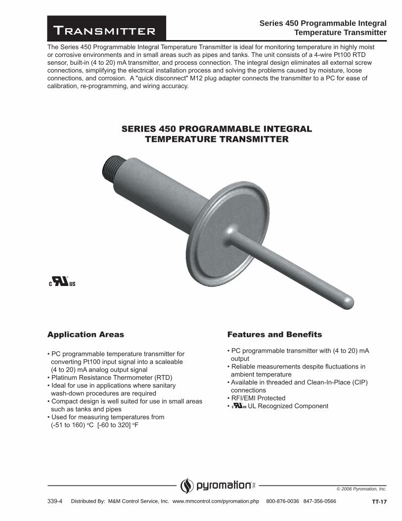
SERIES 450 PROGRAMMABLE INTEGRALTEMPERATURE TRANSMITTER
Series 450 Programmable IntegralTemperature Transmitter
TT-17
Application Areas
Distributed By: M&M Control Service, Inc. www.mmcontrol.com/pyromation.php 800-876-0036 847-356-0566
Transmitter
© 2006 Pyromation, Inc.
AUTHORIZED 74-
Series 450 Programmable IntegralTemperature Transmitter
340-4TT-18
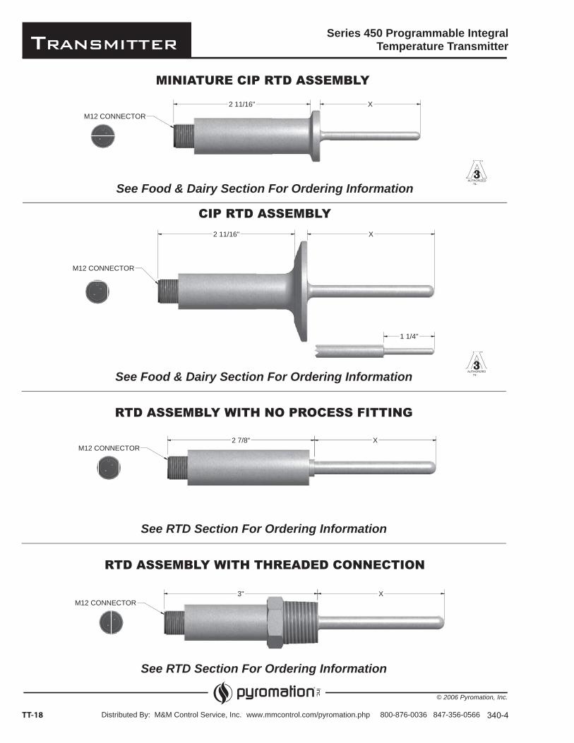
MINIATURE CIP RTD ASSEMBLY
CIP RTD ASSEMBLY
RTD ASSEMBLY WITH NO PROCESS FITTING
RTD ASSEMBLY WITH THREADED CONNECTION
See Food & Dairy Section For Ordering Information
See Food & Dairy Section For Ordering Information
See RTD Section For Ordering Information
See RTD Section For Ordering Information
AUTHORIZED 74-
X2 11/16"
M12 CONNECTOR
2 11/16" X
M12 CONNECTOR
1 1/4"
X2 7/8"M12 CONNECTOR
X3"M12 CONNECTOR
Distributed By: M&M Control Service, Inc. www.mmcontrol.com/pyromation.php 800-876-0036 847-356-0566
Transmitter
© 2006 Pyromation, Inc.
Output (Analog)
Output signal (4 to 20) mA or (20 to 4) mA
Transmission as Temperature linear
Maximum load (Vpower supply - 10 V) / 0.023 A (current output)
Induced current required
Current limit
Switch on delay 2 s
Electronic response time 1 s
Series 450 Programmable IntegralTemperature Transmitter Specifications
341-4 TT-19
Resistance Thermometer Input (RTD)
TYPE MEASUREMENT RANGE MINIMUM RANGE
Connection Type 4 wire connection (standard)
Sensor current
Failure Mode
Undershooting measurement range
Exceeding measurement range
Sensor breakage/short circuit
Accuracy
Electronics measurement error 0.1
Reference conditions
Sensor measurement error
Class A Class B Grade B Class AA
Influence of power supply
Load influence
Temperature drift Td ºº
Electronics long term stability
INPUT
OUTPUT
ACCURACY
Distributed By: M&M Control Service, Inc. www.mmcontrol.com/pyromation.php 800-876-0036 847-356-0566
Transmitter
© 2006 Pyromation, Inc.
Approvals
UL Recognized Component
3-A Sanitary Council Standard 74- (CIP sensors only)
Series 450 Programmable Integral Temperature Transmitter Specifications
342-3TT-20
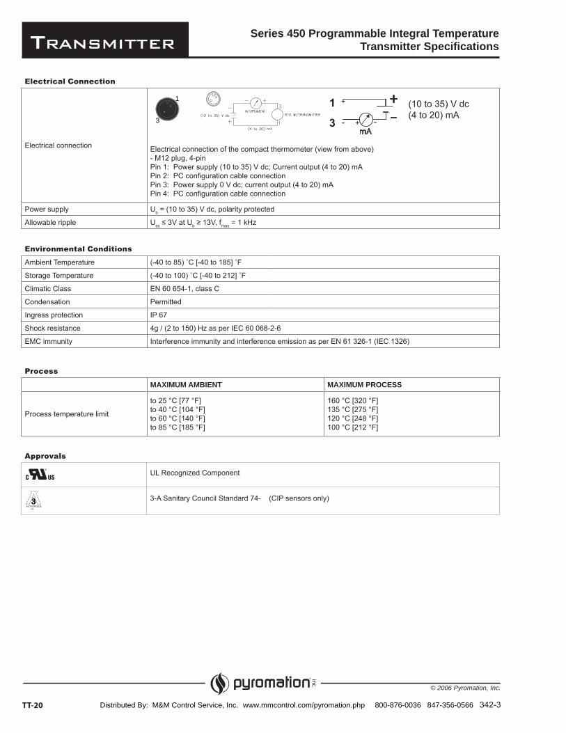
Electrical Connection
Electrical connection Electrical connection of the compact thermometer (view from above)- M12 plug, 4-pinPin 1: Power supply (10 to 35) V dc; Current output (4 to 20) mAPin 2: PC configuration cable connectionPin 3: Power supply 0 V dc; current output (4 to 20) mAPin 4: PC configuration cable connection
Power supply Ub = (10 to 35) V dc, polarity protected
Allowable ripple Uss b max = 1 kHz
Environmental Conditions
Ambient Temperature
Storage Temperature
Climatic Class EN 60 654-1, class C
Condensation Permitted
Ingress protection IP 67
Shock resistance 4g / (2 to 150) Hz as per IEC 60 068-2-6
EMC immunity Interference immunity and interference emission as per EN 61 326-1 (IEC 1326)
Process
MAXIMUM AMBIENT MAXIMUM PROCESS
Process temperature limit
(10 to 35) V dc(4 to 20) mA
AUTHORIZED 74-
1
3
Distributed By: M&M Control Service, Inc. www.mmcontrol.com/pyromation.php 800-876-0036 847-356-0566
Transmitter
© 2006 Pyromation, Inc.
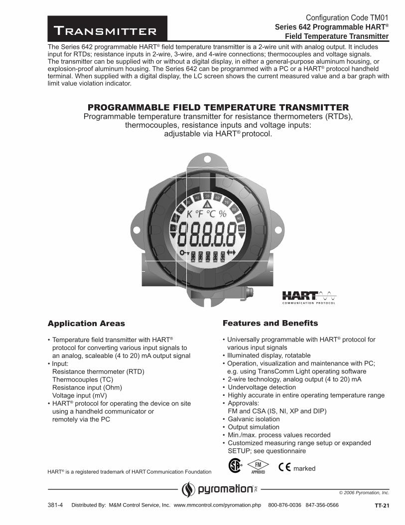
Configuration Code TM01Series 642 Programmable HART®
Field Temperature Transmitter
TT-21381-4
PROGRAMMABLE FIELD TEMPERATURE TRANSMITTERProgrammable temperature transmitter for resistance thermometers (RTDs),
thermocouples, resistance inputs and voltage inputs:adjustable via HART® protocol.
The Series 642 programmable HART®
® protocol handheld
limit value violation indicator.
Features and Benefits® protocol for
various input signals
Application Areas®
protocol for converting various input signals to an analog, scaleable (4 to 20) mA output signal
Resistance thermometer (RTD) Thermocouples (TC)
Voltage input (mV)® protocol for operating the device on site
using a handheld communicator or
markedHART® is a registered trademark of HART Communication Foundation
Distributed By: M&M Control Service, Inc. www.mmcontrol.com/pyromation.php 800-876-0036 847-356-0566

Transmitter
© 2006 Pyromation, Inc.
- -
Configuration Code TM01Series 642 Programmable HART®
Field Temperature Transmitter
-
382-5TT-22
ORDER CODES
1-2 Input Type
CODE DESCRIPTION
00 [1]
1 Thermocouple (TC) or millivolt
2 RTD (2-wire) or resistance
3 RTD (3-wire) or resistance
4 RTD (4-wire) or resistance
1-4 Failure Mode
CODE DESCRIPTION
U
D
1-3 Sensor Type
CODE DESCRIPTION
J Type J thermocouple
K Type K thermocouple
T Type T thermocouple
N Type N thermocouple
E Type E thermocouple
R Type R thermocouple
S Type S thermocouple
B Type B thermocouple
85 -1)
55 500 ohm platinum -1)
95 -1)
MV Millivolts
W Resistance
1-0
Example Order Number: D1-2 1-3
S(0-200) C1-5 1-6
642A
1-5 Range
CODE DESCRIPTION
S (lower limit – upper limit)
1-6 Unit of Measure
CODE DESCRIPTIONC CelsiusF FahrenheitK Kelvin
Accessories
CODE DESCRIPTION
10321 Pipe mounting bracket for use on pipes
1-1
1-0 Transmitter Type
CODE DESCRIPTION® Field Transmitter with general-
purpose aluminum housing
642C
® Field Transmitter with
642F
® Field Transmitter with general-
3 85 U1-4
1-1 Options
CODE DESCRIPTION
T Solid cover
D Glass cover with digital display
[1] Default setting for unconfigured transmitter is 3-wire Pt100 (0 - 100) °C
® Communication Foundation
Distributed By: M&M Control Service, Inc. www.mmcontrol.com/pyromation.php 800-876-0036 847-356-0566

Transmitter
© 2006 Pyromation, Inc.
Series 642 Programmable HART® Field Temperature Transmitter Specifications
TT-23383-3
INPUT
Resistance Thermometer (RTD)
TYPE STANDARDS MEASUREMENT RANGE MINIMUM RANGEoC-1)
Pt200
Pt1000
ASTM E1137
SAMA
Ni100 Ni1000
Edison Curve
Cu100 (
GOST
Polynomial RTDPt100 (Callendar - van Dusen)
Connection type
Sensor current
Resistance ( )
TYPE MEASUREMENT RANGE MINIMUM RANGE
Thermocouples (TC) (ASTM E230)
TYPE MEASUREMENT RANGE MINIMUM RANGE
E (NiCr-CuNi)
K (NiCr-Ni)
N (NiCrSi-NiSi)
T (Cu-CuNi)U (Cu-CuNi)
Cold junction
Cold junction accuracy
10 k
Voltage (mV)
TYPE MEASUREMENT RANGE MINIMUM RANGE
Millivolt (mV) (-20 to 100) mV
HART®
Distributed By: M&M Control Service, Inc. www.mmcontrol.com/pyromation.php 800-876-0036 847-356-0566

Transmitter
© 2006 Pyromation, Inc.
Series 642 Programmable HART® FieldTemperature Transmitter Specifications
384-3TT-24
[1] % relates to the set span. Accuracy = digital + D/A accuracy
Output (Analog)
Output signal Analog (4 to 20) mA or (20 to 4) mA
Transmission as Temperature linear, resistance linear, voltage linear
Maximum load (Vpower supply - 11V) / 0.022 A (current output)
Digital filter 1st degree (0 to 60) s
Induced current required
Current limit
Switch on delay 4 s (during switch-on operation Ia = 4 mA)
Response time 1 s
OUTPUT
Failure Mode
Undershooting measurement range Decrease to 3.8 mA
Exceeding measurement range
Sensor breakage/short circuit
Electrical Connection
Power supply Ub = 11 to 40 V (8 to 40 without display), reverse polarity protected
Cable entry Three 1/2" NPT openings
Allowable ripple Uss b max = 1 kHz
Reference conditions oC [73.4 ± 9] oF
ACCURACY
Resistance Thermometer (RTD)
TYPE MEASUREMENT ACCURACY - DIGITAL MEASUREMENT ACCURACY - D/A[1]
Cu100, Pt100, Ni100, Ni120
Cu10, Pt200
± 0.2 °C [0.36 °F] ± 0.6 °C [1.08 °F] ± 0.4 °C [0.72 °F] ± 2 °C [3.6 °F]
± 0.02% ± 0.02%± 0.02% ± 0.02%
Resistance ( )
TYPE MEASUREMENT ACCURACY - DIGITAL MEASUREMENT ACCURACY - D/A[1] MEASUREMENT RANGE
Resistance± 0.08 ± 0.02%
± 1.6 ± 0.02%
Thermocouple (TC)
TYPE MEASUREMENT ACCURACY - DIGITAL MEASUREMENT ACCURACY - D/A[1]
K, J, T, E, L, UN, C, DS, B, R
Typical ± °C [0.9 °F] Typical ± 1 °C [0.18 °F] Typical ± 2 °C [3.6 °F]
± 0.02%± 0.02%± 0.02%
Voltage (mV)
TYPE MEASUREMENT ACCURACY - DIGITAL MEASUREMENT ACCURACY - D/A[1] MEASUREMENT RANGE
Voltage ± 20 μV ± 0.02% (20 to 100) mV
HART® is a registered trademark of HART Communication Foundation
Distributed By: M&M Control Service, Inc. www.mmcontrol.com/pyromation.php 800-876-0036 847-356-0566
Transmitter
© 2006 Pyromation, Inc.
Series 642 Programmable HART® FieldTemperature Transmitter Specifications
TT-25385-3
[1] % is related to the adjusted measurement range (the value to be applied is the greater)
ACCURACY (continued)
Physical input range of the sensors
TYPE MEASUREMENT ACCURACY[1]
Cu10, Cu50, Cu100, polynomial RTD, Pt50, Pt100, Ni100, Ni120
(10 to 2000) Pt200, Pt500, Pt1000, Ni1000
(-20 to 100) mV Thermocouple type: C, D, E, J, K, L, N
(-5 to 30) mV Thermocouple type: B, R, S, T, U
General
Repeatability 0.03% of the physical input range (15 Bit)Resolution A/D conversion: 18 Bit
Load influence
Long term stability Date under reference conditions. % relates to the set span. The larger value applies.
INSTALLATION CONDITIONS
Ambient Conditions
Ambient temperature With display: NOTE: The display can react slowly for temperature < -20 C [< -4
Storage temperature
Allowable Altitude 6500 ft. above sea level
Climatic class As per EN 60 654-1, Class C
Moisture condensation Allowable
Shock and vibration protection 3 g / (2 to 150) Hz according to IEC 60 068-2-6
EMC immunity Interference immunity and interference emission as per EN 61 326-1 (IEC 1326)(0.08 to 2) GHz 10 V/m; (1.4 to 2) GHz 30 V/m to EN 61 000-4-3
Protection (when specified)
Temperature Drift
Total temperature drift = input temperature drift + output temperature drift
Effect on the accuracy when ambient temperature changes by 1 C [1.8
Input (10 to 400) 0.002% of measured value
Input (10 to 2000) 0.002% of measured value
Input (-20 to 100) mV typ. 0.002% of measured value(maximum value = 1.5 x typical)
Input (5 to 30) mV typ. 0.002% of measured value(maximum value = 1.5 x typical)
Output (4 to 20) mA typ. 0.002% of measured value(maximum value = 1.5 x typical)
HART® is a registered trademark of HART
Distributed By: M&M Control Service, Inc. www.mmcontrol.com/pyromation.php 800-876-0036 847-356-0566

Transmitter
© 2006 Pyromation, Inc.
Series 642 Programmable HART® FieldTemperature Transmitter Specifications
386-3TT-26
INTERFACE
Operating Elements
No operating elements are present directly on the display. The device parameters of the field transmitter are configured using the handheld communicator or a PC with HART® Modem and operating software TransComm Light.
°C°F %K10
0
20
3040 50 60
70
80
90
100
!
Display Elements
LC display of the field transmitter (illuminated, can be rotated in 90° increments)
Item 1: Bar graph display in 10% increments with indicators for overranging /
underranging
Item 2: ‘Caution’ display
Item 3: Unit display K, °F, or °C or %
Item 4: Measured value display (digit height 20.5 mm / 0.81 “)
Item 5: Status and information display
Item 6: ‘Communication’ display
Item 7: ‘Programming disabled’ display
Remote Operation
Interface HART® communication via transmitter power supply
Configurable device parameters
Sensor type and connection type, engineering units (°C/°F), measurement ranges, internal/external cold junction compensation of wire resistance with 2-wire connection, failure mode, output signal (4 to 20) mA (20 to 4) mA, digital filter (damping), offset, TAG+descriptor (8+16 characters), output simulation, customized linearization, recording of min./max process value, analog output: Option: customized linearization
STANDARDS
Approvals
Unit complies with the legal requirements set forth by the EU regulations.
Intrinsically safe and non-incendive or explosion proof for hazardous locations Class I, Division 1 and 2, Groups A, B, C and D
Other standards and guidelines
IEC 60 529: Degrees of protection through housing (IP code)IEC 61 010: Protection measures for electrical equipment for measurement, control, regulation and laboratory proceduresIEC1326: Electromagnetic compatibility (EMC requirements)
marked
HART® is a registered trademark of HART Communication Foundation
Distributed By: M&M Control Service, Inc. www.mmcontrol.com/pyromation.php 800-876-0036 847-356-0566
Transmitter
© 2006 Pyromation, Inc.
Series 642 Programmable HART® FieldTemperature Transmitter Specifications
387-4 TT-27
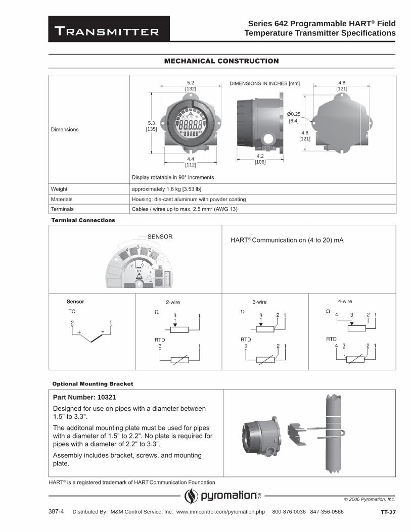
MECHANICAL CONSTRUCTION
Dimensions
Display rotatable in 90° increments
Weight approximately 1.6 kg [3.53 lb]
Materials Housing: die-cast aluminum with powder coating
Terminals Cables / wires up to max. 2.5 mm2 (AWG 13)
Optional Mounting Bracket
Part Number: 10321Designed for use on pipes with a diameter between 1.5" to 3.3".
The additonal mounting plate must be used for pipes with a diameter of 1.5" to 2.2". No plate is required for pipes with a diameter of 2.2" to 3.3".
Assembly includes bracket, screws, and mounting plate.
Terminal Connections
HART® Communication on (4 to 20) mA
4.4[112]
5.2[132]
5.3[135]
4.2[106]
4.8[121]
4.8[121]
0.25[6.4]
DIMENSIONS IN INCHES [mm]
HART® is a registered trademark of HART Communication Foundation
Distributed By: M&M Control Service, Inc. www.mmcontrol.com/pyromation.php 800-876-0036 847-356-0566
Transmitter
© 2006 Pyromation, Inc.
Series 642 Field Temperature Transmitter
388-2TT-28
SensorTC ( ) B ( ) C ( ) D ( ) E ( ) J
( ) K ( ) L ( ) N ( ) R ( ) S( ) T ( ) U
RTD ( ) Pt100 ( ) Pt500 ( ) Pt1000( ) Ni100 ( ) Ni500 ( ) Ni1000
( ) 2-wire
( ) mV
( ) 3-wire
( ) (10 to 400) Ohm
( ) 4-wire
( ) (10 to 2000) Ohm
Unit ( ) °C ( ) °F ( ) K ( ) mV ( ) Ohm
Range Lower limit
Upper limit
S1
S1
Note:
Expanded setup
Reference junction/TC only ( ) internal ( ) external
Compensation wire resistance
Failure mode ( ) < 3.6 mA ( ) > 21.0 mA
Output ( ) ( 4 to 20 ) mA
( ) 50 Hz
( ) ( 20 to 4 ) mA
( ) 60 Hz
Filter
Offset
Line voltage filter
TAG
DESCRIPTION16 characters max.
Configuration sheet for Series 642 temperature transmitterFor customer specific setup
.
.
.
(0 to 60) s
Must meet minimum space requirements
(-10 to 10) ºC [-18 to 18] ºF
(0 to 80) ºC (32 to 17) ºF
(0 to 30) Ohm
Distributed By: M&M Control Service, Inc. www.mmcontrol.com/pyromation.php 800-876-0036 847-356-0566
Transmitter
© 2013 Pyromation, Inc.
Configuration Code TM01T82 Programmable HART®
Temperature Transmitter
TT-29466-1
PROGRAMMABLE DUAL INPUT TEMPERATURE TRANSMITTERProgrammable temperature transmitter for resistance thermometers (RTDs),
thermocouples, resistance inputs and voltage inputs:adjustable via HART® protocol.
The T82 programmable HART®
The T82 can be programmed using a HART®
Features and Benefits® protocol for
various input signals
Application Areas
and HART® protocol for converting various input signals to an analog, scaleable (4 to 20) mA output signal
Resistance thermometer (RTD) Thermocouples (TC)
Voltage input (mV)® protocol for operating the device on site
using a handheld communicator
markedHART®
Distributed By: M&M Control Service, Inc. www.mmcontrol.com/pyromation.php 800-876-0036 847-356-0566
Transmitter
© 2013 Pyromation, Inc.
---- -
Configuration Code TM01T82 Programmable HART®
Temperature Transmitter
-
467-1TT-30
ORDER CODES
1-5 Failure Mode
CODE DESCRIPTION
U
D
1-2 Sensor Input Channel 1
CODE DESCRIPTION
J
K
T
N
E
R
S
B
85 -1)
55 -1)
95 -1)
1-0Example Order Number: 33 S(0-200) C
1-5 1-6
36T82-D10
1-6 Range
CODE DESCRIPTION
S
1-7 Unit of Measure
CODE DESCRIPTIONC CelsiusF Fahrenheit
1-1
1-0 Transmitter Type
CODE DESCRIPTION
purpose screw-cover housing
851-4
®
1-1 Con guration Input
CODE DESCRIPTION00
4T
TT
1-3 Sensor Input Channel 2
CODE DESCRIPTION
00 No second channel
J
K
T
N
E
R
S
B
85 -1)
55 -1)
95 -1)
1-4 Input Set-ups
CODE DESCRIPTION
B
C
D
E
85 E U1-6 1-7
Distributed By: M&M Control Service, Inc. www.mmcontrol.com/pyromation.php 800-876-0036 847-356-0566
Transmitter
© 2013 Pyromation, Inc.
T82 Programmable HART® Temperature Transmitter Specifications
TT-31468-1
INPUT
Resistance Thermometer (RTD)
TYPE STANDARD MEASUREMENT RANGE MINIMUM RANGEoC-1)
Pt200
Pt1000
Ni100 Ni120 IPTS-68
Pt100 (Callendar van Dusen)Nickel polynomialCopper polynomial
The measuring range limits are specified by entering the limit values that depend on the coefficients A to C and RO
Resistance ( )
TYPE MEASUREMENT RANGE MINIMUM RANGE
Thermocouples (TC)
TYPE STANDARD MEASUREMENT RANGERECOMMENDED TEMPERATURE RANGE
MINIMUM RANGE
E (NiCr-CuNi)
K (NiCr-Ni)N (NiCrSi-NiSi)
S (PtRh10-Pt)T (Cu-CuNi)
U (Cu-CuNi)
Cold junction
resistance 10 k
Voltage (mV)
TYPE MEASUREMENT RANGE MINIMUM RANGE
Millivolt (mV) (-20 to 100) mV
HART®
Distributed By: M&M Control Service, Inc. www.mmcontrol.com/pyromation.php 800-876-0036 847-356-0566

Transmitter
© 2013 Pyromation, Inc.
T82 Programmable HART® Temperature Transmitter Specifications
469-1TT-32
[1] Using HART® transmitted measured value[2] % refers to the set span. Accuracy of current output = digital + D/A accuracy
Output (Analog)
Output signal Analog (4 to 20) mA or (20 to 4) mA
Transmission as Temperature linear, resistance linear, voltage linear
Maximum load (Ub max - 11V) / 0.023 A (current output)
Digital filter 1st degree (0 to 120) s
Minimum current required 3.5 mA, multidrop mode 4 mA
Current limit
Switch on delay 10 s (during switch-on operation Ia 3.8 mA)
Response time
Resistance thermometer (RTD) 0.9 to 1.2 s (depends on the connection method 2/3/4-wire)
Thermocouples (TC) 0.7 s
Reference temperature 0.5 s
OUTPUT
Failure Mode
Underranging Linear drop from 4.0 mA to 3.8 mA
Overranging Linear increase from 20.0 mA to 20.5 mA
Failure, e.g. sensor breakage; sensor short circuit
Electrical Connection
Supply Voltage locationsEntry
Residual Uss b max
Reference conditionsCalibration temperature (25 ± 5) oC [77 ± 9] oFSupply voltage: 24 V dc4-wire circuit for resistance adjustment
ACCURACY
Resistance Thermometer (RTD)
TYPE MEASUREMENT ACCURACY - DIGITAL[1] MEASUREMENT ACCURACY - D/A[2]
0.1 °C [0.18 °F] 0.3 °C [0.54 °F] 0.2 °C [0.36 °F] 1.0 °C [1.8 °F]
0.03% 0.03%0.03% 0.03%
Resistance ( )
TYPE MEASUREMENT ACCURACY - DIGITAL[1] MEASUREMENT ACCURACY - D/A[2] MEASUREMENT RANGE
Resistance± 0.04 0.03%
± 0.8 0.03%
Thermocouple (TC)
TYPE MEASUREMENT ACCURACY - DIGITAL[1] MEASUREMENT ACCURACY - D/A[2]
K, J, T, E, L, UN, C, DS, B, R
0.25 °C [0.45 °F] 0.5 °C [0.9 °F] 1.0 °C [1.8 °F]
0.03%0.03%0.03%
Voltage (mV)
TYPE MEASUREMENT ACCURACY - DIGITAL[1] MEASUREMENT ACCURACY - D/A[2] MEASUREMENT RANGE
Voltage ± 10 μV 0.03% (-20 to 100) mV
HART® is a registered trademark of HART Communication Foundation
Distributed By: M&M Control Service, Inc. www.mmcontrol.com/pyromation.php 800-876-0036 847-356-0566

Transmitter
© 2013 Pyromation, Inc.
T82 Programmable HART®
Temperature Transmitter Specifications
TT-33470-1
ACCURACY (continued)
Physical input range of the sensors
Cu50, Cu100, polynomial RTD, Pt50, Pt100, Ni100, Ni120
(10 to 2000) Pt200, Pt500, Pt1000
(-20 to 100) mV Thermocouple type: B, C, D, E, J, K, L, N, R, S, T, U
General
Load influence
INSTALLATION CONDITIONS
Ambient Conditions
documentation)Storage temperature
Altitude
Humidity
2 kV
10 V
Protection
Influence of ambient temperaure (temperature drift)
Total temperature drift = input temperature drift + output temperature drift
μV
Output (4 to 20) mA
HART®
Distributed By: M&M Control Service, Inc. www.mmcontrol.com/pyromation.php 800-876-0036 847-356-0566

Transmitter
© 2013 Pyromation, Inc.
Display Elements
Item 1: Displays the TAG
Item 2: 'Communication' symbol
Item 3: Unit display
Item 4: Measured value display
Item 5: Value/channel display S1, S2,
DT, PV, I, %
Item 6: 'Configuration locked' symbol
Item 7: Status signals
T82 Programmable HART®
Temperature Transmitter Specifications
471-1TT-34
INTERFACE
Remote Operation
Interface HART® (Version 6) communication via transmitter power supply
Configurable device parameters
Sensor type and connection type, engineering units (°C/°F), measurement ranges, internal/external cold junction compensation of wire resistance with 2-wire connection, failure mode, output signal (4 to 20) mA (20 to 4) mA, digital filter (damping), offset, TAG+descriptor (8+16 characters), output simulation, analog output: option: customized linearization
APPROVALS
Approvals
Unit complies with the legal requirements set forth by the EU regulations.
Intrinsically safe and non-incendive Class I, Division 1 and 2, Groups A, B, C and D
marked
HART® is a registered trademark of HART Communication Foundation
1
2
345
6
7
Distributed By: M&M Control Service, Inc. www.mmcontrol.com/pyromation.php 800-876-0036 847-356-0566
Transmitter
© 2013 Pyromation, Inc.
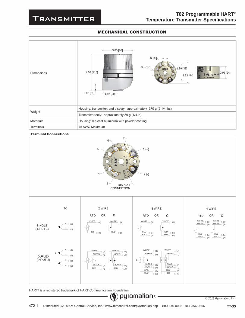
T82 Programmable HART®
Temperature Transmitter Specifications
472-1 TT-35
MECHANICAL CONSTRUCTION
Dimensions
WeightHousing, transmitter, and display: approximately 970 g (2 1/4 lbs)
Transmitter only: approximately 50 g (1/4 lb)
Materials Housing: die-cast aluminum with powder coating
Terminals 15 AWG Maximum
Terminal Connections
HART® is a registered trademark of HART Communication Foundation
4.53 [115]
0.82 [21]
3.80 [96]
1.97 [50]
1.30 [33]
1.73 [44]
0.27 [7]
0.18 [4]
0.95 [24]
DISPLAYCONNECTION
3
4
5
67
1 (+)
2 (-)
+
-
+
-
(7)
(6)
(6)
(5)
-
(5)
(6)
+
2
1
TC
SINGLE(INPUT 1)
DUPLEX(INPUT 2)
RED
BLACK
WHITE
GREEN
WHITE
RED (6)
(4)
(3)
(6)
(4)
(6)
RED
GREEN
WHITE
(6)
(6)
(4)
(6)
(3)
(4)WHITE
BLACK
RED
21 21
RTD
2 WIRE
OR
REDRED
BLACKBLACK
WHITE
GREEN (3)
(4)
(6)(7)
(5)
(4)
(6)
REDRED
WHITE
(6)(5)
(7)(6)
WHITE
REDRED
(4)
RED
BLACK
RED
BLACK
(5)(6)
GREEN
WHITE (4)
(3)
(6)(5)
21 21
3 WIRE
RTD OR
(5)(6)
REDRED
(4)WHITE
(6)(5)
REDRED
(4)WHITEWHITE WHITE(3) (3)
4 WIRE
RTD OR
Distributed By: M&M Control Service, Inc. www.mmcontrol.com/pyromation.php 800-876-0036 847-356-0566


