
Road & Bridge Design Publications
Monthly Update – December 2017
1
Revisions for the month of December are listed and displayed below. New special details will be included in projects submitted for the April letting as is stated on the special detail index sheets. E-mail Road related questions on these changes to [email protected]. E-mail Bridge related questions to [email protected]. Special Details R-28-J: Sidewalk Ramp & Detectable Warning Details: Eliminated a portion of the “*” note on sheets one through four in favor of a note in the note section. Road Design Manual 14.70: Design Project Record: Moved this section to 14.69, which was empty. 14.71: Plan Revisions: Moved this section to 14.70 and inserted a “Contract Modifications section. 14.72: Post-Construction Review Meeting: Replaced section contents with updated material. 14.72.01: Recommendations and Authorizations: Deleted this section. Bridge Design Manual 7.02.17 (LFD & LRFD), 8.07.07 F. (LFD & LRFD), 8.09.04 Y. (LFD & LRFD) and 12.07.07: Deleted the “A” designation from AMS-STD-595A; the color shall be based on the current version of specification. Bridge Design Guides 6.20.04: Updated distance to EA08 bars, that run through beam end, to allow for tube placement tolerances and maintain reinforcement cover on EM bars in backwall. 6.29.08A & 6.29.09A: Included dimension between holes for adhesive anchored bars. 8.21.03: Clarified pile points and end plates. Deleted note regarding points for fluted shells.

Road & Bridge Design Publications
Monthly Update – December 2017
2
Updates to MDOT Cell Library, Bridge Auto Draw Program, etc., may be required in tandem with some of this month's updates. Until such updates to automated tools can be made, it is the designer's/detailer's responsibility to manually incorporate any necessary revisions to notes and plan details to reflect these revisions.

Index to Special Details
12-26-2017
SPECIAL DETAIL
NUMBER
NUMBER
OF SHEETS
TITLE
CURRENT
DATE
21
2 GUARDRAIL AT INTERSECTIONS 3-14-16
24
8
GUARDRAIL ANCHORED IN BACKSLOPE TYPES 4B, 4T, & 4MGS-8 4-25-16
99
2
CHAIN LINK FENCE WITH WIRE ROPE 9-22-14
R-1-G 9
DRAINAGE STRUCTURES 6-15-16
*R-28-J 7
SIDEWALK RAMP AND DETECTABLE WARNING DETAILS 12-11-17
R-39-K 5
TRANSVERSE PAVEMENT JOINTS 9-25-17
R-53-A 22
TEMPORARY CONCRETE BARRIER LIMITED DEFLECTION 8-14-15
R-56-F 8
GUARDRAIL MEDIAN OBJECT PROTECTION 9-8-16
R-60-J 17
GUARDRAIL TYPES A, B, BD, T, TD, MGS-8, & MGS-8D 7-26-17
R-61-H 20
GUARDRAIL APPROACH TERMINAL TYPES 1B & 1T (SRT, FLEAT, & X-Lite Fl) 2-2-17
R-62-H 14
GUARDRAIL APPROACH TERMINAL TYPES 2B & 2T (SKT, ET-Plus, & X-Lite T) 4-3-17
R-63-C 16
GUARDRAIL APPROACH TERMINAL TYPES 3B & 3T 3-15-16
R-66-E 4
GUARDRAIL DEPARTING TERMINAL TYPES B, T, & MGS 4-27-16
R-67-G 7
GUARDRAIL ANCHORAGE, BRIDGE, DETAILS 8-9-17
R-72-D 11
W-BEAM BACKED GUARDRAIL & GUARDRAIL LONG SPAN INSTALLATIONS 5-11-16
R-73-F 6
GUARDRAIL OVER BOX OR SLAB CULVERTS 3-15-16
R-112-I 9
SHOULDER AND CENTER LINE CORRUGATIONS 12-12-16
R-126-I 5
PLACEMENT OF TEMPORARY CONCRETE & STEEL BARRIER 8-25-15
R-127-F 8
DELINEATOR INSTALLATIONS 8-8-17
* Denotes New or Revised Special Detail to be included in projects for (beginning with) the April letting.
Note: Former Standard Plans IV-87, IV-89, IV-90, and IV-91 Series, used for building cast-in-place concrete head walls for elliptical and circular pipe culverts, are now being replaced with plans that detail each specific size. The Special Structures Unit will provide these full sized special details for inclusion in construction plans for MDOT jobs. To assure prompt delivery, requests must be made in advance.
Former Standard Plans IV-93 and IV-94 series have been replaced with precast concrete box & three-sided culverts as per the 2012 Standard Specifications for Construction.

Index to Bridge Detail Sheets
12-26-2017
DETAIL NUMBER
NUMBER
OF SHEETS
TITLE
CURRENT
DATE
B-22-E
4 BRIDGE RAILING, THRIE BEAM RETROFIT (R4 TYPE RAILING) 3-15-16
B-23-F
4 BRIDGE RAILING, THRIE BEAM RETROFIT (OPEN PARAPET RAILING) 3-15-16
B-101-G
2 DRAIN CASTING ASSEMBLEY DETAILS 2-8-16
EJ3AB
1 or 2
EXPANSION JOINT DETAILS 2-10-16
EJ4O
1 or 2
EXPANSION JOINT DETAILS 2-10-16
PC-1M
1
PRESTRESSED CONCRETE I-BEAM DETAILS 8-23-17
PC-2H
1
70" PRESTRESSED CONCRETE I-BEAM DETAILS 8-23-17
PC-4F
1
PRESTRESSED CONCRETE 1800 BEAM DETAILS 8-23-17
* Denotes New or Revised Special Detail to be included in projects for
(beginning with) the April letting. Note: Details EJ3AA & EJ4N are interactive, i.e. designers and detailers choose details
based upon railing type and angle of crossing. Place all details appropriate for the project, structure specific information, and the Expansion Joint Device quantity on the sheet. The sheet shall then be added to the plans as a normal plan sheet.
Detail PC-1L, PC-2G and PC-4E shall have structure specific information and quantities added to the sheet. The sheet shall then be added to the plans as a normal plan sheet.

A
A
A
MAXIMUM SIDE FLARE SLOPE
REDUCED TO ACCOMMODATE
FULL CURB HEIGHT MAY BE
** R
AMP
SIDEWALK
SIDE FLARE
SIDE FLARE
5' MI
N.
SIDEWALK
5' MIN.
SIDE FLARE
SIDE FLARE
** RAMP
SIDEWALK RAMP TYPE F
(FLARED SIDES, TWO RAMPS SHOWN)
(SEE NOTES)
SLOPE
10% MAX.
(SEE NOTES)
SLOPE
10% MAX.
(SEE N
OTES)SLOPE10% MAX.
(SEE N
OTES)SLOPE10% MAX.
B.L.T.
W.K.P. 7
DETECTABLE WARNING DETAILS
SIDEWALK RAMP AND
1
A
(SEE NOTES)
(SEE
NOTES)
R-28-J
A
A
OBSTRUCTION
PERMANENT
** R
AMP
SIDEWALK RAMP TYPE R
5' MI
N.
SIDEWALK
SIDEWALK
(ROLLED SIDES)
ROLLED CURB
"NON-WALKING" AREA
(SEE
NOTES)
(SEE NOTES)
24" ACROSS FULL WIDTH
DETECTABLE WARNING SURFACE
(SEE NOTES)
24" ACROSS FULL WIDTH
DETECTABLE WARNING SURFACE
(SEE NOTES)
24" ACROSS FULL WIDTH
DETECTABLE WARNING SURFACE
* LANDING
5% - 7% (8.3% MAXIMUM). SEE NOTES.
** MAXIMUM RAMP CROSS SLOPE IS 2.0%, RUNNING SLOPE
* LANDING
DEPARTMENT DIRECTOR MICHIGAN DEPARTMENT OF TRANSPORTATION
OF
SHEET
PLAN DATEF.H.W.A. APPROVALCHECKED BY:
DRAWN BY:
Michigan Department of Transportation
BUREAU OF DEVELOPMENT STANDARD PLAN FOR
APPROVED BY:
APPROVED BY:
Kirk T. Steudle
BY
PREPARED
DESIGN DIVISION
DIRECTOR, BUREAU OF FIELD SERVICES
DIRECTOR, BUREAU OF DEVELOPMENT
12-11-2017
SEE NOTES.
OF TRAVEL. LANDING MINIMUM DIMENSIONS 5' x 5'.
* MAXIMUM LANDING SLOPE IS 2.0% IN EACH DIRECTION

72
DETECTABLE WARNING DETAILS
SIDEWALK RAMP AND
R-28-J
MICHIGAN DEPARTMENT OF TRANSPORTATION
OF
SHEET
PLAN DATEF.H.W.A. APPROVAL
BUREAU OF DEVELOPMENT STANDARD PLAN FOR
ADJACENT CURB & GUTTER
REINFORCEMENT AS IN
SECTION A-A
PAVEMENT
1" EXPANSION JOINT
GRADE BREAK
(8.3% MAXIMUM) SEE NOTES
RAMP SLOPE 5% - 7%
A SIDEWALK
SIDEWALK RAMP TYPE RF
5' MI
N.
SIDE FLARE
(ROLLED / FLARED SIDES)
** R
AMP
(SEE N
OTES)SLOPE10% MAX.
WALKING AREA
"NON-WALKING" AREA
A
(SEE
NOTES)
ROLLED CURB
(SEE NOTES)
24" ACROSS FULL WIDTH
DETECTABLE WARNING SURFACE
2" MAX.24" ACROSS FULL WIDTH (SEE NOTES)
DETECTABLE WARNING SURFACE
RAMP RUN
* LANDING
SHALL BE AS CALLED FOR ON THE PLANS
RAMP AND LANDING SLAB THICKNESSES
B1
B2
B3
D1
D2
D3
C1
C2
C3
C4
C5
C6
F1
F2
F3
F4
F5
F6
A B
CURB TYPE
1
1
ƒ
ƒ
1
1
1
1
1
1
1
1
•
ƒ
ƒ
ƒ
ƒ
ƒ
ƒ
•
•
•
•
•
•
•
•
•
•
•
•
•
ƒ
ƒ
•
•
STANDARD PLAN R-30-SERIES
FOR CURB TYPES SEE
OPENING
CURB RAMP
* LANDING
(INCHES)
RISE
MAXIMUM
WITH THE GUTTER PAN
PAVEMENT SHALL END FLUSH
(TYPICAL ALL RAMP TYPES)
THE RAMP OPENING.
MAXIMUM COUNTER SLOPE ACROSS
CROSS SECTION TO PROVIDE 5.0%
*** TRANSITION ADJACENT GUTTER PAN
WITH BACK OF CURB
RAMP SHALL END FLUSH
*** 5.0% MAX.
A B
SECTION THROUGH CURB RAMP OPENING
MAXIMUM RISE B
NOT TO EXCEED
MATCH RAMP SLOPE
12-11-2017
5% - 7% (8.3% MAXIMUM). SEE NOTES.
** MAXIMUM RAMP CROSS SLOPE IS 2.0%, RUNNING SLOPE
SEE NOTES.
OF TRAVEL. LANDING MINIMUM DIMENSIONS 5' x 5'.
* MAXIMUM LANDING SLOPE IS 2.0% IN EACH DIRECTION

SIDEWALK RAMP TYPE M
(MEDIAN ISLAND)
5' MI
N.
SIDEWALK RAMP TYPE P
(PARALLEL RAMP)
5' MI
N.
DO NOT USE IN AREAS WHERE PONDING MAY OCCUR
SIDEWALK
SIDEWALK
** RAMP
** R
AMP
"NON-WALKING" AREA
SIDEWALK RAMP TYPE C
5' MI
N.
SIDEWALK
SIDEWALK
** RAMP
** R
AMP
"NON-WALKING" AREA
"NON-WALKING" AREA
73
MEDIAN WIDTH
DETECTABLE WARNING DETAILS
SIDEWALK RAMP AND
(COMBINATION RAMP)
ROLLED CURB
(SEE
NOTES)
(SEE
NOTES)
(SEE NOTES)
24" ACROSS FULL WIDTH
DETECTABLE WARNING SURFACE
(SEE NOTES)
24" ACROSS FULL WIDTH
DETECTABLE WARNING SURFACE
R-28-J
MICHIGAN DEPARTMENT OF TRANSPORTATION
OF
SHEET
PLAN DATEF.H.W.A. APPROVAL
BUREAU OF DEVELOPMENT STANDARD PLAN FOR
* LANDING
* LANDING
DETECTABLE WARNING IS REQUIRED.
IS AT LEAST 6'-0". OTHERWISE NO
ACROSS FULL WIDTH IF MEDIAN WIDTH
DETECTABLE WARNING SURFACE 24"
12-11-2017
5% - 7% (8.3% MAXIMUM). SEE NOTES.
** MAXIMUM RAMP CROSS SLOPE IS 2.0%, RUNNING SLOPE
SEE NOTES.
OF TRAVEL. LANDING MINIMUM DIMENSIONS 5' x 5'.
* MAXIMUM LANDING SLOPE IS 2.0% IN EACH DIRECTION

74
DETECTABLE WARNING DETAILS
SIDEWALK RAMP AND
** R
AMP** RAMP
ROLLED CURB
"NON-WALKING" AREA
SIDEWALK RAMP TYPE D
(DEPRESSED CORNER)
24"
USE ONLY WHEN INDEPENDENT DIRECTIONAL RAMPS CAN NOT BE CONSTRUCTED FOR EACH CROSSING DIRECTION
SIDEWALK
** R
AMP** RAMP
SIDEWALK
( TANGENT DETECTABLE WARNING SHOWN )
"NON-WALKING" AREA
24"
( RADIAL DETECTABLE WARNING SHOWN )
FROM THE ENDS OF THE RADIUS. SEE NOTES
2" MAXIMUM DETECTABLE WARNING BORDER OFFSET MEASURED
FROM THE ENDS OF THE RADIUS. SEE NOTES
2" MAXIMUM DETECTABLE WARNING BORDER OFFSET MEASURED
MICHIGAN DEPARTMENT OF TRANSPORTATION
OF
SHEET
PLAN DATEF.H.W.A. APPROVAL
BUREAU OF DEVELOPMENT STANDARD PLAN FOR
R-28-J
* LANDING
* LANDING
12-11-2017
5% - 7% (8.3% MAXIMUM). SEE NOTES.
** MAXIMUM RAMP CROSS SLOPE IS 2.0%, RUNNING SLOPE
SEE NOTES.
OF TRAVEL. LANDING MINIMUM DIMENSIONS 5' x 5'.
* MAXIMUM LANDING SLOPE IS 2.0% IN EACH DIRECTION

75
DETECTABLE WARNING DETAILS
SIDEWALK RAMP AND
SIDEWALK (TYP.)
RAILROAD CROSSING MATERIAL (TYP.)
6'
MI
N.*
15'
MA
X.*
WARNING ON RAILROAD CROSSING MATERIAL.
OF THE NEAREST RAIL. DO NOT PLACE DETECTABLE
6' MINIMUM AND 15' MAXIMUM FROM THE CENTERLINE
SO THAT THE EDGE NEAREST THE RAIL CROSSING IS
* THE DETECTABLE WARNING SURFACE SHALL BE LOCATED
SH
OU
LD
ER
SIDEWALK
DETECTABLE WARNING AT RAILROAD CROSSING
DETECTABLE WARNING AT FLUSH SHOULDER OR ROADWAY
24" ACROSS FULL WIDTH (SEE NOTES)
DETECTABLE WARNING SURFACE
24" ACROSS FULL WIDTH (SEE NOTES)
DETECTABLE WARNING SURFACE
(SEE NOTES)
24" ACROSS FULL WIDTH
DETECTABLE WARNING SURFACE
2" OF SHOULDER
NEAREST EDGE WITHIN
R-28-J
MICHIGAN DEPARTMENT OF TRANSPORTATION
OF
SHEET
PLAN DATEF.H.W.A. APPROVAL
BUREAU OF DEVELOPMENT STANDARD PLAN FOR
PEDESTRIAN GATE (WHERE PROVIDED)
12-11-2017

(TYPE F AND TYPE RF SHOWN)
SIDEWALK RAMP PERPENDICULAR TO TANGENT CURB
LEGEND
CROSSWALK MARKING
SIDEWALK RAMP ORIENTATION
SLOPED SURFACE
"NON-WALKING" AREA
PAVEMENT
1" EXPANSION JOINT
SECTION B-B
* GRADE BREAK
76
DETECTABLE WARNING DETAILS
SIDEWALK RAMP AND
SIDEWALK RAMP PERPENDICULAR TO RADIAL CURB (TYPE F SHOWN)
RAMP ARE NOT ALIGNED
USE WITH RADIAL CURB WHEN THE CROSSWALK AND SIDEWALK
( )
B
B
THE BOTTOM GRADE BREAK.
ON THE RAMP SURFACE AT
WARNING SHALL BE LOCATED
CURB, THE DETECTABLE
WITHIN 5' OF THE BACK OF
BOTTOM GRADE BREAK ARE
WHERE BOTH ENDS OF THE
(8.3% MAXIMUM) SEE NOTES
RAMP SLOPE 5% - 7%
(TYP.)
OF DRAINAGE INLET
ALTERNATE LOCATION
(TYP.)
OF DRAINAGE INLET
PREFERRED LOCATION
5'
* GRADE BREAK (TYP)
BREAK
* GRADE
IS NOT SIGNIFICANT ON RADIUS)
BACK OF CURB. (DOME ORIENTATION
WARNING SHALL BE LOCATED AT THE
THE BACK OF CURB, THE DETECTABLE
GRADE BREAK IS MORE THAN 5' FROM
WHERE EITHER END OF THE BOTTOM
THE DIRECTION OF TRAVEL.
CURB RAMPS SHALL BE PERPENDICULAR TO
* GRADE BREAKS AT THE TOP AND BOTTOM OF
DETECTABLE WARNING
OF CURB
END FLUSH WITH BACK
APPROACH AREA SHALL
BOTTOM GRADE BREAK
2% (5.0% MAX.) SLOPE BEYOND
*** 5.0% MAX. (5.0% MAX.)
2%
SLOPE ACROSS THE RAMP OPENING.
SECTION TO PROVIDE 5.0% MAXIMUM COUNTER
*** TRANSITION ADJACENT GUTTER PAN CROSS
SEE SECTION B-B
BEYOND BOTTOM GRADE BREAK.
5.0% MAX. RUNNING SLOPE
MICHIGAN DEPARTMENT OF TRANSPORTATION
OF
SHEET
PLAN DATEF.H.W.A. APPROVAL
BUREAU OF DEVELOPMENT STANDARD PLAN FOR
R-28-J
RAMP RUN
SHALL BE AS CALLED FOR ON THE PLANS
RAMP AND LANDING SLAB THICKNESSES
(GRADE BREAK OFFSET GREATER THAN 5')
SIDEWALK RAMP LOCATED IN RADIUS (TYPE R SHOWN)
THE RAMP.
EXTENDING THE WIDTH OF
24" DETECTABLE WARNING,
(GRADE BREAK OFFSET LESS THAN 5')
SIDEWALK RAMP LOCATED IN RADIUS (TYPE R SHOWN)
OPENING
CURB RAMP
DETAILS.
SEE SHEET 2 FOR CURB RAMP OPENING
12-11-2017

WITH THE ADJACENT CONCRETE.
THE TOP OF THE JOINT FILLER FOR ALL RAMP TYPES SHALL BE FLUSH
MUNICIPALITY.
SIDEWALK SNOW REMOVAL EQUIPMENT NORMALLY USED BY THE
RAMP WIDTH SHALL BE INCREASED, IF NECESSARY, TO ACCOMMODATE
AS DIRECTED BY THE ENGINEER.
SIDEWALK RAMPS ARE TO BE LOCATED AS SPECIFIED ON THE PLANS OR
24"
DOME ALIGNMENT
DETECTABLE WARNING DETAILS
DOME SPACING0.2"
DOME SECTION
1.4"
TO
0.9"
OF BASE
50% TO 65% 1.6" - 2.4"
1.6" - 2.4"
0.65"
MI
N.
0.65"
MIN.
PERPENDICULAR (OR RADIAL) TO GRADE BREAK
ALIGNED IN DIRECTION OF TRAVEL AND
77
DETECTABLE WARNING DETAILS
SIDEWALK RAMP AND
OF TRAVEL.
THE LONG DIMENSION IS PERPENDICULAR TO THE DOMINANT DIRECTION
GREATER THAN •". ELONGATED OPENINGS SHALL BE PLACED SO THAT
MANUFACTURER'S ADA COMPLIANT GRATE. OPENINGS SHALL NOT BE
STRUCTURES ARE LOCATED IN THE RAMP PATH OF TRAVEL, USE A
LOCATION OF THE DRAINAGE STRUCTURE. WHERE EXISTING DRAINAGE
THE LOCATION OF THE RAMP SHOULD TAKE PRECEDENCE OVER THE
DRAINAGE STRUCTURES SHOULD NOT BE PLACED IN LINE WITH RAMPS.
NOTES:
CROSSINGS.
SHALL ALSO BE PROVIDED AT MARKED AND/OR SIGNALIZED MID-BLOCK
WHERE THERE IS EXISTING OR PROPOSED SIDEWALK AND CURB. RAMPS
RAMPS SHALL BE PROVIDED AT ALL CORNERS OF AN INTERSECTION
ACROSS THE WALK.
SIDEWALK SHALL BE RAMPED WHERE THE DRIVEWAY CURB IS EXTENDED
BROOMING, TRANSVERSE TO THE RUNNING SLOPE.
SURFACE TEXTURE OF THE RAMP SHALL BE THAT OBTAINED BY A COARSE
TRAVEL.
RAMP BE IN ONLY ONE DIRECTION, PARALLEL TO THE DIRECTION OF
WHERE CONDITIONS PERMIT, IT IS DESIRABLE THAT THE SLOPE OF THE
CARE SHALL BE TAKEN TO ASSURE A UNIFORM GRADE ON THE RAMP.
ORDER TO AVOID SHARP CURB RETURNS AT RAMP OPENINGS.
WHERE THEY ARE NOT REQUIRED, FLARED SIDES CAN BE CONSIDERED IN
LANDSCAPING, UNPAVED SURFACE OR PERMANENT FIXED OBJECTS.
SIDES ARE NOT REQUIRED WHERE THE RAMP IS BORDERED BY
CIRCULATION PATH LATERALLY CROSSES THE SIDEWALK RAMP. FLARED
ROADSIDE CURB LINE, SHALL BE PROVIDED WHERE AN UNOBSTRUCTED
FLARED SIDES WITH A SLOPE OF 10% MAXIMUM, MEASURED ALONG THE
SHIFTING OR HEAVING.
FIELD CUT UNITS CAST AND/OR ANCHORED IN THE PAVEMENT TO RESIST
DETECTABLE WARNING PLATES MUST BE INSTALLED USING FABRICATED OR
CURB THE OFFSET IS MEASURED FROM THE ENDS OF THE RADIUS.
THE EDGES OF THE DETECTABLE WARNING IS ALLOWABLE. FOR RADIAL
AREAS. A BORDER OFFSET NOT GREATER THAN 2" MEASURED ALONG
RAMP/PATH OPENING EXCLUDING CURBED OR FLARED CURB TRANSITION
DIRECTION OF RAMP/PATH TRAVEL AND THE FULL WIDTH OF THE
DETECTABLE WARNING SURFACE COVERAGE IS 24" MINIMUM IN THE
IN THE PUBLIC RIGHT OF WAY.
RECONSTRUCTION, OR ALTERATION OF STREETS, CURBS, OR SIDEWALKS
DETAILS SPECIFIED ON THIS PLAN APPLY TO ALL CONSTRUCTION,
R-28-J
MICHIGAN DEPARTMENT OF TRANSPORTATION
OF
SHEET
PLAN DATEF.H.W.A. APPROVAL
BUREAU OF DEVELOPMENT STANDARD PLAN FOR
FULL LENGTH OF THE RAMP.
THE CROSS SLOPE TRANSITION SHALL BE APPLIED UNIFORMLY OVER THE
SLOPE MAY BE TRANSITIONED TO MEET AN EXISTING ROADWAY GRADE.
EXCEED 2.0%. FOR ALTERATIONS TO EXISTING ROADWAYS, THE CROSS
FOR NEW ROADWAY CONSTRUCTION, THE RAMP CROSS SLOPE MAY NOT
UNIFORM TRAFFIC CONTROL DEVICES".
FOR MARKING APPLICATIONS ARE GIVEN IN THE "MICHIGAN MANUAL ON
AS TO STOP TRAFFIC SHORT OF RAMP CROSSINGS. SPECIFIC DETAILS
CROSSWALK AND STOP LINE MARKINGS, IF USED, SHALL BE SO LOCATED
4' x 4'.
REDUCED TO NOT LESS THAN 4' AND LANDINGS TO NOT LESS THAN
WHEN 5' MINIMUM WIDTHS ARE NOT PRACTICABLE, RAMP WIDTH MAY BE
TRANSITIONS.
OF RAMPS TO EXCEED 15 FEET IN LENGTH NOT INCLUDING LANDINGS OR
REFERENCE. HOWEVER, IT SHALL NOT REQUIRE ANY RAMP OR SERIES
THE MAXIMUM RUNNING SLOPE OF 8.3% IS RELATIVE TO A FLAT (0%)
12-11-2017
PERPENDICULAR TO ITS OWN DIRECTION(S) OF TRAVEL.
INDEPENDENTLY MAINTAIN A CROSS SLOPE NOT GREATER THAN 2%
ROUTE CROSSING THROUGH OR INTERSECTING THE CURB RAMP MUST
LANDING. HOWEVER, ANY CONTINUOUS SIDEWALK OR PEDESTRIAN
CURB RAMPS WITH A RUNNING SLOPE 5% DO NOT REQUIRE A TOP

MICHIGAN DESIGN MANUAL
ROAD DESIGN
CHAPTER 14 PROCEDURES FOR PLAN PREPARATION INDEX (continued) 14.62 CONTRACTOR INQUIRIES 14.63 ADDENDA 14.64 POSTPONEMENT, WITHDRAWAL OR REJECTION OF PROJECTS FROM LETTING 14.65 REFERENCE INFORMATION DOCUMENTS 14.66 TABULATIONS OF BIDS 14.67 PRE-CONSTRUCTION MEETING 14.68 Section Deleted 14.69 DESIGN PROJECT RECORD 14.70 PLAN REVISIONS 14.70.01 Procedure 14.71 CONTRACT MODIFICATIONS 14.72 POST-CONSTRUCTION REVIEW MEETING 14.73 MARKED FINAL PLANS 14.73.01 Mark-Up Standards 14.73.02 File Standards and Requirements 14.73.03 As Built Turn in Process 14.73.04 Design Division Review and Approval Process 14.74 DOCUMENT RETENTION 14.74.01 Permanent Records APPENDIX B – CRITICAL PATH CONSTRUCTION TIME ESTIMATES APPENDIX D – LIST OF ACRONYMS

MICHIGAN DESIGN MANUAL
ROAD DESIGN
14.67 (revised 3-26-2012) PRE-CONSTRUCTION MEETING A pre-construction meeting is usually held with the low-bid contractor, subcontractors, and MDOT representatives after the letting and award of a project. Participants usually include (when applicable): Contractor Subcontractor(s) Resident/Delivery Engineer Project Manager/Designer/Consultant Soils Engineer Traffic Engineer Utility/Permits Engineer Region/TSC Materials Engineer Utility Companies Counties and/or Municipalities Railroad Companies FHWA Area Engineer The agenda may include: Introduction of attendees Recording of Minutes & Attendance record Project description Designation of Supervisors Proposal (including any addenda) Subcontractors Real Estate Utilities and Railroads Affected Municipalities and or Counties
Haul routes and hours Special use permits local ordinances
Testing Order Soils/Materials Traffic Progress Schedule Safety Program/Issues Work Orders and Contract Modifications Labor Compliance OJT/EEO/DBE Requirements Miscellaneous Erosion Control
14.67 (continued) The Project Manager should be invited to all pre-construction meetings. However, due to the limited time to schedule and hold the meeting, advanced notification may be short. Also, the Project Manager may want to contact the Resident/Delivery Engineer prior to the meeting to discuss the need for their participation. In some instances attendance at the pre-construction meeting is not required on the simplest, most straightforward projects. Minutes at this meeting are recorded by a Region/TSC representative and copies are distributed to the Engineer of Construction Field Services Division, Region Engineer, TSC Manager, and all participants. 14.68 Section deleted.

MICHIGAN DESIGN MANUAL
ROAD DESIGN
14.69 DESIGN PROJECT RECORD As soon as a project has been assigned, the Project Manager should begin to compile a Design Project Record. This is done by maintaining a chronological record of any events affecting plan development which: 1. Affect the cost of design or construction of
the project 2. Change the scheduled dates (plan
completion, ROW or letting). After the project is awarded, the contract bid price, design cost, percent cost (design cost divided by the construction cost) and the number of plan sheets are also entered on form #216. A copy is sent to the Design Supervising Engineer and the original placed in the project file and becomes part of the project’s permanent files submitted to the file room during the closeout of design files. 14.70 (revised 3-16-2015) PLAN REVISIONS Occasionally plans must be revised after a contract is let and, in extreme instances, after construction has begun. Changes issued by Design Division are done on a Revision of Plans (Form 0291). A Plan Revision Distribution (Form 0211) should accompany the Revision of Plans (Form 0291). No other letters of transmittal are required. Plan revisions should contain a concise and accurate description of the work involved so as to be understood by anyone not associated with the project. The following are some guidelines for preparing a plan revision:
14.70 (continued) The use of revised plan sheets should be
avoided whenever possible. If the changes can be described easily and adequately on the Revision of Plans (Form 0291), revised plan sheets do not need to be included in the distribution. However, if the changes are complicated and extensive, revised plan sheets should accompany the Revision of Plans distribution.
When making changes in dimensions or quantities the old figures should be lightly crossed out (not erased) and new figures added above or adjacent to the old figures.
Plan revisions involving FHWA Oversight projects must be reviewed and approved by the FHWA prior to distribution. A note stating FHWA concurrence (and by whom) should be included on the Revision of Plans (Form 0291).
Plan revisions are numbered in ascending order with a letter prefix for the section issuing the revision (R-Road, B-Bridge, U-Utilities). The first plan revision distribution by Road Design would be R-1, the next R-2.
Quantities should be exact. If exact quantities cannot be determined until after the work is completed, they should be estimated as accurately as possible.
Do not revise the quantity sheet. This will be corrected with the authorizations (Recommendation and Authorization for: form) submitted by the project office.
If most of the plan sheets are affected, the complete set should be reissued to avoid possible confusion.
If the RID files need to be changed submit the revised files consistent with the Design Submittal Requirements.

MICHIGAN DESIGN MANUAL ROAD DESIGN
14.70.01 (revised 3-26-2012) Procedure The following general procedure should be used when preparing and distributing plan revisions: 1. Revise the plan sheet(s) affected (if
required). 2. Complete Revision of Plans (Form 0291)
and Plan Revision Distribution (Form 0211).
3. Discuss the proposed changes with the FHWA (FHWA Oversight).
4. Gather the following signatures: a. Project Manager/Development Engineer b. Resident/Delivery Engineer 5. Combine completed forms 0211 and 0291
with the revised sheets in Adobe Acrobat format and name the file PLANREV1.pdf (or subsequent numerical naming if multiple). Save the file in the ProjectWise sub-folder entitled "Plan Revisions and Shop Drawings". If this sub-folder has not been created, contact the local or central office ProjectWise Administrator for assistance.
6. Distribute electronic copies per the instructions on each form. Copies must also be sent to any affected agencies and/or the FHWA (FHWA Oversight).
14.71 (revised 12-26-2017)
CONTRACT MODIFICATIONS
Contract modifications are the formal process by which revisions to the contract are formally authorized, approved and incorporated into the construction contract. Contract modifications are processed for any revisions to the contract that alters the nature, scope, cost or schedule of the project.
The Design Project Manager (PM) is included in the email distribution for all Tier 1 Contract Modifications which TSC Managers approve in ProjectWise. This email includes the ProjectWise link to the Contract Modification as well as any comments the TSC manager added to the body of the message.
Once the email is received, it is recommended that the Design PM does the following:
1. Review the file in ProjectWise to become familiar with the changes.
2. Take note of items that a can be addressed as plan improvements for future projects.
3. Share changes and information with other internal designers and external design consultants involved in the plan design.
As Design PMs receive contract modification approval emails from various projects, they are asked to take notice of repetitive or similar modifications that can be identified as opportunities for future plan improvements, cost savings and innovations.
The Design PM is highly recommended to take a proactive stance, keep lines of communication open with construction, and become familiar with the modifications being made to the project during construction activities. This enables the Design PM to become more informed and be better prepared to engage in productive discussions during the post-construction review meeting.
For specific details regarding the Construction Contract Modification Process refer to http://mdotwiki.state.mi.us/construction/index.php/103.02_Contract_Revisions of the MDOT Construction Wiki.

MICHIGAN DESIGN MANUAL ROAD DESIGN
14.72 (revised 12-26-2017) POST-CONSTRUCTION REVIEW MEETING The purpose of a post-construction review is to provide feedback to design staff and other stakeholders to improve the quality and cost effectiveness of future projects. These meetings are initiated by Construction and held for selected projects per construction season. It is essential for the Design Project Manager (PM) to take a proactive stance on all projects, keep lines of communication open with construction, and become familiar with the modifications being made to projects during construction activities. This enables the Design PM to become more informed and be better prepared to engage in productive discussions during the post-construction review meetings. The Design PM should attend and coordinate invitations to internal designers and external design consultants who participated in the design process. Upon completion of the post-construction meeting, the meeting minutes will be deposited into ProjectWise and an email notification will be sent to the project stakeholders letting them know that the minutes have been compiled, completed and ready for viewing. For more specific details regarding Post-Construction Review Meetings criteria and agenda items, refer to http://mdotwiki.state.mi.us/construction/index.php/Other#Post-Construction_Reviews of the MDOT Construction Wiki.
14.73 (revised 9-21-2009) MARKED FINAL PLANS As Built Plans, also referred to as As Constructed Final Plans (ACFP), or Marked Final Plans, are original awarded project plan sheets that have been updated to show changes, corrections and comments made during construction. After construction is complete, the Resident/Delivery Engineer’s office is responsible for creating and placing marked As Built Plans in ProjectWise 14.73.01 (revised 9-21-2009) Mark-Up Standards Use the following guidelines to capture the As Built changes and corrections made to the As Let Plans: Horizontal Control: Changes in alignment, bearings, PC’s, PI’s, PT’s, curve data, government corner witnesses, witnesses to alignment monuments, right-of-way monuments and boxes, and right-of-way fence should be shown on plan sheets.

MICHIGAN DESIGN MANUAL BRIDGE DESIGN
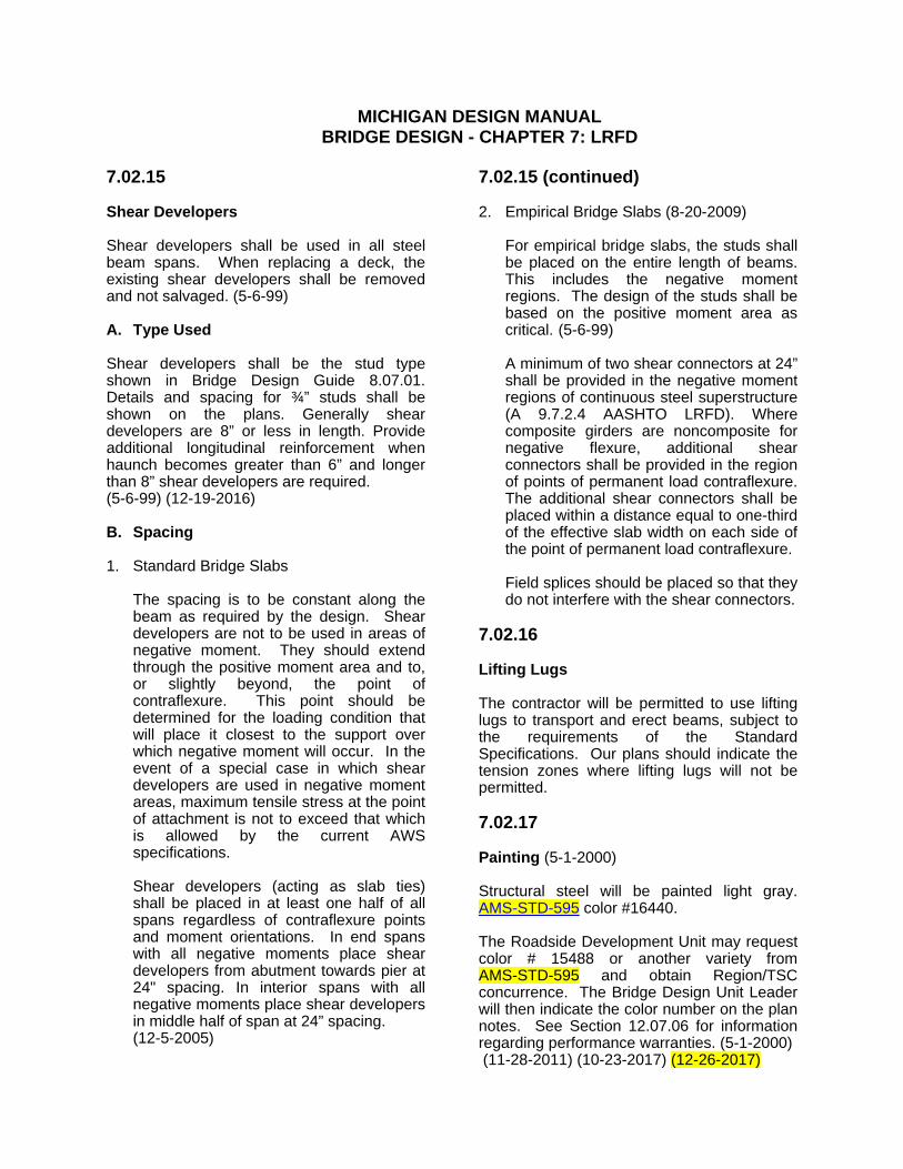
7.02.15 Shear Developers Shear developers shall be used in all steel beam spans. When replacing a deck, the existing shear developers shall be removed and not salvaged. (5-6-99) A. Type Used Shear developers shall be the stud type shown in Bridge Design Guide 8.07.01. Details and spacing for ¾” studs shall be shown on the plans. Generally shear developers are 8” or less in length. Provide additional longitudinal reinforcement when haunch becomes greater than 6” and longer than 8” shear developers are required. (5-6-99) (12-19-2016) B. Spacing 1. Standard Bridge Slabs The spacing is to be constant along the
beam as required by the design. Shear developers are not to be used in areas of negative moment. They should extend through the positive moment area and to, or slightly beyond, the point of contraflexure. This point should be determined for the loading condition that will place it closest to the support over which negative moment will occur. In the event of a special case in which shear developers are used in negative moment areas, maximum tensile stress at the point of attachment is not to exceed that which is allowed by the current AWS specifications.
Shear developers (acting as slab ties)
shall be placed in at least one half of all spans regardless of contraflexure points and moment orientations. In end spans with all negative moments place shear developers from abutment towards pier at 24" spacing. In interior spans with all negative moments place shear developers in middle half of span at 24” spacing.
(12-5-2005)
7.02.15 (continued) 2. Empirical Bridge Slabs For empirical bridge slabs, the studs shall
be placed on the entire length of beams. This includes the negative moment regions. The design of the studs shall be based on the positive moment area as critical. (5-6-99)
Studs shall be omitted from bolted splice
plates (see AASHTO Specs., Article 10.38.5.1.3).
7.02.16 Lifting Lugs The contractor will be permitted to use lifting lugs to transport and erect beams, subject to the requirements of the Standard Specifications. Our plans should indicate the tension zones where lifting lugs will not be permitted. 7.02.17 Painting (5-1-2000) Structural steel will be painted light gray. AMS-STD-595 color #16440. The Roadside Development Unit may request color # 15488 or another variety from AMS-STD-595 and obtain Region/TSC concurrence. The Bridge Design Unit Leader will then indicate the color number on the plan notes. See Section 12.07.06 for information regarding performance warranties. (5-1-2000) (11-28-2011) (10-23-2017) (12-26-2017)
MICHIGAN DESIGN MANUAL BRIDGE DESIGN - CHAPTER 7: LRFD
7.02.15 Shear Developers Shear developers shall be used in all steel beam spans. When replacing a deck, the existing shear developers shall be removed and not salvaged. (5-6-99) A. Type Used Shear developers shall be the stud type shown in Bridge Design Guide 8.07.01. Details and spacing for ¾” studs shall be shown on the plans. Generally shear developers are 8” or less in length. Provide additional longitudinal reinforcement when haunch becomes greater than 6” and longer than 8” shear developers are required. (5-6-99) (12-19-2016) B. Spacing 1. Standard Bridge Slabs The spacing is to be constant along the
beam as required by the design. Shear developers are not to be used in areas of negative moment. They should extend through the positive moment area and to, or slightly beyond, the point of contraflexure. This point should be determined for the loading condition that will place it closest to the support over which negative moment will occur. In the event of a special case in which shear developers are used in negative moment areas, maximum tensile stress at the point of attachment is not to exceed that which is allowed by the current AWS specifications.
Shear developers (acting as slab ties)
shall be placed in at least one half of all spans regardless of contraflexure points and moment orientations. In end spans with all negative moments place shear developers from abutment towards pier at 24" spacing. In interior spans with all negative moments place shear developers in middle half of span at 24” spacing.
(12-5-2005)
7.02.15 (continued) 2. Empirical Bridge Slabs (8-20-2009) For empirical bridge slabs, the studs shall
be placed on the entire length of beams. This includes the negative moment regions. The design of the studs shall be based on the positive moment area as critical. (5-6-99)
A minimum of two shear connectors at 24”
shall be provided in the negative moment regions of continuous steel superstructure (A 9.7.2.4 AASHTO LRFD). Where composite girders are noncomposite for negative flexure, additional shear connectors shall be provided in the region of points of permanent load contraflexure. The additional shear connectors shall be placed within a distance equal to one-third of the effective slab width on each side of the point of permanent load contraflexure.
Field splices should be placed so that they
do not interfere with the shear connectors. 7.02.16 Lifting Lugs The contractor will be permitted to use lifting lugs to transport and erect beams, subject to the requirements of the Standard Specifications. Our plans should indicate the tension zones where lifting lugs will not be permitted. 7.02.17 Painting (5-1-2000) Structural steel will be painted light gray. AMS-STD-595 color #16440. The Roadside Development Unit may request color # 15488 or another variety from AMS-STD-595 and obtain Region/TSC concurrence. The Bridge Design Unit Leader will then indicate the color number on the plan notes. See Section 12.07.06 for information regarding performance warranties. (5-1-2000) (11-28-2011) (10-23-2017) (12-26-2017)

MICHIGAN DESIGN MANUAL BRIDGE DESIGN
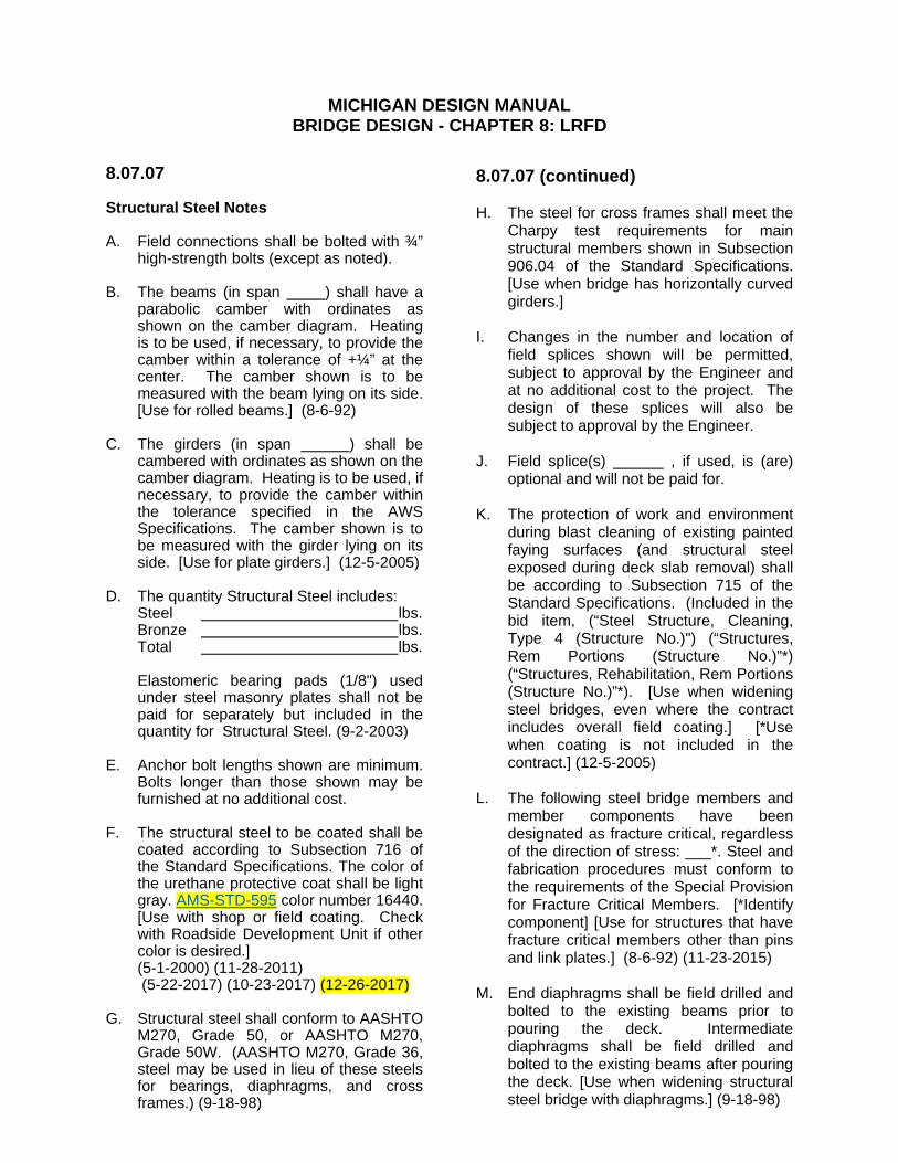
8.07.07 Structural Steel Notes
A. Field connections shall be bolted with ¾” high-strength bolts (except as noted).
B. The beams (in span ) shall have a
parabolic camber with ordinates as shown on the camber diagram. Heating is to be used, if necessary, to provide the camber within a tolerance of +¼” at the center. The camber shown is to be measured with the beam lying on its side. [Use for rolled beams.] (8-6-92)
C. The girders (in span ) shall be
cambered with ordinates as shown on the camber diagram. Heating is to be used, if necessary, to provide the camber within the tolerance specified in the AWS Specifications. The camber shown is to be measured with the girder lying on its side. [Use for plate girders.] (12-5-2005)
D. The quantity Structural Steel includes: Steel lbs. Bronze lbs. Total lbs.
Elastomeric bearing pads(1/8") used under steel masonry plates shall not be paid for separately but included in the quantity for Structural Steel. (9-2-2003)
E. Anchor bolt lengths shown are minimum.
Bolts longer than those shown may be furnished at no additional cost.
F. The structural steel to be coated shall be
coated according to Subsection 716 of the Standard Specifications. The color of the urethane protective coat shall be light gray. AMS-STD-595 color number 16440. [Use with shop or field coating. Check with Roadside Development Unit if other color is desired.]
(5-1-2000) (11-28-2011) (5-22-2017) (10-23-2017) (12-26-2017) G. Structural steel shall conform to AASHTO
M270, Grade 50, or AASHTO M270, Grade 50W. (AASHTO M270, Grade 36, steel may be used in lieu of these steels for bearings, diaphragms, and cross frames.) (9-18-98)
8.07.07 (continued) H. The steel for cross frames shall meet the
Charpy test requirements for main structural members shown in Subsection 906.04 of the Standard Specifications. [Use when bridge has horizontally curved girders.]
I. Changes in the number and location of
field splices shown will be permitted, subject to approval by the Engineer and at no additional cost to the project. The design of these splices will also be subject to approval by the Engineer.
J. Field splice(s) , if used, is (are)
optional and will not be paid for. K. The protection of work and environment
during blast cleaning of existing painted faying surfaces (and structural steel exposed during deck slab removal) shall be according to Subsection 715 of the Standard Specifications. (Included in the bid item, (“Steel Structure, Cleaning, Type 4 (Structure No.)") (“Structures, Rem Portions (Structure No.)”*) (“Structures, Rehabilitation, Rem Portions (Structure No.)”*). [Use when widening steel bridges, even where the contract includes overall field coating.] [*Use when coating is not included in the contract.] (12-5-2005)
L. The following steel bridge members and
member components have been designated as fracture critical, regardless of the direction of stress: ___*. Steel and fabrication procedures must conform to the requirements of the Special Provision for Fracture Critical Members. [*Identify component] [Use for structures that have fracture critical members other than pins and link plates.] (8-6-92) (11-23-2015)
M. End diaphragms shall be field drilled and
bolted to the existing beams prior to pouring the deck. Intermediate diaphragms shall be field drilled and bolted to the existing beams after pouring the deck. [Use when widening structural steel bridge with diaphragms.] (9-18-98)
MICHIGAN DESIGN MANUAL BRIDGE DESIGN - CHAPTER 8: LRFD
8.07.07 Structural Steel Notes
A. Field connections shall be bolted with ¾” high-strength bolts (except as noted).
B. The beams (in span ) shall have a
parabolic camber with ordinates as shown on the camber diagram. Heating is to be used, if necessary, to provide the camber within a tolerance of +¼” at the center. The camber shown is to be measured with the beam lying on its side. [Use for rolled beams.] (8-6-92)
C. The girders (in span ) shall be
cambered with ordinates as shown on the camber diagram. Heating is to be used, if necessary, to provide the camber within the tolerance specified in the AWS Specifications. The camber shown is to be measured with the girder lying on its side. [Use for plate girders.] (12-5-2005)
D. The quantity Structural Steel includes: Steel lbs. Bronze lbs. Total lbs.
Elastomeric bearing pads (1/8") used under steel masonry plates shall not be paid for separately but included in the quantity for Structural Steel. (9-2-2003)
E. Anchor bolt lengths shown are minimum.
Bolts longer than those shown may be furnished at no additional cost.
F. The structural steel to be coated shall be
coated according to Subsection 716 of the Standard Specifications. The color of the urethane protective coat shall be light gray. AMS-STD-595 color number 16440. [Use with shop or field coating. Check with Roadside Development Unit if other color is desired.]
(5-1-2000) (11-28-2011) (5-22-2017) (10-23-2017) (12-26-2017) G. Structural steel shall conform to AASHTO
M270, Grade 50, or AASHTO M270, Grade 50W. (AASHTO M270, Grade 36, steel may be used in lieu of these steels for bearings, diaphragms, and cross frames.) (9-18-98)
8.07.07 (continued) H. The steel for cross frames shall meet the
Charpy test requirements for main structural members shown in Subsection 906.04 of the Standard Specifications. [Use when bridge has horizontally curved girders.]
I. Changes in the number and location of
field splices shown will be permitted, subject to approval by the Engineer and at no additional cost to the project. The design of these splices will also be subject to approval by the Engineer.
J. Field splice(s) , if used, is (are)
optional and will not be paid for. K. The protection of work and environment
during blast cleaning of existing painted faying surfaces (and structural steel exposed during deck slab removal) shall be according to Subsection 715 of the Standard Specifications. (Included in the bid item, (“Steel Structure, Cleaning, Type 4 (Structure No.)") (“Structures, Rem Portions (Structure No.)”*) (“Structures, Rehabilitation, Rem Portions (Structure No.)”*). [Use when widening steel bridges, even where the contract includes overall field coating.] [*Use when coating is not included in the contract.] (12-5-2005)
L. The following steel bridge members and
member components have been designated as fracture critical, regardless of the direction of stress: ___*. Steel and fabrication procedures must conform to the requirements of the Special Provision for Fracture Critical Members. [*Identify component] [Use for structures that have fracture critical members other than pins and link plates.] (8-6-92) (11-23-2015)
M. End diaphragms shall be field drilled and
bolted to the existing beams prior to pouring the deck. Intermediate diaphragms shall be field drilled and bolted to the existing beams after pouring the deck. [Use when widening structural steel bridge with diaphragms.] (9-18-98)

MICHIGAN DESIGN MANUAL BRIDGE DESIGN
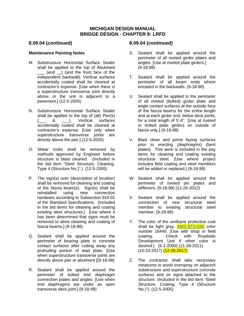
8.09.04 (continued) Maintenance Painting Notes M. Substructure Horizontal Surface Sealer
shall be applied to the top of Abutment ___ (and ) (and the front face of the independent backwall). Vertical surfaces accidentally coated shall be cleaned at contractor’s expense. [Use when there is a superstructure transverse joint directly above or the unit is adjacent to a pavement.] (12-5-2005)
N. Substructure Horizontal Surface Sealer
shall be applied to the top of (all) Pier(s) (___ & ___). Vertical surfaces accidentally coated shall be cleaned at contractor’s expense. [Use only when superstructure transverse joints are directly above the pier.] (12-5-2005)
O. Shear locks shall be removed by
methods approved by Engineer before structure is blast cleaned. (Included in the bid item “Steel Structure, Cleaning, Type 4 (Structure No.)".) (12-5-2005)
P. The sign(s) over (description of location)
shall be removed for cleaning and coating of the fascia beam(s). Sign(s) shall be reinstalled using new connection hardware according to Subsection 919.02 of the Standard Specifications. (Included in the bid items for cleaning and coating existing steel structures.) [Use where it has been determined that signs must be removed to allow cleaning and coating of fascia beams.] (9-18-98)
Q. Sealant shall be applied around the
perimeter of bearing plate to concrete contact surfaces after cutting away any protruding portion of lead plate. [Use when superstructure transverse joints are directly above pier or abutment.](9-18-98)
R. Sealant shall be applied around the
perimeter of bolted end diaphragm connection plates and angles. [Use when end diaphragms are under an open transverse deck joint.] (9-18-98)
8.09.04 (continued) S. Sealant shall be applied around the
perimeter of all riveted girder plates and angles. [Use at riveted plate girders.]
(9-18-98) T. Sealant shall be applied around the
perimeter of all beam ends where encased in the backwalls. (9-18-98)
U. Sealant shall be applied to the perimeter
of all riveted (bolted) girder plate and angle contact surfaces at the outside face of the fascia beams for the entire length and at each girder end, below deck joints, for a total length of 5'-0" [Use at riveted or bolted plate girders on outside of fascia only.] (9-18-98)
V. Blast clean and prime faying surfaces
prior to erecting (diaphragms) (bent plates). This work is included in the pay items for cleaning and coating existing structural steel. [Use where project includes field coating and steel members will be added or replaced.] (9-18-98)
W. Sealant shall be applied around the
perimeter of riveted pin plates and stiffeners. (9-18-98) (11-26-2012)
X. Sealant shall be applied around the
connection of new structural steel member to existing structural steel member. (9-18-98)
Y. The color of the urethane protective coat
shall be light gray. AMS-STD-595 color number 16440. [Use with shop or field coating. Check with Roadside Development Unit if other color is desired.] (5-1-2000) (11-28-2011)
(10-23-2017) (12-26-2017) Z. The contractor shall take necessary
measures to avoid overspray on adjacent substructure and superstructure concrete surfaces and on signs attached to the structure. (Included in the bid item “Steel Structure, Coating, Type 4 (Structure No.)"). (12-5-2005)
MICHIGAN DESIGN MANUAL BRIDGE DESIGN - CHAPTER 8: LRFD
8.09.04 (continued) Maintenance Painting Notes M. Substructure Horizontal Surface Sealer
shall be applied to the top of Abutment ___ (and ) (and the front face of the independent backwall). Vertical surfaces accidentally coated shall be cleaned at contractor’s expense. [Use when there is a superstructure transverse joint directly above or the unit is adjacent to a pavement.] (12-5-2005)
N. Substructure Horizontal Surface Sealer
shall be applied to the top of (all) Pier(s) (___ & ___). Vertical surfaces accidentally coated shall be cleaned at contractor’s expense. [Use only when superstructure transverse joints are directly above the pier.] (12-5-2005)
O. Shear locks shall be removed by
methods approved by Engineer before structure is blast cleaned. (Included in the bid item “Steel Structure, Cleaning, Type 4 (Structure No.)".) (12-5-2005)
P. The sign(s) over (description of location)
shall be removed for cleaning and coating of the fascia beam(s). Sign(s) shall be reinstalled using new connection hardware according to Subsection 919.02 of the Standard Specifications. (Included in the bid items for cleaning and coating existing steel structures.) [Use where it has been determined that signs must be removed to allow cleaning and coating of fascia beams.] (9-18-98)
Q. Sealant shall be applied around the
perimeter of bearing plate to concrete contact surfaces after cutting away any protruding portion of lead plate. [Use when superstructure transverse joints are directly above pier or abutment.](9-18-98)
R. Sealant shall be applied around the
perimeter of bolted end diaphragm connection plates and angles. [Use when end diaphragms are under an open transverse deck joint.] (9-18-98)
8.09.04 (continued) S. Sealant shall be applied around the
perimeter of all riveted girder plates and angles. [Use at riveted plate girders.]
(9-18-98) T. Sealant shall be applied around the
perimeter of all beam ends where encased in the backwalls. (9-18-98)
U. Sealant shall be applied to the perimeter
of all riveted (bolted) girder plate and angle contact surfaces at the outside face of the fascia beams for the entire length and at each girder end, below deck joints, for a total length of 5'-0" [Use at riveted or bolted plate girders on outside of fascia only.] (9-18-98)
V. Blast clean and prime faying surfaces
prior to erecting (diaphragms) (bent plates). This work is included in the pay items for cleaning and coating existing structural steel. [Use where project includes field coating and steel members will be added or replaced.] (9-18-98)
W. Sealant shall be applied around the
perimeter of riveted pin plates and stiffeners. (9-18-98) (11-26-2012)
X. Sealant shall be applied around the
connection of new structural steel member to existing structural steel member. (9-18-98)
Y. The color of the urethane protective coat
shall be light gray. AMS-STD-595 color number 16440. [Use with shop or field coating. Check with Roadside Development Unit if other color is desired.] (5-1-2000) (11-28-2011)
(10-23-2017) (12-26-2017) Z. The contractor shall take necessary
measures to avoid overspray on adjacent substructure and superstructure concrete surfaces and on signs attached to the structure. (Included in the bid item “Steel Structure, Coating, Type 4 (Structure No.)"). (12-5-2005)
MICHIGAN DESIGN MANUAL BRIDGE DESIGN
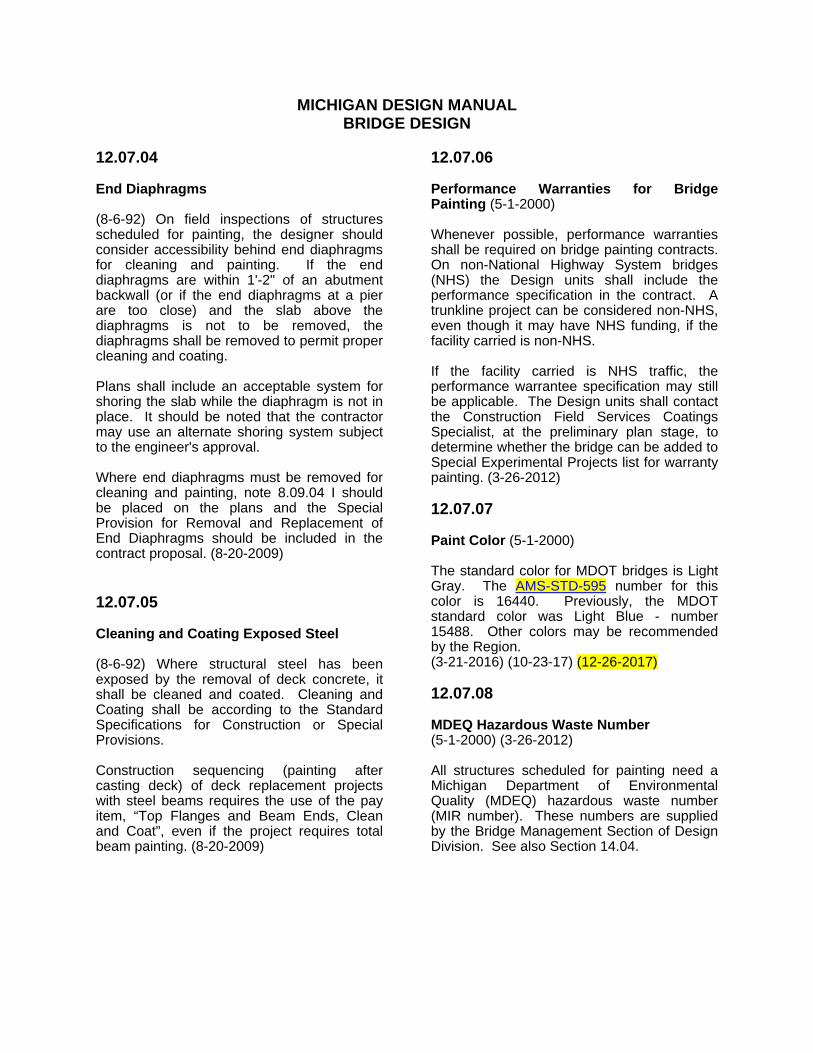
12.07.04 End Diaphragms (8-6-92) On field inspections of structures scheduled for painting, the designer should consider accessibility behind end diaphragms for cleaning and painting. If the end diaphragms are within 1'-2" of an abutment backwall (or if the end diaphragms at a pier are too close) and the slab above the diaphragms is not to be removed, the diaphragms shall be removed to permit proper cleaning and coating. Plans shall include an acceptable system for shoring the slab while the diaphragm is not in place. It should be noted that the contractor may use an alternate shoring system subject to the engineer's approval. Where end diaphragms must be removed for cleaning and painting, note 8.09.04 I should be placed on the plans and the Special Provision for Removal and Replacement of End Diaphragms should be included in the contract proposal. (8-20-2009) 12.07.05 Cleaning and Coating Exposed Steel (8-6-92) Where structural steel has been exposed by the removal of deck concrete, it shall be cleaned and coated. Cleaning and Coating shall be according to the Standard Specifications for Construction or Special Provisions. Construction sequencing (painting after casting deck) of deck replacement projects with steel beams requires the use of the pay item, “Top Flanges and Beam Ends, Clean and Coat”, even if the project requires total beam painting. (8-20-2009)
12.07.06 Performance Warranties for Bridge Painting (5-1-2000) Whenever possible, performance warranties shall be required on bridge painting contracts. On non-National Highway System bridges (NHS) the Design units shall include the performance specification in the contract. A trunkline project can be considered non-NHS, even though it may have NHS funding, if the facility carried is non-NHS. If the facility carried is NHS traffic, the performance warrantee specification may still be applicable. The Design units shall contact the Construction Field Services Coatings Specialist, at the preliminary plan stage, to determine whether the bridge can be added to Special Experimental Projects list for warranty painting. (3-26-2012) 12.07.07 Paint Color (5-1-2000) The standard color for MDOT bridges is Light Gray. The AMS-STD-595 number for this color is 16440. Previously, the MDOT standard color was Light Blue - number 15488. Other colors may be recommended by the Region. (3-21-2016) (10-23-17) (12-26-2017) 12.07.08 MDEQ Hazardous Waste Number (5-1-2000) (3-26-2012) All structures scheduled for painting need a Michigan Department of Environmental Quality (MDEQ) hazardous waste number (MIR number). These numbers are supplied by the Bridge Management Section of Design Division. See also Section 14.04.
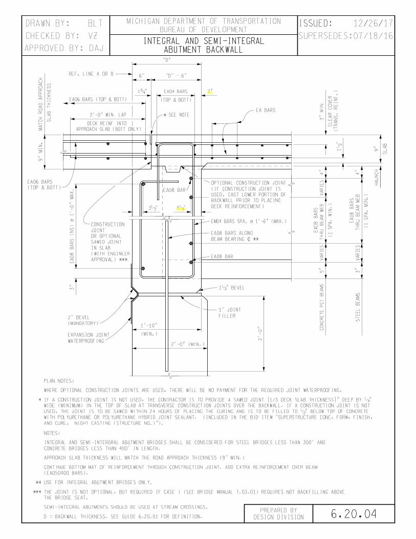
6.20.04
VZ
BLT
ISSUED: / /
ABUTMENT BACKWALLINTEGRAL AND SEMI-INTEGRAL
THE BRIDGE SEAT.
*** THE JOINT IS NOT OPTIONAL, BUT REQUIRED IF CASE I (SEE BRIDGE MANUAL 7.03.01) REQUIRES NOT BACKFILLING ABOVE
D = BACKWALL THICKNESS. SEE GUIDE 6.20.01 FOR DEFINITION.
** USE FOR INTEGRAL ABUTMENT BRIDGES ONLY.
(EA050400 BARS).
CONTINUE BOTTOM MAT OF REINFORCEMENT THROUGH CONSTRUCTION JOINT. ADD EXTRA REINFORCEMENT OVER BEAM
CONCRETE BRIDGES LESS THAN 400' IN LENGTH.
INTEGRAL AND SEMI-INTERGRAL ABUTMENT BRIDGES SHALL BE CONSIDERED FOR STEEL BRIDGES LESS THAN 300' AND
NOTES:
WHERE OPTIONAL CONSTRUCTION JOINTS ARE USED, THERE WILL BE NO PAYMENT FOR THE REQUIRED JOINT WATERPROOFING.
PLAN NOTES:S
LA
B
HA
UN
CH
"D"
(T
RA
NS.
REI
NF.)
CL
EA
R
CO
VE
R
DECK REINFORCEMENT)
BACKWALL PRIOR TO PLACING
USED, CAST LOWER PORTION OF
(IF CONSTRUCTION JOINT IS
OPTIONAL CONSTRUCTION JOINT
EA04 BARS
(TOP & BOTT)EA06 BARS (TOP & BOTT)
APPROACH SLAB (BOTT ONLY)
DECK REINF INTO
REF. LINE A OR B
SL
AB
THI
CK
NE
SS
MA
TC
H
RO
AD
AP
PR
OA
CH
WATERPROOFING
EXPANSION JOINT
BEAM BEARING \ **
EA08 BARS ALONG
(MIN.)
EA BARS
VA
RI
ES
EA08 BAR
EA08 BAR
VA
RI
ES
(1
SP
A.
MI
N.)
TH
RU
BE
AM
WE
B
EA08
BA
RS
(1
SP
A.
MI
N.)
TH
RU
BE
AM
WE
B
EA08
BA
RS
VA
RI
ES
CO
NC
RE
TE
PCI
BE
AM
S
ST
EE
L
BE
AM
S
(TOP & BOTT)
EA06 BARS
6" "D" - 6"
1ƒ"
2'-0" MIN. LAP
9"
MI
N.
EA08
BA
RS (
NS)
@ 1'-0"
MA
X.
3•" 3‚"
EM04 BARS SPA. @ 1'-6" (MAX.)
4"
4"
9"
1•
"
3"
5"
FILLER
1" JOINT
1•" BEVEL
1'-10"
2'-0" (MIN.)
(MANDATORY)
2" BEVEL
3"
2'-0"
APPROACH SLAB THICKNESS WILL MATCH THE ROAD APPROACH THICKNESS (9" MIN.)
3"
MI
N.
* SEE NOTE
SEMI-INTEGRAL ABUTMENTS SHOULD BE USED AT STREAM CROSSINGS.
APPROVAL) ***
(WITH ENGINEER
IN SLAB
SAWED JOINT
OR OPTIONAL
JOINT
CONSTRUCTION
SUPERSEDES:07/18/16
AND CURE, NIGHT CASTING (STRUCTURE NO.)").
WITH POLYURETHANE OR POLYURETHANE HYBRID JOINT SEALANT. (INCLUDED IN THE BID ITEM "SUPERSTRUCTURE CONC, FORM, FINISH,
USED, THE JOINT IS TO BE SAWED WITHIN 24 HOURS OF PLACING THE CURING AND IS TO BE FILLED TO •" BELOW TOP OF CONCRETE
WIDE (MINIMUM) IN THE TOP OF SLAB AT TRANSVERSE CONSTRUCTION JOINTS OVER THE BACKWALL. IF A CONSTRUCTION JOINT IS NOT
* IF A CONSTRUCTION JOINT IS NOT USED, THE CONTRACTOR IS TO PROVIDE A SAWED JOINT [1/3 DECK SLAB THICKNESS]" DEEP BY ‚"
BUREAU OF DEVELOPMENT
MICHIGAN DEPARTMENT OF TRANSPORTATIONDRAWN BY:
APPROVED BY: DAJ
DESIGN DIVISION
PREPARED BY
ISSUED: 12/26/17
CHECKED BY:
2"
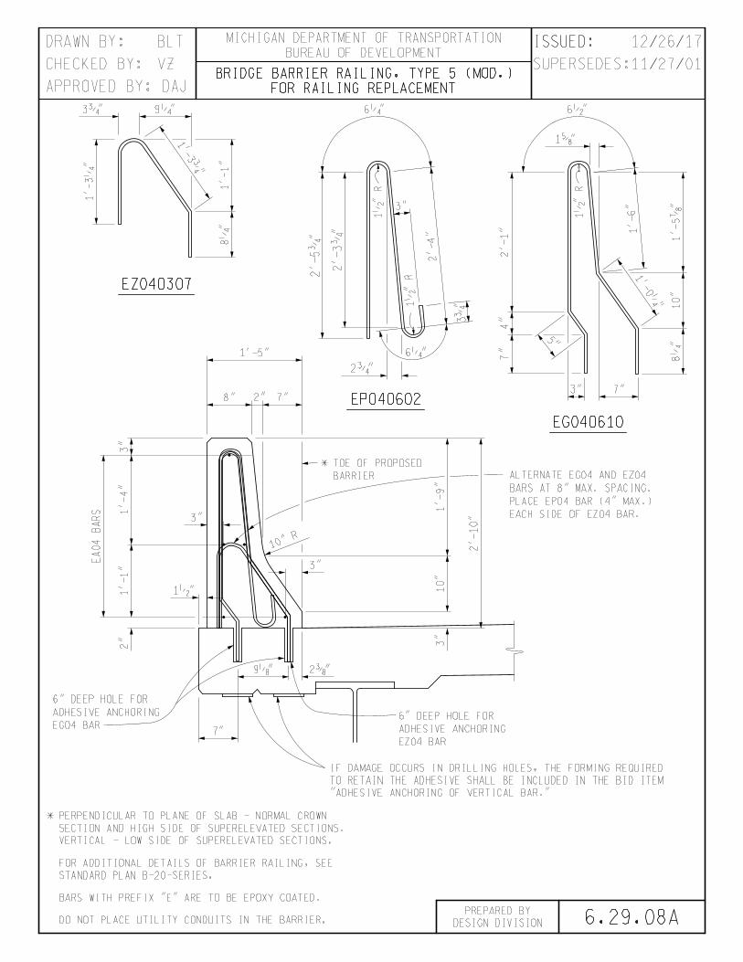
6.29.08A
VZ
BLT ISSUED: / /
BARS WITH PREFIX "E" ARE TO BE EPOXY COATED.
11/27/01
EP040602
FOR RAILING REPLACEMENT
BRIDGE BARRIER RAILING, TYPE 5 (MOD.)
EZ040307
EA04
BA
RS
DO NOT PLACE UTILITY CONDUITS IN THE BARRIER.
STANDARD PLAN B-20-SERIES.
FOR ADDITIONAL DETAILS OF BARRIER RAILING, SEE
VERTICAL - LOW SIDE OF SUPERELEVATED SECTIONS.
SECTION AND HIGH SIDE OF SUPERELEVATED SECTIONS.
* PERPENDICULAR TO PLANE OF SLAB - NORMAL CROWN
BARRIER
* TOE OF PROPOSED
"ADHESIVE ANCHORING OF VERTICAL BAR."
TO RETAIN THE ADHESIVE SHALL BE INCLUDED IN THE BID ITEM
IF DAMAGE OCCURS IN DRILLING HOLES, THE FORMING REQUIRED
EG040610
3ƒ" 9‚"
1'-
3‚
"
1'-3ƒ"
1'-
1"
8‚
"
1•
"
R
6‚"
3"
2'-
5ƒ
"
2'-
3ƒ
"
3ƒ"
2'-4"
1•"
R
6‚"
2ƒ"
1'-6"
1•
"
R
10"
1'-0‚"
1'-
5‡
"8‚
"
7"3"
4"
7"
2'-
1"
1†"
6•"
5"
8" 7"2"
1'-5"
3"
1'-4"
3"
1•"1'-1"
2"
EG04 BAR
ADHESIVE ANCHORING
6" DEEP HOLE FOR
7"
EZ04 BAR
ADHESIVE ANCHORING
6" DEEP HOLE FOR
2…"
EACH SIDE OF EZ04 BAR.
PLACE EP04 BAR (4" MAX.)
BARS AT 8" MAX. SPACING.
ALTERNATE EG04 AND EZ04
10"
R
1'-9"
2'-10"
10"
3"
3"
9„"
BUREAU OF DEVELOPMENT
MICHIGAN DEPARTMENT OF TRANSPORTATIONDRAWN BY:
APPROVED BY: DAJ
CHECKED BY:
DESIGN DIVISION
PREPARED BY
SUPERSEDES: / /
ISSUED: 12/26/17
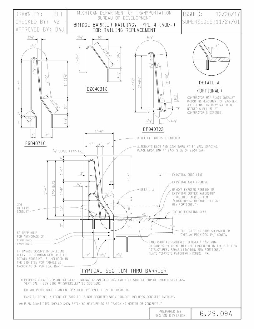
6.29.09A
VZ
BLT
ISSUED: / /
11/27/01
FOR RAILING REPLACEMENT
BRIDGE BARRIER RAILING, TYPE 4 (MOD.)
EZ040310
EA04
BA
RS
TOP OF EXISTING SLAB
REM PORTIONS.")
"STRUCTURES, REHABILITATION,
(INCLUDED IN BID ITEM
EXISTING COPPER WATERSTOP
REMOVE EXPOSED PORTION OF
EXISTING WALK (REMOVE)
EXISTING CURB LINE
* TOE OF PROPOSED BARRIER
DETAIL A
EP040702
DETAIL A
(OPTIONAL)
CONTRACTOR'S EXPENSE.
NEEDED SHALL BE AT
ADDITIONAL OVERLAY MATERIAL
PRIOR TO PLACEMENT OF BARRIER.
CONTRACTOR MAY PLACE OVERLAY
EG040710
ANCHORING OF VERTICAL BAR."
THE BID ITEM FOR "ADHESIVE
RETAIN ADHESIVE IS INCLUDED IN
HOLE, THE FORMING REQUIRED TO
IF DAMAGE OCCURS IN DRILLING
HAND CHIPPING IN FRONT OF BARRIER IS NOT REQUIRED WHEN PROJECT INCLUDES CONCRETE OVERLAY.
** PLAN QUANTITIES SHOULD SHOW PATCHING MIXTURE TO BE "PATCHING MORTAR OR CONCRETE."
VERTICAL - LOW SIDE OF SUPERELEVATED SECTIONS.
* PERPENDICULAR TO PLANE OF SLAB - NORMAL CROWN SECTIONS AND HIGH SIDE OF SUPERELEVATED SECTIONS.
TYPICAL SECTION THRU BARRIER
4%
1"
1'-0‚"
8‚
"10"
1'-11‡
"
2'-0"
6•"
2†"
1•
"
R
2'-7"
7"3"
4"
7"
5"
6‚"10"
8‚
"1'-2‚
"
1'-5•"
3ƒ"
1'-4•
"
1•
"
R
1•"
R
3ƒ"
6‚"3ƒ"
2'-11ƒ
"
2'-9ƒ
"
2'-10"
3"
7" 2…"
EZ04 BARS
EG04 BARS
FOR ANCHORAGE OF:
6" DEEP HOLE
3"
10"
10"
R
1'-6"
8" 7"3"
3"
ƒ" BEVEL (TYP.)
1'-1"
1'-0"
10"
3'-4"
CONDUIT
UTILITY
3"!
2"
3"
1•"
2'-3"
3"
PLACE EP04 BAR 4" EACH SIDE OF EZ04 BAR.
ALTERNATE EG04 AND EZ04 BARS AT 8" MAX. SPACING.
OVERLAY PROVIDES 1•" COVER.
CUT EXISTING BARS SO PATCH OR
PLACE CONCRETE PATCHING MIXTURE. **
"STRUCTURES, REHABILITATION, REM PORTIONS.")
THICKNESS PATCHING MIXTURE (INCLUDED IN THE BID ITEM
HAND CHIP AS REQUIRED TO OBTAIN 1•" MIN.
10„"
DO NOT PLACE MORE THAN ONE 3"! UTILITY CONDUIT IN THE BARRIER.
BUREAU OF DEVELOPMENT
MICHIGAN DEPARTMENT OF TRANSPORTATIONDRAWN BY:
APPROVED BY: DAJ
CHECKED BY:
DESIGN DIVISION
PREPARED BY
SUPERSEDES: / /
ISSUED: 12/26/17

8.21.03
VZ
BLT
ISSUED: / /
"D"
PILE DIAMETER
"D"
PILE DIAMETER
"D"/2 "D"/2
\ PILE \ PILE
TYP.
3•
"ƒ
"*
ƒ"
*
…"
…"
"D" + ƒ"
"D" + ƒ"
ƒ"
*
TY
P.
Š"***
Š"**
‚"*
*** --- 16" PILE
** --- 14" PILE
* --- 12" PILE
Š"***
Š"**
‚"*
1‚
"***
1"
**
1‚
"***
1"
**
1‚
"*
**
TY
P.
1"
**
TY
P.
CIP PILE POINT/END PLATE DETAILS
END PLATEEND PLATE
CIP PILE POINT DETAILS
RECOMMENDED BY GEOTECHNICAL SERVICES SECTION.
FOR POINT BEARING PILES ONLY. USE WHEN
CIP PILE END PLATE DETAILS
THE END PLATES DETAILED ON THIS SHEET SHOULD NOT BE PAID FOR SEPARATELY.
NOTE TO DESIGNER:
POINT
PILE
BUREAU OF DEVELOPMENT
MICHIGAN DEPARTMENT OF TRANSPORTATIONDRAWN BY:
APPROVED BY: DAJ
CHECKED BY:
DESIGN DIVISION
PREPARED BY
SUPERSEDES:10/17/16
ISSUED: 12/26/17


