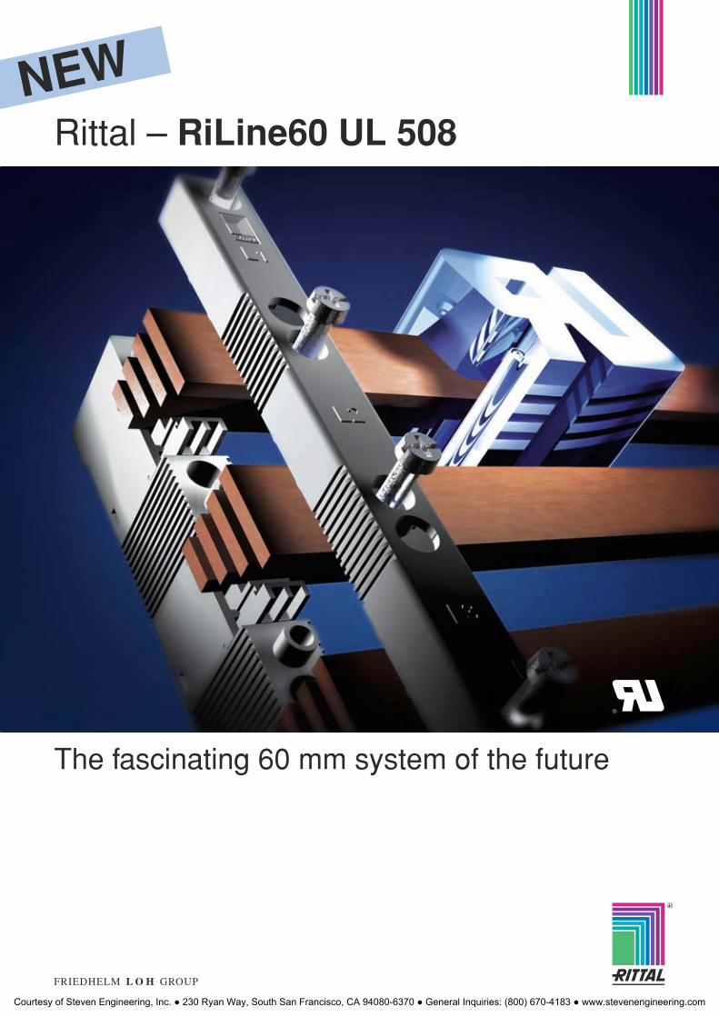
Rittal – RiLine60 UL 508
The fascinating 60 mm system of the future
NEW
R
Courtesy of Steven Engineering, Inc. ● 230 Ryan Way, South San Francisco, CA 94080-6370 ● General Inquiries: (800) 670-4183 ● www.stevenengineering.com
2 Rittal RiLine60 UL
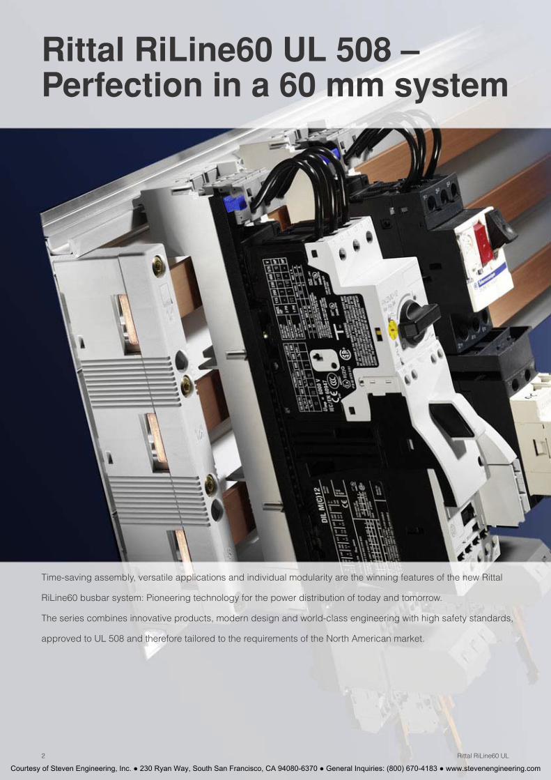
Rittal RiLine60 UL 508 – Perfection in a 60 mm system
Time-saving assembly, versatile applications and individual modularity are the winning features of the new Rittal
RiLine60 busbar system: Pioneering technology for the power distribution of today and tomorrow.
The series combines innovative products, modern design and world-class engineering with high safety standards,
approved to UL 508 and therefore tailored to the requirements of the North American market.
Courtesy of Steven Engineering, Inc. ● 230 Ryan Way, South San Francisco, CA 94080-6370 ● General Inquiries: (800) 670-4183 ● www.stevenengineering.com

3Rittal RiLine60 UL
Rittal RiLine60 busbar systems from page 4Flat bar systems – Busbar supports/system components ....................................................................... 8/9Rittal PLS busbar systems – PLS busbar supports/system components ............................................................ 10/11
Connection systems from page 12Busbar connection adaptors .................................................................................... 12/13
Component adaptors from page 14OM adaptors– 25 A/32 A/40 A with connection cables .......................................................................14– 65 A with connection cables....................................................................................... 15OT adaptors– 25 A/32 A with connection cables................................................................................16– 65 A with connection cables....................................................................................... 17OM supports (without contact system) ...........................................................................18OT supports (without contact system) ............................................................................19Component adaptors 100 A........................................................................................... 20Circuit-breaker component adaptors 125 A/250 A/600 A ........................................ 20/21
Technical details from page 22Short-circuit resistance .................................................................................................. 22
List of Model Numbers................................................................................................... 23Index .............................................................................................................................. 23
Important notes for the use of busbar systems to UL 508/508AOne key difference from the IEC provisions on busbar systems concerns the creepage distances and clearances required by UL for use in feeder circuits. The following distances are required:
● Between phases:
− Creepage distance 50.8 mm (2 inches)
− Clearance 25.4 mm (1 inch)
● Between phase and earthed, uninsulated metal parts:
− Creepage distance and clearance 25.4 mm (1 inch)
All the Rittal RiLine60 components in this brochure comply with these requirements.
Please note two further points compared with the IEC version:
● The Rittal RiLine60 UL busbar supports for flat bars and Rittal PLS have increased creepage distances and clearances between phases.
● In order to guarantee the required distances between live parts and the earthed mounting plate, the use of a Rittal RiLine60 base tray is compulsory.
Further details of UL 508 may be found on page 6/7.
Courtesy of Steven Engineering, Inc. ● 230 Ryan Way, South San Francisco, CA 94080-6370 ● General Inquiries: (800) 670-4183 ● www.stevenengineering.com
Rittal RiLine60 UL
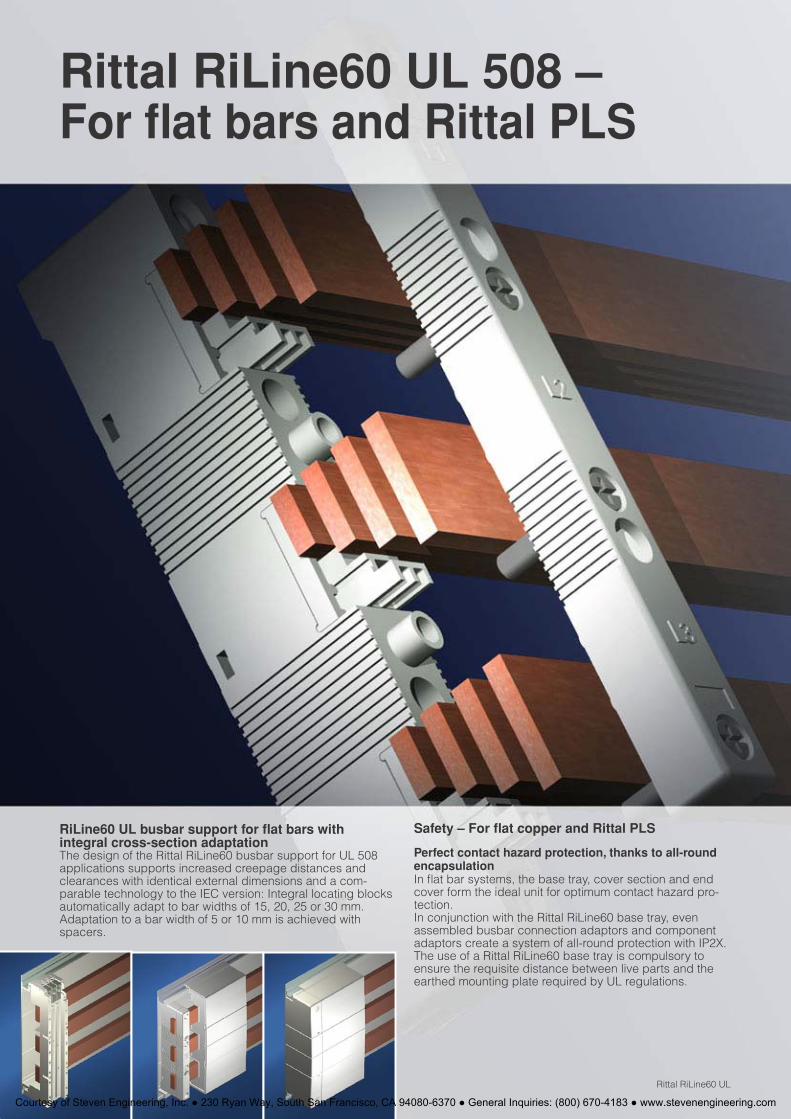
Rittal RiLine60 UL 508 – For flat bars and Rittal PLS
RiLine60 UL busbar support for flat bars with integral cross-section adaptation The design of the Rittal RiLine60 busbar support for UL 508 applications supports increased creepage distances and clearances with identical external dimensions and a com-parable technology to the IEC version: Integral locating blocks automatically adapt to bar widths of 15, 20, 25 or 30 mm. Adaptation to a bar width of 5 or 10 mm is achieved with spacers.
Safety – For flat copper and Rittal PLS
Perfect contact hazard protection, thanks to all-round encapsulationIn flat bar systems, the base tray, cover section and end cover form the ideal unit for optimum contact hazard pro-tection.In conjunction with the Rittal RiLine60 base tray, even assembled busbar connection adaptors and component adaptors create a system of all-round protection with IP2X. The use of a Rittal RiLine60 base tray is compulsory to ensure the requisite distance between live parts and the earthed mounting plate required by UL regulations.
Courtesy of Steven Engineering, Inc. ● 230 Ryan Way, South San Francisco, CA 94080-6370 ● General Inquiries: (800) 670-4183 ● www.stevenengineering.com
Rittal RiLine60 UL
Products which conform to the relevant regulations are a key factor for problem-free acceptance of electrical
systems in North America. UL-approved components provide a suitable basis, saving time and money for the
user by minimising acceptance problems in advance. This brochure summarises all the Rittal RiLine60 products
which are suitable for use in feeder circuits to UL 508A.
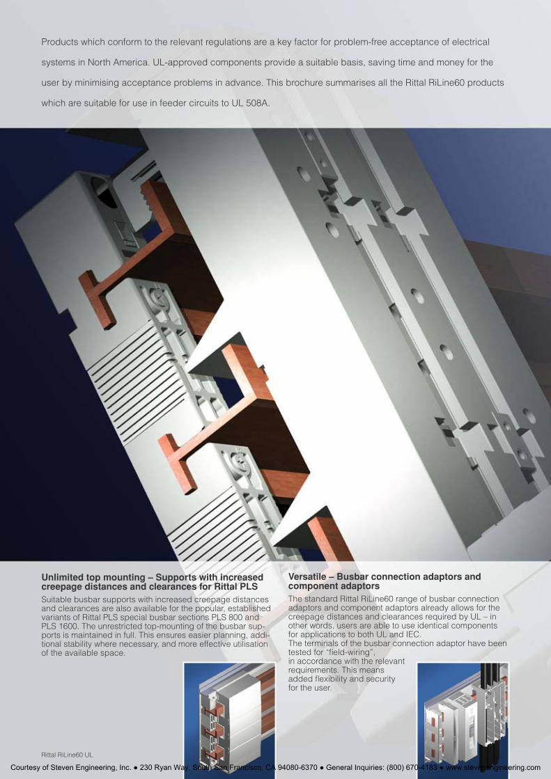
Unlimited top mounting – Supports with increased creepage distances and clearances for Rittal PLS Suitable busbar supports with increased creepage distances and clearances are also available for the popular, established variants of Rittal PLS special busbar sections PLS 800 and PLS 1600. The unrestricted top-mounting of the busbar sup-ports is maintained in full. This ensures easier planning, addi-tional stability where necessary, and more effective utilisation of the available space.
Versatile – Busbar connection adaptors and component adaptors The standard Rittal RiLine60 range of busbar connection adaptors and component adaptors already allows for the creepage distances and clearances required by UL – in other words, users are able to use identical components for applications to both UL and IEC. The terminals of the busbar connection adaptor have been tested for “field-wiring”, in accordance with the relevant requirements. This means added flexibility and security for the user.
Courtesy of Steven Engineering, Inc. ● 230 Ryan Way, South San Francisco, CA 94080-6370 ● General Inquiries: (800) 670-4183 ● www.stevenengineering.com
Busbar systems UL 508Background information
6 Rittal RiLine60 UL
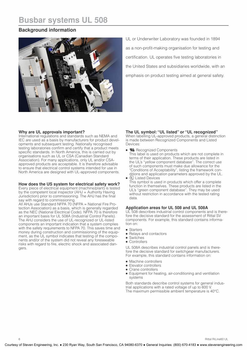
UL or Underwriter Laboratory was founded in 1894
as a non-profit-making organisation for testing and
certification. UL operates five testing laboratories in
the United States and subsidiaries worldwide, with an
emphasis on product testing aimed at general safety.
Why are UL approvals important? International regulations and standards such as NEMA and IEC are used as a basis by manufacturers for product devel-opments and subsequent testing. Nationally recognised testing laboratories confirm and certify that a product meets specific standards. In North America, this is carried out by organisations such as UL or CSA (Canadian Standard Association). For many applications, only UL and/or CSA-approved products are acceptable. It is therefore advisable to ensure that electrical control systems intended for use in North America are designed with UL-approved components.
How does the US system for electrical safety work? Every piece of electrical equipment (machine/plant) is tested by the competent local inspector (AHJ = Authority Having Jurisdiction) prior to commissioning. The AHJ has the final say with regard to commissioning. All AHJs use Standard NFPA 70 (NFPA = National Fire Pro-tection Association) as a basis, which is generally regarded as the NEC (National Electrical Code). NFPA 70 is therefore an important basis for UL 508A (Industrial Control Panels). The AHJ considers the use of UL-recognized or UL-listed components an important indication that a system complies with the safety requirements to NFPA 70. This saves time and money during construction and commissioning of the equip-ment, as the UL symbol indicates that testing of the compo-nents and/or of the system did not reveal any foreseeable risks with regard to fire, electric shock and associated dan-gers.
The UL symbol: “UL listed” or “UL recognized” When labelling UL-approved products, a general distinction is made between Recognized Components and Listed Devices:
● Recognized ComponentsThis label is used on products which are not complete in terms of their application. These products are listed in the UL’s “yellow component database”. The correct use of such components must make due allowance for the “Conditions of Acceptability”, listing the framework con-ditions and application parameters approved by the UL.
● Listed Devices This symbol is used in products which offer a complete function in themselves. These products are listed in the UL’s “green component database”. They may be used without restriction in accordance with the tested rating data.
Application areas for UL 508 and UL 508AUL 508 describes industrial control components and is there-fore the decisive standard for the assessment of Rittal SV components. For example, this standard contains informa-tion on:
● Starters
● Relays and contactors
● Switches
● Controllers
UL 508A describes industrial control panels and is there-fore the decisive standard for switchgear manufacturers. For example, this standard contains information on:
● Machine controllers
● Elevator controllers
● Crane controllers
● Equipment for heating, air-conditioning and ventilation systems
Both standards describe control systems for general indus-trial applications with a rated voltage of up to 600 V. The maximum permissible ambient temperature is 40°C.
Courtesy of Steven Engineering, Inc. ● 230 Ryan Way, South San Francisco, CA 94080-6370 ● General Inquiries: (800) 670-4183 ● www.stevenengineering.com
Background information
Busbar systems UL 508
7Rittal RiLine60 UL
Distinguishing between feeder and branch circuits Standard UL 508A makes a distinction between feeder cir-cuits and branch & control circuits. Generally speaking, the term “feeder circuits” refers to the part of the circuit located at the supply end before the last over-current protective device. Increased requirements with regard to creepage distances and clearances apply to this part of the circuit. The term “branch & control circuits” refers to the part of the circuit located after the last over-current protective device. When using busbar systems, it is important to know whether the application is in the feeder section or the branch section, as the requirements governing the required creepage dis-tances and clearances are significantly higher for feeder circuits.
Important notes for the use of busbar systems to UL 508/508A1. Creepage distances and clearancesOne of the principal changes in UL 508A is the amendment to the required creepage distances and clearances for feeder circuits. The following distances are required for appli-cations >250 V:
Between phases:
● Creepage distance 50.8 mm (2 inches)
● Clearance 25.4 mm (1 inch)
Between phase and earthed, uninsulated metal parts:
● Creepage distance 25.4 mm (1 inch)
● Clearance 25.4 mm (1 inch)
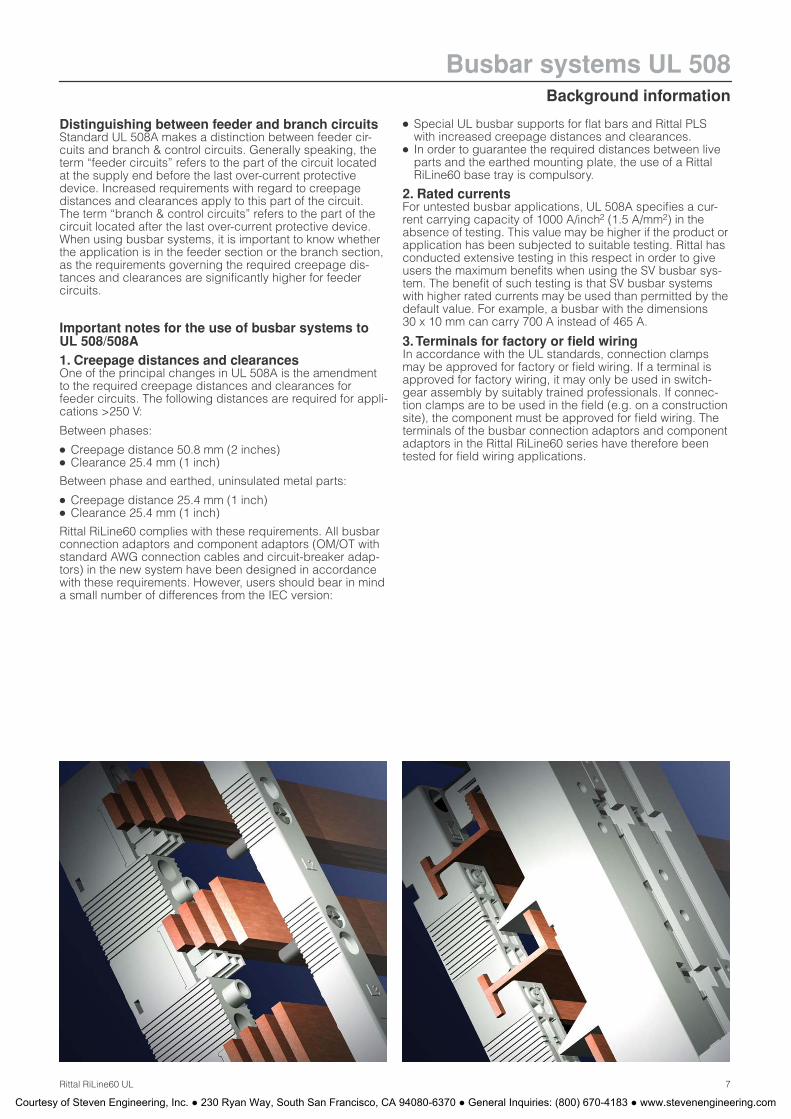
Rittal RiLine60 complies with these requirements. All busbar connection adaptors and component adaptors (OM/OT with standard AWG connection cables and circuit-breaker adap-tors) in the new system have been designed in accordance with these requirements. However, users should bear in mind a small number of differences from the IEC version:
● Special UL busbar supports for flat bars and Rittal PLS with increased creepage distances and clearances.
● In order to guarantee the required distances between live parts and the earthed mounting plate, the use of a Rittal RiLine60 base tray is compulsory.
2. Rated currentsFor untested busbar applications, UL 508A specifies a cur-rent carrying capacity of 1000 A/inch2 (1.5 A/mm2) in the absence of testing. This value may be higher if the product or application has been subjected to suitable testing. Rittal has conducted extensive testing in this respect in order to give users the maximum benefits when using the SV busbar sys-tem. The benefit of such testing is that SV busbar systems with higher rated currents may be used than permitted by the default value. For example, a busbar with the dimensions 30 x 10 mm can carry 700 A instead of 465 A.
3. Terminals for factory or field wiring In accordance with the UL standards, connection clamps may be approved for factory or field wiring. If a terminal is approved for factory wiring, it may only be used in switch-gear assembly by suitably trained professionals. If connec-tion clamps are to be used in the field (e.g. on a construction site), the component must be approved for field wiring. The terminals of the busbar connection adaptors and component adaptors in the Rittal RiLine60 series have therefore been tested for field wiring applications.
Courtesy of Steven Engineering, Inc. ● 230 Ryan Way, South San Francisco, CA 94080-6370 ● General Inquiries: (800) 670-4183 ● www.stevenengineering.com
Rittal RiLine60 busbar systems UL 508Busbar supports for feeder circuits
8 Rittal RiLine60 UL
12
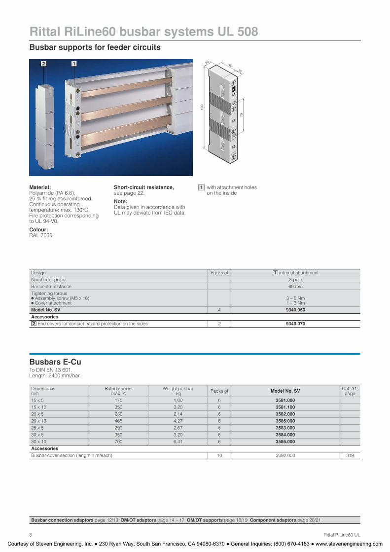
Material:Polyamide (PA 6.6), 25 % fibreglass-reinforced. Continuous operating temperature: max. 130°C. Fire protection corresponding to UL 94-V0.
Colour:RAL 7035
Short-circuit resistance,see page 22.
Note:Data given in accordance with UL may deviate from IEC data.
Design Packs of internal attachment
Number of poles 3-pole
Bar centre distance 60 mm
Tightening torque
● Assembly screw (M5 x 16)
● Cover attachment3 – 5 Nm 1 – 3 Nm
Model No. SV 4 9340.050
Accessories
End covers for contact hazard protection on the sides 2 9340.070
1
2
Busbars E-CuTo DIN EN 13 601. Length: 2400 mm/bar.
Dimensionsmm
Rated currentmax. A
Weight per bar kg Packs of Model No. SV Cat. 31,
page
15 x 5 175 1,60 6 3581.000
15 x 10 350 3,20 6 3581.100
20 x 5 230 2,14 6 3582.000
20 x 10 465 4,27 6 3585.000
25 x 5 290 2,67 6 3583.000
30 x 5 350 3,20 6 3584.000
30 x 10 700 6,41 6 3586.000
Accessories
Busbar cover section (length 1 m/each) 10 3092.000 319
Busbar connection adaptors page 12/13 OM/OT adaptors page 14 – 17 OM/OT supports page 18/19 Component adaptors page 20/21
with attachment holes on the inside
1
Courtesy of Steven Engineering, Inc. ● 230 Ryan Way, South San Francisco, CA 94080-6370 ● General Inquiries: (800) 670-4183 ● www.stevenengineering.com
System components for feeder circuits
Rittal RiLine60 busbar systems UL 508
9Rittal RiLine60 UL
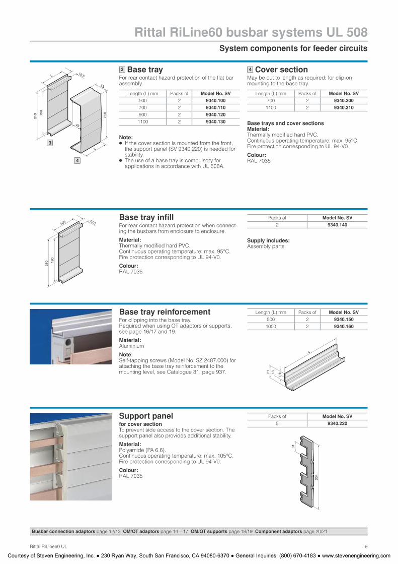
Base trayFor rear contact hazard protection of the flat bar assembly.
Note: ● If the cover section is mounted from the front,
the support panel (SV 9340.220) is needed for stability.
● The use of a base tray is compulsory for applications in accordance with UL 508A.
Cover sectionMay be cut to length as required; for clip-on mounting to the base tray.
Base trays and cover sectionsMaterial:Thermally modified hard PVC. Continuous operating temperature: max. 95°C. Fire protection corresponding to UL 94-V0.
Colour:RAL 7035
Length (L) mm Packs of Model No. SV
500 2 9340.100
700 2 9340.110
900 2 9340.120
1100 2 9340.130
3
Length (L) mm Packs of Model No. SV
700 2 9340.200
1100 2 9340.210
4
3
4
Base tray infill For rear contact hazard protection when connect-ing the busbars from enclosure to enclosure.
Material:Thermally modified hard PVC. Continuous operating temperature: max. 95°C. Fire protection corresponding to UL 94-V0.
Colour:RAL 7035
Supply includes:Assembly parts.
Packs of Model No. SV
2 9340.140
Base tray reinforcement For clipping into the base tray. Required when using OT adaptors or supports,see page 16/17 and 19.
Material:Aluminium
Note:Self-tapping screws (Model No. SZ 2487.000) for attaching the base tray reinforcement to the mounting level, see Catalogue 31, page 937.
Length (L) mm Packs of Model No. SV
500 2 9340.150
1000 2 9340.160
Support panel for cover section To prevent side access to the cover section. The support panel also provides additional stability.
Material:Polyamide (PA 6.6). Continuous operating temperature: max. 105°C. Fire protection corresponding to UL 94-V0.
Colour:RAL 7035
Packs of Model No. SV
5 9340.220
Busbar connection adaptors page 12/13 OM/OT adaptors page 14 – 17 OM/OT supports page 18/19 Component adaptors page 20/21
Courtesy of Steven Engineering, Inc. ● 230 Ryan Way, South San Francisco, CA 94080-6370 ● General Inquiries: (800) 670-4183 ● www.stevenengineering.com
Rittal RiLine60 busbar systems UL 508PLS busbar supports for feeder circuits
10 Rittal RiLine60 UL
3 1 23
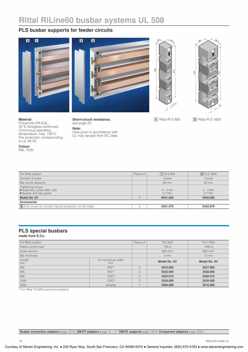
Material:Polyamide (PA 6.6), 25 % fibreglass-reinforced. Continuous operating temperature: max. 130°C. Fire protection corresponding to UL 94-V0.
Colour:RAL 7035
Short-circuit resistance,see page 22.
Note:Data given in accordance with UL may deviate from IEC data.
For Rittal system Packs of PLS 800 PLS 1600
Number of poles 3-pole 3-pole
Bar centre distance 60 mm 60 mm
Tightening torque ● Assembly screw (M6 x 20) ● Busbar anti-slip guard
3 – 5 Nm 0.7 Nm
3 – 5 Nm 0.7 Nm
Model No. SV 4 9341.050 9342.050
Accessories
End covers for contact hazard protection on the sides 2 9341.070 9342.070
1 2
3
PLS special busbars made from E-Cu
For Rittal system Packs of PLS 800 PLS 1600
Rated current max. 700 A 1400 A
Cross-section 300 mm2 900 mm2
Bar thickness 5 mm 10 mm
Lengthmm
For enclosure width mm Model No. SV Model No. SV
495 6001) 3 3524.000 3527.000
695 8001) 3 3525.000 3528.000
895 10001) 3 3525.010 3528.010
1095 12001) 3 3526.000 3529.000
2400 variable 1 3509.000 3516.0001) For Rittal TS 8/ES enclosure systems
Busbar connection adaptors page 12/13 OM/OT adaptors page 14 – 17 OM/OT supports page 18/19 Component adaptors page 20/21
Rittal PLS 800 1 Rittal PLS 1600 2
Courtesy of Steven Engineering, Inc. ● 230 Ryan Way, South San Francisco, CA 94080-6370 ● General Inquiries: (800) 670-4183 ● www.stevenengineering.com
PLS system components for feeder circuits
Rittal RiLine60 busbar systems UL 508
11Rittal RiLine60 UL
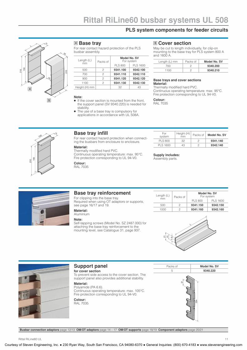
Base trayFor rear contact hazard protection of the PLS busbar assembly.
Note: ● If the cover section is mounted from the front,
the support panel (SV 9340.220) is needed for stability.
● The use of a base tray is compulsory for applications in accordance with UL 508A.
Cover sectionMay be cut to length individually, for clip-on mounting to the base tray for PLS system 800 Aand 1600 A.
Base trays and cover sections Material:Thermally modified hard PVC. Continuous operating temperature: max. 95°C. Fire protection corresponding to UL 94-V0.
Colour:RAL 7035
Length (L) mm Packs of
Model No. SV For system
PLS 800 PLS 1600
500 2 9341.100 9342.100
700 2 9341.110 9342.110
900 2 9341.120 9342.120
1100 2 9341.130 9342.130
Height (H) mm 32 43
4
Length (L) mm Packs of Model No. SV
700 2 9340.200
1100 2 9340.210
5
Base tray infill For rear contact hazard protection when connect-ing the busbars from enclosure to enclosure.
Material:Thermally modified hard PVC. Continuous operating temperature: max. 95°C. Fire protection corresponding to UL 94-V0.
Colour:RAL 7035
Supply includes:Assembly parts.
Forsystem
Height (H)mm Packs of Model No. SV
PLS 800 32 2 9341.140
PLS 1600 43 2 9342.140
Base tray reinforcement For clipping into the base tray. Required when using OT adaptors or supports, see page 16/17 and 19.
Material:Aluminium
Note:Self-tapping screws (Model No. SZ 2487.000) for attaching the base tray reinforcement to the mounting level, see Catalogue 31, page 937.
Length (L) mm Packs of
Model No. SV For system
PLS 800 PLS 1600
500 2 9341.150 9342.150
1000 2 9341.160 9342.160
Support panel for cover section To prevent side access to the cover section. The support panel also provides additional stability.
Material:Polyamide (PA 6.6). Continuous operating temperature: max. 105°C. Fire protection corresponding to UL 94-V0.
Colour:RAL 7035
Packs of Model No. SV
5 9340.220
Busbar connection adaptors page 12/13 OM/OT adaptors page 14 – 17 OM/OT supports page 18/19 Component adaptors page 20/21
4
5
Courtesy of Steven Engineering, Inc. ● 230 Ryan Way, South San Francisco, CA 94080-6370 ● General Inquiries: (800) 670-4183 ● www.stevenengineering.com
Rittal RiLine60 busbar systems UL 508Busbar connection adaptors for feeder circuits
12 Rittal RiLine60 UL
1 2 33 4
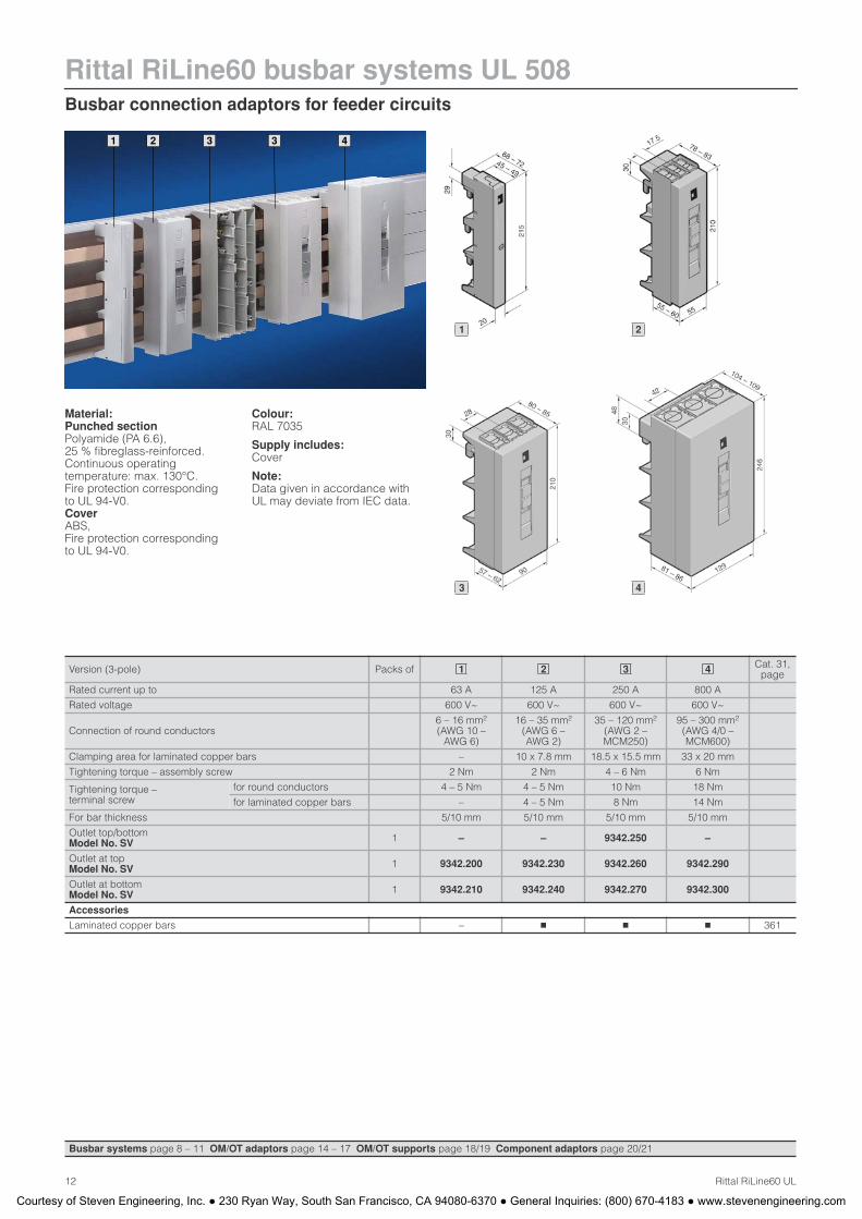
Material:Punched sectionPolyamide (PA 6.6), 25 % fibreglass-reinforced. Continuous operating temperature: max. 130°C. Fire protection corresponding to UL 94-V0. CoverABS,Fire protection corresponding to UL 94-V0.
Colour:RAL 7035
Supply includes:Cover
Note:Data given in accordance with UL may deviate from IEC data.
Version (3-pole) Packs of Cat. 31, page
Rated current up to 63 A 125 A 250 A 800 A
Rated voltage 600 V~ 600 V~ 600 V~ 600 V~
Connection of round conductors 6 – 16 mm2
(AWG 10 – AWG 6)
16 – 35 mm2
(AWG 6 – AWG 2)
35 – 120 mm2
(AWG 2 – MCM250)
95 – 300 mm2
(AWG 4/0 – MCM600)
Clamping area for laminated copper bars – 10 x 7.8 mm 18.5 x 15.5 mm 33 x 20 mm
Tightening torque – assembly screw 2 Nm 2 Nm 4 – 6 Nm 6 Nm
Tightening torque –terminal screw
for round conductors 4 – 5 Nm 4 – 5 Nm 10 Nm 18 Nm
for laminated copper bars – 4 – 5 Nm 8 Nm 14 Nm
For bar thickness 5/10 mm 5/10 mm 5/10 mm 5/10 mm
Outlet top/bottomModel No. SV 1 – – 9342.250 –
Outlet at topModel No. SV 1 9342.200 9342.230 9342.260 9342.290
Outlet at bottomModel No. SV 1 9342.210 9342.240 9342.270 9342.300
Accessories
Laminated copper bars – � � � 361
1 2 3 4
Busbar systems page 8 – 11 OM/OT adaptors page 14 – 17 OM/OT supports page 18/19 Component adaptors page 20/21
1 2
3 4
Courtesy of Steven Engineering, Inc. ● 230 Ryan Way, South San Francisco, CA 94080-6370 ● General Inquiries: (800) 670-4183 ● www.stevenengineering.com
Busbar connection adaptors for feeder circuits
Rittal RiLine60 busbar systems UL 508
13Rittal RiLine60 UL
1 2
1
2
Busbar systems page 8 – 11 OM/OT adaptors page 14 – 17 OM/OT supports page 18/19 Component adaptors page 20/21
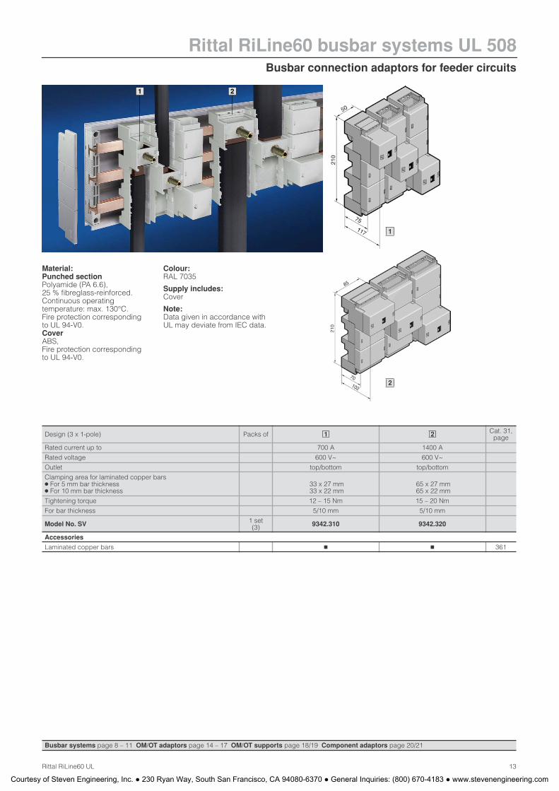
Material:Punched sectionPolyamide (PA 6.6), 25 % fibreglass-reinforced. Continuous operating temperature: max. 130°C. Fire protection corresponding to UL 94-V0. CoverABS,Fire protection corresponding to UL 94-V0.
Colour:RAL 7035
Supply includes:Cover
Note:Data given in accordance with UL may deviate from IEC data.
Design (3 x 1-pole) Packs of Cat. 31, page
Rated current up to 700 A 1400 A
Rated voltage 600 V~ 600 V~
Outlet top/bottom top/bottom
Clamping area for laminated copper bars● For 5 mm bar thickness● For 10 mm bar thickness
33 x 27 mm 33 x 22 mm
65 x 27 mm 65 x 22 mm
Tightening torque 12 – 15 Nm 15 – 20 Nm
For bar thickness 5/10 mm 5/10 mm
Model No. SV 1 set (3) 9342.310 9342.320
Accessories
Laminated copper bars � � 361
1 2
Courtesy of Steven Engineering, Inc. ● 230 Ryan Way, South San Francisco, CA 94080-6370 ● General Inquiries: (800) 670-4183 ● www.stevenengineering.com

Rittal RiLine60 busbar systems UL 508OM adaptors 25 A/32 A/40 A with connection cables for feeder circuits
14 Rittal RiLine60 UL
Material:Polyamide (PA 6.6), 25 % fibreglass-reinforced. Continuous operating temperature: max. 130°C. Fire protection corresponding to UL 94-V0.
Colour:RAL 7035 (punched section)
Note:Overview of market switchgear for the appropriate adaptor, see Innovations 2005/2006,page 213.
Data given in accordance with UL may deviate from IEC data.
Design Packs of Page
Construction width (B) 45 mm 45 mm 45 mm 45 mm 55 mm 75 mm
Length 208 mm 208 mm 208 mm 208 mm 208 mm 208 mm
Rated current up to 25 A 25 A 25 A 32 A 32 A 40 A
Rated voltage 600 V~ 600 V~ 600 V~ 600 V~ 600 V~ 600 V~
Connection cables1) AWG 12 AWG 12 AWG 12 AWG 10 AWG 10 AWG 8
With
Support frame – 45 x 170 mm 45 x 170 mm 45 x 170 mm 55 x 170 mm –
PinBlock – – � – – –
Insert strips – – – – – �
Number of support rails, height
10 mm 1 1 1 1 1 –
7.5 mm – – – – – 2
For bar thickness 5/10 mm Model No. SV 1 9340.310 9340.340 9340.370 9340.350 9340.460 9340.710
Accessories
Connection pin 20 9340.280 9340.280 9340.280 9340.280 9340.280 9340.280 Innov. 78
Insert strip 10 mm 2 9340.290 9340.290 9340.290 9340.290 9340.290 9340.290 Innov. 78
OM support45 x 208 mm 1 9340.260 9340.260 9340.260 9340.260 9340.260 9340.260 18
55 x 208 mm 1 9340.270 9340.270 9340.270 9340.270 9340.270 9340.270 18
Support frame Innov. 78
PinBlock for support frame Innov. 79
PinBlock Plus Innov. 79
Support rails Innov. 801) AWG = American Wire Gauges
AWG 12 = 3.31 mm2 4 mm2
AWG 10 = 5.26 mm2 6 mm2
AWG 8 = 8.37 mm2 10 mm2
1 2 3 4 4 5
Busbar systems page 8 – 11 OM/OT adaptors page 12/13 OM/OT supports page 18/19 Component adaptors page 20/21
1 2 3 4
3 5
1 + 2 4
Courtesy of Steven Engineering, Inc. ● 230 Ryan Way, South San Francisco, CA 94080-6370 ● General Inquiries: (800) 670-4183 ● www.stevenengineering.com
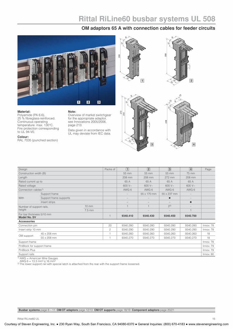
OM adaptors 65 A with connection cables for feeder circuits
Rittal RiLine60 busbar systems UL 508
15Rittal RiLine60 UL
1 2 3
Material:Polyamide (PA 6.6), 25 % fibreglass-reinforced. Continuous operating temperature: max. 130°C. Fire protection corresponding to UL 94-V0.
Colour:RAL 7035 (punched section)
Note:Overview of market switchgear for the appropriate adaptor, see Innovations 2005/2006,page 213.
Data given in accordance with UL may deviate from IEC data.
Design Packs of Page
Construction width (B) 55 mm 55 mm 55 mm 75 mm
Length 208 mm 208 mm 272 mm 208 mm
Rated current up to 65 A 65 A 65 A 65 A
Rated voltage 600 V~ 600 V~ 600 V~ 600 V~
Connection cables1) AWG 6 AWG 6 AWG 6 AWG 6
With
Support frame – 55 x 170 mm 55 x 237 mm –
Support frame supports – – � –
Insert strips – – – �
Number of support rails, height
10 mm 1 1 22) –
7.5 mm – – – 1
For bar thickness 5/10 mm Model No. SV 1 9340.410 9340.430 9340.450 9340.700
Accessories
Connection pin 20 9340.280 9340.280 9340.280 9340.280 Innov. 78
Insert strip 10 mm 2 9340.290 9340.290 9340.290 9340.290 Innov. 78
OM support45 x 208 mm 1 9340.260 9340.260 9340.260 9340.260 18
55 x 208 mm 1 9340.270 9340.270 9340.270 9340.270 18
Support frame Innov. 78
PinBlock for support frame Innov. 79
PinBlock Plus Innov. 79
Support rails Innov. 801) AWG = American Wire Gauges
AWG 6 = 13.3 mm2 16 mm2
2) The lower support rail with special latch is attached from the rear with the support frame loosened.
1 2 3 4
Busbar systems page 8 – 11 OM/OT adaptors page 12/13 OM/OT supports page 18/19 Component adaptors page 20/21
1 2
3 4
Courtesy of Steven Engineering, Inc. ● 230 Ryan Way, South San Francisco, CA 94080-6370 ● General Inquiries: (800) 670-4183 ● www.stevenengineering.com
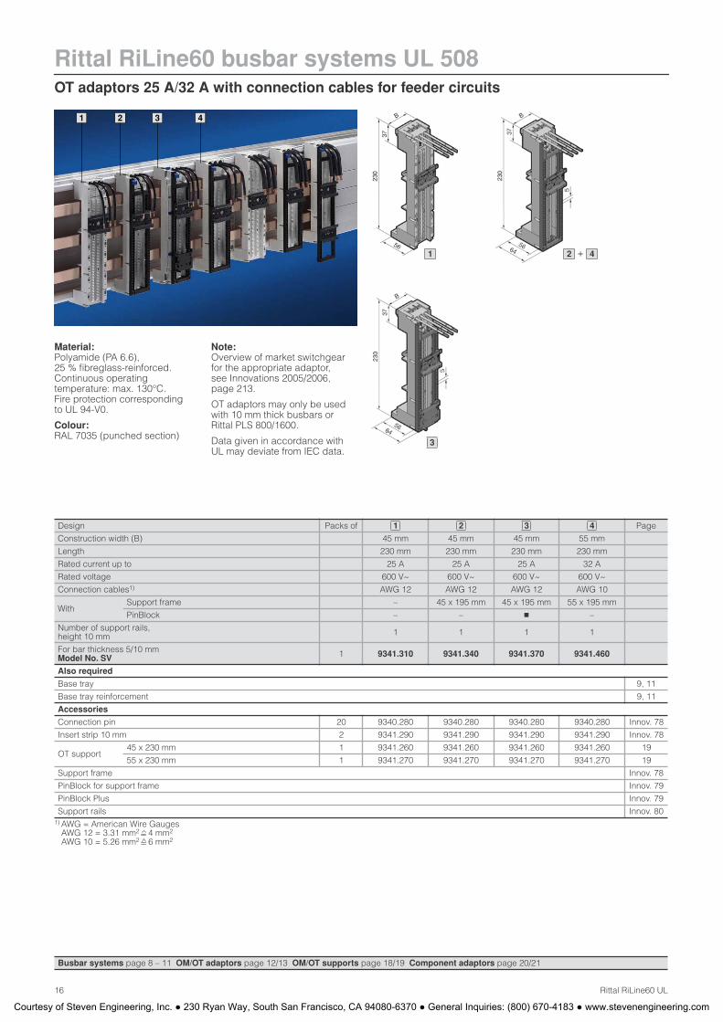
Rittal RiLine60 busbar systems UL 508OT adaptors 25 A/32 A with connection cables for feeder circuits
16 Rittal RiLine60 UL
1 2 3 4
Material:Polyamide (PA 6.6), 25 % fibreglass-reinforced. Continuous operating temperature: max. 130°C. Fire protection corresponding to UL 94-V0.
Colour:RAL 7035 (punched section)
Note:Overview of market switchgear for the appropriate adaptor, see Innovations 2005/2006,page 213.
OT adaptors may only be used with 10 mm thick busbars or Rittal PLS 800/1600.
Data given in accordance with UL may deviate from IEC data.
Design Packs of Page
Construction width (B) 45 mm 45 mm 45 mm 55 mm
Length 230 mm 230 mm 230 mm 230 mm
Rated current up to 25 A 25 A 25 A 32 A
Rated voltage 600 V~ 600 V~ 600 V~ 600 V~
Connection cables1) AWG 12 AWG 12 AWG 12 AWG 10
WithSupport frame – 45 x 195 mm 45 x 195 mm 55 x 195 mm
PinBlock – – � –
Number of support rails, height 10 mm 1 1 1 1
For bar thickness 5/10 mm Model No. SV 1 9341.310 9341.340 9341.370 9341.460
Also required
Base tray 9, 11
Base tray reinforcement 9, 11
Accessories
Connection pin 20 9340.280 9340.280 9340.280 9340.280 Innov. 78
Insert strip 10 mm 2 9341.290 9341.290 9341.290 9341.290 Innov. 78
OT support45 x 230 mm 1 9341.260 9341.260 9341.260 9341.260 19
55 x 230 mm 1 9341.270 9341.270 9341.270 9341.270 19
Support frame Innov. 78
PinBlock for support frame Innov. 79
PinBlock Plus Innov. 79
Support rails Innov. 801) AWG = American Wire Gauges
AWG 12 = 3.31 mm2 4 mm2
AWG 10 = 5.26 mm2 6 mm2
1 2 3 4
Busbar systems page 8 – 11 OM/OT adaptors page 12/13 OM/OT supports page 18/19 Component adaptors page 20/21
1 + 2 4
3
Courtesy of Steven Engineering, Inc. ● 230 Ryan Way, South San Francisco, CA 94080-6370 ● General Inquiries: (800) 670-4183 ● www.stevenengineering.com

OT adaptors 65 A with connection cables for feeder circuits
Rittal RiLine60 busbar systems UL 508
17Rittal RiLine60 UL
1 2 3
Material:Polyamide (PA 6.6), 25 % fibreglass-reinforced. Continuous operating temperature: max. 130°C. Fire protection corresponding to UL 94-V0.
Colour:RAL 7035 (punched section)
Note:Overview of market switchgear for the appropriate adaptor, see Innovations 2005/2006, page 213.
OT adaptors may only be used with 10 mm thick busbars or Rittal PLS 800/1600.
Data given in accordance with UL may deviate from IEC data.
Design Packs of Page
Construction width (B) 55 mm 55 mm 55 mm
Length 230 mm 230 mm 272 mm
Rated current up to 65 A 65 A 65 A
Rated voltage 600 V~ 600 V~ 600 V~
Connection cables1) AWG 6 AWG 6 AWG 6
WithSupport frame – 55 x 195 mm 55 x 237 mm
PinBlock – – –
Number of support rails, height 10 mm 1 1 22)
For bar thickness 5/10 mm Model No. SV 1 9341.410 9341.430 9341.450
Also required
Base tray 9, 11
Base tray reinforcement 9, 11
Accessories
Connection pin 20 9340.280 9340.280 9340.280 Innov. 78
Insert strip 10 mm 2 9341.290 9341.290 9341.290 Innov. 78
OT support45 x 230 mm 1 9341.260 9341.260 9341.260 19
55 x 230 mm 1 9341.270 9341.270 9341.270 19
Support frame Innov. 78
PinBlock for support frame Innov. 79
PinBlock Plus Innov. 79
Support rails Innov. 801) AWG = American Wire Gauges
AWG 6 = 13.3 mm2 16 mm2
2) The lower support rail with special latch is attached from the rear with the support frame loosened.
1 2 3
Busbar systems page 8 – 11 OM/OT adaptors page 12/13 OM/OT supports page 18/19 Component adaptors page 20/21
1 2
3
Courtesy of Steven Engineering, Inc. ● 230 Ryan Way, South San Francisco, CA 94080-6370 ● General Inquiries: (800) 670-4183 ● www.stevenengineering.com
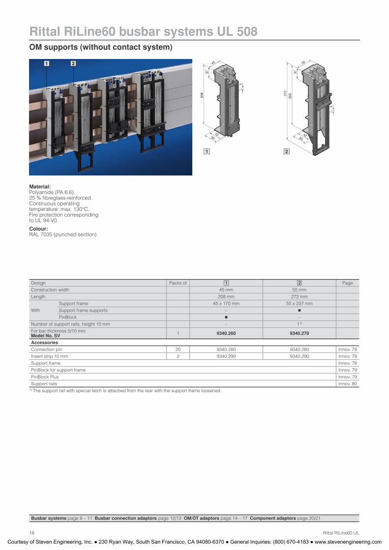
Rittal RiLine60 busbar systems UL 508OM supports (without contact system)
18 Rittal RiLine60 UL
1 2
Material:Polyamide (PA 6.6), 25 % fibreglass-reinforced. Continuous operating temperature: max. 130°C. Fire protection corresponding to UL 94-V0.
Colour:RAL 7035 (punched section)
Design Packs of Page
Construction width 45 mm 55 mm
Length 208 mm 272 mm
With
Support frame 45 x 170 mm 55 x 237 mm
Support frame supports – �
PinBlock � –
Number of support rails, height 10 mm – 11)
For bar thickness 5/10 mm Model No. SV 1 9340.260 9340.270
Accessories
Connection pin 20 9340.280 9340.280 Innov. 78
Insert strip 10 mm 2 9340.290 9340.290 Innov. 78
Support frame Innov. 78
PinBlock for support frame Innov. 79
PinBlock Plus Innov. 79
Support rails Innov. 801) The support rail with special latch is attached from the rear with the support frame loosened.
1 2
Busbar systems page 8 – 11 Busbar connection adaptors page 12/13 OM/OT adaptors page 14 – 17 Component adaptors page 20/21
1 2
Courtesy of Steven Engineering, Inc. ● 230 Ryan Way, South San Francisco, CA 94080-6370 ● General Inquiries: (800) 670-4183 ● www.stevenengineering.com
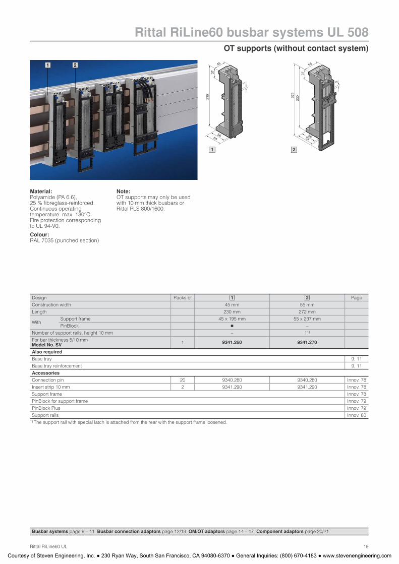
OT supports (without contact system)
Rittal RiLine60 busbar systems UL 508
19Rittal RiLine60 UL
1 2
Material:Polyamide (PA 6.6), 25 % fibreglass-reinforced. Continuous operating temperature: max. 130°C. Fire protection corresponding to UL 94-V0.
Colour:RAL 7035 (punched section)
Note:OT supports may only be used with 10 mm thick busbars or Rittal PLS 800/1600.
Design Packs of Page
Construction width 45 mm 55 mm
Length 230 mm 272 mm
WithSupport frame 45 x 195 mm 55 x 237 mm
PinBlock � –
Number of support rails, height 10 mm – 11)
For bar thickness 5/10 mm Model No. SV 1 9341.260 9341.270
Also required
Base tray 9, 11
Base tray reinforcement 9, 11
Accessories
Connection pin 20 9340.280 9340.280 Innov. 78
Insert strip 10 mm 2 9341.290 9341.290 Innov. 78
Support frame Innov. 78
PinBlock for support frame Innov. 79
PinBlock Plus Innov. 79
Support rails Innov. 801) The support rail with special latch is attached from the rear with the support frame loosened.
1 2
Busbar systems page 8 – 11 Busbar connection adaptors page 12/13 OM/OT adaptors page 14 – 17 Component adaptors page 20/21
1 2
Courtesy of Steven Engineering, Inc. ● 230 Ryan Way, South San Francisco, CA 94080-6370 ● General Inquiries: (800) 670-4183 ● www.stevenengineering.com
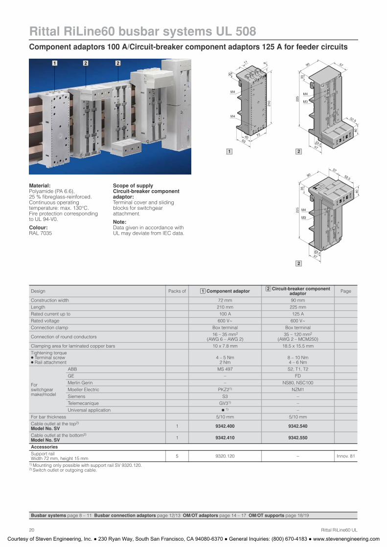
Rittal RiLine60 busbar systems UL 508Component adaptors 100 A/Circuit-breaker component adaptors 125 A for feeder circuits
20 Rittal RiLine60 UL
1 22
Material:Polyamide (PA 6.6), 25 % fibreglass-reinforced. Continuous operating temperature: max. 130°C. Fire protection corresponding to UL 94-V0.
Colour:RAL 7035
Scope of supply Circuit-breaker component adaptor:Terminal cover and sliding blocks for switchgear attachment.
Note:Data given in accordance with UL may deviate from IEC data.
Design Packs of Component adaptor Circuit-breaker component adaptor Page
Construction width 72 mm 90 mm
Length 210 mm 225 mm
Rated current up to 100 A 125 A
Rated voltage 600 V~ 600 V~
Connection clamp Box terminal Box terminal
Connection of round conductors 16 – 35 mm2
(AWG 6 – AWG 2)35 – 120 mm2
(AWG 2 – MCM250)
Clamping area for laminated copper bars 10 x 7.8 mm 18.5 x 15.5 mm
Tightening torque ● Terminal screw ● Rail attachment
4 – 5 Nm 2 Nm
8 – 10 Nm 4 – 6 Nm
Forswitchgearmake/model
ABB MS 497 S2, T1, T2
GE – FD
Merlin Gerin – NS80, NSC100
Moeller Electric PKZ21) NZM1
Siemens S3 –
Telemecanique GV31) –
Universal application � 1) –
For bar thickness 5/10 mm 5/10 mm
Cable outlet at the top2)
Model No. SV 1 9342.400 9342.540
Cable outlet at the bottom2)
Model No. SV 1 9342.410 9342.550
Accessories
Support rail Width 72 mm, height 15 mm 5 9320.120 – Innov. 81
1) Mounting only possible with support rail SV 9320.120. 2) Switch outlet or outgoing cable.
1 2
Busbar systems page 8 – 11 Busbar connection adaptors page 12/13 OM/OT adaptors page 14 – 17 OM/OT supports page 18/19
1 2
2
Courtesy of Steven Engineering, Inc. ● 230 Ryan Way, South San Francisco, CA 94080-6370 ● General Inquiries: (800) 670-4183 ● www.stevenengineering.com
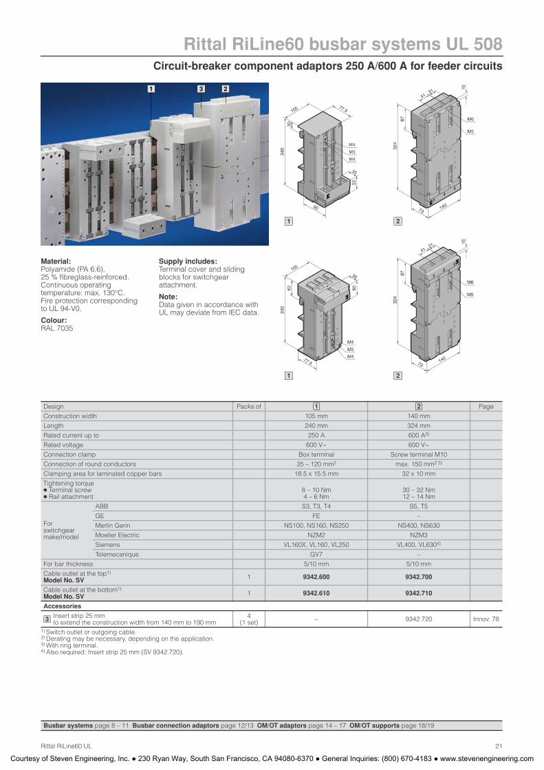
Circuit-breaker component adaptors 250 A/600 A for feeder circuits
Rittal RiLine60 busbar systems UL 508
21Rittal RiLine60 UL
1 23
Material:Polyamide (PA 6.6), 25 % fibreglass-reinforced. Continuous operating temperature: max. 130°C. Fire protection corresponding to UL 94-V0.
Colour:RAL 7035
Supply includes:Terminal cover and sliding blocks for switchgear attachment.
Note:Data given in accordance with UL may deviate from IEC data.
Design Packs of Page
Construction width 105 mm 140 mm
Length 240 mm 324 mm
Rated current up to 250 A 600 A2)
Rated voltage 600 V~ 600 V~
Connection clamp Box terminal Screw terminal M10
Connection of round conductors 35 – 120 mm2 max. 150 mm2 3)
Clamping area for laminated copper bars 18.5 x 15.5 mm 32 x 10 mm
Tightening torque ● Terminal screw ● Rail attachment
8 – 10 Nm 4 – 6 Nm
30 – 32 Nm 12 – 14 Nm
Forswitchgearmake/model
ABB S3, T3, T4 S5, T5
GE FE –
Merlin Gerin NS100, NS160, NS250 NS400, NS630
Moeller Electric NZM2 NZM3
Siemens VL160X, VL160, VL250 VL400, VL6304)
Telemecanique GV7 –
For bar thickness 5/10 mm 5/10 mm
Cable outlet at the top1)
Model No. SV 1 9342.600 9342.700
Cable outlet at the bottom1)
Model No. SV 1 9342.610 9342.710
Accessories
Insert strip 25 mm to extend the construction width from 140 mm to 190 mm
4(1 set) – 9342.720 Innov. 78
1) Switch outlet or outgoing cable. 2) Derating may be necessary, depending on the application.3) With ring terminal. 4) Also required: Insert strip 25 mm (SV 9342.720).
1 2
3
Busbar systems page 8 – 11 Busbar connection adaptors page 12/13 OM/OT adaptors page 14 – 17 OM/OT supports page 18/19
1 2
21
Courtesy of Steven Engineering, Inc. ● 230 Ryan Way, South San Francisco, CA 94080-6370 ● General Inquiries: (800) 670-4183 ● www.stevenengineering.com
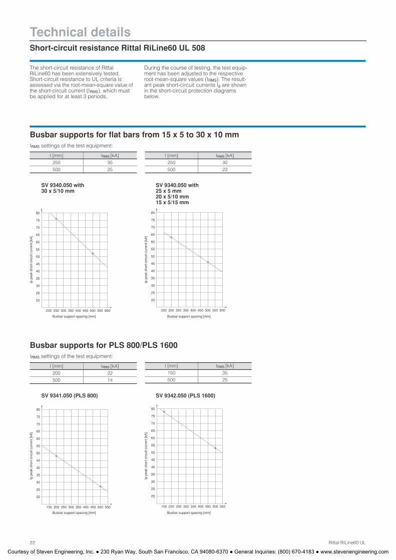
Technical detailsShort-circuit resistance Rittal RiLine60 UL 508
22 Rittal RiLine60 UL
The short-circuit resistance of Rittal RiLine60 has been extensively tested. Short-circuit resistance to UL criteria is assessed via the root-mean-square value of the short-circuit current (IRMS), which must be applied for at least 3 periods.
During the course of testing, the test equip-ment has been adjusted to the respective root-mean-square values (IRMS). The result-ant peak short-circuit currents Ip are shown in the short-circuit protection diagrams below.
30
25
20
65
60
55
45
35
40
50
80
75
70
350200 250 300 450400 500 550150450
20
25
30
200 250 300 350 400
50
40
35
45
55
60
65
500
70
75
80
550150
Ip p
eak
shor
t-ci
rcui
t cur
rent
[kA
]
Busbar support spacing [mm]
200 250 450350 400300 600500 550
30
35
45
40
60
65
55
50
70
80
75
25
20
Busbar supports for flat bars from 15 x 5 to 30 x 10 mmIRMS settings of the test equipment:
I [mm] IRMS [kA]
250 35
500 25
Ip p
eak
shor
t-ci
rcui
t cur
rent
[kA
]
Busbar support spacing [mm]
I [mm] IRMS [kA]
250 30
500 22
20
25
35
30
450300200 250 350 400 550500 600
80
75
70
65
60
55
50
45
40
Ip p
eak
shor
t-ci
rcui
t cur
rent
[kA
]
Busbar support spacing [mm]
Busbar supports for PLS 800/PLS 1600IRMS settings of the test equipment:
I [mm] IRMS [kA]
200 22
500 14
I [mm] IRMS [kA]
150 35
500 25
Ip p
eak
shor
t-ci
rcui
t cur
rent
[kA
]
Busbar support spacing [mm]
SV 9340.050 with 30 x 5/10 mm
SV 9340.050 with 25 x 5 mm 20 x 5/10 mm 15 x 5/15 mm
SV 9341.050 (PLS 800) SV 9342.050 (PLS 1600)
Courtesy of Steven Engineering, Inc. ● 230 Ryan Way, South San Francisco, CA 94080-6370 ● General Inquiries: (800) 670-4183 ● www.stevenengineering.com
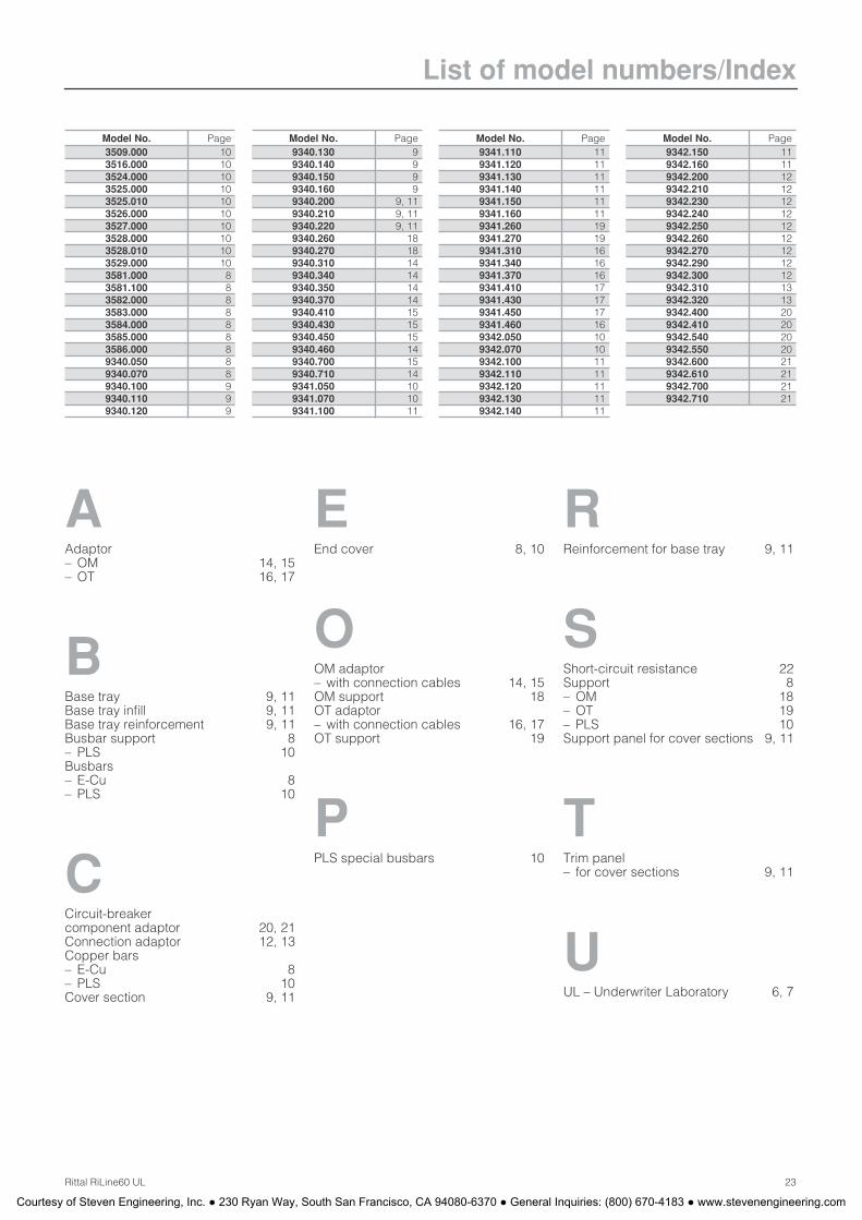
List of model numbers/Index
23Rittal RiLine60 UL
Model No. Page3509.000 103516.000 103524.000 103525.000 103525.010 103526.000 103527.000 103528.000 103528.010 103529.000 103581.000 83581.100 83582.000 83583.000 83584.000 83585.000 83586.000 89340.050 89340.070 89340.100 99340.110 99340.120 9
9340.130 99340.140 99340.150 99340.160 99340.200 9, 119340.210 9, 119340.220 9, 119340.260 189340.270 189340.310 149340.340 149340.350 149340.370 149340.410 159340.430 159340.450 159340.460 149340.700 159340.710 149341.050 109341.070 109341.100 11
Model No. Page9341.110 119341.120 119341.130 119341.140 119341.150 119341.160 119341.260 199341.270 199341.310 169341.340 169341.370 169341.410 179341.430 179341.450 179341.460 169342.050 109342.070 109342.100 119342.110 119342.120 119342.130 119342.140 11
Model No. Page9342.150 119342.160 119342.200 129342.210 129342.230 129342.240 129342.250 129342.260 129342.270 129342.290 129342.300 129342.310 139342.320 139342.400 209342.410 209342.540 209342.550 209342.600 219342.610 219342.700 219342.710 21
Model No. Page
AAdaptor– OM 14, 15– OT 16, 17
BBase tray 9, 11Base tray infill 9, 11Base tray reinforcement 9, 11Busbar support 8– PLS 10Busbars– E-Cu 8– PLS 10
CCircuit-breakercomponent adaptor 20, 21Connection adaptor 12, 13Copper bars– E-Cu 8– PLS 10Cover section 9, 11
EEnd cover 8, 10
OOM adaptor– with connection cables 14, 15OM support 18OT adaptor– with connection cables 16, 17OT support 19
PPLS special busbars 10
RReinforcement for base tray 9, 11
SShort-circuit resistance 22Support 8– OM 18– OT 19– PLS 10Support panel for cover sections 9, 11
TTrim panel– for cover sections 9, 11
UUL – Underwriter Laboratory 6, 7
Courtesy of Steven Engineering, Inc. ● 230 Ryan Way, South San Francisco, CA 94080-6370 ● General Inquiries: (800) 670-4183 ● www.stevenengineering.com
Switch to perfection
R
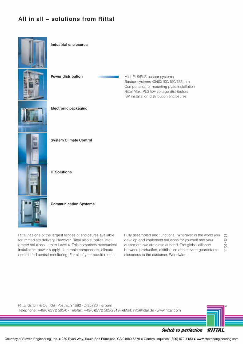
All in all – solutions from Rittal
Rittal has one of the largest ranges of enclosures available for immediate delivery. However, Rittal also supplies inte-grated solutions – up to Level 4. This comprises mechanical installation, power supply, electronic components, climate control and central monitoring. For all of your requirements.
Fully assembled and functional. Wherever in the world you develop and implement solutions for yourself and your customers, we are close at hand. The global alliance between production, distribution and service guarantees closeness to the customer. Worldwide!
11/0
6
� E46
1
Mini-PLS/PLS busbar systems Busbar systems 40/60/100/150/185 mm Components for mounting plate installation Rittal Maxi-PLS low voltage distributorsISV installation distribution enclosures
Electronic packaging
IT Solutions
Communication Systems
System Climate Control
Power distribution
Industrial enclosures
Rittal GmbH & Co. KG
� Postfach 1662
� D-35726 HerbornTelephone: +49(0)2772 505-0
� Telefax: +49(0)2772 505-2319
� eMail: [email protected]
� www.rittal.com
Courtesy of Steven Engineering, Inc. ● 230 Ryan Way, South San Francisco, CA 94080-6370 ● General Inquiries: (800) 670-4183 ● www.stevenengineering.com


