Imperial Journal of Interdisciplinary Research (IJIR) Vol.2, Issue-2 , 2016 ISSN : 2454-1362 , http://www.onlinejournal.in
Imperial Journal of Interdisciplinary Research (IJIR) Page 203
Review On The Design Of Pcm Based
Thermal Energy Storage Systems
P.Pradeep Castro Assistant Professor, MAM School of Engg
P.Karthick Selvam Assistant Professor, MAM School of Engg
C.Suthan Assistant Professor, MAM School of Engg
Abstract—Thermal Energy Storage has become very
important in the recent years since it balances the energy
demand and improves the efficiency of the solar systems. It
is important that the thermal energy storage systems have
the necessary characteristics to improve the performance of
the storage systems. Usage of Phase change materials for
energy storage provides a great benefit but their low
thermal conductivity becomes a major drawback. This can
be compensated with the use of phase change material in an
appropriate design for effective functioning of the system.
This review article summarizes the recent designs of thermal
energy storage systems containing Phase Change Material
that has been adopted for effective energy storage.
Keywords— PCM, Thermal Conductivity, Energy
Storage, Phase Change, Latent Heat
I. INTRODUCTION
Solar energy is a basic need of living plants and
human beings on the earth. It is intermittent in nature, eco-
friendly and non-polluting energy. For effective utilization
of the solar energy, it is highly important to develop solar
thermal energy storage systems. Thermal energy storage is
essential for both domestic water heating and space heating
applications and for industrial applications. Energy can be
stored by the heating, melting, or vaporization of material
and the energy is made available as heat, when reversed.
The size of a storage system is related to the energy
density or the amount of energy stored per unit mass of the
storage material. Larger energy density provides smaller
storage size and lesser amount of storage material. This
paper summarizes the designs that have been used by
several authors in order to improve the performance of the
TES system for various practical applications.
II. DESIGN OF PCM STORAGE
T. Kousksou et. al [1] investigated PCM in the
form of small cylindrical containers for the application in
Solar Domestic Hot Water (SDHW). PCM was implemented
in cylindrical form of diameter 0.04m in order to increase
the surface area for heat transfer. The PCM used in the
investigation was a composite of NaOAc_3H2O-graphite
with the melting point of 57.31°C. On analysis, the authors
found that the Phase change temperature of the composite
PCM was higher. Hence another PCM with a phase change
temperature of 50°C was used and investigated which
indicated improved performance. Further suggestions were
made by the authors that apart from the geometry of the
PCM, the phase change temperature of the selected PCM,
environmental conditions were also important.
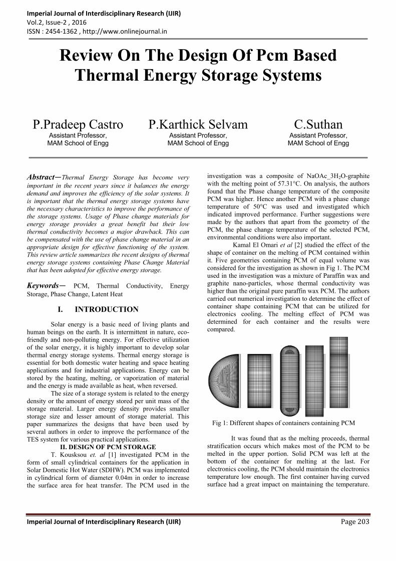
Kamal El Omari et al [2] studied the effect of the
shape of container on the melting of PCM contained within
it. Five geometries containing PCM of equal volume was
considered for the investigation as shown in Fig 1. The PCM
used in the investigation was a mixture of Paraffin wax and
graphite nano-particles, whose thermal conductivity was
higher than the original pure paraffin wax PCM. The authors
carried out numerical investigation to determine the effect of
container shape containing PCM that can be utilized for
electronics cooling. The melting effect of PCM was
determined for each container and the results were
compared.
Fig 1: Different shapes of containers containing PCM
It was found that as the melting proceeds, thermal
stratification occurs which makes most of the PCM to be
melted in the upper portion. Solid PCM was left at the
bottom of the container for melting at the last. For
electronics cooling, the PCM should maintain the electronics
temperature low enough. The first container having curved
surface had a great impact on maintaining the temperature.

Imperial Journal of Interdisciplinary Research (IJIR) Vol.2, Issue-2 , 2016 ISSN : 2454-1362 , http://www.onlinejournal.in
Imperial Journal of Interdisciplinary Research (IJIR) Page 204
Thus the authors conclude that when considering the
geometry of a PCM container, it is better to avoid sharp
corners and provide smooth curves to support complete
melting of the PCM.
E. Halawa and W. Saman [3] made a numerical
study on the performance of PCM based TES for space
heating applications. The storage unit was made of 45
rectangular slabs of length 1m and width 0.89m. Numerical
investigation was conducted with variations in the thickness
of the PCM slab and air gaps between the slabs. The PCM
used in the slab form is Calcium chloride hexahydrate
(CaCl2.H2O) with melting temperature of 28°C. The results
of the experiment shows that the thickness of the slab had
impact on the heat transfer rates. Thicker slabs reduced the
heat transfer rates which led to the increased melting and
freezing time, but with a higher mass flow rate the melting
and freezing time was reduced. Hence the authors come to a
conclusion regarding the importance of the design chosen
for energy storage.
57 vertical PVC tubes containing encapsulated
PCM were used by A. de Gracia et al [4] in hot water
cylinder to reduce the amount of electricity used for
producing hot water The tubes containing PCM had
dimensions of length 0.75 m and 0.04 m diameter placed
inside the hot water cylinder of length 1.02 m and 0.474 m
insulated with polyurethane of thickness 5cm. On examining
the results of the different cases, it was found that the PCM
in smaller diameter of PVC tubes was melted and solidified
faster. The usage of PCM in the hot water cylinder reduces
the electricity consumed for heating the water.
Mehmet et al [5] experimentally investigated the
influence of natural convection on the design and flow
parameters of a shell and tube heat exchanger. Two
concentric tubes formed the heat exchanger. The interior
cylinder was 400mm long with internal and external
diameters of 15mm and 25mm respectively. The exterior
cylindrical tube material and diameters were varied and
investigated, while the shell material was Plexiglas. The
tube materials considered for the investigation were copper,
stainless steel, and Polyethylene (PE-32). The heat
exchanger was insulated with 15mm of armaflex and 30mm
of glass wool. Water was used as the PCM and Ethylene-
glycol-water solution was used as the HTF. Charging and
discharging experiments were conducted on the heat
exchanger with different values of HTF flow rate and inlet
temperatures. Charging process included the complete
freezing of water and discharging the complete melting of
the ice under environmental conditions. The experimental
results indicated that conduction process followed by natural
convection dominated the charging and discharging process
as the buoyancy forces came into play. As a result, two
regions are formed along the interference, top layer called as
natural convection dominant region and the other bottom
region called conduction dominant region. The freezing
process results in the formation of ice, which is affected by
the axial flow direction. The influence of HTF flow rate and
inlet temperature was determined and resulted that increase
in HTF flow rate and decrease in inlet temperature leads to
higher energy storage. It was also found from the results that
the thermal conductivity of the tube material affects the
energy storage. With the use of material of higher
conductivity for the tube, the energy stored was high.
Considering the influence of the tube diameter on the energy
storage capacity of the system, the authors found that the
solidification speed was slower with the shell diameter of
114mm. When the shell diameter was increased to 190mm,
thermal stratification was induced leading to higher energy
storage. It could be understood from the experimental
investigation that along with the HTF flow rate, inlet
temperature, the design parameters of the heat exchanger for
energy storage must also be considered so that a greater
amount of energy can be stored.
M.J Huang et al [6] examined the performance of
Phase Change Slurries (PCS) in residential energy storage
applications along with a helical coil heat exchanger. A
Phase Change Slurry (PCS) consists of small
microencapsulated PCM particles in a fluid medium. The
PCS serves as an energy storage medium with the help of
PCM present in them and also as a HTF, used for improving
the heat transfer. The coiled heat exchanger was fabricated
for an outer diameter of 200mm with copper tubes having
outer diameter as 22mm. The coiled heat exchanger was
placed at the bottom end of the tank whose dimensions were
with diameter as 0.270m and height 1m. The tank was well
insulated. The PCS used in the investigation had paraffin
with melting point of 70°C enclosed within plastic capsules
of 2 to 8µm. The authors compared the performance of the
storage system when PCS as the storage medium with water
as storage medium. Temperature variations were measured
with natural circulation of water and with flow rates of
20kgmin-1 and 30kgmin-1. Results were obtained that energy
storage is faster with flow rate of 30kgmin-1 and convection
process dominated the heat transfer when water is used as
the storage medium. Similar analysis was made when the
PCS was used as the storage medium. In this case, the
volume concentration of the PCS had a major role. 25%
volume concentration of slurry produced similar results that
were closer to the case of water as storage medium. But
when 50% volume concentration of slurry was used, the heat
transfer and increase in temperature was much low. This is
due to the low thermal conductivity of the PCM, high
viscosity and high specific heat. Natural convection was
observed around the helical coil heat exchanger. As a result,
the PCS around the heat exchanger got heated up and
became less dense and started to move to the top of the tank
and the denser PCS started heating and the process
continued. From the results obtained, the authors come to a
conclusion that PCS with 50% of volume concentration are
not suitable for energy storage applications. Also it is found
that the size and location of the heat exchanger had a
Imperial Journal of Interdisciplinary Research (IJIR) Vol.2, Issue-2 , 2016 ISSN : 2454-1362 , http://www.onlinejournal.in
Imperial Journal of Interdisciplinary Research (IJIR) Page 205
significant influence in the energy storage performance of
the system.
Isabel Cerona et al [7] developed a new tile
containing PCM for cooling of room. The newly designed
tile was of length 660mm and width 660mm. It consists of
four pieces of pure clay of thickness 20mm, a metal
container of 32mm thickness containing 4.8l of PCM
followed by a thermal insulation of 22mm thick. The Tile
was experimentally investigated and the results were
compared with the tile without PCM. Experimental
evaluation took about 60 days and found that the tiles stored
the excess heat energy and maintained the room temperature
around 4°C to 10°C. The tile was found useful in storing the
heat energy and maintaining the room temperature. Also the
tiles exposed to higher temperatures had a higher
effectiveness. Similarly Chengbin Zhang et al [8] used PCM
in brick walls to control the temperature fluctuations of
buildings. Wei-Biao Ye et al [9] described the detail process
of thermal storage and release in a aluminium plate-fin
storage unit. Numerical investigation was carried for plate-
fin thermal storage/release unit using paraffin PCM for
determining the effect of temperature difference. The
authors described the detailed thermal storage/release
process that might be useful for practical applications. The
storage/release unit consisted square channel with inner
plates and outer plates. The inner plates carried water as the
HTF and paraffin in the fins space. The height and width of
the fins were 12mm and 1.6mm while the width of the PCM
layer was 4mm. When heated, PCM closer to the fin and
plate wall melts and the liquid is affected by gravitational
force as well as buoyancy forces. Gravitational force comes
to play with lower temperatures while buoyancy forces
affect the liquid PCM during greater temperatures which
makes the liquid PCM to flow upwards. With higher
temperatures, heat transfer takes place from bottom plate to
the top and the melting occurs and a circulating flow is
observed closer to the bottom heating wall which leads to
higher melting rates. The results show that with larger
temperature differences, the liquid fraction development rate
was quicker leading to shorter completion time. Also
increase in temperature difference causes the increase in
temperature gradient which finally results in the increase of
heat flux. Higher heat flux leads to reduced thermal storage
time. Similarly during the energy release process, volume of
the PCM reduces and it is noted that a part of the un-
solidified PCM remains for a long time. At the end of the
release process, the heat flux reaches to zero indicating the
end stage. The authors state that the dimensions of the
storage unit can also induce natural convection that
increases the heat transfer coefficient.
S.F. Hosseinizadeh et al [10] has done an detailed
experimental and numerical investigation on the effect of
number of fins, fin thickness, fin height, power input level
of PCM based heat sinks used in the thermal management of
electronic components. The heat sinks had a common
dimension of 60mm*40mm made aluminium 6061 alloy
with different dimensions of fins. With power inputs of
25W, 35W and 45W, it was observed that higher the power
input, the higher the heat absorbed was. With increase in
number of fins, the volume of PCM decreases and as a result
melting time is reduced. Similarly a thicker fin has lower
volume of PCM which causes delayed melting of PCM.
Increase in thickness of fins also reduces the thermal
resistance of fins, which obviously leads to delayed melting
of PCM. An increase in height of the fins delays the start of
melting and the melting period which leads to increased
usage time of the electronics component.
Nithyanandam and Pitchumani [11] attempted to
investigate the influence of heat pipe, parametric and
geometric parameters on the performance of a shell and tube
latent thermal energy storage systems with embedded heat
pipes. The LTES used in the investigation was a high
temperature LTES commonly used in CSP plants. The
LTES was examined as two modules. Module 1 had the
HTF flowing through the pipe surrounded by PCM, while
Module 2 had the PCM contained within the tube and the
HTF was made to flow transversely to the axis of the tube.
The arrangement was in such a way that the surface area
exposed to the HTF was equal for both the modules. The
geometric parameters considered by the authors were length
of module (0.08 to 0.2), length of evaporator section of the
heat pipe (0.2 to 0.4), length of condenser section of the heat
pipe (0.05 to 0.243), outer radius of the tube (0.2 to 0.4),
radius of vapor core of heat pipe (0.007 to 0.038), thickness
of the wick of heat pipe (0.007 to 0.032). The influence of
the above parameters on the performance of the LTES was
determined during charging and discharging process. The
mass flow rate values taken for the investigation were 0.589
kg/s, 2.80 kg/s, and 5.89 kg/s. During the charging with
module 1, the combined effect of natural convection and
conduction came into play. The performance of the LTES
with the above parameters was determined. With increase in
the mass flow rate, the melting rate of PCM increased with
increase in the melt fraction as a result of which the
charging rate of the PCM was found to be increased. Thus
by increasing the mass flow rate, the thermal performance of
the LTES was found to be decreasing. Considering the
module length, the authors found that with lower values of
the module length, which leads to horizontal configuration
of closely packed heat pipes will result in an improved
performance of the LTES system. The heat pipes with
longer evaporator section seem to produce a higher charging
rate with improved effectiveness of the LTES, which was
similar with the case of increasing the length of the
condenser section. The increase lead to a larger surface area
for the melting of the PCM in a slower process due to which
the onset of natural convection was delayed leading to an
improved effectiveness. When the tube radius was
increased, the effectiveness of the LTES decreased, but the
Imperial Journal of Interdisciplinary Research (IJIR) Vol.2, Issue-2 , 2016 ISSN : 2454-1362 , http://www.onlinejournal.in
Imperial Journal of Interdisciplinary Research (IJIR) Page 206
increase in the vapor core radius of the heat pipe increased
the effectiveness of the LTES than the increase of the wick
thickness of the heat pipe. The results were almost the same
when examined with module 2. The results obtained for
charging with module 1 and 2 was close to the results of
discharging process. The authors also tried and succeeded in
identifying the optimum design with operating parameters
which would increase the charging/discharging
effectiveness, effective charging/discharging rate and
effective energy transfer rate for charging/discharging.
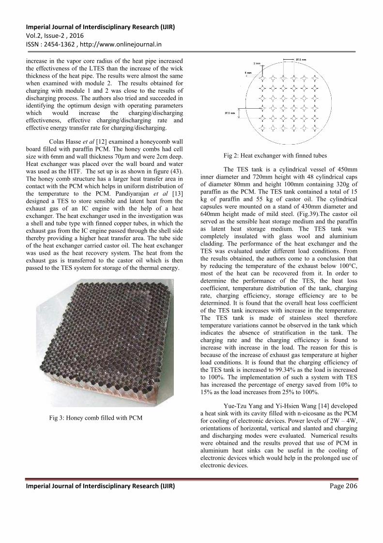
Colas Hasse et al [12] examined a honeycomb wall
board filled with paraffin PCM. The honey combs had cell
size with 6mm and wall thickness 70µm and were 2cm deep.
Heat exchanger was placed over the wall board and water
was used as the HTF. The set up is as shown in figure (43).
The honey comb structure has a larger heat transfer area in
contact with the PCM which helps in uniform distribution of
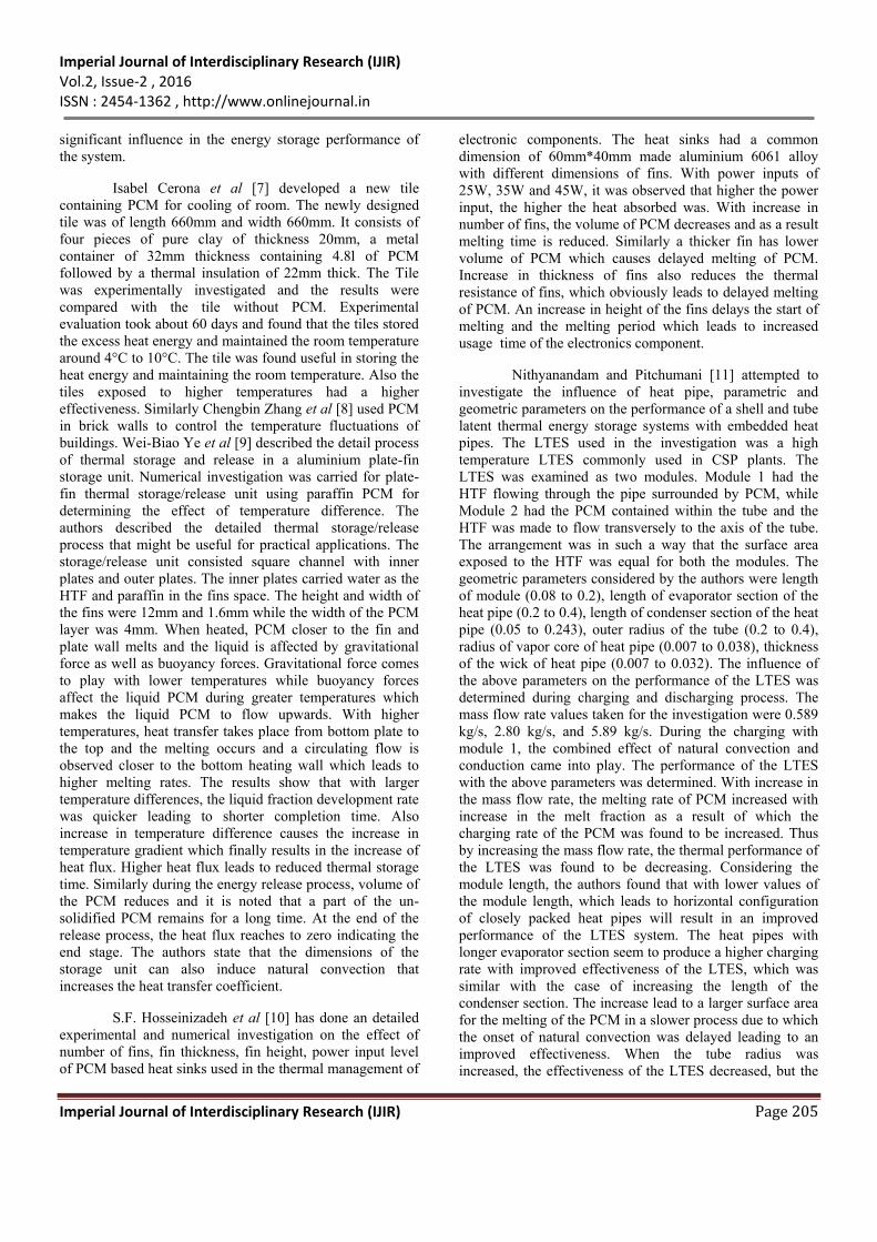
the temperature to the PCM. Pandiyarajan et al [13]
designed a TES to store sensible and latent heat from the
exhaust gas of an IC engine with the help of a heat
exchanger. The heat exchanger used in the investigation was
a shell and tube type with finned copper tubes, in which the
exhaust gas from the IC engine passed through the shell side
thereby providing a higher heat transfer area. The tube side
of the heat exchanger carried castor oil. The heat exchanger
was used as the heat recovery system. The heat from the
exhaust gas is transferred to the castor oil which is then
passed to the TES system for storage of the thermal energy.
Fig 3: Honey comb filled with PCM
Fig 2: Heat exchanger with finned tubes
The TES tank is a cylindrical vessel of 450mm
inner diameter and 720mm height with 48 cylindrical caps
of diameter 80mm and height 100mm containing 320g of
paraffin as the PCM. The TES tank contained a total of 15
kg of paraffin and 55 kg of castor oil. The cylindrical
capsules were mounted on a stand of 430mm diameter and
640mm height made of mild steel. (Fig.39).The castor oil
served as the sensible heat storage medium and the paraffin
as latent heat storage medium. The TES tank was
completely insulated with glass wool and aluminium
cladding. The performance of the heat exchanger and the
TES was evaluated under different load conditions. From
the results obtained, the authors come to a conclusion that
by reducing the temperature of the exhaust below 100°C,
most of the heat can be recovered from it. In order to
determine the performance of the TES, the heat loss
coefficient, temperature distribution of the tank, charging
rate, charging efficiency, storage efficiency are to be
determined. It is found that the overall heat loss coefficient
of the TES tank increases with increase in the temperature.
The TES tank is made of stainless steel therefore
temperature variations cannot be observed in the tank which
indicates the absence of stratification in the tank. The
charging rate and the charging efficiency is found to
increase with increase in the load. The reason for this is
because of the increase of exhaust gas temperature at higher
load conditions. It is found that the charging efficiency of
the TES tank is increased to 99.34% as the load is increased
to 100%. The implementation of such a system with TES
has increased the percentage of energy saved from 10% to
15% as the load increases from 25% to 100%.
Yue-Tzu Yang and Yi-Hsien Wang [14] developed
a heat sink with its cavity filled with n-eicosane as the PCM
for cooling of electronic devices. Power levels of 2W – 4W,
orientations of horizontal, vertical and slanted and charging
and discharging modes were evaluated. Numerical results
were obtained and the results proved that use of PCM in
aluminium heat sinks can be useful in the cooling of
electronic devices which would help in the prolonged use of
electronic devices.
Imperial Journal of Interdisciplinary Research (IJIR) Vol.2, Issue-2 , 2016 ISSN : 2454-1362 , http://www.onlinejournal.in
Imperial Journal of Interdisciplinary Research (IJIR) Page 207
Fig 4: PCM containers stacked to form TES
V.V.Tyagi et al [15] developed a cool energy
storage system with the use of PCM for the control of room
temperature. Three stacks containing sixty rectangular high
density polyethylene panels (HDPE) filled with a total of
225 kg of calcium chloride hexahydrate as PCM was
assembled on the walls. The experimental setup consisted
three fans and 1.5TR window air-conditioning system in a
test room of dimensions 2.96m*2.41m*2.6m with an
insulated door of dimensions 2.13m*0.92m as shown in
fig.8. Three experiments were conducted, without the cool
energy storage system, with energy storage system and air-
conditioning switched on and with cool energy storage
system with air-conditioning switched off. Blowers and
heaters were also used in the experimental investigation.
The room temperature was measured for all the three
experiments and was found that temperature differences
occurred between the PCMs in different location, based on
their distance from the air conditioner. However, the thermal
management system was found to be effective for space
cooling applications as it maintained the room temperature
within the range 0f 22°C to 24°C.
Eduard Oro et al [16] found that without a
refrigeration system, the use of PCM could be able to
maintain the temperature of frozen foods low for a
prolonged time. Low temperature PCMs Climsel C-18 and
E-21 encapsulated in thin stainless steel containers were
used in the investigation. The PCM was placed at the top of
the evaporator tubes of a freezing compartment as shown in
fig. 9, with 5cm polyurethane insulation. The total amount
of PCM occupied 3.36% of the total volume of the freezing
compartment. The results of the investigation shows that the
PCM E-21 was most suitable than Climsel C-18 as it
maintained the temperature of the freezing compartment
within the range of -16°C to -12°C.
S. Karthikeyan and R. Velraj [17] performed a
numerical study by comparing three different models of a
packed bed LTES containing encapsulated spherical PCM as
energy storage system. The storage tank was with diameter
0.35m and 0.7m and the PCM were encapsulated in a plastic
ball of diameter 70mm with wall thickness 0.5mm. There
was a total of 260 such PCM ball contained within the steel
storage tank. Air was used as the HTF supplied from a
blower and heated by an air heater.
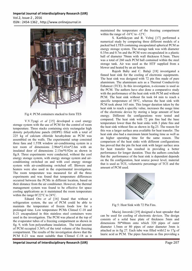
Rajesh Baby and C. Balaji [18] investigated a
finned heat sink for the cooling of electronic equipments.
The heat sink was designed with 72 pin fins made of pure
aluminium. The aluminium acts as a Thermal Conductivity
Enhancer (TCE). In this investigation, n-eicosane is used as
the PCM. The authors have also done a comparative study
with the performance of the heat sink with PCM and without
PCM. The heat sink without fin took 64 min to reach a
specific temperature of 58°C, whereas the heat sink with
PCM took about 165 min. This longer duration taken by the
heat sink to reach a specific value, increases the usage time
of the electronic device by storing a large amount of heat
energy. Different fin configurations were tested and
compared. The heat sink with 72 pin fins had the base
temperature lower than the heat sinks with 3 plate fins and
the heat sink without fins as shown in fig.23. The reason for
this was a larger surface area available for heat transfer. The
heat sink also had a maximum latent heating time as well as
an higher operating time for the same reason. The
comparison of the heat sinks with different configurations
has proved that the pin fin heat sink with larger surface area
for heat transfer has resulted in providing a better
performance for longer duration. Thus the authors conclude
that the performance of the heat sink is dependent depends
on the fin configuration, heat source power level, material
that is used as TCE, volumetric percentage of TCE and the
amount of PCM used.
Fig 5: Heat Sink with 72 Pin Fins.
Maciej Jaworski [19] designed a heat spreader that
can be used for cooling of electronic devices. The design
consists of a solid base plate of thickness 5mm and
dimensions 50*60mm onto which 320 pipes of outer
diameter 1.5mm or 80 pipes of outer diameter 3mm is
attached as in fig 27. Each tube was filled with12 to 17g of
lauric acid as PCM. The pipes functions as fins providing a
Imperial Journal of Interdisciplinary Research (IJIR) Vol.2, Issue-2 , 2016 ISSN : 2454-1362 , http://www.onlinejournal.in
Imperial Journal of Interdisciplinary Research (IJIR) Page 208
larger heat transfer surface and transfer of heat from the base
plate to the PCM. Presence of PCM prevents the
temperature of the microprocessor exceeding a certain value
which depends on the melting point of the PCM, thus
preventing the microprocessor from damages caused due to
excess heat. Hence the choice of the PCM is important. Also
the PCM increases the thermal capacity of the device. The
results of the investigation shows the effect of PCM used in
thermal performance of the heat spreader. The presence of
PCM in the pipes which gives larger heat transfer surface
area, specific air flow rate, keeps the temperature of the
microprocessor low which is lesser than 50°C. The different
configurations of the heat spreader reveal the difference in
their performance is due to the variations in the diameter of
the pipe, number of pipes. Heat spreader with larger pipe
diameters is better when compared to thin pipe diameters.
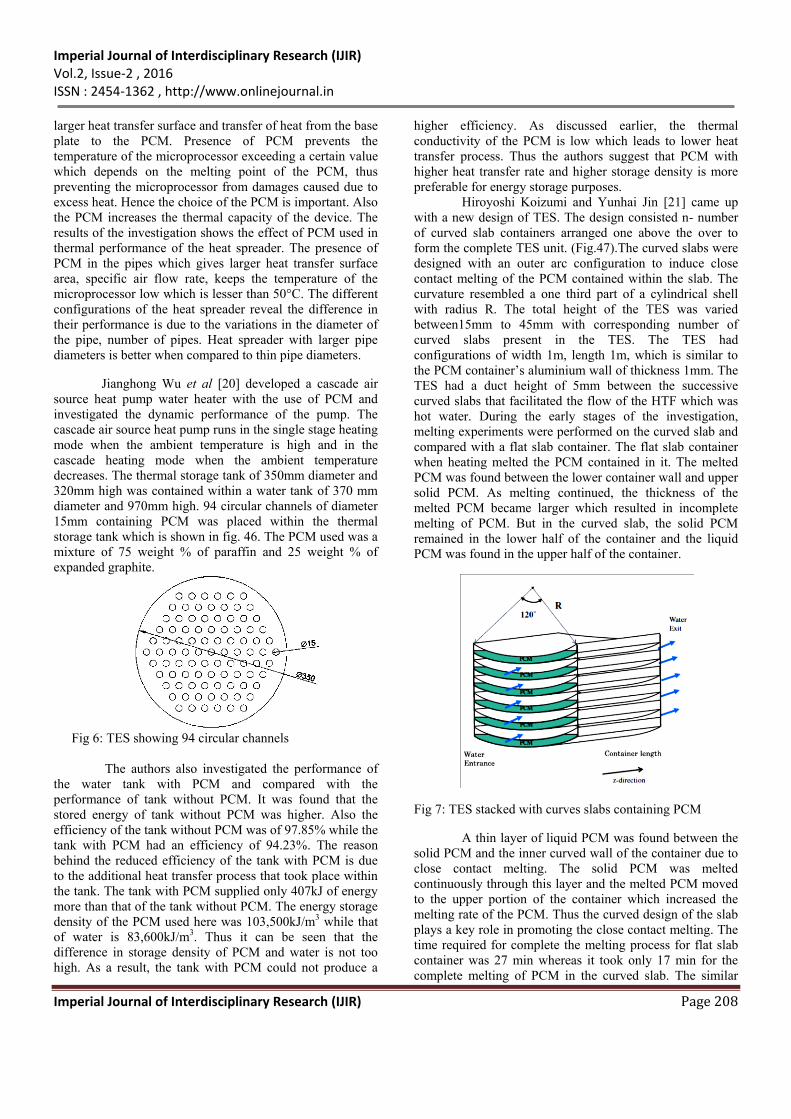
Jianghong Wu et al [20] developed a cascade air
source heat pump water heater with the use of PCM and
investigated the dynamic performance of the pump. The
cascade air source heat pump runs in the single stage heating
mode when the ambient temperature is high and in the
cascade heating mode when the ambient temperature
decreases. The thermal storage tank of 350mm diameter and
320mm high was contained within a water tank of 370 mm
diameter and 970mm high. 94 circular channels of diameter
15mm containing PCM was placed within the thermal
storage tank which is shown in fig. 46. The PCM used was a
mixture of 75 weight % of paraffin and 25 weight % of
expanded graphite.
Fig 6: TES showing 94 circular channels
The authors also investigated the performance of
the water tank with PCM and compared with the
performance of tank without PCM. It was found that the
stored energy of tank without PCM was higher. Also the
efficiency of the tank without PCM was of 97.85% while the
tank with PCM had an efficiency of 94.23%. The reason
behind the reduced efficiency of the tank with PCM is due
to the additional heat transfer process that took place within
the tank. The tank with PCM supplied only 407kJ of energy
more than that of the tank without PCM. The energy storage
density of the PCM used here was 103,500kJ/m3 while that
of water is 83,600kJ/m3. Thus it can be seen that the
difference in storage density of PCM and water is not too
high. As a result, the tank with PCM could not produce a
higher efficiency. As discussed earlier, the thermal
conductivity of the PCM is low which leads to lower heat
transfer process. Thus the authors suggest that PCM with
higher heat transfer rate and higher storage density is more
preferable for energy storage purposes.
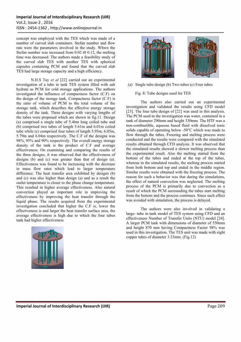
Hiroyoshi Koizumi and Yunhai Jin [21] came up
with a new design of TES. The design consisted n- number
of curved slab containers arranged one above the over to
form the complete TES unit. (Fig.47).The curved slabs were
designed with an outer arc configuration to induce close
contact melting of the PCM contained within the slab. The
curvature resembled a one third part of a cylindrical shell
with radius R. The total height of the TES was varied
between15mm to 45mm with corresponding number of
curved slabs present in the TES. The TES had
configurations of width 1m, length 1m, which is similar to
the PCM container’s aluminium wall of thickness 1mm. The
TES had a duct height of 5mm between the successive
curved slabs that facilitated the flow of the HTF which was
hot water. During the early stages of the investigation,
melting experiments were performed on the curved slab and
compared with a flat slab container. The flat slab container
when heating melted the PCM contained in it. The melted
PCM was found between the lower container wall and upper
solid PCM. As melting continued, the thickness of the
melted PCM became larger which resulted in incomplete
melting of PCM. But in the curved slab, the solid PCM
remained in the lower half of the container and the liquid
PCM was found in the upper half of the container.
Fig 7: TES stacked with curves slabs containing PCM
A thin layer of liquid PCM was found between the
solid PCM and the inner curved wall of the container due to
close contact melting. The solid PCM was melted
continuously through this layer and the melted PCM moved
to the upper portion of the container which increased the
melting rate of the PCM. Thus the curved design of the slab
plays a key role in promoting the close contact melting. The
time required for complete the melting process for flat slab
container was 27 min whereas it took only 17 min for the
complete melting of PCM in the curved slab. The similar
Imperial Journal of Interdisciplinary Research (IJIR) Vol.2, Issue-2 , 2016 ISSN : 2454-1362 , http://www.onlinejournal.in
Imperial Journal of Interdisciplinary Research (IJIR) Page 209
concept was employed with the TES which was made of a
number of curved slab containers. Stefan number and flow
rate were the parameters involved in the study. Whwn the
Stefan number was increased from 0.02 t0 0.12, the melting
time was decreased. The authors made a feasibility study of
the curved slab TES with another TES with spherical
capsules containing PCM and found that the curved slab
TES had large storage capacity and a high efficiency.
N.H.S Tay et al [22] carried out an experimental
investigation of a tube in tank TES system filled with salt
hydrate as PCM for cold storage applications. The authors
investigated the influence of compactness factor (C.F) on
the design of the storage tank. Compactness factor (C.F) is
the ratio of volume of PCM to the total volume of the
storage tank, which describes the effective energy storage
density of the tank. Three designs with varying lengths of
the tubes were proposed which are shown in fig.11. Design
(a) comprised a single tube of 5.46m long coiled tube and
(b) comprised two tubes of length 5.61m and 6.01m coiled
tube while (c) comprised four tubes of length 5.95m, 6.05m,
5.79m and 6.04m respectively. The C.F of the designs was
98%, 95% and 90% respectively. The overall energy storage
density of the tank is the product of C.F and average
effectiveness. On examining and comparing the results of
the three designs, it was observed that the effectiveness of
designs (b) and (c) was greater than that of design (a).
Effectiveness was found to be increasing with the decrease
in mass flow rates which lead to larger temperature
difference. The heat transfer area exhibited by designs (b)
and (c) was also higher than design (a) and as a result the
outlet temperature is closer to the phase change temperature.
This resulted in higher average effectiveness. Also natural
convection played an important role in improving the
effectiveness by improving the heat transfer through the
liquid phase. The results acquired from the experimental
investigation concluded that higher the C.F is, lower the
effectiveness is and larger the heat transfer surface area, the
average effectiveness is high due to which the four tubes
tank had higher effectiveness
(a) Single tube design (b) Two tubes (c) Four tubes
Fig. 8: Tube designs used for TES
The authors also carried out an experimental
investigation and validated the results using CFD model
[23]. The four tube design of [22] was used in this analysis.
The PCM used in the investigation was water, contained in a
tank of diameter 290mm and height 330mm. The HTF was a
non-combustible, aqueous based fluid with dissolved ionic
solids capable of operating below -50°C which was made to
flow through the tubes. Freezing and melting process were
conducted and the results were compared with the simulated
results obtained through CFD analysis. It was observed that
the simulated results showed a slower melting process than
the experimental result. Also the melting started from the
bottom of the tubes and ended at the top of the tubes,
whereas in the simulated results, the melting process started
from both bottom and top and ended in the middle region.
Similar results were obtained with the freezing process. The
reason for such a behavior was that during the simulations,
the effect of natural convection was neglected. The melting
process of the PCM is primarily due to convection as a
result of which the PCM surrounding the tubes start melting
from the bottom and the process continues. Since such effect
was avoided with simulation, the process is delayed.
The authors were also involved in validating a
large- tube in tank model of TES system using CFD and an
effectiveness Number of Transfer Units (NTU) model [24].
A larger PCM tank with dimensions of diameter of 550mm
and height 870 mm having Compactness Factor 98% was
used in this investigation. The TES unit was made with eight
copper tubes of diameter 3.33mm. (Fig.12)
Imperial Journal of Interdisciplinary Research (IJIR) Vol.2, Issue-2 , 2016 ISSN : 2454-1362 , http://www.onlinejournal.in
Imperial Journal of Interdisciplinary Research (IJIR) Page 210
Fig. 9: Tube in tank model for larger tanks
Heating/Charging and cooling/discharging
experiments were conducted and the results were validated
using the Effectiveness NTU approach and CFD. Comparing
the effectiveness acquired by experimental investigation,
NTU approach and CFD results, it was observed that the
experimental values were higher than the results of the other
two models. Similarly the experimental values of the
cooling process was greater than the effectiveness NTU
technique and CFD results due to the buoyancy effect that
was observed during the melting process. Also the phase
change duration for heating process was compared with the
effectiveness NTU and CFD technique. The CFD approach
had faster phase change duration than the experimental and
effectiveness NTU results since heat loss to the environment
occurred during the experimental investigation. But the
phase change duration for cooling experiments showed
delayed time in the CFD approach. The thermal resistance of
PCM during the charging process was found to account for
40 to 60% of the total resistance and during discharging it
was found of 70 – 80% of total resistance which was due to
the buoyancy effect. The authors concluded that the reason
for variation of the experimental results with CFD and
effectiveness NTU approach was due to the tube to tube
distance of 100mm in the design which reduced the heat
transfer and increased the resistance.
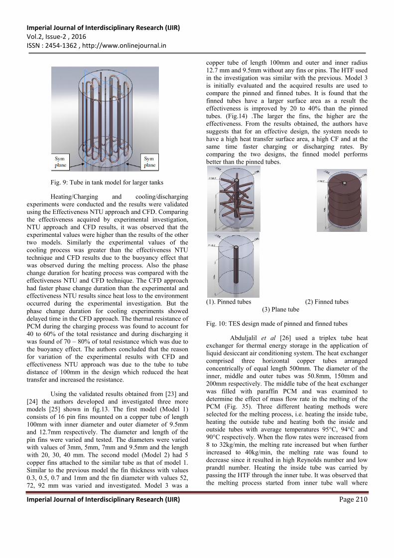
Using the validated results obtained from [23] and
[24] the authors developed and investigated three more
models [25] shown in fig.13. The first model (Model 1)
consists of 16 pin fins mounted on a copper tube of length
100mm with inner diameter and outer diameter of 9.5mm
and 12.7mm respectively. The diameter and length of the
pin fins were varied and tested. The diameters were varied
with values of 3mm, 5mm, 7mm and 9.5mm and the length
with 20, 30, 40 mm. The second model (Model 2) had 5
copper fins attached to the similar tube as that of model 1.
Similar to the previous model the fin thickness with values
0.3, 0.5, 0.7 and 1mm and the fin diameter with values 52,
72, 92 mm was varied and investigated. Model 3 was a
copper tube of length 100mm and outer and inner radius
12.7 mm and 9.5mm without any fins or pins. The HTF used
in the investigation was similar with the previous. Model 3
is initially evaluated and the acquired results are used to
compare the pinned and finned tubes. It is found that the
finned tubes have a larger surface area as a result the
effectiveness is improved by 20 to 40% than the pinned
tubes. (Fig.14) .The larger the fins, the higher are the
effectiveness. From the results obtained, the authors have
suggests that for an effective design, the system needs to
have a high heat transfer surface area, a high CF and at the
same time faster charging or discharging rates. By
comparing the two designs, the finned model performs
better than the pinned tubes.
(1). Pinned tubes (2) Finned tubes
(3) Plane tube
Fig. 10: TES design made of pinned and finned tubes
Abduljalil et al [26] used a triplex tube heat
exchanger for thermal energy storage in the application of
liquid desiccant air conditioning system. The heat exchanger
comprised three horizontal copper tubes arranged
concentrically of equal length 500mm. The diameter of the
inner, middle and outer tubes was 50.8mm, 150mm and
200mm respectively. The middle tube of the heat exchanger
was filled with paraffin PCM and was examined to
determine the effect of mass flow rate in the melting of the
PCM (Fig. 35). Three different heating methods were
selected for the melting process, i.e. heating the inside tube,
heating the outside tube and heating both the inside and
outside tubes with average temperatures 95°C, 94°C and
90°C respectively. When the flow rates were increased from
8 to 32kg/min, the melting rate increased but when further
increased to 40kg/min, the melting rate was found to
decrease since it resulted in high Reynolds number and low
prandtl number. Heating the inside tube was carried by
passing the HTF through the inner tube. It was observed that
the melting process started from inner tube wall where
Imperial Journal of Interdisciplinary Research (IJIR) Vol.2, Issue-2 , 2016 ISSN : 2454-1362 , http://www.onlinejournal.in
Imperial Journal of Interdisciplinary Research (IJIR) Page 211
conduction process came into act which resulted in a thin
layer of liquid formation. The liquid fraction increased with
time and natural convection and buoyancy forces came into
play which leads to heat transfer process in the upper part of
the storage and the melting process was improved. But it
was observed that the PCM was not completely melted since
heat transfer due to conduction and convection was not
enough. Similar process was observed with the other two
methods of heating but the heating started from outer tube
walls in second case and uniform temperature distribution
was observed in the last method of heating. It was also noted
that complete PCM melting was observed in the second and
third heating methods and the highest average PCM heating
temperature was observed in the third method of heating.
The reason behind this is the increase in the heat transfer
surface area that is noted in the second and third heating
methods. Temperature gradients along the axial, radial and
angular directions were measured and analyzed. No
variation in axial temperature was found with the three
methods of heating, but on observing the radial
temperatures, it was found that the heating inner tubes
resulted in high temperature closer to the inner tube wall and
while heating both tubes, inner tube wall and outer tube wall
temperature was found high since the flow rate was high in
the inner tube. The angular temperature measured was
greater at 90° for all three heating methods. This was
because of the natural convection and buoyancy forces.
Ehsan et al [27] designed a TES made of
corrugated copper panels. The TES was designed in such a
way that it had a high surface to volume ratio of 506.5 m-1
and high aspect ratio of 6.35. Six square corrugated copper
panels were soldered together to the centre at 60° forming
six corrugated fins as shown in fig.22. The square
corrugations were of sides 0.8 cm with center to center
distance of 1.6cm. There were totally six squares with three
on each side of the fins. The copper panels enclosed the
PCM for thermal energy storage and release and hence were
sealed tight to prevent any leakage of the PCM in liquid
phase.
Fig. 11: Corrugated TES
A total of 900 cm3 of octadecane was used as PCM
within the TES with 150 cm3 in each panel. The entire unit
was placed inside a clear plastic pipe with both ends closed
by perforated disks of diameter 16 cm at a distance of 15.2
cm from the TES. The experimental setup was in such a way
that hot water (HTF) is allowed to flow through the plastic
tube surrounding the TES unit in upward and downward
directions. Parameters that the authors considered for the
investigation were Reynolds number and Stefan number.
From the results, the heat transfer rate was found to be
increased when the HTF was made to flow upward through
the TES. During the charging process, the melting of the
PCM started from the bottom and buoyancy forces came
into play. With buoyancy forces affecting the heat transfer,
the melting time of the PCM was much reduced by 70%
when compared to the HTF flowing downward. Similarly
during the discharging process with HTF flowing upward,
the solidification of PCM started from bottom which
resulted in the discharging time three times faster than the
downward flow of HTF. Stefan number was considered as
one of the parameters for evaluating the TES system since it
defines the effect of HTF temperature on the performance of
the TES system. When higher values of Stefan number were
obtained, stratification effect was noted in the system. Two
flow rates were used and the axial and radial temperature
gradients were recorded. The observations resulted that there
was no effect in the axial temperature gradients due to
internal conduction and convection. Similarly the radial
temperature distribution was reduced with radial distance.
The experimental results obtained with the corrugated TES
were compared with a multi-tube system and was found that
the corrugated TES had better results. This was due to the
higher surface to volume ratio that was exhibited by the
corrugated TES design and the flow direction of the HTF.
11. CONCLUSION PCMs are widely used in cold storage applications
as well as heat storage applications. Cold storage
applications include frozen food preservation, refrigeration,
cooling of buildings, turbine inlet temperature. Similarly
heat storage applications include hot water tanks, air
heating, waste heat recovery. Usage of PCM integrated TES
system in such applications leads to improved performance,
efficiency, and as well as the energy storage capacity of the
total system. But PCMs have very low thermal conductivity,
which is a major drawback of the PCMs. Hence the
Thermal Energy Storage system or the PCM tank must be
wisely chosen such that improved performance of the
system is obtained. Performance improvement can be
obtained through proper consideration of the material with
high thermal conductivity, design with higher heat transfer
areas and several parameters like input temperature,
dimensions, C.F, flow rate. When A TES system designed
effectively, promotes the melting/charging and
freezing/discharging of the PCM faster. Avoiding sharp
corners of TES systems promotes complete melting of the
Imperial Journal of Interdisciplinary Research (IJIR) Vol.2, Issue-2 , 2016 ISSN : 2454-1362 , http://www.onlinejournal.in
Imperial Journal of Interdisciplinary Research (IJIR) Page 212
PCM contained in the system. Use of pins and fins provide a
larger heat transfer surface area thereby promoting faster
melting and solidifying rates. Conduction process followed
by Convection promotes the melting of PCM as energy is
absorbed, while conduction process alone dominates the
freezing process as the stored energy is released. Hence it is
important that the design of the TES is in such a way that
the melting and freezing process are improved and a proper
PCM with required properties are selected for an effective
performance of the thermal storage system.
REFERENCES 1 Ahmet Kurklu, Aziz O zmerzi, Sefai Bilgin,
“Thermal performance of a water-phase change
material solar collector,” Renewable Energy 26
(2002) 391–399
2 Jian-You Long, Dong-Sheng Zhu, “Numerical and
experimental study on heat pump water heater with
PCM for thermal storage,” Energy and Buildings
40 (2008) 666–672
3 Mohammad Ameri, Seyed Hossein Hejazi,
Kourosh Montaser, “Performance and economic of
the thermal energy storage systems to enhance the
peaking capacity of the gas turbines,” Applied
Thermal Engineering 25 (2005) 241–251
4 Jinjia Wei, Yasuo Kawaguchi, Satoshi Hirano,
Hiromi Takeuchi, “ Study on a PCM heat storage
system for rapid heat supply,” Applied Thermal
Engineering 25 (2005) 2903–2920
5 Haiting Cui a.b, Xiugan Yuan a, Xinbin Hou,
“Thermal performance analysis for a heat receiver
using multiple phase change materials,” Applied
Thermal Engineering 23 (2003) 2353–2361
6 Ella Talmatsky, Abraham Kribus, “ PCM storage
for solar DHW: An unfulfilled promise?,” Solar
Energy 82 (2008) 861-869
7 T. Kousksou, P. Bruel, G. Cherreau, V. Leoussoff,
T. El Rhafiki, “ PCM storage for solar DHW: From
an unfulfilled promise to a real benefit,” Solar
Energy 85 (2011) 2033–2040
8 Manuel Ibanez, Luisa F. Cabeza, Cristian Sole,
Joan Roca, Miquel Nogues, “Modelization of a
water tank including a PCM module,” Applied
Thermal Engineering 26 (2006) 1328-1333
9 Muhsin Mazmana, Luisa F. Cabeza, Harald
Mehling, Miquel Nogues, Hunay Evliya, Halime
O. Paksoy, “ Utilization of phase change materials
in solar domestic hot water systems,” Renewable
Energy 34 (2009) 1639–1643
10 S.O. Enibe, “Thermal analysis of a natural
circulation solar air heater with phase change
material energy storage,” Renewable Energy 28
(2003) 2269–2299
11 Frederic Kuznik, Joseph Virgone, Jean Noel,
“Optimization of a phase change material
wallboard for building use,” Applied Thermal
Engineering 28 (2008) 1291–1298
12 Dariusz Heim, Joe A. Clarke, “Numerical
modelling and thermal simulation of PCM–gypsum
composites with ESP-r,” Energy and Buildings 36
(2004) 795–805
13 Lv Shilei, Zhu Neng, Feng Guohui, “Impact of
phase change wall room on indoor thermal
environment in winter,” Energy and Buildings 38
(2006) 18–24
14 P.W. Griffiths, P.C. Eames, “Performance of
chilled ceiling panels using phase change material
slurries as the heat transport medium,” Applied
Thermal Engineering 27 (2007) 1756–1760
15 Guobing Zhou, Yinping Zhang, Qunli Zhang,
Kunping Lin, Hongfa Di, “Performance of a hybrid
heating system with thermal storage using shape-
stabilized phase-change material plates,” Applied
Energy 84 (2007) 1068–1077
16 Chengbin Zhang, Yongping Chen, Liangyu Wu,
Mingheng Shi, “Thermal response of brick wall
filled with phase change materials (PCM) under
fluctuating outdoor temperatures,” Energy and
Buildings 43 (2011) 3514–3520
17 Ahmet Kocaa, Hakan F. Oztopb, Tansel Koyunc,
Yasin Varol, “Energy and exergy analysis of a
latent heat storage system with phase change
material for a solar collector,” Renewable Energy
33 (2008) 567–574
18 K. Azzouz, D. Leducq, D.Gobin, “Performance
enhancement of house hold refrigerator by addition
of latent heat storage,” International Journal of
Refrigeration 31 (2008) 892-901
19 Benjamin Gin, Mohammed M. Farid, “ The use of
PCM panels to improve storage condition of frozen
food,” Journal of Food Engineering 100 (2010)
372-376
20 F.L. Tan, C.P. Tso, “Cooling of mobile electronic
devices using phase change materials,” Applied
Thermal Engineering 24 (2004) 159-169
21 Yue-Tzu Yang, Yi-Hsien Wang, “Numerical
simulation of three-dimensional transient cooling
application on a portable electronic device using
phase change material,” International Journal of
Thermal Sciences 51 (2012) 155-162
22 S.M. Vakilaltojjar, W. Saman, “Analysis and
modelling of a phase change storage system for air
conditioning applications,” Applied Thermal
Engineering 21 (2001) 249-263
23 K.A.R. Ismail, J.R. Henriquez, “Thermally
effective windows with moving phase change
material curtains,” Applied Thermal Engineering
21 (2001) 1909-1923
24 Xu Xu, Yinping Zhang, Kunping Lin, Hongfa Di,
Rui Yang, “Modeling and simulation on the
thermal performance of shape-stabilized phase
change material floor used in passive solar
Imperial Journal of Interdisciplinary Research (IJIR) Vol.2, Issue-2 , 2016 ISSN : 2454-1362 , http://www.onlinejournal.in
Imperial Journal of Interdisciplinary Research (IJIR) Page 213
buildings,” Energy and Buildings 37 (2005) 1084–
1091
25 E. Halawa, W. Saman, “ Thermal performance
analysis of a phase change thermal storage unit for
space heating,” Renewable Energy 36 (2011) 259-
264
26 Isabel Cerona, Javier Neila, Mohamed Khayet,
“Experimental tile with phase change materials
(PCM) for building use,” Energy and Buildings 43
(2011) 1869–1874
27 V.V. Tyagi, D. Buddhi, Richa Kothari, S.K. Tyagi,
“Phase change material (PCM) based thermal
management system for cool energy storage
application in building: An experimental study,”
Energy and Buildings 51 (2012) 248–254
28 Eduard Oro, Laia Miro, Mohammed M. Farid,
Luisa F. Cabeza, “Thermal analysis of a low
temperature storage unit using phase change
materials without refrigeration system,”
International Journal of Refrigeration 35 (2012)
1709-1714
29 T. Kousksou, J.P. Bedecarrats, J.P. Dumas, A.
Mimet, “Dynamic modeling of the storage of an
encapsulated ice tank,” Applied Thermal
Engineering 25 (2005) 1534–1548
30 Zouhair Ait Hammou, Marcel Lacroix, “ A new
PCM storage system for managing simultaneously
solar and electric energy,” Energy and Buildings 38
(2006) 258-265
31 S. Karthikeyan, R. Velraj, “Numerical investigation
of packed bed storage unit filled with PCM
encapsulated spherical containers - A comparison
between various mathematical models,”
International Journal of Thermal Sciences 60
(2012) 153-160
32 Esam M. Alawadhi, “Temperature regulator unit
for fluid flow in a channel using phase change
material,” Applied Thermal Engineering 25 (2005)
435–449
33 Huseyin Benli, Aydin Durmus. “Performance
analysis of a latent heat storage system with phase
change material for a new designed solar collectors
in greenhouse heating,” Solar Energy 83 (2009)
2109-2119
34 N.H.S. Tay, M. Belusko, F. Bruno, “Experimental
investigation of tubes in a phase change thermal
energy storage system,” Applied Energy 90 (2012)
288–297
35 N.H.S. Tay, F. Bruno, M. Belusko, “Experimental
validation of a CFD model for tubes in a phase
change thermal energy storage system,”
International Journal of Heat and Mass Transfer 55
(2012) 574–585
36 N.H.S. Tay, F. Bruno, M. Belusko, “ Experimental
validation of a CFD and an e-NTU model for a
large tube-in-tank PCM system,” International
Journal of Heat and Mass Transfer 55 (2012) 5931–
5940
37 N.H.S. Tay, F. Bruno, M. Belusko, “Comparison of
pinned and finned tubes in a phase change thermal
energy storage system using CFD,” Applied
Energy 104 (2013) 79–86
38 Jundika C. Kurnia, Agus P. Sasmito, Sachin V.
Jangam, Arun S. Mujumdar, “Improved design for
heat transfer performance of a novel phase change
material (PCM) thermal energy storage (TES)”,
Applied Thermal Engineering 50 (2013) 896-907
39 A.de Gracia, E. Oró, M.M. Farid, L.F. Cabeza , “
Thermal analysis of including phase change
material in a domestic hot water cylinder,” Applied
Thermal Engineering 31 (2011) 3938-3945
40 M.J. Kabbara, N.Ben Abdallah, “Experimental
investigation on phase change material based
thermal energy storage unit,” Procedia Computer
Science 19 (2013) 694 – 701
41 Uros Stritih, “An experimental study of enhanced
heat transfer in rectangular PCM thermal storage,”
International Journal of Heat and Mass Transfer 47
(2004) 2841–2847
42 Albert Castell, Cristian Sole, Marc Medrano, Joan
Roca, Luisa F. Cabeza, Daniel Garcia, “Natural
convection heat transfer coefficients in phase
change material(PCM) modules with external
vertical fins,” Applied thermal engineering 28
(2008) 1676-1686
43 Wei-Biao Ye, Dong-Sheng Zhu, Nan Wang,
“Numerical simulation on phase-change thermal
storage/release in a plate-fin unit," Applied
Thermal Engineering 31 (2011) 3871-3884
44 A.H. Mosaffaa, F. Talati, H. Basirat Tabrizi, M.A.
Rosen, “ Analytical modeling of PCM
solidification in a shell and tube finned thermal
storage for air conditioning systems,” Energy and
Buildings 49 (2012) 356–361
45 Ehsan Mohseni Languri, Clifford O. Aigbotsua,
Jorge L. Alvarado, “Latent thermal energy storage
system using phase change material in corrugated
enclosures,” Applied Thermal Engineering 50
(2013) 1008-1014
46 Xiang-Qi Wang, Arun S. Mujumdar, Christopher
Yap, “Effect of orientation for phase change
material (PCM)-based heat sinks for transient
thermal management of electric components,”
International Communications in Heat and Mass
Transfer 34 (2007) 801–808
47 Xiang-Qi Wang, Christopher Yap, Arun S.
Mujumdar, “A parametric study of phase change
material (PCM)-based heat sinks,” International
Journal of Thermal Sciences 47 (2008) 1055–1068
48 Ravi Kandasamy, Xiang-Qi Wang, Arun S.
Mujumdar, “ Transient cooling of electronics using
Imperial Journal of Interdisciplinary Research (IJIR) Vol.2, Issue-2 , 2016 ISSN : 2454-1362 , http://www.onlinejournal.in
Imperial Journal of Interdisciplinary Research (IJIR) Page 214
phase change material (PCM)-based heat sinks,”
Applied Thermal Engineering 28 (2008) 1047–
1057
49 G. Setoh, F.L. Tan, S.C. Fok, “Experimental
studies on the use of a phase change material for
cooling mobile phones,” International
Communications in Heat and Mass Transfer 37
(2010) 1403–1410
50 Rajesh Baby, C. Balaji, “Experimental
investigations on phase change material based
finned heat sinks for electronic equipment
cooling,” International Journal of Heat and Mass
Transfer 55 (2012) 1642–1649
51 S.C. Fok, W. Shen, F.L. Tan, “ Cooling of portable
hand-held electronic devices using phase change
materials in finned heat sinks,” International
Journal of Thermal Sciences 49 (2010) 109–117
52 Maciej Jaworski, “Thermal performance of heat
spreader for electronics cooling with incorporated
phase change material,” Applied Thermal
Engineering 35 (2012) 212-219
53 S.F. Hosseinizadeh, F.L. Tan, S.M. Moosania, “
Experimental and numerical studies on
performance of PCM-based heat sink with different
configurations of internal fins,” Applied Thermal
Engineering 31 (2011) 3827-3838
54 S.B. Riffat, S.A. Omer, Xiaoli Ma, “A novel
thermoelectric refrigeration system employing heat
pipes and a phase change material: an experimental
investigation,” Renewable Energy 23 (2001) 313–
323
55 S.A Omer, S.B.Riffat, Xiaoli Ma, “Experimental
investigation of a thermoelectric refrigeration
system employing a phase change material
integrated with thermal diode (thermosyphons),”
Applied Thermal Engineering 21 (2001) 1265-1271
56 Francis Agyenim, Neil Hewitt, “The development
of a finned phase change material (PCM) storage
system to take advantage of off-peak electricity
tariff for improvement in cost of heat pump
operation,” Energy and Buildings 42 (2010) 1552–
1560
57 Nourouddin Sharifi, Theodore L. Bergman, Amir
Faghri, “Enhancement of PCM melting in
enclosures with horizontally-finned internal
surfaces,” International Journal of Heat and Mass
Transfer 54 (2011) 4182–4192
58 Vincenc Butala, Uros Stritih, “Experimental
investigation of PCM cold storage,” Energy and
Buildings 41 (2009) 354–359
59 Christopher W. Robak, Theodore L. Bergman,
Amir Faghri, “ Enhancement of latent heat energy
storage using embedded heat pipes,” International
Journal of Heat and Mass Transfer 54 (2011) 3476–
3484
60 Fuqiao Wang, Graeme Maidment, John Missenden,
Robert Tozer, “The novel use of phase change
materials in refrigeration plant. Part 1:
Experimental investigation,” Applied Thermal
Engineering 27 (2007) 2893–2901
61 M. Medrano, M.O. Yilmaz, M. Nogués, I.
Martorell, Joan Roca, Luisa F. Cabeza,
“Experimental evaluation of commercial heat
exchangers for use as PCM thermal storage
systems,” Applied Energy 86 (2009) 2047–2055
62 Abduljalil A. Al-Abidi, Sohif Mat, K. Sopian, M.Y.
Sulaiman, Abdulrahman. Th. Mohammad,
“Experimental study of PCM melting in triplex
tube thermal energy storage for liquid desiccant air
conditioning system,” Energy and Buildings 60
(2013) 270–279
63 Mehmet Akif Ezan, Muhammet Ozdogan, Aytunç
Erek, “ Experimental study on charging and
discharging periods of water in a latent heat storage
unit,” International Journal of Thermal Sciences 50
(2011) 2205-2219
64 M.J. Huang, P.C. Eames, S. McCormack, P.
Griffiths, N.J. Hewitt, “ Microencapsulated phase
change slurries for thermal energy storage in a
residential solar energy system,” Renewable
Energy 36 (2011) 2932-2939
65 V. Pandiyarajan, M. Chinna Pandian, E. Malan, R.
Velraj, R.V. Seeniraj, “Experimental investigation
on heat recovery from diesel engine exhaust using
finned shell and tube heat exchanger and thermal
storage system,” Applied Energy 88 (2011) 77–87
66 Francis Agyenim, Philip Eames, Mervyn Smyth,
“Heat transfer enhancement in medium temperature
thermal energy storage system using a multitube
heat transfer array,” Renewable Energy 35 (2010)
198–207
67 M.J. Hosseini, A.A. Ranjbar, K. Sedighi, M.
Rahimi, “ A combined experimental and
computational study on the melting behavior of a
medium temperature phase change storage material
inside shell and tube heat exchanger,” International
Communications in Heat and Mass Transfer 39
(2012) 1416–1424
68 F.L. Tan a,*, S.C. Fok, “ Cooling of helmet with
phase change material,” Applied Thermal
Engineering 26 (2006) 2067–2072
69 Colas Hasse, Manuel Grenet, André
Bontemps,Rémy Dendievel, Hébert Sallée,
“Realization, test and modelling of honeycomb
wallboards containing a Phase Change Material,”
Energy and Buildings 43 (2011) 232–238
70 Ying-Che Weng, Hung-Pin Cho, Chih-Chung
Chang, Sih-Li Chen, “ Heat pipe with PCM for
electronic cooling,” Applied Energy 88 (2011)
1825–1833

Imperial Journal of Interdisciplinary Research (IJIR) Vol.2, Issue-2 , 2016 ISSN : 2454-1362 , http://www.onlinejournal.in
Imperial Journal of Interdisciplinary Research (IJIR) Page 215
71 K. Nithyanandam, R. Pitchumani, “Analysis and
optimization of a latent thermal energy storage
system with embedded heat pipes,” International
Journal of Heat and Mass Transfer 54 (2011) 4596-
4610
72 Jianghong Wua, Zhaoguang Yang, Qinghao Wub,
Yujuan Zhu, “ Transient behavior and dynamic
performance of cascade heat pump water heater
with thermal storage system,” Applied Energy 91
(2012) 187–196
73 Hiroyoshi Koizumi, Yunhai Jin, “Performance
enhancement of a latent heat thermal energy
storage system using curved-slab containers,”
Applied Thermal Engineering 37 (2012) 145-153
74 X. Duan, G.F. Naterer, “Heat transfer in phase
change materials for thermal management of
electric vehicle battery modules,” International
Journal of Heat and Mass Transfer 53 (2010) 5176–
5182
75 Kamal El Omari, Tarik Kousksou, Yves Le Guer,
“Impact of shape of container on natural
convection and melting inside enclosures used for
passive cooling of electronic devices,” Applied
Thermal Engineering 31 (2011) 3022-3035


![Development of sunlight-driven eutectic phase change material … · 2018. 11. 5. · tectic mixtures/expanded graphite PCM composite [21] were pre- pared and their thermal properties](https://cdn.vdocuments.us/doc/165x107/60d8c0d46523cf5c9576ab20/development-of-sunlight-driven-eutectic-phase-change-material-2018-11-5-tectic.jpg)