REVIEW OF NASA SUPERCRITICAL AIRFOILS
Richard T. Whitcomb National Aeronautics and Space Administration
Langley Research Center Hampton, Virginia
Abstract
NASA supercr i t ical a i r f o i l s a re characterized by a substant ial ly reduced
curvature of the mid-chord region of the upper surface together with increased
camber near the t r a i l i n g edge. The basic aerodynamic phenomena associated
with the a i r f o i l s and representative wind tunnel r e s u l t s a r e discussed. The
r e su l t s indicate t h a t & e drag r i s e Mach numbers fo r NASA supercr i t ical a i r f o i l s
a re 0.1 higher than fo r comparable NACA 6-series a i r f o i l s . A recent analytic
method f o r predicting the aerodynamic character is t ics of supercr i t ical a i r f o i l s
i s described. The f l i g h t demonstration programs of three applications of
supercr i t ical a i r f o i l s u t i l i z ing the F-8, T-2C and F-111 a s t e s t beds a r e
summarized.
I. Introduction
It is well known t h a t the subsonic cruise speeds of high performance
a i r c r a f t a r e l imited by the onset of the transonic drag r i s e . The use of wing
sweepback delays t h i s onset. However, fo r pract ical amounts of sweepback
(approximately 35') t he onset s t i l l occurs well below the speed of sound
( ~ a c h numbers between 0.80 and 0.85). One method f o r increasing the cruise
speed fur ther is the use of a i r f o i l shapes which delay the drag r i s e .
The first a i r f o i l s developed i n the U. S. A. t o delay the drag r i s e
were the NACA 1 ser ies airfoils!' These a i r f o i l s , designed t o increase the
c r i t i c a l Mach number, t h a t i s , the Mach number at which supersonic flow first
develops loca l ly on the a i r f o i l , have drag r i s e Mach numbers significantly

higher than the ewlier mACA four digit secriea airfoils. Howeyer the
low-speed, high-lifi characteristics of these airfoils are signi#icwtly
poorer than for the earlier drfofls . As a ~ e m t they are uaed only on
high speed propeller blades. The RACA 6-series airfoils aZso proflde
increased c r i t i c d Mach nrmobers with result- jsqpro~ementa in the drag
rise characteristics as compared with those for the h-digit series!' They
result in a md.1 degradation in the low speed c ~ a c t e r i a t i c s . These
airfoils, or their derivatives, were used on most of the first generation
of aubsonic Jet airdrerf% deaigned in the U, 5. A.
The first airfoils designed specifically t o delay drrtg piee by j~~profing
the supercriticd. flow above the upper surface were the l f p e ~ " ai;rPoils Of
Pearcj!' They proyide an isentropic reoompreeaion of the supersonic P l m
ahead of the shock wave. These airfofls result in approximately a .Wd to
.03 d e l a y In the drag ~ f s e with a small degradation of the low speed c W a c t e r -
i s t i c s compared with NACA 6 series airfoils. These airfoils or the* deri:yetiyes
were used on the second generation of subsonic j e t aircref't designed in the U. S. A.
The airfoils to be described herein also are aesigned to improve the
supercriticd flow. They we designed to allow the shock waye to move to
the rear part of the airfoil at the design condition. As a reault they proyide
considerably higher drag rise Mach numbers than prefious airfoils. In the
first work on this approach it was assumed that a slot was requfred to
stabilize the upper surface bounihy layer!4) Later it m a found that vlth
the proper upper surface pressure distribution the boundary layer could be
maintained attached up to the design lkch number without the slot. The
results of the first work on the integral or unslotted airfoil was g i e n
limited distribution in 1967 in a Confidentfal b l e y Working Paper. This

paper has been declass i f ied recent ly and forms t h e bas i s f o r much of t he
discussion included herein. It should be noted, however, t h a t t h e extensive
experimental r e s u l t s obtained since 1967 on refinements and applications
of the NASA supercr i t i ca l a i r f o i l s a r e s t i l l c l a s s i f i ed ,
11. Description and Flow Phenomena a t Design Condition
Description
The evolution of t h e general shape of t he NASA supercr i t i ca l a i r f o i l
i s shown i n f igure 1. I n all cases t he shape i s characterized by substant ia l ly
reduced curvature of t h e middle region of t h e upper surface with a l a rge amount
of camber near t he t r a i l i n g edge. Also the leading edge radius is larger than
previously used and the t r a i l i n g edge closure angle i s very small, It w i l l be
noted t h a t t he or ig ina l in tegra l a i r f o i l had a very t h i n t r a i l i n g edge which
l ed t o s t ruc tura l problems, Therefore t he t r a i l i n g edge was thickened a s
shown a t t he bottom of f igure 1. This change not only improved the s t ruc ture
but a l so the high speed aerodynamic charac te r i s t ics a t k%@ing conditions
with very l i t t l e increase i n t he basic subsonic drag level . The advantages
of thickened t r a i l i n g edges fo r transonic a i r f o i l s i s discussed i n reference
5. The a i r f o i l s used f o r all t h e f l i g h t demonstration programs t o be
described have included t h i s thickened t r a i l i n g edge.
Flow Phenomena a t Desian Condition
A comparison of t h e supercr i t i ca l flow phenomena f o r t he NASA supercr i t i ca l
a i r f o i l and an NACA 6 se r i e s a i r f o i l a t the c ru ise l i f t coeff ic ient i s presented
i n f igure 2. For t h e NACA 6 s e r i e s a i r f o i l , a s shown a t t h e top of t he f igure ,
t h e supersonic flow accelerated t o t he shock wave located near t he mid chord,
causing a strong, extensive shock wave. This wave i s followed immediately
by a subsonic pressure recovery t o t he t r a i l i n g edge. The energy l o s s i n t h e
shock causes some drag increase. Howeyer, the dominant problem i s severe
boundary separation caused by the large, steep t o t a l streamwise pressure
increase, This separation, of course, proiiuces t h e well known abrupt drag
r i s e , buffeting, and s t a b i l i t y problems.
The surface pressure dis t r ibut ion and flow f i e l d shown a t t he bottom
of figure 2 a re representative of those obtainea f o r NASA supercr i t ical a i r f o i l s .
The upper surface pressure and r e l a t e d ~ e l o c i t y dis t r ibut ions a re characterized
by a shock location s ignif icant ly a f t of the midchord, an approximately unifom
supersonic velocity from about the 5% chord s ta t ion t o the shock, a plateau
in the pressure dis t r ibut ion rearward of the shock, a re la t ive ly steep subsonic
pressure recwery on the extreme rearward regionland a t r a i l i n g edge pressure
near ambient. The lower surface has roughly constant negative presaure
coefficients corresponding t o subcri t ical .velocities over the forward region
and a rapid increase i n pressure rearward of the midchord t o a substantially
posit ive pressure forward of the t r a i l i n g edge.
The elimination of t h e flow acceleration on the upper surface ahead of
the shock wave, which r e s u l t s primarily from the reduced curvature of the
midchord region, obviously provides a reduction of t h e Mach number ahead of
the shock fo r a given l i f t coefficient with a resul t ing decrease of the shock
strength, The strength and extent of the shock a t t he design condition can be
reauced below tha t for the pressure dis t r ibut ion shown by shaping the air-
f o i l t o provide a gradual deceleration of the supersonic flow from near the
leadfng edge t o the shock wave. (31, c4" C61 H~wever, as w i l l be discussed ! . . 1. - - a
l a t e r , such a shapemay have an increased drag a t lower Mach numbers. Extensive
experiments indicate tha t the shape associated with t h e design point dis t r ibut ion
shown provides acceptable arag values over the Mach number and lift coefficient
range. Theory and experiments indicate tha t with the pressure dis t r ibut ion
shown and at the s l igh t ly negative angle of a t tack required t o obtain the
design l i f t coefficient t h e ve r t i ca l extent of the supersonic f i e l d decreases
ahead of the shock wave as shown on the l e f t i n f igure 2. This effect i s
s i m i l a r t o that for a i r f o i l s designed specif ical ly t o minimize the extent of
the shock at the design point although i n t h i s case the effect i s somewhat
smaller. The flow f i e l d calculations of reference 6 i l l u s t r a t e
the origin of t h i s effect .
Thepateau i n the pressure dis t r ibut ion rearward of the shock wave
allows a reenergization of the boundary layer by mixing a f t e r it moves through
the severe adverse pressure gradient of the shock and before it moves through
the pressure gradient near the t r a i l i n g edge, A s a resul t , the boundary layer
canmove through a greater t o t a l pressure r i s e without separating. The
importance of t h i s effect w i l l be shown by the experimental data t o be
presented l a t e r . The near-ambient pressure at the t r a i l i n g edge, which
re su l t s from the s m a l l included angle of the t r a i l i n g edge, reduces t o a
minimum the t o t a l pressure r i s e the upper surface boundary layer must t raverse
and thus minimizes the tendancy toward separation.
The maintainence of subcr i t ica l flow over the forward region of the
lower surface eliminates the poss ib i l i ty of a shock wave on tha t surface. The
pressure r i s e of a possible shock wave superimposed on the pronounced pressure
r i s e on the rear portion of t h i s surface would grea t ly increase thetendency,..
for-the-bo~ndCrrg'~layer t e ~ s e p a r a t e . The substant ial ly posi t ive pressure on
the r e a r par t of the lower surface, associated with t h e surface concavity of
t h i s region, allows a s ignif icant reduction i n t h e negative pressure coefficients
and related ve loc i t ies required on the upper surface t o obtain a given l i f t .
This,of course,allows an increase i n the drag r i s e Mach number. The pressure
increase rearward of the midchord i s defined by the Stratford c r i t e r i a . (7 1
The relatively large leading edge radii: of the NASA supercritical
airfoils allow simultaneous reductions of the curvatures of the midchord
regions of both the upper and lower surfaces with resulting rebctions of
the induced velocities. However, experiments indicate that the use.of
relative radii larger than that listed in Table I results in increases of
the low speed drag.
111. Experiments and Aerodynamic Characteristics
Experiments
The Langley 8-Foot Transonic Pressure Tunnel in which the NASA supercritical
airfoils have been developed has solid side walls and thus can be used without
modification to obtain two-dimensional results. A model of an intergral
Cunslotted) supercritical airfoil is shown installed in the tunnel in figure
3. The lift and pitching moment characteristics are obtained by surface
pressure measurements while the.drag.is:derived: from wake surveys. These
measurements also provide substantial information on the flow phenomena in-
volved. Additional information on the flow phenomena is obtained by surface
oil flow studies. (8) The test Reynolds number at Mach numbers near 0.80 is 6 7 x 10 which is substantially less than the flight values for most airplanes.
To simulate full scale Reynolds numbers at least at and near the design
condition the technique described in reference 9 is utilized.
Aerodynamic Characteristics
To provide a general indication of the aerodynamic characteristics of
NASA supercritical airfoils at and off the design condition the experimental
results for the 11%-thick representative airfoil shape defined by Table I
will be presented. The variation of drag with Mach number for the design
lift coefficient of 0.6 is shown in figure 4. Similar variations for an
NACA 64-212 airfoil (lo) and a slotted supercritical airfoil(-4) are shown for
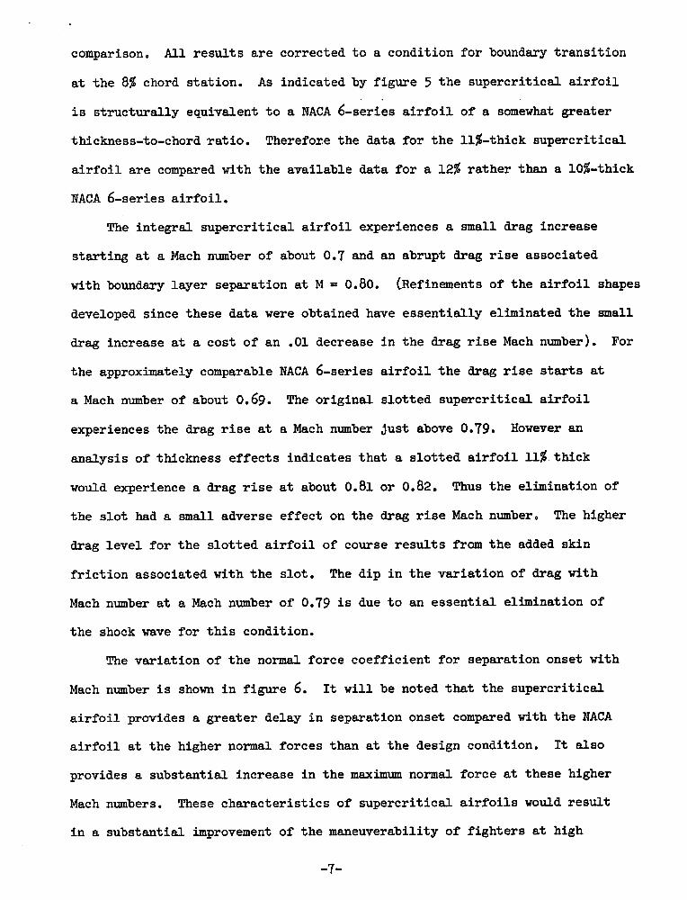
comparison. A l l r e s u l t s a r e corrected t o a condition f o r boundary t r ans i t i on
a t t h e 8% chord s ta t ion. A s indicated by f igure 5 t h e supercr i t i ca l a i r f o i l
i s s t ruc tura l ly equivalent t o a NACA 6-series a i r f o i l of a somewhat greater
thickness-to-chord ~ a t i o . Therefore the data f o r t h e 11%-thick supercr i t i ca l
a i r f o i l a r e compared with the available data f o r a 12% ra the r than a 10%-thick
NACA 6-series a i r f o i l ,
The in tegra l supercr i t i ca l a i r f o i l experiences a small drag increase
s ta r t ing a t a Mach number of about 0.7 and an abrupt drag r i s e associated
with bound- layer separation at M = 0.80. (~ef inements of t h e a i r f o i l shapes
developed since these da ta were obtained have essen t ia l ly eliminated t h e small
drag increase a t a cost of an .01 decrease i n t h e drag r i s e Mach number). For
the approximately comparable NACA 6-series a i r f o i l t h e drag r i s e starts a t
a Mach number of about 0.69. The or ig ina l s lo t t ed supercr i t i ca l a i r f o i l
experiences the drag r i s e a t a Mach number jus t above 0.79, However an
analysis of thickness e f fec t s indicates t h a t a s l o t t e d a i r f o i l 11% thick
would experience a drag r i s e a t about 0.81 o r 0.82. Thus t h e elimination of
t he s l o t had a s m a l l aclverse e f fec t on the drag rise Mach number, The higher
drag l eve l f o r t he s lo t t ed a i r f o i l of course r e s u l t s from t h e added skin
f r i c t i o n associated with t h e s lo t . The d ip i n t h e va r i a t i on of drag with
Mach number a t a Mach number of 0.79 i s due t o an e s sen t i a l elimination of
the shock wave f o r t h i s condition.
The var ia t ion of t h e normal force coeff ic ient f o r separation onset with
Mach number i s shown i n f i gu re 6. It w i l l be noted t h a t t h e supercr i t i ca l
a i r f o i l provides a greater delay i n separation onset compared with t he NACA
a i r f o i l a t t h e higher normal forces than a t t he design condition, It a l so
provides a substant ia l increase i n t he maximum normal force at these higher
Mach numbers. These charac te r i s t ics of supercr i t i ca l a i r f o i l s would r e su l t
i n a substant ia l improvement of t he maneuverability of f i gh te r s a t high
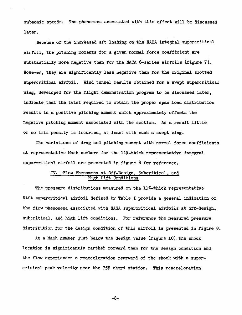
subsonic speeds, The phenomena associated with this effect w i l l be discussed
l a t e r . Because of the increased aft loading on t h e NASA in tegra l supercyitical
a i r f o i l , the pitching moments for a given normal force coefffcient w e
substantially more negative than fo r the NACA 6-series a i r f o i l s (f'igure 71.
However, they a re s ignif icant ly l e s s negative than f o r t h e or iginal s lo t ted
supercr i t ical a i r f o i l . Wind tunnel r e su l t s obtained f o r a swept supercr i t ical
wing, developed f o r the f l i g h t demonstration program t o be discussed later,
indicate tha t the twist required t o obtain the proper span load dis t r ibut ion
r e su l t s i n a posit ive pitching moment which approximately of fse ts the
negative pitching moment associated with the section. A s a r e su l t l i t t l e
or no trim penalty i s incurred, a t l e a s t with such a swept wing.
The variations of drag and pitchingmoment with normal force coefficients
a t representative Mach numbers f o r the 11%-thick representatiye integral
supercr i t ical a i r f o i l a r e presented i n figure 8 f o r reference.
IV. 'Flow Phenomena a t Off-Desian, Subcrit ical , and High L i f t Conditions
The pressure dis t r ibut ions measured on the 11%-thick ~epresen ta t iye
NASA supercr i t ical a i r f o i l defined by Table I provide a general indication of
the flow phenomena associated with NASA supercr i t ica l a i r f o i l s a t off-design,
subcri t ical , and high l i f t conditions. For reference the measured pressure
dis t r ibut ion f o r the design condition of t h i s a i r f o i l i s presented i n f igure 9,
A t a'Mach number jus t below the design value (figure 1 0 ) , t h e shock
location i s s ignif icant ly fa r ther forward than for the design condition and
the flow experiences a reacceleration rearward of t h e shock with a super-
c r i t i c a l peak velocity near the 75% chord s tat ion. This reacceleration

causes a substantially greater and steeper pressure increqse t o the t r e i l i n g
edge as compared with the design condition. T h i s steeper Tepoyery r e s u l t s
i n a small adverse effect on the t r a i l i n g edge pressure recoyexy and drgg.
For unslotted a i r f o i l s designed t o achieye a shockless design condition (4
the reacceleration veloci ty can be suf'ficiently great t o cause a second
") The t o t a l pressure ,rise of t h i s second shock and rearward shock wwe.
the immediately following subsonic pressure recovery may cause sCgnificant
b o u n a ~ y layer separation near the t r a i l i n g edge.
A t subcri t ical Mach numbers (figure 111 the pressure dis t r ibut ion has
a significant peak near the leading edge. The presence of t h i s peak r e s u l t s
i n a small drag increment f o r subcri t ical and s l igh t ly supercrit ic@ conditi.ons.
If an a i r f o i l is shaped t o provide a decellerating supersonic yelocity
dis t r ibut ion on the upper surface at the design condition as discussed e a r l i e r
t h i s subcri t ical peak i s substantially greater than t h a t shown with-a resu l t ing
increase i n the drag f o r the subcr i t ica l and s l igh t ly supercr i t icel eonditions.
The pressure d is t r ibut ion shown i n f igure 12 i s tha t measured a t t he
highMach number corner of the .variation of normal force f o r separation onset
with Mach number shown previously i n figure 6. The shock wave associated
with an upstream Mach number of 1.4, causes a very la rge adverse pressure
graaient. However, t he t r a i l i n g edge pressure recovery and a surface o i l
flow study indicate tha t the boundary layer does not completely sepaxate. The
bulge i n the pressure dis t r ibut ion a f t of the shock wave and the surface o i l
studysinaZciteiamery large separation bubble under the shock which reat taches
near the .75 chord s tat ion. For previous a i r f o i l shapes, such as the NACA
6-series, t he presence of a shock wave associated with an upstream Mach number
of 1.4 causes very severe boundary layer separation. (12 The key t o the

greater s t a b i l i t y of the boundary layer $07 the supercr i t ica l a i H o i l is the
plateau i n the pressure dis t r iPut ipn a f t of the shock waye deqcyihed egrl ier .
For previous a i r f ~ i l s t h e subsonic pressure Tecovery h e a i a t e l y aownstream
of the shock wave opposes boundary layer ~eat tachment . With the plateau on
the supercr i t ical a i r f o i l t h i s adverse effect i s eliminated. It i s of
in te res t t ha t unpublished bounaft~y layer surveys indicate t h a t t he boundary
layer separation developlent under the shock fo r supercr i t ica l a i r f o i l s i s
quite similar t o tha t on a f l a t plate. 0-3 1
'Y. Thick Supercrit ical Air fo i l s
In the prwious discussion the increase i n drag r i s e 'Mach number f o r a
given a i r f o i l thickness-to-chord r a t i o provided by the NASA s u p e r c ~ i t i c a l
a i r f o i l has been emphasizes. However, t he same approach can be us& t o
provide a substantial increase i n section thickness-ratio f o r the same
drag r i s e Mach number. The f i r s t thick supercr i t ica l a i r f o i l was developed
by W. Palmer of the Columbus, Ohio Division of North American-Rockwell
(figure 13). This 17%-thick a i r f o i l has the same drag r i s e Mach number as
a 12$-thick NACA 6-series a i r f o i l a t the same l i f t coefficient.
YI, Theoretical Analysis
Considerable progress has been made during the last three years i n
providing theoret ical methods fo r the design and analysis of two-aimensional
a i r f o i l s at supercr i t ical Mach numbers. No attempt w i l l be made t o cover
a l l t h i s work, instead the method being used a t Langley i n a continuing
ef for t on supercr i t ica l a i r f o i l s w i l l be described.
The i n i t i a l comparisons of theoret ical ly derived pressure dis t r ibut ions
on NASA supercr i t ical a i ~ f o i l s with experimental r e s u l t s indicated 'very poor
agreement. The differences a re associatea with the development of the
boundary layers on these a i r f o i l s , i l l u s t r a t e a by f igure 14.

'The steep pressure r i s e near the t r a i l i n g edge of t h e upper surface causes
t h e boundary layer t o thicken s ignif icant ly . On the lower surface -- -- - - - - -- - - - - -
t he pressure ~ i s e from about the .5 t o t he .9 chords results i n a substant ia l
thickening of t h e boundary layer i n t he cusp while t h e rapid pressure decrease
near t he t r a i l i n g ed@;e causes a pronounced thinning of t h e boundary layer. Each - . - -- - -
of these e f f ec t s contributes t o a substant ia l reduction of t h e e f fec t ive a f t
camber of t he a i r f o i l . It was concluded that f o r NASA supercr i t i ca l a i r f o i l s
any analytic method must include t h e e f f ec t of t he boundary layer.
'Recently an analyt ic method which includes t h e e f f ec t of t h e boundary
layer has been developed a t Langley. ( I4 ) This i t e r a t i v e procedure i s based
on the method of Korn and Garabedian ( I5 ) f o r analyzing t h e external super-
c r i t i c a l f i e ld , which implements a transonic f ini te-difference scheme defined
(16) A similar method was a lso developed by Jameson. by Murman. (17) The
coordinate system, shown i n f igure 15, was suggested by S e l l s C18) and consis ts
of mapping t h e i n t e r i o r of t h e u n i t c i r c l e conformally onto t h e ex te r ior of
t he a i r f o i l with t he point at i n f i n i t y corresponding t o t h e origin. These
flow f i e l d computations a r e made f o r a i r f o i l shapes modified by t h e calculated
displacement thicknesses of t he upper and lower surface boundary layers. The
displacement thicknesses a r e determined by the method of Bradshaw. '19) since
the boundary layer calculations a r e not applicable near t h e t r a i l i n g edge an
empirical correction i s applied f o r t h i s region.
The e f f ec t of including the boundary layer on ana ly t ica l predicted
pressure d i s t r ibu t ions f o r an NASA s u p e r ~ r i t i c a l a i r f o i l i s i l l u s t r a t e d i n
f igure 16. These comparisons a r e fo r l i f t coeff ic ients substant ia l ly greater
than the design value. A t a subcr i t i ca l Mach number, including t h e e f f ec t of
t h e boundary layer causes a moderate change i n t he predicted l i f t . However,
a t a supercr i t i ca l Mach number including the e f f ec t of t h e boundmy layer
r e s u l t s i n substant ia l changes of t h e posit ion of t h e shock wave and the l i f t .
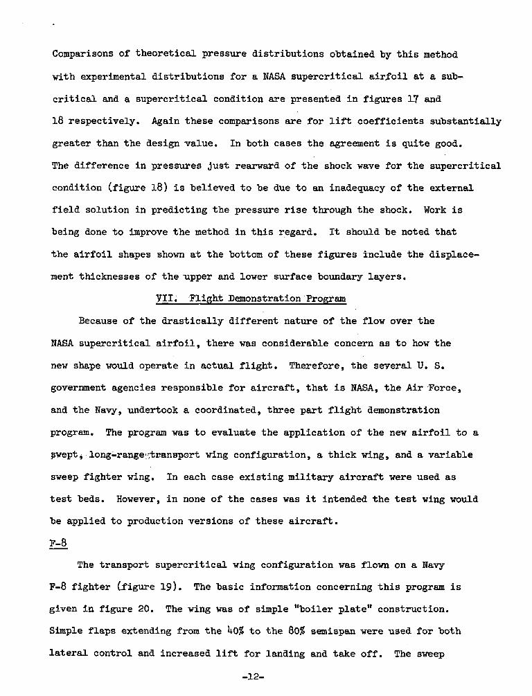
Comparisons of theoret ical pressure dis t r ibut ions obtained by t h i s method
with experimental dis t r ibut ions for a NASA supercr i t ica l a i r f o i l a t a sub-
c r i t i c a l and a supercr i t ical condition a re presented i n figures 17 and
18 respectively. Again these comparisons a re f o r l i f t coeff ic ients substantially
greater than the design value. In both cases the agreement i s quite good.
The difference i n pressures Just rearward of the shock wwe fo r the supercr i t ical
condition (figure 18) i s believed t o be due t o an inadequacy of the external
f i e l d solution i n predicting the pressure r i s e through the shock. Work is
being done t o improve t h e method i n t h i s regard. It should be noted tha t
t he a i r f o i l shapes shown a t the bottom of these f igures include the displace-
ment thicknesses of the upper and lower surface boundary layers.
Y I I . Flight Demonstration Program
Because of the d ras t i ca l ly different nature of the flow over the
NASA supercr i t ical a i r f o i l , there was considerable concern as t o how the
new shape would operate i n actual f l i gh t . Therefore, the several U. S.
government agencies responsible f o r a i r c ra f t , t ha t i s NASA, the A i r Force,
and the Navy, undertook a coordinated, three part f l i g h t demonstration
program. The program was t o evaluate the application of the new a i r f o i l t o a
pwept, long-range~;trranwport wing configuration, a th ick wing, and a variable
sweep f ighter wing. In each case existing mi l i ta ry a i r c r a f t were used a s
t e s t beds. However, i n none of the cases was it intended the t e s t wing would
be applied t o production versions of these a i r c ra f t .
F-8 - The transport supercr i t ical wing configuration was flown on a Navy
F-8 f ighter e i g u r e 19). The basic information concerning t h i s program is
given i n f igure 20. The wing was of simple "boiler plate" construction.
Simple f laps extending from the 408 t o the 80% semispan were used fo r both
l a t e r a l control and increased l i f t fo r lanaing and take off . The sweep
-12-

of t h e midchord was 40'. The a i r f o i l shape outboard approximately t he 40%
semispan s ta t ion was the same as t h a t developed during t h e previously
described two-dimensional investigations. However t h e a i r f o i l shapes f o r
the inboard section yeyes - s i ihstant ia l lyia lBe~eat .to.-acoountr'f OT. Oheilaqge
three-dimensional e f f ec t s i n this region at the near sonic cruiseMach
number. The forward extension of t he leading edge near t h e fuselage a l so
improved the near-sonic three-dimensional flow on t h i s inboard region. The
wing had substant ia l t w i s t .
T-2C - The th ick supercr i t i ca l a i r f o i l was flown on a Navy T-2C t ra iner . A
comparison of a i r c r a f t without and with t he th ick section i s shown i n
f igure 21, The basic information concerning t h i s program i s given 5n
f igure 22. The section shape was obtainea by droo9ing t h e f l a p and ai leron
and then adding balsa wood and f iberg lass t o t h e or ig ina l wing structure.
The a i r f o i l shape was t h e same along the e n t i r e span. Some of t h e r e s u l t s
from t h i s program a r e present i n reference 20.
F-111
The var iable sweep supercr i t i ca l f i gh t e r wing i s being flown on a U. S,
. A i r Force 3'-111 (figure 23). The basic information concerning this program
i s given i n f igure 24. Only t h e var iable sweep panels have been changed
from t h e or ig ina l configuration. The wing panels have been designed f o r
minimum weight and a re equipped with s ing le s lo t t ed t r a i l i n g edge f l a p s
and Kreuger leading edge f laps . The a i r f o i l shapes a r e s imilar t o those
developed two-dimensionally. The panels have subs tan t ia l t w i s t .
a. ' Applications
Following the wind tunnel development of t h e near sonic t ransport wing
configuration usea f o r t h e F-8 f l i g h t demonstration, a complete near-sonic
(20) wee transport configuration, incorporating t h i s wing w a s defined,
U. S. aircraft manufacturers, Boeing, General Dynamics, and Lockheed, under
contract to W A evaluated actual transport aesigns based on thfs configura-
tion. (21 An artist's concept of the General Dynamic's design is shown in
figure 25.
More recently a number of U. S. aircraft manufacturers h m e initiated
new military and commercial airplane designs incorporating NASA supercritical
airfoils. It should be noted that for transport aircraft the principal
interest at present is in using the airfoils to obtain reduced fuel consumption
rather than to obtain increased speed. For a given cruise speed the ai~foils
allow a reduction in wing sweep and/or an increase in section thickness ratio
which permit an increase in wing aspect ratio or a reduction in wing weight.
These changes of course provide a reduction in fuel consumption.
IX. Concluding Bemarks
Over the past ten years extensive wina tunnel investigations of two-
dimensional sections and three-dimensional applications of NASA supercritical
airfoils have been conducted, In addition, two flight demonstration programs
have been completed and another initiated. The results of this research
indicate that the use of these airfoils can successfully provide substantial
improvements of the speed, fuel consumption, or maneuverability of most
aircraft intended for operation at high subsonic speeds. Also, the analytic
methods now becoming available can greatly aid in the design of new operational
aircraft incorporating these airfoils.

1. Stack, John; Tests of Ai r fo i l s Designed t o Delay t h e C q p r e s s i b i l i t y
Burble. NACA !lW 9-76, 1944.
Abbott, Ira He; von Boenhoff, Albert E.; and St ivers , Louis S., Jr.:
Summary of Ai r fo i l Data. NACA 'Report No. 824, 1945
Pearcey, H. H.: The Aerodynamic Design of Section Shapes f o r Swept
Wings. Advances i n Aeronautical Sciences, 701. 3, p. 27.7, Pergamon
Press, 1962.
Whitcomb, Xichard T.; and C l a ~ k , Larry'R,: An Ai r fo i l Shape f o r Eff ic ient
Fl ight a t Supercr i t ical Mach Numbers. NASA TM X-1109, 1965 . Holder, D. W.: The Transonic Tlow Past Two-Dimensional Aerofoils. J. Boy.
Aeronaut. SOC, , vol . 68, no, 644, Aug. 1964, pp. 501-516.
Bauer, F.; Garabeaian, P.; and Korn, D.: Supercr i t ical Wing Sections.
Springer-Verlag, 1972.
Stratford, B, S.: The Prediction of Separation of t h e Turbulent Boundary
Layer, Jo Fluid Mech., vol. 5, pp. 1-16, 1959,
Loving, Donald L.; and Katzoff, S.: The Fluorescent-Oil Film Method and
Other Techniques for Boundary-Layer 'Flow Visualization. NASA Memo
3-17-59L9 1959-
Blackwell, James A., Jr.: Preliminary Study of Effects of 'Reynolds Number
and Boundary-Layer Transit ion Location on Shock-Inaucea Separation.
NASA Tn D-5003, 1969.
Van Dyke, Bfilton D.; ana Wibbert, Gordon A.: High-Speed Aerodynamic
Characterist ics of 12 Thin NACA 6-series Airfoi ls . NACANFI A5F27,
1945.
11. Kacprzynski, J. J.; Ohman, Lo H.; Garabedian, P. 3.; and Korn,D. G;
Analysis of t h e Flgw Past a Shockless L i f t ing A i r fo i l i n Design
and Off-Design Conditions. NRC 'Report LR-554, 19111.
12. Daley, Bernard N.; and Dick, 'Richard S.: Effect of Thickness, Camber,
and Thickness Dis t r ibu t ion on Ai r fo i l Character is t ics a t Mach Numbers
Up t o 1.0. NACA TN 3'607,'1958.
13. Seddon, J.: The Flow Produced by Interact ion of a Turbulent Boundary
Layer With a Normal Shock Wave of Strength Suf f ic ien t t o Cause
Separation. 'R & M No. 3502, Br i t i sh A.B.C., March 1960.
14. Bavitz, Paul C. : An Analysis Method f o r Two-Dimensional Transonic
Y ~ S C O U S F ~ O W , NASA@-% . , 1974.
15. Garabedian, P, 3.; ana Korn, D. G.: Analysis of Transonic Ai r fo i l s .
Comm. on Pure and Applied Math., vol. 24, pp. 841-851, 19111.
16. Murman, E a r l 1 M. ; and Cole, Ju l ian Do : Calculation of Plane Steady
Transonic 'Flows. AIAA J., ~ o l . 9, NO. 1, pp. 114-131, 1971.
17. Jameson, A.: Transonic Flow Calculations f o r A i r fo i l s ana Bodies of
Revolution. GTumman Aero. Corp. 3ep. 390-71-1, 1971.
18. Se l l s , C. C. L.: Plane Subcr i t i ca l Flow Past a L i f t ing Aerofoil,
Proc . Roy Soc . (London), vol. 308A, pp. 377-401, 1968.
19. Bradshaw, P.; Fe r r i s s , D. H.; and Atwell, No P.: Calculation of
Boundary-Layer Development Using t h e Turbulent Energy Equation.
J. ,Fluid Mech., vol. 28, pa r t 3, pp. 593-616, 1967.
20. Ayers, T. G.: Supercr i t i ca l Aerodynamics, Astronautics and Aeronautics,
pp , 32-36, August 1972.
21. Braslow, A. L.; and A l f o ~ d , W. J,: Advanced Subsonic Transport Technology.
Astronautics and Aeronautics, pp. 26-31, August 1972.

TABLE I. - COORDINATES FOR AN 11%-THICK REPRESEWTATIVE NASA SUPERCRITICAL AIRFOIL
4
I
x/c
0.0075 -0125 .0250 0 0375 a 0500 a 0750 .lo00 .1250 .I500 01750 *2000 .2500 .3000 .3500 .4000 .4500 .5000 5500
0 5750 .6000 -6250 .6500 6750
.7000 07250 a7500 7750
.8ooo
.8250
.8500 08750 .goo0 09250 0 9500 9750
1.0000
Upper
0.0176 .0215 .0276 .0316 0 0347 .0394 .0428 .oh55 .0476 .oh93 -0507 .o528 .0540 0547
a 0550 .0548 .0543 -0533 0 0527 0519
-0511 .0501 .0489 .0476 .0460 .0442 .oh22 .0398 -0370 . 0337 .0300 o 0255 .0204 -0144 -0074 -, 0008
P z / c
Lower
-0.0176 - -0216 -. 0281 -. 0324 -. 0358 - .0408 -. 0444 -, 0472 -. 0493 -0 0510 - 0522 -. 0540 -. 0548 -. 0549 -. 0541 -. 0524 -. 0497 -.0455 - -0426 - -0389 - .0342 - .0282 - 0215 -. 0149 -. OOgO - 0036 . 0012 . .0053
.0088
.0114
.0132
.0138
.0131
.0106
.0060 - .0013
\
L. E. radius: 0.0245~


