Revealing the Unmonitored Risks in your Rotating Equipment
An Opportunity for Innovation
A recent review of high-speed rotating machinery events revealed a concerning number of
torsional vibration failures within the last two decades. Three examples are summarized to
highlight the variety of issues and failure modes.
The steam turbine of a Pressurized Water Reactor nuclear reactor experiences an anomalous
event and the machine is manually tripped due to excessive radial vibration in the low-
pressure section. The investigation concludes that a blade was ejected from a low-pressure
stage and that detailed inspections have revealed additional cracked blades in several
stages. The root cause is determined to be excessive torsional vibration triggered by
torsional excitation in the train. A later industry study of 65 Pressurized Water Reactors
shows that approximately 10% of the plants had similar events involving turbine blade
failures which were suspected to be caused by the same torsional vibration phenomenon.
(Ref 1)
A pipeline gas transmission train experiences three coupling failures over a short duration of
time. The investigation reveals that the installation of several pieces of equipment has
shifted the expected torsional vibration natural frequencies. As a result, the operating speed
of the train exactly matches a torsional vibration resonance. (Ref 2)
During the startup of a train, comprising of a synchronous motor driving a speed increasing
gear box connected to a centrifugal compressor, the motor speed drops several times. After
12 seconds of operation, the high-speed coupler fails with component ejection. The damaged
coupler spacer shows the characteristic 45o angle indicating torsional failure. It is determined
that faulty wiring of the motor caused current fluctuations that excited the torsional natural
frequency. (Ref 3)
Unexpected and unmonitored torsional vibration is at the heart of these recent case studies
resulting in sudden failures, costly downtown and potential safety risk. This short paper will
examine the origins of torsional vibration and a few case histories to drive an understanding
of the unmonitored risk existing at many industrial sites.
Torsional Vibration- What Is It?
All rotating equipment power trains found at industrial sites have vibration, usually caused by
mechanical unbalance of the rotating system, shaft misalignment, or weakness in the bearing
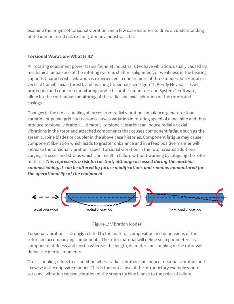
support. Characteristic vibration is experienced in one or more of three modes: horizontal or
vertical (radial), axial (thrust), and twisting (torsional), see Figure 1. Bently Nevada’s asset
protection and condition monitoring products; probes, monitors and System 1 software,
allow for the continuous monitoring of the radial and axial vibration on the rotors and
casings.
Changes in the cross coupling of forces from radial vibration, unbalance, generator load
variation or power grid fluctuations cause a variation in rotating speed of a machine and thus
produce torsional vibration. Ultimately, torsional vibration can induce radial or axial
vibrations in the rotor and attached components that causes component fatigue such as the
steam turbine blades or coupler in the above case histories. Component fatigue may cause
component liberation which leads to greater unbalance and in a feed positive manner will
increase the torsional vibration issues. Torsional vibration in the rotor creates additional
varying stresses and strains which can result in failure without warning by fatiguing the rotor
material. This represents a risk factor that, although assessed during the machine
commissioning, it can be altered by future modifications and remains unmonitored for
the operational life of the equipment.
Figure 1: Vibration Modes
Torsional vibration is strongly related to the material composition and dimensions of the
rotor and accompanying components. The rotor material will define such parameters as
component stiffness and inertia whereas the length, diameter and coupling of the rotor will
define the inertial moments.
Cross coupling refers to a condition where radial vibration can induce torsional vibration and
likewise in the opposite manner. This is the root cause of the introductory example where
torsional vibration caused vibration of the steam turbine blades to the point of failure.
Why does torsional vibration matter? All rotating equipment is expected to experience variations in speed and thus are subjected
to torsional vibration. Effective accurate measurement of torsional vibration allows an
operator to evaluate several issues including torsional natural frequencies, dynamic stresses,
torsional modes shape, component fatigue and load vibration. Torsional vibration, in some
cases, can be deduced by case accelerometers but is best detected and monitored directly
from the rotor. Data from direct measurements are essential to compare with dynamic
model simulations. Monitoring torsional vibration as a regular part of preventative
maintenance will reduce maintenance costs and may be useful in decreasing machine
operating margins.
Sophisticated torsional rotor dynamics may allow one to verify three important parameters,
that of the torsional natural frequency, the associated torsional mode shapes and the rotor
response, sometimes referred to as the “personality” of the rotor. These calculations allow
the operator to set separation margins between the desire operating speeds and torsional
resonances and thus avoid possible damage and failures. Many operators desire a fourth
parameter, that of a “rain fall” counter, meaning the combination of frequency of vibration,
amplitude of response and stress response calculations that predict the end of life or
remaining life of various rotor components.
Methodologies and Technologies for evaluating Torsional Vibration
Presently, torsional vibration is the most difficult of the three vibrations to measure and
monitor. There is no commercially viable large application non-contacting continuous
torsional vibration sensing and monitoring solution available. Several offered techniques
involving contacting the rotor, such as zebra tape or strain gauges, or adding a component
such as a stub shaft (strain gauges) or toothed gear wheel with a magnetic pickup, into the
rotor train. These products remain intrusive, expensive and are often noncontinuous. (Ref 4-
5)
Most commonly used for the investigation and analysis of torsional vibration, is temporary
sensors installation onto the rotor such as optical encoders based on Zebra tape or strain
gauges. The sensors are installed during a shutdown and operated over short power startups
and excursions to gather data before removal and restarting the train.
For example, Bently Nevada Machinery Diagnostic Services (Ref 6) monitored a Gas Turbine
Generator set at two locations using toothed timing speed wheels and optical zebra tape.
The Bently Nevada MDS tool set was employed to evaluate the gathered data and tooth
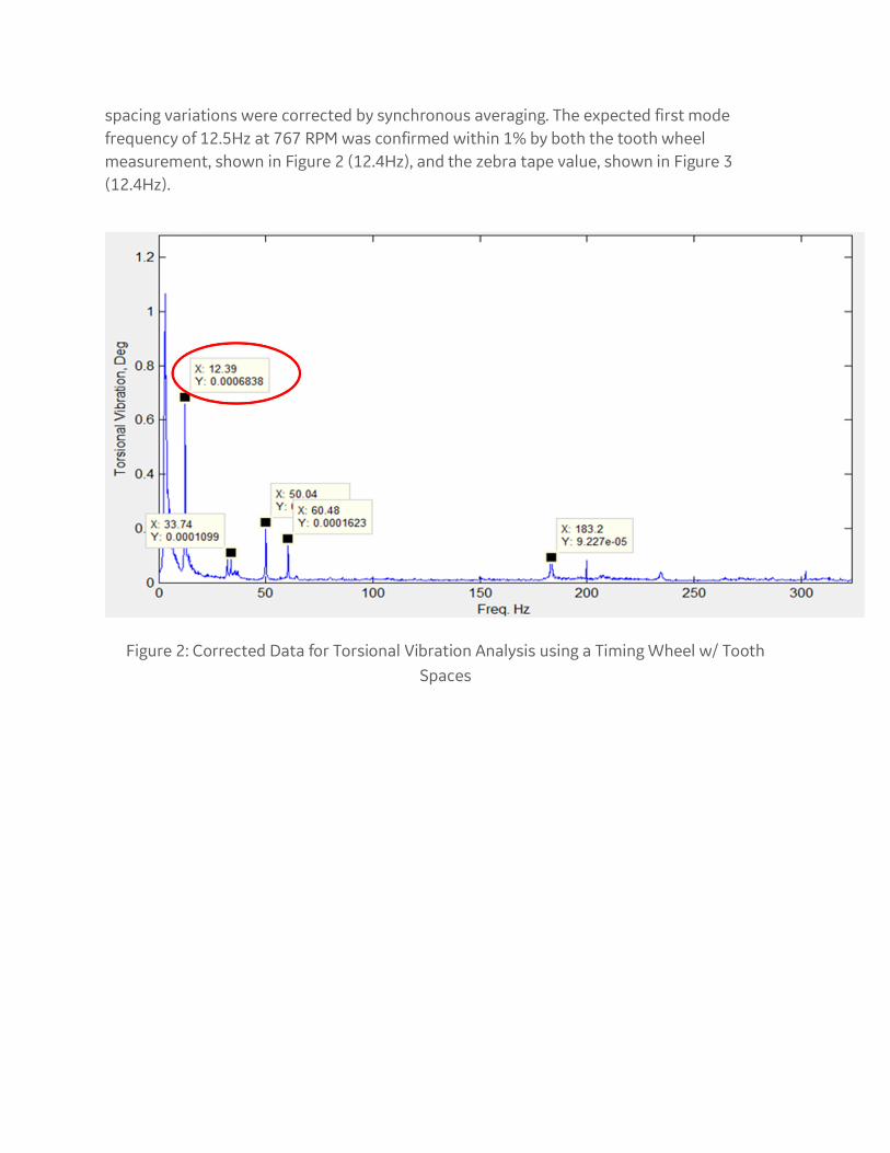
spacing variations were corrected by synchronous averaging. The expected first mode
frequency of 12.5Hz at 767 RPM was confirmed within 1% by both the tooth wheel
measurement, shown in Figure 2 (12.4Hz), and the zebra tape value, shown in Figure 3
(12.4Hz).
Figure 2: Corrected Data for Torsional Vibration Analysis using a Timing Wheel w/ Tooth
Spaces

Figure 3: Torsional Vibration Analysis from Zebra Tape Encoders
In some circumstances, Bently Nevada’s proximity probes and monitors have been used to infer torsional vibration measurements. For example, at one site, rotor displacement amplitudes on high-speed gearboxes were observed to enter alarm and occasionally a trip condition at low loads. This occurred on three identical aeroderivative compression trains. Bently Nevada Machinery Diagnostic Services (Ref 7) used available historical low load conditions data to create spectral plots which revealed fluctuations in direct amplitudes to be attributable to a 12.7 Hz frequency component, as shown in Figure 4. This frequency did not correspond with any rotational speed or harmonic/subharmonic. A torsional vibration model Campbell diagram, however, indicated a first torsional natural frequency at 769 CPM corresponding to 12.8Hz. Using this information, it was determined that gas heaters, firing at 20ms burst to preheat the fuel gas, caused power instability. The control system was then modified to eliminate the first torsional natural frequency excitation.
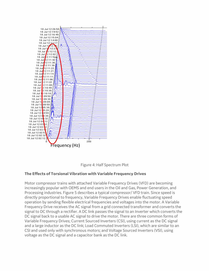
Figure 4: Half Spectrum Plot
The Effects of Torsional Vibration with Variable Frequency Drives Motor compressor trains with attached Variable Frequency Drives (VFD) are becoming increasingly popular with OEMS and end users in the Oil and Gas, Power Generation, and Processing industries. Figure 5 describes a typical compressor/ VFD train. Since speed is directly proportional to frequency, Variable Frequency Drives enable fluctuating speed operation by sending flexible electrical frequencies and voltages into the motor. A Variable Frequency Drive receives the AC signal from a grid connected transformer and converts the signal to DC through a rectifier. A DC link passes the signal to an Inverter which converts the DC signal back to a usable AC signal to drive the motor. There are three common forms of Variable Frequency Drives; Current Sourced Inverters (CSI), using current as the DC signal and a large inductor as the DC link; Load Commuted Inverters (LSI), which are similar to an CSI and used only with synchronous motors; and Voltage Sourced Inverters (VSI), using voltage as the DC signal and a capacitor bank as the DC link.
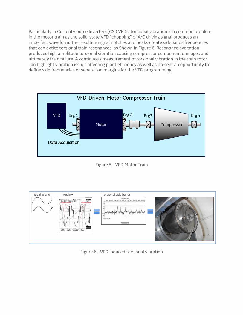
Particularly in Current-source Inverters (CSI) VFDs, torsional vibration is a common problem in the motor train as the solid-state VFD “chopping” of A/C driving signal produces an imperfect waveform. The resulting signal notches and peaks create sidebands frequencies that can excite torsional train resonances, as Shown in Figure 6. Resonance excitation produces high amplitude torsional vibration causing compressor component damages and ultimately train failure. A continuous measurement of torsional vibration in the train rotor can highlight vibration issues affecting plant efficiency as well as present an opportunity to define skip frequencies or separation margins for the VFD programming.
Figure 5 - VFD Motor Train
Figure 6 - VFD induced torsional vibration

Conclusion
Effective accurate measurement of torsional vibration allows an operator to evaluate several
issues including torsional natural frequencies, dynamic stresses, torsional modes shape,
component fatigue and load vibration. Torsional vibration, in some situations, can be
deduced by case accelerometers but is best detected and monitored directly from the rotor.
Presently, torsional vibration is the most difficult of the three vibrations to measure and
monitor. As no industrially hardened non-contacting continuous torsional vibration
monitoring system is currently widely available, investigation and analysis are usually
achieved by using other direct and indirect methods. All plant operators whether at power
generator or Oil and Gas locations are at risk of rotating machinery damage or unplanned
plant outages due to failures by not continuously monitoring torsional vibration. This is a
widespread unplanned maintenance time-bomb and provides an unparalleled opportunity
for innovation.
References:
Ref 1: https://www.nrc.gov/docs/ML0319/ML031900050.pdf
Ref 2: Preventing Unexpected Train Torsional Oscillations, J. Corcoran et al., 39th Turbo Pump
Symposium, Houston, 2010,
Ref 3: Coupling Failure due to a Motor Fault, C. McClinton et al., 43th Turbo Pump Symposium,
2014, Houston,
Ref 4: Fundamentals of Rotating machinery Diagnostics, D. Bently, 2002
Ref 5:
file:///C:/Users/204012219/Downloads/Torsional%20Vibration%20White%20Paper%20(4).p
df
Ref 6: BN Case History

About Bently Nevada
Bently Nevada product line has been synonymous with machinery protection and condition
monitoring for more than 60 years. Our network of global experts is dedicated to helping our
customers solve some of their toughest challenges in the oil and gas and power generation
industries. From refineries and petrochemical plants to hydroelectric facilities and wind
farms, Bently Nevada Asset Condition Monitoring offers trusted and proven vibration
monitoring equipment and a comprehensive services portfolio to help improve the reliability
and performance of production assets like turbines, compressors, motors, generators, and
everything in between.
Behind every suite of great products is a team of great people, and the Bently Nevada team is
one of the most experienced in the industry. That experience translates into high-quality,
flexible and scalable solutions coupled with a dedicated services team focused on providing
proactive, consistent support throughout the lifecycle of your operations. Our domain
experts can help you operate safely while maximizing plant uptime and efficiency.
Mailing Address
1631 Bently Parkway South
Minden, Nevada USA 89423
Telephone
+1 (775) 782-3611
+1 (800) 227-5514
Fax
+1 (775) 215-2873
Internet
www.bently.com


