
Requirements Modeling:Flow, Behavior, Patterns, and Webapps (Ch. 7)
Cengiz GünayCS485/540 Software Engineering
Fall 2014, Some slides courtesy of Joan Smith, Roger Pressman, and the Internets
Günay (Emory MathCS) Requirements Modeling, Part 2 Fall 2014 1 / 7
Today
Today:Req. Modeling: Flow, Behavior, Patterns, and Webapps (Ch. 7)
“failing to write a spec is the single biggest unnecessary risk you take in a softwareproject”
Günay (Emory MathCS) Requirements Modeling, Part 2 Fall 2014 2 / 7
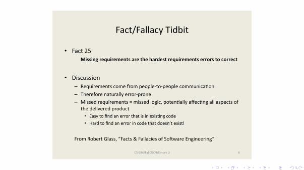
Fact/FallacyTidbit
• Fact25Missingrequirementsarethehardestrequirementserrorstocorrect
• Discussion– Requirementscomefrompeople‐to‐peoplecommunicaHon
– Thereforenaturallyerror‐prone– Missedrequirements=missedlogic,potenHallyaffecHngallaspectsof
thedeliveredproduct• EasytofindanerrorthatisinexisHngcode• Hardtofindanerrorincodethatdoesn’texist!
FromRobertGlass,“Facts&FallaciesofSoEwareEngineering”
CS‐584/Fall2009/EmoryU 6

(c) thedataqualitychronicle.org
These slides are designed to accompany Software Engineering: A Practitioner’s Approach, 7/e
(McGraw-Hill 2009). Slides copyright 2009 by Roger Pressman. 3
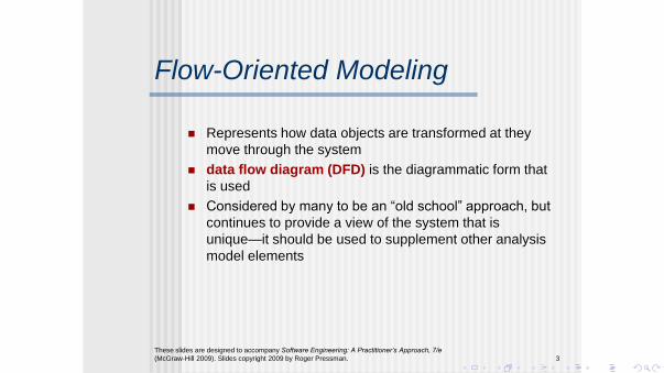
Flow-Oriented Modeling
Represents how data objects are transformed at they
move through the system
data flow diagram (DFD) is the diagrammatic form that
is used
Considered by many to be an “old school” approach, but
continues to provide a view of the system that is
unique—it should be used to supplement other analysis
model elements

Data-flow: good for parallelism
Used in LabView programming language and Matlab’s Simulink:
Data-flow is good for:no variablesclear indication towhere to free memoryindependent datastreams can beprocessed in parallel
Günay (Emory MathCS) Requirements Modeling, Part 2 Fall 2014 4 / 7

Data-flow: good for parallelism
Used in LabView programming language and Matlab’s Simulink:
Data-flow is good for:no variablesclear indication towhere to free memoryindependent datastreams can beprocessed in parallel
Günay (Emory MathCS) Requirements Modeling, Part 2 Fall 2014 4 / 7

These slides are designed to accompany Software Engineering: A Practitioner’s Approach, 7/e
(McGraw-Hill 2009). Slides copyright 2009 by Roger Pressman. 4
The Flow Model
Every computer-based system is an
information transform ....
computer based system
input output

These slides are designed to accompany Software Engineering: A Practitioner’s Approach, 7/e
(McGraw-Hill 2009). Slides copyright 2009 by Roger Pressman. 5
Flow Modeling Notation
external entity
process
data flow
data store

These slides are designed to accompany Software Engineering: A Practitioner’s Approach, 7/e
(McGraw-Hill 2009). Slides copyright 2009 by Roger Pressman. 6
External Entity
A producer or consumer of data
Examples: a person, a device, a sensor
Another example: computer-based
system
Data must always originate somewhere
and must always be sent to something

These slides are designed to accompany Software Engineering: A Practitioner’s Approach, 7/e
(McGraw-Hill 2009). Slides copyright 2009 by Roger Pressman. 7
Process
A data transformer (changes input to output)
Examples: compute taxes, determine area,
format report, display graph
Data must always be processed in some
way to achieve system function

These slides are designed to accompany Software Engineering: A Practitioner’s Approach, 7/e
(McGraw-Hill 2009). Slides copyright 2009 by Roger Pressman. 8
Data Flow
Data flows through a system, beginning
as input and transformed into output.
compute
triangle
area
base
height
area
These slides are designed to accompany Software Engineering: A Practitioner’s Approach, 7/e
(McGraw-Hill 2009). Slides copyright 2009 by Roger Pressman. 9
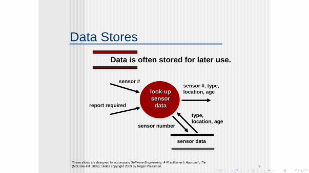
Data Stores
Data is often stored for later use.
look-up
sensor
data
sensor #
report required
sensor #, type,
location, age
sensor data
sensor number
type,
location, age
These slides are designed to accompany Software Engineering: A Practitioner’s Approach, 7/e
(McGraw-Hill 2009). Slides copyright 2009 by Roger Pressman. 10
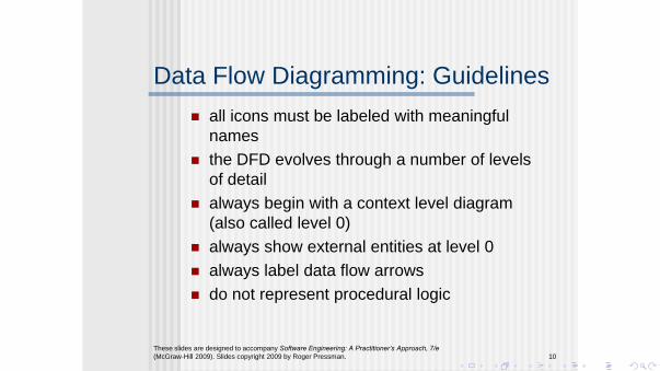
Data Flow Diagramming: Guidelines
all icons must be labeled with meaningful
names
the DFD evolves through a number of levels
of detail
always begin with a context level diagram
(also called level 0)
always show external entities at level 0
always label data flow arrows
do not represent procedural logic

These slides are designed to accompany Software Engineering: A Practitioner’s Approach, 7/e
(McGraw-Hill 2009). Slides copyright 2009 by Roger Pressman. 11
Constructing a DFD—I
review user scenarios and/or the data model to isolate data objects and use a grammatical parse to determine “operations”
determine external entities (producers and consumers of data)
create a level 0 DFD

These slides are designed to accompany Software Engineering: A Practitioner’s Approach, 7/e
(McGraw-Hill 2009). Slides copyright 2009 by Roger Pressman. 12
Level 0 DFD Example
user processing
request
video source NTSC
video signal
digital video
processor
requested video signal
monitor

These slides are designed to accompany Software Engineering: A Practitioner’s Approach, 7/e
(McGraw-Hill 2009). Slides copyright 2009 by Roger Pressman. 13
Constructing a DFD—II
write a narrative describing the transform
parse to determine next level transforms
“balance” the flow to maintain data flow
continuity
develop a level 1 DFD
use a 1:5 (approx.) expansion ratio


These slides are designed to accompany Software Engineering: A Practitioner’s Approach, 7/e
(McGraw-Hill 2009). Slides copyright 2009 by Roger Pressman. 14
The Data Flow Hierarchy
P a b
x y
p1
p2
p3
p4 5
a
b
c
d e
f
g
level 0
level 1

These slides are designed to accompany Software Engineering: A Practitioner’s Approach, 7/e
(McGraw-Hill 2009). Slides copyright 2009 by Roger Pressman. 15
Flow Modeling Notes
each bubble is refined until it does just
one thing
the expansion ratio decreases as the
number of levels increase
most systems require between 3 and 7
levels for an adequate flow model
a single data flow item (arrow) may be
expanded as levels increase (data
dictionary provides information)

These slides are designed to accompany Software Engineering: A Practitioner’s Approach, 7/e
(McGraw-Hill 2009). Slides copyright 2009 by Roger Pressman. 16
Process Specification (PSPEC)
PSPEC
narrative
pseudocode (PDL)
equations
tables
diagrams and/or charts
bubble

These slides are designed to accompany Software Engineering: A Practitioner’s Approach, 7/e
(McGraw-Hill 2009). Slides copyright 2009 by Roger Pressman. 17
Maps into
DFDs: A Look Ahead
analysis model
design model

(c) sodahead.com
These slides are designed to accompany Software Engineering: A Practitioner’s Approach, 7/e
(McGraw-Hill 2009). Slides copyright 2009 by Roger Pressman. 18
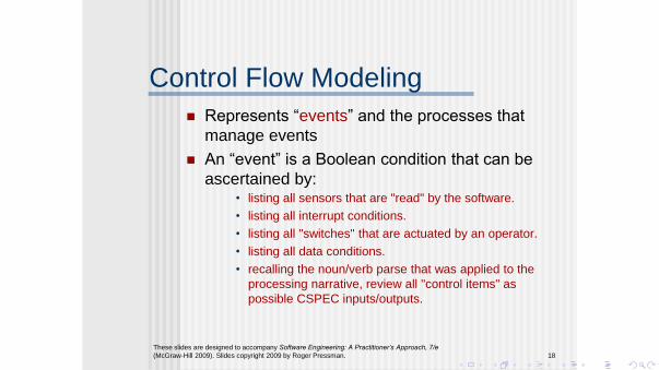
Control Flow Modeling
Represents “events” and the processes that
manage events
An “event” is a Boolean condition that can be
ascertained by: • listing all sensors that are "read" by the software.
• listing all interrupt conditions.
• listing all "switches" that are actuated by an operator.
• listing all data conditions.
• recalling the noun/verb parse that was applied to the
processing narrative, review all "control items" as
possible CSPEC inputs/outputs.

These slides are designed to accompany Software Engineering: A Practitioner’s Approach, 7/e
(McGraw-Hill 2009). Slides copyright 2009 by Roger Pressman. 19
Control Specification (CSPEC)
The CSPEC can be:
state diagram (sequential spec)
state transition table
decision tables
activation tables
combinatorial spec

These slides are designed to accompany Software Engineering: A Practitioner’s Approach, 7/e
(McGraw-Hill 2009). Slides copyright 2009 by Roger Pressman. 20
Behavioral Modeling
The behavioral model indicates how software will
respond to external events or stimuli. To create the
model, the analyst must perform the following steps:
• Evaluate all use-cases to fully understand the sequence of
interaction within the system.
• Identify events that drive the interaction sequence and
understand how these events relate to specific objects.
• Create a sequence for each use-case.
• Build a state diagram for the system.
• Review the behavioral model to verify accuracy and
consistency.
These slides are designed to accompany Software Engineering: A Practitioner’s Approach, 7/e
(McGraw-Hill 2009). Slides copyright 2009 by Roger Pressman. 21
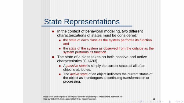
State Representations In the context of behavioral modeling, two different
characterizations of states must be considered:
the state of each class as the system performs its function and
the state of the system as observed from the outside as the system performs its function
The state of a class takes on both passive and active characteristics [CHA93].
A passive state is simply the current status of all of an object’s attributes.
The active state of an object indicates the current status of the object as it undergoes a continuing transformation or processing.

These slides are designed to
accompany Software
Engineering: A Practitioner’s
Approach, 7/e (McGraw-Hill
2009). Slides copyright 2009
by Roger Pressman.
22
State Diagram for the
ControlPanel Class
reading
locked
select ing
password
ent ered
comparing
password = incorrect
& numberOfTries < maxTries
password = correct
act ivat ion successful
key hit
do: validat ePassword
numberOfTries > maxTries
t imer < lockedTime
t imer > lockedTime
These slides are designed to accompany Software Engineering: A Practitioner’s Approach, 7/e
(McGraw-Hill 2009). Slides copyright 2009 by Roger Pressman. 23
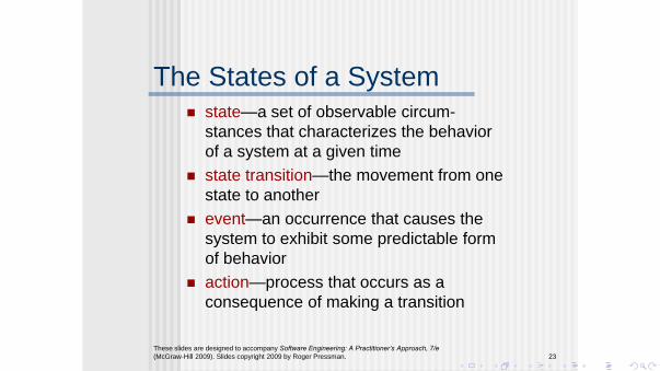
The States of a System state—a set of observable circum-
stances that characterizes the behavior
of a system at a given time
state transition—the movement from one
state to another
event—an occurrence that causes the
system to exhibit some predictable form
of behavior
action—process that occurs as a
consequence of making a transition

These slides are designed to accompany Software Engineering: A Practitioner’s Approach, 7/e
(McGraw-Hill 2009). Slides copyright 2009 by Roger Pressman. 24
Behavioral Modeling
make a list of the different states of a system
(How does the system behave?)
indicate how the system makes a transition
from one state to another (How does the
system change state?)
indicate event
indicate action
draw a state diagram or a sequence diagram

homeowner cont ro l panel sensorssyst em sensors
syst em
ready
reading
request lookupcomparing
result
password ent ered
password = correct
request act ivat ion
act ivat ion successfu l
lockednum berOfTries > m axTries
select ing
t imer > lockedTimeA
A
Figure 8 .2 7 Sequence diagram (part ial) f or Saf eHome securit y f unct ion
act ivat ion successfu l
These slides are
designed to
accompany
Software
Engineering: A
Practitioner’s
Approach, 7/e
(McGraw-Hill
2009). Slides
copyright 2009 by
Roger Pressman.
25
Sequence Diagram

Control-flow Modeling
Model View Controller (MVC) framework for WebApps
Günay (Emory MathCS) Requirements Modeling, Part 2 Fall 2014 7 / 7
These slides are designed to accompany Software Engineering: A Practitioner’s Approach, 7/e
(McGraw-Hill 2009). Slides copyright 2009 by Roger Pressman. 35
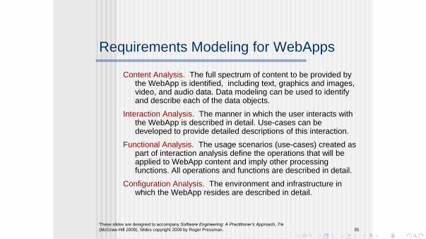
Requirements Modeling for WebApps
Content Analysis. The full spectrum of content to be provided by the WebApp is identified, including text, graphics and images, video, and audio data. Data modeling can be used to identify and describe each of the data objects.
Interaction Analysis. The manner in which the user interacts with the WebApp is described in detail. Use-cases can be developed to provide detailed descriptions of this interaction.
Functional Analysis. The usage scenarios (use-cases) created as part of interaction analysis define the operations that will be applied to WebApp content and imply other processing functions. All operations and functions are described in detail.
Configuration Analysis. The environment and infrastructure in which the WebApp resides are described in detail.

These slides are designed to accompany Software Engineering: A Practitioner’s Approach, 7/e
(McGraw-Hill 2009). Slides copyright 2009 by Roger Pressman. 37
The Content Model
Content objects are extracted from use-cases
examine the scenario description for direct and
indirect references to content
Attributes of each content object are identified
The relationships among content objects
and/or the hierarchy of content maintained by a
WebApp
Relationships—entity-relationship diagram or UML
Hierarchy—data tree or UML

Figure 1 8 .3 Dat a t ree for a SafeHom e com ponent
component
part Number
part Name
part Type
descript ion
price
Market ingDescript ion
Phot ograph
TechDescript ion
Schemat ic
Video
WholesalePrice
Ret ailPr iceThese slides are designed to accompany Software Engineering: A Practitioner’s Approach, 7/e
(McGraw-Hill 2009). Slides copyright 2009 by Roger Pressman. 38
Data Tree

These slides are designed to accompany Software Engineering: A Practitioner’s Approach, 7/e
(McGraw-Hill 2009). Slides copyright 2009 by Roger Pressman. 39
The Interaction Model
Composed of four elements:
use-cases
sequence diagrams
state diagrams
a user interface prototype
Each of these is an important UML notation
and is described in Appendix I

Figure 18.5 Sequence diagram for use-case: select SafeHome components
new cust omer
:Room :FloorPlan
desc ribes
room *plac es room
in f loor p lan
:Product
Component
selec t s produc t c om ponent *
:Billof
Mat erials
add t o BoM
FloorPlan
Reposit ory
sav e f loor p lan c onf igurat ion
sav e b i l l o f m at eria ls
BoM
Reposit ory
These slides are designed to
accompany Software Engineering: A
Practitioner’s Approach, 7/e
(McGraw-Hill 2009). Slides copyright
2009 by Roger Pressman.
40
Sequence Diagram

These slides are
designed to
accompany Software
Engineering: A
Practitioner’s
Approach, 7/e
(McGraw-Hill 2009).
Slides copyright 2009
by Roger Pressman.
41
State Diagram
Figure 1 8 .6 Part ial st at e diagram f or ne w c us t ome r int eract ion
n e w cu st o m e r
Validat ing user
system status=“input ready”
display msg = “enter userid”
display msg =“enter pswd”
ent ry/ log-in requested
do: run user validat ion
exit / set user access swit ch
select “log-in”
userid
validated
password validated
Select ing user act ion
system status=“ link ready”
display: navigat ion choices”
ent ry/ validated user
do: link as required
exit /user act ion selected
select other funct ions
select customizat ion funct ionalit y
select e-commerce (purchase) funct ionalit y
Customizing
system status=“ input ready”
display: basic inst ruct ions
ent ry/validated user
do: process user select ion
exit / customizat ion terminated
select descript ive
content
room being def ined
Def ining room
system status=“input ready”
display: room def . window
ent ry/ room def . selected
do: run room queries
do: store room variables
exit / room completed
select descript ive
content
Building f loor plan
system status=“input ready ”
display: f loor plan window
ent ry/ f loor plan selected
do: insert room in place
do: store f loor plan variables
exit / room insert ion completed
select descript ive
content
select enter room in f loor plan
Saving f loor plan
system status=“input ready ”
display: storage indicator
ent ry/ f loor plan save selected
do: store f loor plan
exit / save completed
select save f loor plan
room insert ion completed
next select ion
customizat ion complete
all rooms
def ined
These slides are designed to accompany Software Engineering: A Practitioner’s Approach, 7/e
(McGraw-Hill 2009). Slides copyright 2009 by Roger Pressman. 42
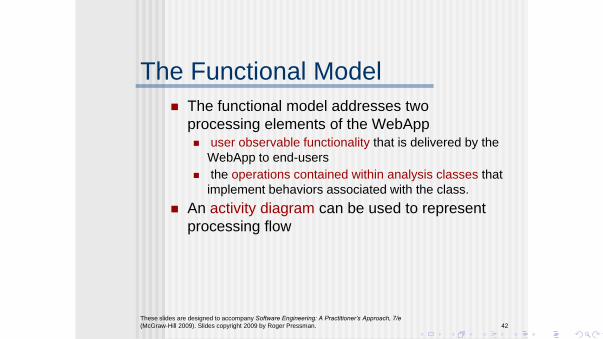
The Functional Model
The functional model addresses two
processing elements of the WebApp user observable functionality that is delivered by the
WebApp to end-users
the operations contained within analysis classes that
implement behaviors associated with the class.
An activity diagram can be used to represent
processing flow

These slides are
designed to accompany
Software Engineering:
A Practitioner’s
Approach, 7/e
(McGraw-Hill 2009).
Slides copyright 2009
by Roger Pressman.
43
Activity Diagram
Figure 1 8 .7 Act ivit y diagram f or c omput e Pr i c e( ) ope r a t i on
init ialize t ot alCost
invoke
calcShippingCostget price and quant it y
components remain on BoMList
invoke det ermineDiscount
discount < = 0
discount>0t ot alCost= t ot alCost - discount
t axTot al=
t ot alCost x t axrat e
no components remain on BoMList
lineCost =
price x quant it y
add lineCost t o
t ot alCost
priceTot al =
t ot alCost + t axTot al + shippingCost
ret urns: shippingCost
ret urns: discount
These slides are designed to accompany Software Engineering: A Practitioner’s Approach, 7/e
(McGraw-Hill 2009). Slides copyright 2009 by Roger Pressman. 44
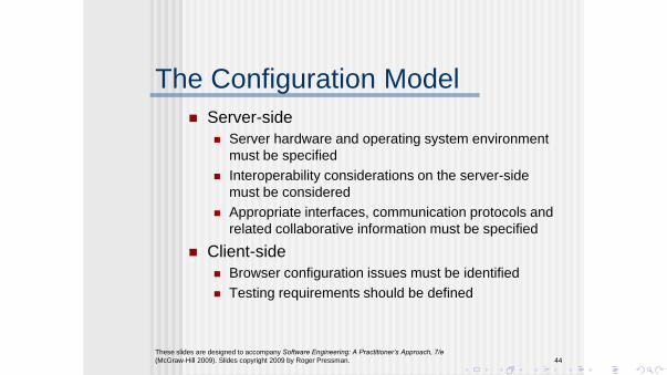
The Configuration Model
Server-side
Server hardware and operating system environment
must be specified
Interoperability considerations on the server-side
must be considered
Appropriate interfaces, communication protocols and
related collaborative information must be specified
Client-side
Browser configuration issues must be identified
Testing requirements should be defined

These slides are designed to accompany Software Engineering: A Practitioner’s Approach, 7/e
(McGraw-Hill 2009). Slides copyright 2009 by Roger Pressman. 45
Navigation Modeling-I Should certain elements be easier to reach (require
fewer navigation steps) than others? What is the priority for presentation?
Should certain elements be emphasized to force users to navigate in their direction?
How should navigation errors be handled?
Should navigation to related groups of elements be given priority over navigation to a specific element.
Should navigation be accomplished via links, via search-based access, or by some other means?
Should certain elements be presented to users based on the context of previous navigation actions?
Should a navigation log be maintained for users?
These slides are designed to accompany Software Engineering: A Practitioner’s Approach, 7/e
(McGraw-Hill 2009). Slides copyright 2009 by Roger Pressman. 46
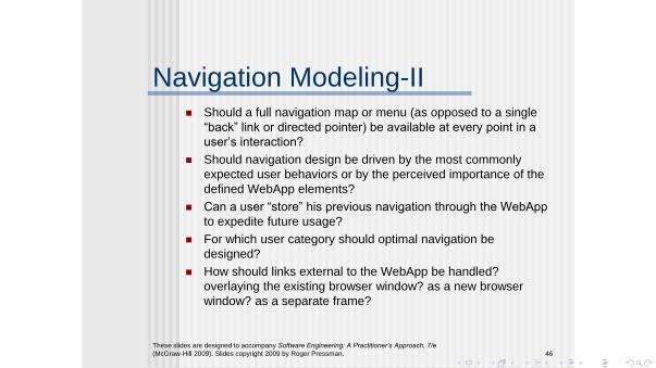
Navigation Modeling-II Should a full navigation map or menu (as opposed to a single
“back” link or directed pointer) be available at every point in a
user’s interaction?
Should navigation design be driven by the most commonly
expected user behaviors or by the perceived importance of the
defined WebApp elements?
Can a user “store” his previous navigation through the WebApp
to expedite future usage?
For which user category should optimal navigation be
designed?
How should links external to the WebApp be handled?
overlaying the existing browser window? as a new browser
window? as a separate frame?

Fact/FallacyTidbit
• Fact26Thelistof“derivedrequirements”canbe50xlongerthanthelistoforiginalrequirements
• Discussion– Requirementsinformthedesign;thedesigninformsthesoluGon;thesoluGoncreates
newrequirements– Complexitymayincreaseaswell– Requirementstraceabilityisaffected
• Traceabilityinvolvesmappingacustomerrequirementtoeachpartofthedesign/code/test/documentaGon
• SomeGmesusedforcodeanalysis–idenGfyingdanglingcode,forexample(i.e.,codethatnolongermeetsarequirement)
• Design“consequences”(implicitrequirements)aren’tGeddirectlytoanoriginalcustomerrequirement,somappingisunclearatbest
• EachphaseoftheprojectandaddiGonoffurtherimplicitrequirementsaddstothetraceabilityproblem;nojustasimplelinked‐listproblembutlinked‐listsoflinked‐lists–extremelycomplex
FromRobertGlass,“Facts&FallaciesofSofwareEngineering”
CS‐584/Fall2009/EmoryU 28


